WO2024257889A1 - 画像形成装置 - Google Patents
画像形成装置 Download PDFInfo
- Publication number
- WO2024257889A1 WO2024257889A1 PCT/JP2024/027680 JP2024027680W WO2024257889A1 WO 2024257889 A1 WO2024257889 A1 WO 2024257889A1 JP 2024027680 W JP2024027680 W JP 2024027680W WO 2024257889 A1 WO2024257889 A1 WO 2024257889A1
- Authority
- WO
- WIPO (PCT)
- Prior art keywords
- support plate
- droplets
- image forming
- paper
- endless belt
- Prior art date
- Legal status (The legal status is an assumption and is not a legal conclusion. Google has not performed a legal analysis and makes no representation as to the accuracy of the status listed.)
- Ceased
Links
Images



Classifications
-
- B—PERFORMING OPERATIONS; TRANSPORTING
- B41—PRINTING; LINING MACHINES; TYPEWRITERS; STAMPS
- B41J—TYPEWRITERS; SELECTIVE PRINTING MECHANISMS, i.e. MECHANISMS PRINTING OTHERWISE THAN FROM A FORME; CORRECTION OF TYPOGRAPHICAL ERRORS
- B41J11/00—Devices or arrangements of selective printing mechanisms, e.g. ink-jet printers or thermal printers, for supporting or handling copy material in sheet or web form
- B41J11/02—Platens
-
- B—PERFORMING OPERATIONS; TRANSPORTING
- B41—PRINTING; LINING MACHINES; TYPEWRITERS; STAMPS
- B41J—TYPEWRITERS; SELECTIVE PRINTING MECHANISMS, i.e. MECHANISMS PRINTING OTHERWISE THAN FROM A FORME; CORRECTION OF TYPOGRAPHICAL ERRORS
- B41J2/00—Typewriters or selective printing mechanisms characterised by the printing or marking process for which they are designed
- B41J2/005—Typewriters or selective printing mechanisms characterised by the printing or marking process for which they are designed characterised by bringing liquid or particles selectively into contact with a printing material
- B41J2/01—Ink jet
-
- B—PERFORMING OPERATIONS; TRANSPORTING
- B41—PRINTING; LINING MACHINES; TYPEWRITERS; STAMPS
- B41J—TYPEWRITERS; SELECTIVE PRINTING MECHANISMS, i.e. MECHANISMS PRINTING OTHERWISE THAN FROM A FORME; CORRECTION OF TYPOGRAPHICAL ERRORS
- B41J2/00—Typewriters or selective printing mechanisms characterised by the printing or marking process for which they are designed
- B41J2/005—Typewriters or selective printing mechanisms characterised by the printing or marking process for which they are designed characterised by bringing liquid or particles selectively into contact with a printing material
- B41J2/01—Ink jet
- B41J2/135—Nozzles
- B41J2/165—Prevention or detection of nozzle clogging, e.g. cleaning, capping or moistening for nozzles
-
- B—PERFORMING OPERATIONS; TRANSPORTING
- B41—PRINTING; LINING MACHINES; TYPEWRITERS; STAMPS
- B41J—TYPEWRITERS; SELECTIVE PRINTING MECHANISMS, i.e. MECHANISMS PRINTING OTHERWISE THAN FROM A FORME; CORRECTION OF TYPOGRAPHICAL ERRORS
- B41J2/00—Typewriters or selective printing mechanisms characterised by the printing or marking process for which they are designed
- B41J2/005—Typewriters or selective printing mechanisms characterised by the printing or marking process for which they are designed characterised by bringing liquid or particles selectively into contact with a printing material
- B41J2/01—Ink jet
- B41J2/17—Ink jet characterised by ink handling
-
- B—PERFORMING OPERATIONS; TRANSPORTING
- B65—CONVEYING; PACKING; STORING; HANDLING THIN OR FILAMENTARY MATERIAL
- B65H—HANDLING THIN OR FILAMENTARY MATERIAL, e.g. SHEETS, WEBS, CABLES
- B65H5/00—Feeding articles separated from piles; Feeding articles to machines
- B65H5/02—Feeding articles separated from piles; Feeding articles to machines by belts or chains, e.g. between belts or chains
Definitions
- the present invention relates to an image forming device.
- Patent Document 1 discloses an image recording device equipped with a conveyor belt that conveys paper.
- the conveyor belt has numerous through holes that suck in air to adhere the paper to the surface of the conveyor belt, and multiple through holes for flushing through which ink ejected from the nozzles passes during flushing.
- the ink ejected from the nozzles during flushing passes through the through holes in the conveyor belt and accumulates in the droplet receiving section. At this time, the ink may adhere to areas other than the conveyor belt or the bottom of the droplet receiving section.
- the present invention was made in consideration of the above problems, and its purpose is to provide an image forming device in which ink is less likely to adhere to any part other than the bottom of the droplet receiving section.
- An image forming apparatus includes a recording head that ejects droplets onto a recording medium, an endless belt that transports the recording medium toward an image forming position by the recording head, a support plate that supports the endless belt, and a suction device that is located on the opposite side of the endless belt from the recording head and sucks the recording medium onto the surface of the endless belt together with air, the endless belt having communication holes through which the droplets pass, the suction device having a droplet receiving section that receives the droplets that have passed through the communication holes, the droplet receiving section including a receiving tray section that receives the droplets and a connection section that connects the receiving tray section and the support plate, the connection section including an opening.
- the present invention makes it difficult for ink to adhere to any part other than the bottom of the droplet receiving section.
- FIG. 1 is a schematic diagram illustrating a configuration of an image forming apparatus according to an embodiment of the present invention.
- FIG. 2 is a plan view showing a conveying unit of the image forming apparatus according to the embodiment.
- FIG. 2 is a perspective view showing a conveying unit of the image forming apparatus according to the embodiment;
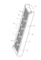
- FIG. 2 is a perspective view showing a support plate of the image forming apparatus according to the embodiment.
- 1 is a schematic enlarged view of a portion of an image forming apparatus according to an embodiment of the present invention;
- FIG. 1 is a schematic diagram showing the configuration of the image forming apparatus 1 according to this embodiment.
- the image forming device 1 is a device that forms images, such as a color multifunction printer, and has the functionality to execute multiple jobs such as copying, printing, scanning, and faxing.
- the image forming device 1 has a printing unit 3 that records images, etc., on paper 2 (an example of a recording medium) using, for example, an inkjet method, a paper feed unit 4 that supplies paper 2 to the printing unit 3, and a drying unit 5 that dries the paper 2 on which the image, etc. has been recorded.
- the paper 2 supplied from the paper feed unit 4 to the printing unit 3 has images and other information recorded on it, and is then transferred from the printing unit 3 to the drying unit 5, where it is dried and discharged.
- the printing unit 3 of the image forming device 1 is equipped with a transport unit 7 that transports the paper 2, and a recording unit 8 that ejects ink onto the paper 2 being transported.
- the recording unit 8 is equipped with multiple head units 11 to 14. Each of the head units 11 to 14 has multiple recording heads 16.
- the conveying section 7 has a frame body 20, a number of rollers 21-24 rotatably mounted on the frame body 20, an endless conveying belt 26 (an example of an endless belt) wound around the rollers 21-24, a support plate 27 (also called a platen) that supports the conveying belt 26 from below, and a suction device 28 that sucks the paper 2 supplied onto the conveying belt 26 onto the surface of the conveying belt 26.
- an endless conveying belt 26 an example of an endless belt wound around the rollers 21-24
- a support plate 27 also called a platen
- a suction device 28 that sucks the paper 2 supplied onto the conveying belt 26 onto the surface of the conveying belt 26.
- Figure 2 is a plan view showing the conveying section 7 of the image forming apparatus 1 according to this embodiment.
- Figure 3 is a perspective view showing the conveying section 7 of the image forming apparatus 1 according to this embodiment.
- the frame body 20 has a pair of side frames 32 that face each other in the belt width direction 38.
- the rollers 21 to 24 are supported between the pair of side frames 32.
- One of the rollers 21 to 24 is forcibly rotated by a motor or the like, which causes the conveyor belt 26 to rotate in one direction and the remaining rollers to rotate accordingly.
- the conveyor belt 26 conveys the paper 2 toward the image formation position by the recording head 16.
- the conveyor belt 26 is colored black to absorb light.
- the suction device 28 has a suction chamber 30 formed below the support plate 27 and a number of suction fans 31 provided within the suction chamber 30.
- the support plate 27 forms the ceiling of the suction chamber 30. In other words, the suction device 28 is located on the opposite side of the conveyor belt 26 from the recording head 16.
- the conveyor belt 26 is formed with a large number of suction holes 34 penetrating both sides and a plurality of through holes 35 for flushing.
- the diameter of the through holes 35 is set to be larger than the diameter of the suction holes 34.
- the through holes 35 are formed in a plurality of sets in two rows in the moving direction 37 of the conveyor belt 26.
- the support plate 27 is formed with a number of intake holes 41 that penetrate in the vertical direction, and a number of communication holes 42 for flushing.
- the opening area of each communication hole 42 is set to be larger than the opening area of each intake hole 41.
- the communication holes 42 are located directly below each recording head 16.
- FIG. 5 is a schematic diagram showing an enlarged portion of the image forming apparatus 1 according to this embodiment.
- a number of droplet receivers 44 are provided in the suction chamber 30 to receive ink droplets 43 that do not contribute to image formation and that are ejected from the recording head 16 by flushing and pass through the through holes 35 of the conveyor belt 26 and the communication holes 42 of the support plate 27.
- the droplet receivers 44 are provided at positions below each communication hole 42.
- the droplet receivers 44 are formed in a box shape with an open upper portion facing the support plate 27.
- the paper 2 is transported in the moving direction 37 without lifting off the transport belt 26.
- ink droplets are ejected from the recording head 16 onto the paper 2 being transported, forming an image on the paper 2.
- the droplet receiving section 44 which receives the droplets 43 ejected from the recording head 16 by flushing, includes a receiving tray section 45 and a connection section 46.
- the receiving tray section 45 forms the bottom of the droplet receiving section 44 and receives the droplets 43.
- the droplets 43 ejected from the recording head 16 by flushing pass through the through-holes 35 and the communication holes 42, fall down the droplet receiving section 44, and reach and adhere to the receiving tray section 45.
- the receiving tray section 45 is located below the recording head 16 in the vertical direction.
- the shape of the receiving tray section 45 is not particularly limited.
- connection portion 46 connects the receiving tray portion 45 and the support plate 27.
- the connection portion 46 forms a side wall portion with respect to the bottom portion of the droplet receiving portion 44.
- the upper end of the side wall portion constituting the connection portion 46 contacts the bottom portion of the support plate 27.
- the contact position of the upper end of the side wall portion with the bottom portion of the support plate 27 is outside the outer edge of the communication hole 42 formed in the support plate 27.
- the upper end of the side wall portion is attached to the bottom portion of the support plate 27 at the above-mentioned contact position.
- the droplet receiving portion 44 is installed in a state where the open upper portion of the droplet receiving portion 44 covers the communication hole 42 of the support plate 27 from below.
- the connection portion 46 includes one or more openings 47.
- the openings 47 function as vents in the connection portion 46.
- the shape, orientation, number, and position of the openings 47 in the connection portion 46 are not particularly limited.
- the openings 47 are formed in the side wall portions of the connection portion 46 that are aligned and opposed to each other in the moving direction 37 of the conveyor belt 26.
- air flows D1 to D3 are likely to occur between the inside and outside of the connection portion 46. Therefore, the air flow is rectified inside and outside the connection portion 46, making it easier for the droplets 43 ejected from the recording head 16 by flushing to reach the receiving tray portion 45. Therefore, the ink droplets 43 are less likely to adhere to any part other than the bottom of the droplet receiving portion 44, such as the connection portion 46.
- each component shown in the drawings mainly show each component in a schematic manner in order to facilitate understanding of the invention, and the thickness, length, number, spacing, etc. of each component shown in the drawings may differ from the actual ones due to the convenience of creating the drawings.
- the configuration of each component shown in the above embodiment is one example and is not particularly limited, and it goes without saying that various modifications are possible within a range that does not substantially deviate from the effects of the present invention.
- the present invention can be used in the field of image forming devices.
Landscapes
- Engineering & Computer Science (AREA)
- Mechanical Engineering (AREA)
- Ink Jet (AREA)
Priority Applications (1)
| Application Number | Priority Date | Filing Date | Title |
|---|---|---|---|
| JP2025528164A JPWO2024257889A1 (https=) | 2023-06-15 | 2024-08-02 |
Applications Claiming Priority (2)
| Application Number | Priority Date | Filing Date | Title |
|---|---|---|---|
| JP2023-098694 | 2023-06-15 | ||
| JP2023098694 | 2023-06-15 |
Publications (1)
| Publication Number | Publication Date |
|---|---|
| WO2024257889A1 true WO2024257889A1 (ja) | 2024-12-19 |
Family
ID=93852224
Family Applications (1)
| Application Number | Title | Priority Date | Filing Date |
|---|---|---|---|
| PCT/JP2024/027680 Ceased WO2024257889A1 (ja) | 2023-06-15 | 2024-08-02 | 画像形成装置 |
Country Status (2)
| Country | Link |
|---|---|
| JP (1) | JPWO2024257889A1 (https=) |
| WO (1) | WO2024257889A1 (https=) |
Citations (7)
| Publication number | Priority date | Publication date | Assignee | Title |
|---|---|---|---|---|
| JP2006159556A (ja) * | 2004-12-06 | 2006-06-22 | Seiko Epson Corp | 液体噴射装置および液体噴射装置における液体予備吐出方法 |
| JP2009137227A (ja) * | 2007-12-10 | 2009-06-25 | Ricoh Co Ltd | 液滴回収装置と液滴吐出装置及び画像形成装置 |
| JP2010241109A (ja) * | 2009-03-16 | 2010-10-28 | Ricoh Co Ltd | インクジェット記録装置と画像形成装置 |
| JP2011207214A (ja) * | 2010-03-10 | 2011-10-20 | Ricoh Co Ltd | 画像形成装置及びプログラム |
| JP2014117844A (ja) * | 2012-12-14 | 2014-06-30 | Ricoh Co Ltd | 空吐出受けと画像形成装置 |
| US20200290373A1 (en) * | 2019-03-14 | 2020-09-17 | Xerox Corporation | Vacuum transport having jetting area allowing periodic jetting of all nozzles |
| WO2022004348A1 (ja) * | 2020-06-29 | 2022-01-06 | 京セラドキュメントソリューションズ株式会社 | インクジェット記録装置 |
-
2024
- 2024-08-02 JP JP2025528164A patent/JPWO2024257889A1/ja active Pending
- 2024-08-02 WO PCT/JP2024/027680 patent/WO2024257889A1/ja not_active Ceased
Patent Citations (7)
| Publication number | Priority date | Publication date | Assignee | Title |
|---|---|---|---|---|
| JP2006159556A (ja) * | 2004-12-06 | 2006-06-22 | Seiko Epson Corp | 液体噴射装置および液体噴射装置における液体予備吐出方法 |
| JP2009137227A (ja) * | 2007-12-10 | 2009-06-25 | Ricoh Co Ltd | 液滴回収装置と液滴吐出装置及び画像形成装置 |
| JP2010241109A (ja) * | 2009-03-16 | 2010-10-28 | Ricoh Co Ltd | インクジェット記録装置と画像形成装置 |
| JP2011207214A (ja) * | 2010-03-10 | 2011-10-20 | Ricoh Co Ltd | 画像形成装置及びプログラム |
| JP2014117844A (ja) * | 2012-12-14 | 2014-06-30 | Ricoh Co Ltd | 空吐出受けと画像形成装置 |
| US20200290373A1 (en) * | 2019-03-14 | 2020-09-17 | Xerox Corporation | Vacuum transport having jetting area allowing periodic jetting of all nozzles |
| WO2022004348A1 (ja) * | 2020-06-29 | 2022-01-06 | 京セラドキュメントソリューションズ株式会社 | インクジェット記録装置 |
Also Published As
| Publication number | Publication date |
|---|---|
| JPWO2024257889A1 (https=) | 2024-12-19 |
Similar Documents
| Publication | Publication Date | Title |
|---|---|---|
| JP4596028B2 (ja) | インクジェット記録装置 | |
| JP3978713B2 (ja) | 記録媒体搬送装置、および前記搬送装置を用いた記録装置 | |
| US8646902B2 (en) | Inkjet recording apparatus | |
| JP2010023374A (ja) | 画像記録装置 | |
| JP5932737B2 (ja) | インクジェット記録装置 | |
| WO2024257889A1 (ja) | 画像形成装置 | |
| JP4462832B2 (ja) | 記録媒体搬送装置及び記録装置 | |
| JP2023149703A (ja) | インクジェット記録装置 | |
| JP3978715B2 (ja) | 記録媒体搬送装置及び記録装置 | |
| JP2003285959A (ja) | 記録媒体搬送装置及び記録装置 | |
| JP5593281B2 (ja) | インクジェット記録装置 | |
| JP6311583B2 (ja) | インクジェット記録装置 | |
| JP2025015202A (ja) | 画像形成装置 | |
| JP3135376U (ja) | インクジェット記録装置 | |
| JP3783602B2 (ja) | 記録媒体搬送装置及び記録媒体搬送装置を備えた記録装置 | |
| JP5211908B2 (ja) | 画像記録装置 | |
| JP2024151421A (ja) | 画像形成装置 | |
| JP7760891B2 (ja) | インクジェット記録装置 | |
| JP2009234207A (ja) | 画像形成装置 | |
| JP2023069302A (ja) | インクジェット記録装置 | |
| CN1899821A (zh) | 包括干燥装置的喷墨成像设备 | |
| JP4123984B2 (ja) | 記録媒体搬送装置及び記録装置 | |
| JP2010167573A (ja) | 記録装置 | |
| JP2004358944A (ja) | 記録媒体搬送装置及び記録装置 | |
| JP2024126388A (ja) | 画像形成装置 |
Legal Events
| Date | Code | Title | Description |
|---|---|---|---|
| 121 | Ep: the epo has been informed by wipo that ep was designated in this application |
Ref document number: 24823502 Country of ref document: EP Kind code of ref document: A1 |
|
| ENP | Entry into the national phase |
Ref document number: 2025528164 Country of ref document: JP Kind code of ref document: A |
|
| WWE | Wipo information: entry into national phase |
Ref document number: 2025528164 Country of ref document: JP |
|
| NENP | Non-entry into the national phase |
Ref country code: DE |