WO2024257856A1 - 構造部品 - Google Patents
構造部品 Download PDFInfo
- Publication number
- WO2024257856A1 WO2024257856A1 PCT/JP2024/021683 JP2024021683W WO2024257856A1 WO 2024257856 A1 WO2024257856 A1 WO 2024257856A1 JP 2024021683 W JP2024021683 W JP 2024021683W WO 2024257856 A1 WO2024257856 A1 WO 2024257856A1
- Authority
- WO
- WIPO (PCT)
- Prior art keywords
- area
- bend
- hardness
- surface roughness
- structural component
- Prior art date
- Legal status (The legal status is an assumption and is not a legal conclusion. Google has not performed a legal analysis and makes no representation as to the accuracy of the status listed.)
- Ceased
Links
Images




Classifications
-
- B—PERFORMING OPERATIONS; TRANSPORTING
- B21—MECHANICAL METAL-WORKING WITHOUT ESSENTIALLY REMOVING MATERIAL; PUNCHING METAL
- B21D—WORKING OR PROCESSING OF SHEET METAL OR METAL TUBES, RODS OR PROFILES WITHOUT ESSENTIALLY REMOVING MATERIAL; PUNCHING METAL
- B21D53/00—Making other particular articles
- B21D53/88—Making other particular articles other parts for vehicles, e.g. cowlings, mudguards
-
- B—PERFORMING OPERATIONS; TRANSPORTING
- B21—MECHANICAL METAL-WORKING WITHOUT ESSENTIALLY REMOVING MATERIAL; PUNCHING METAL
- B21D—WORKING OR PROCESSING OF SHEET METAL OR METAL TUBES, RODS OR PROFILES WITHOUT ESSENTIALLY REMOVING MATERIAL; PUNCHING METAL
- B21D22/00—Shaping without cutting, by stamping, spinning, or deep-drawing
- B21D22/02—Stamping using rigid devices or tools
-
- B—PERFORMING OPERATIONS; TRANSPORTING
- B60—VEHICLES IN GENERAL
- B60G—VEHICLE SUSPENSION ARRANGEMENTS
- B60G7/00—Pivoted suspension arms; Accessories thereof
- B60G7/001—Suspension arms, e.g. constructional features
-
- B—PERFORMING OPERATIONS; TRANSPORTING
- B60—VEHICLES IN GENERAL
- B60G—VEHICLE SUSPENSION ARRANGEMENTS
- B60G2206/00—Indexing codes related to the manufacturing of suspensions: constructional features, the materials used, procedures or tools
- B60G2206/01—Constructional features of suspension elements, e.g. arms, dampers, springs
- B60G2206/10—Constructional features of arms
- B60G2206/122—Constructional features of arms the arm having L-shape
-
- B—PERFORMING OPERATIONS; TRANSPORTING
- B60—VEHICLES IN GENERAL
- B60G—VEHICLE SUSPENSION ARRANGEMENTS
- B60G2206/00—Indexing codes related to the manufacturing of suspensions: constructional features, the materials used, procedures or tools
- B60G2206/01—Constructional features of suspension elements, e.g. arms, dampers, springs
- B60G2206/70—Materials used in suspensions
- B60G2206/72—Steel
- B60G2206/722—Plates
-
- B—PERFORMING OPERATIONS; TRANSPORTING
- B60—VEHICLES IN GENERAL
- B60G—VEHICLE SUSPENSION ARRANGEMENTS
- B60G2206/00—Indexing codes related to the manufacturing of suspensions: constructional features, the materials used, procedures or tools
- B60G2206/01—Constructional features of suspension elements, e.g. arms, dampers, springs
- B60G2206/80—Manufacturing procedures
- B60G2206/81—Shaping
- B60G2206/8103—Shaping by folding or bending
-
- B—PERFORMING OPERATIONS; TRANSPORTING
- B60—VEHICLES IN GENERAL
- B60G—VEHICLE SUSPENSION ARRANGEMENTS
- B60G2206/00—Indexing codes related to the manufacturing of suspensions: constructional features, the materials used, procedures or tools
- B60G2206/01—Constructional features of suspension elements, e.g. arms, dampers, springs
- B60G2206/80—Manufacturing procedures
- B60G2206/81—Shaping
- B60G2206/8106—Shaping by thermal treatment, e.g. curing hardening, vulcanisation
- B60G2206/81062—Shaping by thermal treatment, e.g. curing hardening, vulcanisation to relieve internal stresses, e.g. during folding or bending
Definitions
- the present invention relates to structural components.
- ultra-high tensile steel in automobile chassis components has great benefits such as reducing the weight of parts.
- the increased strength achieved by using ultra-high tensile steel tends to reduce formability, so identifying the limits of the material and appropriately designing the part shape can maximize the benefits of using ultra-high tensile steel.
- chassis parts such as lower arms
- structures with bent sections such as M-shaped cross sections are adopted so that the necessary rigidity can be ensured even with thin wall thickness by using high-strength materials.
- the present invention aims to provide a structural component that can suppress the decrease in fatigue durability caused by the surface roughness on the inside of the bend and the shape of the inside of the bend.
- a structural component made of steel plates, A flat portion and a bent portion are included.
- a structural component, wherein the bent portion satisfies the following formulas (1), (2), and (3). 28 ⁇ area ⁇ 45...(1) 0.17 ⁇ r/t ⁇ 6.90 (2) 0.22 ⁇ n'...(3) however, ⁇ area is the square root of the projected area of the microdefect on the inside of the bent part [ ⁇ m] r is the minimum value of the radius of curvature on the inside of the bend [mm] t is the thickness of the flat plate portion [mm] n' is the interquartile range of the nanohardness of the platelet/mean nanohardness.
- the present invention has the effect of providing a structural component that can suppress the decrease in fatigue durability caused by the surface roughness on the inside of the bend and the shape of the inside of the bend.
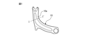
- FIG. 1 is a diagram showing an automobile suspension part as an example of a structural part according to the present disclosure.
- FIG. 2 is a cross-sectional view taken along dashed line I-I' in FIG. 1.
- FIG. 13 is a diagram showing five images of the inside of a bent portion that have been captured and linked together.
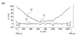
- FIG. 1 is a characteristic diagram showing a method for evaluating surface roughness by converting a curved surface into a flat surface.
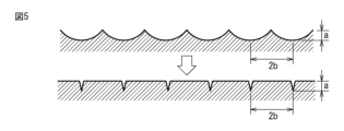
- FIG. 13 is a diagram showing a schematic diagram of the surface roughness on the inside of the bend represented by the characteristic C3.
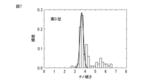
- 1 is a histogram showing the distribution of nano-hardness of a high Si type.
- 1 is a histogram showing the distribution of nano-hardness of a low Si type.
- 1 is a characteristic diagram showing the distribution of uniform elongation u-El (vertical axis) of high Si type and low Si type, and the value n' (horizontal axis) obtained by dividing the interquartile range by the average nano hardness.
- 1 is a characteristic diagram in which ⁇ area and r/t are plotted for each of Examples 1 to 10 of the present invention and Comparative Examples 1 to 10 shown in Table 1.
- a structural part when a structural part includes a bent part that has been bent, the inner side of the bend of the bent part is subjected to compressive deformation, so that the surface properties are reduced compared to before processing, and the surface roughness leads to the deterioration of fatigue properties.
- Chassis parts are important safety parts, and are constantly subjected to vibration and load, so it is essential to increase fatigue durability.
- a structural part that suppresses fatigue cracks from the inner side of the bend is provided by an appropriate combination of material and part structure (especially the surface roughness and bend shape of the inner side of the bend).
- ultra-high tensile steel tensile strength of 980 MPa or more
- a better forming limit than conventional materials
- deterioration of the surface roughness on the inside of the bend in bent parts of press-formed products with M-shaped cross sections is suppressed, resulting in a smooth surface, and enabling forming with a smaller radius of curvature on the inside of the bend.
- the relationship between the range of the radius of curvature on the inside of the bend that satisfies fatigue durability and the material properties is clarified.
- the inventors have found, after extensive research, that by applying an ultra-high tensile steel with a better forming limit than conventional steels, fatigue cracks occurring in the bent portion can be suppressed when the parameters of the bent portion, specifically the surface roughness on the inside of the bend and the radius of curvature on the inside of the bend, satisfy certain conditions.
- the material properties affect the change in surface roughness before and after processing of the bent portion. It is possible to improve fatigue durability by controlling the appropriate surface properties of the bent portion through the material and the shape (design) of the bent portion.
- the steel with a better forming limit according to this embodiment is less likely to have large surface roughness on the inside of the bend after processing (i.e., unevenness is less likely to develop), improving fatigue durability.
- the larger the radius of curvature on the inside of the bend the less likely the surface roughness on the inside of the bend tends to be.
- the ultra-high tensile steels with excellent forming limits according to the present disclosure are a high-Si type with a relatively high Si content, and a low-Si type with a relatively low Si content.
- the two types have different mechanisms for improving fatigue durability.
- the high-Si type has a relatively large surface roughness due to the presence of Si-derived scale, but the n-value (work hardening index) related to formability is high, so microcracks are less likely to develop on the inside of the bend. For this reason, the high-Si type suppresses the folding of the compressed part on the inside of the bend during bending, achieving high durability.
- the low-Si type has a relatively low n-value, but the small surface roughness derived from the Si scale suppresses the development of microcracks on the inside of the bend. For this reason, the low-Si type takes advantage of its excellent surface smoothness to suppress the occurrence of fatigue cracks, achieving high durability.
- the fatigue limit ⁇ W is expressed by the following formula (4) using ⁇ area and Vickers hardness, and therefore they have focused on ⁇ area as a characteristic value that affects fatigue durability.
- the micro defects may mean unevenness on the surface of the press-formed body. In the case of inferior micro defects, they may be observed not only as simple unevenness but also as cracks.
- ⁇ W [1.43(HV+120) ⁇ (1-R)/2 ⁇ ⁇ ]/( ⁇ area) 1/6 ...(4) however, ⁇ W: Fatigue limit [MPa] HV: Vickers hardness [HV kgf/mm 2 ] ⁇ : 0.226+HV ⁇ 10-4 R: Stress ratio ( ⁇ min/ ⁇ max) It is.
- ⁇ area [ ⁇ m] is calculated from the following formulas (5) and (6) based on the description in the above non-patent document 1.
- a [ ⁇ m] is the roughness height (maximum height Rz)
- 2b [ ⁇ m] is the roughness pitch (average element length, wavelength Rsm of the height waveform).
- Structural component according to the present disclosure In the bent portion, the larger the value of ⁇ area, the greater the surface roughness, and therefore the fatigue durability of the structural component decreases. Also, the smaller the value of r/t, the ratio of the curvature radius on the inner side of the bend to the plate thickness of the steel plate, the lower the fatigue durability of the structural member.
- the inventors have thoroughly studied the relationship between ⁇ area and r/t of the structural component and the fatigue properties of the structural component, and have found that when ⁇ area and r/t are within a certain range, the fatigue durability can be improved compared to the conventional case.
- FIG. 1 is a diagram showing an automobile suspension part as an example of a structural part according to the present disclosure, and more specifically, a diagram showing a lower arm 10 of a suspension.
- FIG. 2 is a diagram showing a cross section along the dashed line II' in FIG. 1. Note that the structural part according to the present disclosure is not limited to use in automobiles.
- the lower arm 10 is subjected to pressing, burring, etc., and has a flat plate part (top plate part) 10a and a bent part 10b.
- FIG. 2 shows an M-shaped cross section including the flat plate part 10a and the bent part 10b.
- the present inventors have found that the fatigue properties can be improved compared to conventional methods by satisfying the following formulas (1), (2), and (3), and more preferably by satisfying formulas (1)', (2)', and (3). 28 ⁇ area ⁇ 45...(1) 0.17 ⁇ r/t ⁇ 6.90 (2) 0.22 ⁇ n'...(3) 33 ⁇ area ⁇ 44...(1)' 0.17 ⁇ r/t ⁇ 3.45...(2)' however, ⁇ area: square root of the projected area of a micro defect on the inside of the bent portion 10b (parameter indicating the roughness of the surface after processing) [ ⁇ m] r: minimum value of the radius of curvature on the inner side of the bend of the bent portion 10b [mm] t: thickness of flat plate portion 10a [mm] n': interquartile range/average nanohardness of the flat plate portion 10a.
- the flat portion 10a is a portion in which the thickness reduction from the thickest portion is within 10% and is not significantly distorted by bending.
- the flat portion 10a may be a portion having the same thickness as the material.
- Non-Patent Document 1 As described above, the inventors have thoroughly studied the values of ⁇ area and r/t described in Non-Patent Document 1 when bending sections are formed using ultra-high tensile steel, which has a better forming limit than conventional steels, and have found that by setting the values of ⁇ area and r/t within a certain range, it is possible to improve fatigue properties compared to conventional steels.
- the structural components according to the present disclosure have bent portions formed by press molding, burring, etc.
- bending may be performed with the inner surface of the bent portion in close contact with the die.
- the conditions for bending e.g., inner bend R, die clearance, etc.
- the ⁇ area value of the ground structural components is approximately 6.9, which does not satisfy formula (1), and the structural components according to the present disclosure do not include ground products.
- Figure 4 is a characteristic diagram showing a method for evaluating surface roughness by converting a curved surface into a flat surface using the output coordinates (characteristic C1).
- Gaussian filters are not effective at the ends of characteristic C1, and because characteristics C1 and C2 diverge as shown in Figure 4, data excluding a range of 100 ⁇ m from both ends of characteristic C3 was used to obtain the arithmetic mean roughness Ra and mean element length Rsm.
- Ra is twice the average value of the absolute deviation between characteristic C3 and the average line showing the average of characteristic C3 (average deviation)
- Rsm is the average value of one period of peak-to-valley spacing determined from the intersection where the roughness curve shown by characteristic C3 intersects with the average line.
- the minimum height defining a peak or valley is 2 ⁇ m, and anything below 2 ⁇ m is considered noise and part of the preceding or following peak or valley.
- Figure 5 is a diagram showing the surface roughness on the inside of the bend represented by characteristic C3.
- height a and pitch 2b are values assuming that the surface roughness is periodic unevenness
- ⁇ area in formulas (5) and (6) is a value obtained by assuming that the surface roughness is periodic unevenness.
- the cross section shown in the upper part of Figure 5 can be replaced with the cross section shown in the lower part.
- Ra obtained in the above manner corresponds to the roughness height a in formulas (5) and (6)
- Rsm corresponds to the roughness pitch 2b in formulas (5) and (6). Therefore, Rsm and Ra can be obtained based on the image of the cross section of bent portion 10b, and ⁇ area can be calculated based on formulas (2) and (3).
- the maximum height Rz (the difference between the height of the highest peak and the depth of the lowest valley) may be used as the roughness height a.
- the average pitch of irregularities equal to or greater than as calculated from the following formula (7) may be used as the roughness pitch 2b.
- Both the high Si type and the low Si type are made of ultra-high tensile steel (DP (Dual Phase) steel) with a tensile strength of 980 MPa or more, and have a Vickers hardness HV of 310 or more, preferably 340 or more.
- DP Dual Phase
- HV Vickers hardness
- the Si content is adjusted, and in the high Si type, the n' value described later is adjusted, thereby making it an ultra-high tensile steel with a better forming limit than conventional materials.
- a sample is taken with a cross section perpendicular to the surface of the flat plate portion 10a (i.e., the cross section shown in Figure 2) as the measurement surface, and the measurement surface is prepared for hardness testing.
- the measurement surface is prepared in accordance with JIS Z 2244:2009.
- the measurement surface is polished using silicon carbide paper #600 to #1500, and then the measurement surface is mirror-finished using a diluted solution such as alcohol or a liquid in which diamond powder with a grain size of 1 ⁇ m to 6 ⁇ m is dispersed in pure water.
- a hardness test is performed on the measurement surface thus mirror-finished using the method described in JIS Z 2244:2009. Note that by using the cross section as the measurement surface, the effect of surface coating, etc. on the hardness measurement value can be suppressed.
- a micro Vickers hardness tester is used to measure 30 points at intervals of at least three times the indentation at a position that is 1/4 of the plate thickness of the flat plate portion 10a adjacent to the bent portion 10b of the sample, with a load of 500 gf, and the average value is taken as the hardness of the component.
- High-Si steel sheets have a microstructure composed of ferrite and tempered martensite.
- Ferrite is a soft layer and has advantages in n-value and uniform elongation (u-El). The n-value correlates with uniform elongation, and high-Si steel sheets contain soft ferrite, which gives them a large hardness difference between layers (hardness difference between structures).
- low-Si steel sheets have a microstructure composed mainly of bainite (which may contain tempered martensite and ferrite), and they have a smaller hardness difference between layers (hardness difference between structures) compared to high-Si steel sheets.
- Figure 6 is a histogram showing the distribution of nanohardness for low Si type.
- Figure 7 is a histogram showing the distribution of nanohardness for high Si type.
- the horizontal axis shows nanohardness and the vertical axis shows frequency.
- the sample for measuring nanohardness is taken from the same position as that for measuring the component hardness by the Vickers hardness test described above.
- the measurement surface of the sample is the same as that for the Vickers hardness test.
- the measurement surface is mirror-finished, and nanohardness is measured at a position 1/4 of the plate thickness.
- a load of 2500 uN is applied, and 100 measurements are taken.
- the distance between indentations is ensured to be 5 ⁇ m or more, and the nanohardness (i.e., indentation hardness) is calculated based on ISO 14577-1 (Annex A).
- the interquartile range and average nanohardness are then calculated from the indentation hardness values obtained for the 100 points.
- the high-Si type contains soft ferrite and has a large difference in hardness between structures, so there are two nano-hardness peaks as shown in Figure 7, and it contains a hard layer and a soft layer.
- the high-Si type has excellent n-value characteristics due to the inclusion of a soft layer derived from ferrite.
- the low-Si type has a small difference in hardness between structures, so there is only one nano-hardness peak as shown in Figure 6.
- Figure 8 is a characteristic diagram showing the distribution of uniform elongation (u-El: vertical axis) and the value obtained by dividing the interquartile range by the average nano hardness (n': horizontal axis) for high-Si and low-Si types.
- u-El vertical axis
- n' horizontal axis
- white circles ( ⁇ ) indicate high-Si types
- black circles ( ⁇ ) indicate low-Si types.
- High-Si types have a higher uniform elongation, which indicates work hardening ability, than low-Si types, but as mentioned above, the surface roughness is relatively large due to the presence of Si-derived scale.
- the characteristics of high-Si and low-Si materials are evaluated using the value n' obtained by dividing the interquartile range by the average nanohardness.
- n' can be 0.22 or more, and for low-Si materials, n' can be less than 0.22.
- the high Si type is made of DP steel with a tensile strength of 980 MPa or more, and an n' of 0.22 or more is obtained by setting the Si content to 0.9% or more by mass.
- the high Si type is characterized solely by an n' of 0.22 or more, and apart from this feature and the Si content of 0.9% or more, the chemical composition of the material and the manufacturing method are not fundamentally limited.
- the upper limit of tensile strength can be applied up to approximately 1300 MPa.
- the high Si type has the following chemical composition by mass %: C: 0.01-1.0%, Si: 0.9% or more, Mn: 0.10-5.00%, P: 0.100% or less, S: 0.0300% or less, N: 0.0100% or less, O: 0-0.020%, Al: 0-1.000%, Cr: 0-2.00%, Cu: 0-2.00%, Ni: 0-2.00%, Mo: 0-3.00%, Co: 0-3.00%, Nb: 0-0.150%, V: 0-1.00%, T: 0.01-0.25%, ...01-0.25%, Mn: 0.01-0.25%, Mn: 0.01-0.25%, Mn: 0.01-0.25%, Mn: 0.01-0.25%, Mn: 0.01-0.25%, Mn: 0.01-0.25%, Mn: 0.01-0.25%, Mn: 0.01-0.25%, Mn: 0.01-0.25%, Mn: 0.01-0.25%, Mn: 0.01-0
- It may have a chemical composition consisting of i: 0-1.00%, W: 0-1.00%, Sn: 0-1.00%, Sb: 0-0.50%, Ta: 0-0.10%, As: 0-0.050%, B: 0-0.0100%, Ca: 0-0.100%, Mg: 0-0.100%, Zr: 0-0.100%, Hf: 0-0.100%, Bi: 0-0.100%, Zn: 0-0.200%, REM: 0-0.100%, and the balance: Fe and impurities.
- the lower limit of the content of the optional added element may be 0.0001% or 0.001%.
- steel sheets obtained by rolling steel having the above chemical composition at room temperature to 1300°C, or steel sheets obtained by rolling and then subjecting the steel to surface treatment such as heat treatment or painting may also be used.
- the low-Si type by making the Si content less than 0.9% by mass, the surface roughness caused by the Si-derived scale can be kept small, and n' is less than 0.22.
- the low-Si type is characterized by n' being less than 0.22, and other than this feature and the Si content being less than 0.9%, the chemical components of the material and the manufacturing method are not fundamentally limited.
- the low-Si type may have the same chemical composition as the high-Si type described above, except that the Si content is less than 0.9%.
- the lower limit of the content of optional added elements may be 0.0001% or 0.001%, and a steel sheet obtained by rolling steel having the above chemical composition at room temperature to 1300°C, or a steel sheet obtained by rolling and then performing surface treatment such as heat treatment or painting, may be used.
- the characteristic corresponding to characteristic C3 in Figure 4 can be obtained directly from the image without converting the curved surface to a flat surface.
- a fatigue test was conducted on each of the lower arms of the comparative example and the invention example, in which a load was applied in the longitudinal direction of the vehicle. Specifically, for each of the lower arms of the comparative examples 1 to 8 and the invention examples 1 to 8, which differ in the roughness parameter ⁇ area after processing, a load was applied in the longitudinal direction of the vehicle to the bent portion, and the 200,000 cycles strength ⁇ f was measured. Note that the 200,000 cycles strength is the load stress generated in the lower arm at 200,000 repetitions before fatigue failure occurs.
- the time strength ⁇ f1 of the comparative example was compared with the time strength ⁇ f2 of the invention example to evaluate the fatigue durability of the invention example. Specifically, for each invention example, based on the results compared with the comparative examples, if the value of ⁇ f2/ ⁇ f1 exceeded 1.2, it was evaluated as "Good”, and if the value of ⁇ f2/ ⁇ f1 exceeded 1.4, it was evaluated as "Excellent".
- Figure 9 is a characteristic diagram plotting ⁇ area and r/t for each of the invention examples 1 to 8 and the comparative examples 1 to 8 shown in Table 1.
- open circles ( ⁇ ) indicate invention examples
- filled circles ( ⁇ ) indicate comparative examples.
- the smaller the r/t i.e., the smaller the r, the greater the value of ⁇ area, and the rougher the surface on the inside of the bend becomes, resulting in a decrease in fatigue durability.
- the value of ⁇ area is lower for each of the invention examples 1 to 8 than for each of the comparative examples 1 to 8 with the same r/t, and the surface roughness on the inside of the bend is less likely to deteriorate compared to the comparative examples 1 to 8, and the surface on the inside of the bend is smoother.
- the fatigue properties of the invention examples 1 to 8 are superior to those of the comparative examples 1 to 8.
- the larger the r and the smaller the value of ⁇ area the better the fatigue properties are compared to the comparative examples with the same r.
- the structural member according to the present disclosure satisfies the following formula (9).
- a 5% margin is added to the ⁇ area in formula (8) to set the upper limit.
Landscapes
- Engineering & Computer Science (AREA)
- Mechanical Engineering (AREA)
- Heat Treatment Of Steel (AREA)
- Shaping Metal By Deep-Drawing, Or The Like (AREA)
- Heat Treatment Of Sheet Steel (AREA)
- Bending Of Plates, Rods, And Pipes (AREA)
Abstract
Description
平板部と曲げ部とを有し、
前記曲げ部は、以下の式(1)、式(2)および式(3)を満たす、構造部品。
28≦√area≦45 ・・(1)
0.17≦r/t≦6.90 ・・(2)
0.22≦n’ ・・(3)
但し、
√areaは前記曲げ部の曲げ内側の微小欠陥の投影面積の平方根[μm]
rは前記曲げ部の曲げ内側の曲率半径の最小値 [mm]
tは前記平板部の板厚 [mm]
n’は前記平板部のナノ硬さの四分位範囲/平均ナノ硬さ
である。
33≦√area≦44 ・・(1)’
0.17≦r/t≦3.45 ・・(2)’
33≦√area≦1.05{0.0976( r/t))3-0.7185 (r/t)2-1.0542( r/t)+43.426} ・・(9)
1.本開示の概要
2.曲げ内側の表面に存在する微小欠陥が疲労強度に及ぼす影響
3.本開示に係る構造部品
4.曲げ内側の表面粗さの評価方法
5.高Si型と低Si型について
6.実施例
例えば自動車用の構造部品(構造物を構成する部品)においては、年々高強度化されており、高強度化に伴って薄肉化による軽量化が進んでいる。軽量且つ高機能な構造部品の実現のためには、「高強度薄肉化による部品の軽量化」と「鉄の強度特性を活かすための構造設計」の組み合わせが重要となる。例えば自動車用の構造部品である高強度薄肉化したシャシ部品(例えば、ロアアームなどの足回り部品)においては、薄肉化に伴う剛性低下と加工に伴う表面性状(表面粗さ)の低下に起因して疲労亀裂が発生し、部品の疲労特性が劣化する場合がある。特に、構造部品が曲げ加工された曲げ部を含む場合、曲げ部の曲げ内側は圧縮変形を受けるため、加工前に比べて表面性状が低下し、表面粗さが疲労特性の劣化に繋がる。シャシ部品は重要な保安部品であり、常に振動や負荷を受けており、疲労耐久性を高めることが必要不可欠である。本実施形態では、材料と部品構造(特に、曲げ内側の表面粗さと曲げ形状)の適切な組み合わせにより、曲げ内側からの疲労亀裂発生を抑制する構造部品を提供する。
本発明者らは、曲げ部の曲げ内側の微小欠陥の投影面積の平方根√areaが疲労強度に及ぼす影響を鋭意検討し、上記非特許文献1に記載されているように、疲労限σWが√areaとビッカース硬さによって以下の式(4)で表されることから、疲労耐久性に影響を与える特性値として√areaに着目した。なお、微小欠陥とはプレス成形体表面の凹凸のことを意味するものであってよい。微小欠陥は、劣位なものでは、単なる凹凸にとどまらず、亀裂として観察される場合がある。
σW=[1.43(HV+120){(1-R)/2}α]/(√area)1/6
・・(4)
但し、
σW:疲労限[MPa]
HV:ビッカース硬さ[HV kgf/mm2]
α:0.226+HV×10-4
R:応力比(σmin/σmax)
である。
(但し、a/2b≦0.195の場合)
(但し、a/2b>0.195の場合)
曲げ部においては、√areaの値が大きいほど表面粗さが大きくなるため、構造部品の疲労耐久性は低下する。また、鋼板の板厚に対する曲げ内側の曲率半径の比r/tの値が小さいほど構造部材の疲労耐久性は低下する。本発明者らは、構造部品の√areaおよびr/tと、構造部品の疲労特性との関係を鋭意検討し、√areaとr/tが所定範囲である場合に、従来よりも疲労耐久性を高めることができることを見出した。
28≦√area≦45 ・・(1)
0.17≦r/t≦6.90 ・・(2)
0.22≦n’ ・・(3)
33≦√area≦44 ・・(1)’
0.17≦r/t≦3.45 ・・(2)’
但し、
√area:曲げ部10bの曲げ内側の微小欠陥の投影面積の平方根(加工後の表面の粗さを示すパラメータ) [μm]
r:曲げ部10bの曲げ内側の曲率半径の最小値 [mm]
t:平板部10aの板厚 [mm]
n’:平板部10aのナノ硬さの四分位範囲/平均ナノ硬さ
である。
曲げ部10bの曲げ内側の表面粗さを評価する際には、曲面を平面に換算して表面粗さを評価する。このため、平板部10aの表面に垂直な断面(すなわち、図2に示す断面)を測定面として鏡面仕上げされた曲げ部10bの断面試料を作製し、光学顕微鏡を用いて曲げ部10bの曲げ内側の画像を倍率500xで5枚取得し、取得した5枚の画像20を図3に示したように連結する。そして、画像処理ソフト(imageJ)の“find edges”機能を用い、画素値の差から表面凹凸の輪郭を抽出し、”Analyze Line Graph”機能で(x,y)座標(単位はμm)として出力した。なお、構造部品に電着塗装などの塗装がされている場合は、塗装を剥がした上で画像を取得する。
as=0.1716・(1+120/HV)6=1.05 ・・・(7)
高Si型と低Si型はいずれも引張強度980MPa以上の超ハイテン材(DP(Dual Phase)鋼)からなり、ビッカース硬さHVが310以上、好ましくは340以上である。一般的に、このような高強度材では曲げ内側の表面粗さが疲労耐久性に及ぼす影響が顕著になるが、本開示に係る高Si型および低Si型では、Si含有量を調整し、高Si型については後述するn’値を調整することで、従来よりも成形限界に優れる超ハイテン材としている。
以下に、本発明の態様を実施例により具体的に説明する。これらの実施例は、本発明の効果を確認するための一例であり、本発明を限定するものではない。
√area=0.0976( r/t))3-0.7185 (r/t)2-1.0542( r/t)+43.426 ・・(8)
10a 平板部
10b 曲げ部
20 画像
Claims (5)
- 鋼板から構成された構造部品であって、
平板部と曲げ部とを有し、
前記曲げ部は、以下の式(1)、式(2)及び式(3)を満たす、構造部品。
28≦√area≦45 ・・(1)
0.17≦r/t≦6.90 ・・(2)
0.22≦n’ ・・(3)
但し、
√areaは前記曲げ部の曲げ内側の微小欠陥の投影面積の平方根[μm]
rは前記曲げ部の曲げ内側の曲率半径の最小値 [mm]
tは前記平板部の板厚 [mm]
n’は前記平板部のナノ硬さの四分位範囲/平均ナノ硬さ
である。 - 更に、以下の式(1)’ および式(2)’を満たす、請求項1に記載の構造部品。
33≦√area≦44 ・・(1)’
0.17≦r/t≦3.45 ・・(2)’ - 前記平板部のビッカース硬さが310以上である、請求項1に記載の構造部品。
- 前記平板部のビッカース硬さが340以上である、請求項1に記載の構造部品。
- 更に、以下の式(4)を満たす、請求項1~4のいずれか1項に記載の構造部品。
33≦√area≦1.05{0.0976( r/t))3-0.7185 (r/t)2-1.0542( r/t)+43.426} ・・(4)
Priority Applications (5)
| Application Number | Priority Date | Filing Date | Title |
|---|---|---|---|
| KR1020257041133A KR20260006673A (ko) | 2023-06-14 | 2024-06-14 | 구조 부품 |
| EP24823469.2A EP4714689A4 (en) | 2023-06-14 | 2024-06-14 | STRUCTURAL COMPONENT |
| CN202480038843.2A CN121311368A (zh) | 2023-06-14 | 2024-06-14 | 结构部件 |
| JP2025506056A JP7659222B1 (ja) | 2023-06-14 | 2024-06-14 | 構造部品 |
| MX2025014540A MX2025014540A (es) | 2023-06-14 | 2025-12-03 | Parte estructural |
Applications Claiming Priority (2)
| Application Number | Priority Date | Filing Date | Title |
|---|---|---|---|
| JP2023097949 | 2023-06-14 | ||
| JP2023-097949 | 2023-06-14 |
Publications (1)
| Publication Number | Publication Date |
|---|---|
| WO2024257856A1 true WO2024257856A1 (ja) | 2024-12-19 |
Family
ID=93852273
Family Applications (1)
| Application Number | Title | Priority Date | Filing Date |
|---|---|---|---|
| PCT/JP2024/021683 Ceased WO2024257856A1 (ja) | 2023-06-14 | 2024-06-14 | 構造部品 |
Country Status (6)
| Country | Link |
|---|---|
| EP (1) | EP4714689A4 (ja) |
| JP (1) | JP7659222B1 (ja) |
| KR (1) | KR20260006673A (ja) |
| CN (1) | CN121311368A (ja) |
| MX (1) | MX2025014540A (ja) |
| WO (1) | WO2024257856A1 (ja) |
Citations (5)
| Publication number | Priority date | Publication date | Assignee | Title |
|---|---|---|---|---|
| JP2007076410A (ja) * | 2005-09-12 | 2007-03-29 | Nippon Steel Corp | 捻り疲労特性に優れた自動車用閉断面部材 |
| JP2009274077A (ja) * | 2008-05-12 | 2009-11-26 | Nippon Steel Corp | 異形断面筒状部材のプレス成形方法とその方法により成形した異形断面筒状部材 |
| WO2020184372A1 (ja) * | 2019-03-11 | 2020-09-17 | 日本製鉄株式会社 | 熱延鋼板 |
| JP6954211B2 (ja) | 2018-03-30 | 2021-10-27 | 日本製鉄株式会社 | 金属成形板、塗装金属成形板および成形方法 |
| JP7036298B1 (ja) | 2020-10-15 | 2022-03-15 | 日本製鉄株式会社 | バーリング加工部材 |
-
2024
- 2024-06-14 CN CN202480038843.2A patent/CN121311368A/zh active Pending
- 2024-06-14 WO PCT/JP2024/021683 patent/WO2024257856A1/ja not_active Ceased
- 2024-06-14 KR KR1020257041133A patent/KR20260006673A/ko active Pending
- 2024-06-14 JP JP2025506056A patent/JP7659222B1/ja active Active
- 2024-06-14 EP EP24823469.2A patent/EP4714689A4/en active Pending
-
2025
- 2025-12-03 MX MX2025014540A patent/MX2025014540A/es unknown
Patent Citations (5)
| Publication number | Priority date | Publication date | Assignee | Title |
|---|---|---|---|---|
| JP2007076410A (ja) * | 2005-09-12 | 2007-03-29 | Nippon Steel Corp | 捻り疲労特性に優れた自動車用閉断面部材 |
| JP2009274077A (ja) * | 2008-05-12 | 2009-11-26 | Nippon Steel Corp | 異形断面筒状部材のプレス成形方法とその方法により成形した異形断面筒状部材 |
| JP6954211B2 (ja) | 2018-03-30 | 2021-10-27 | 日本製鉄株式会社 | 金属成形板、塗装金属成形板および成形方法 |
| WO2020184372A1 (ja) * | 2019-03-11 | 2020-09-17 | 日本製鉄株式会社 | 熱延鋼板 |
| JP7036298B1 (ja) | 2020-10-15 | 2022-03-15 | 日本製鉄株式会社 | バーリング加工部材 |
Non-Patent Citations (1)
| Title |
|---|
| YUKITAKA MURAKAMIKOJI TAKAHASHIKOKI YAMASHITA: "Quantitative Evaluation of Effects of Surface Roughness on Fatigue Strength", TRANSACTIONS OF THE JSME, vol. 63, no. 612, 1997, pages 1612 - 1619 |
Also Published As
| Publication number | Publication date |
|---|---|
| JPWO2024257856A1 (ja) | 2024-12-19 |
| EP4714689A1 (en) | 2026-03-25 |
| CN121311368A (zh) | 2026-01-09 |
| EP4714689A4 (en) | 2026-08-19 |
| KR20260006673A (ko) | 2026-01-13 |
| MX2025014540A (es) | 2026-01-07 |
| JP7659222B1 (ja) | 2025-04-09 |
Similar Documents
| Publication | Publication Date | Title |
|---|---|---|
| JP7659221B1 (ja) | 構造部品 | |
| KR102439914B1 (ko) | 도색 부품용 강 기판 | |
| CN111727149B (zh) | 骨架部件 | |
| US10060003B2 (en) | Austenitic stainless steel sheet and metal gasket | |
| EP1980635B1 (en) | Steel sheet with excellent suitability for fine blanking and process for producing the same | |
| CN109844159B (zh) | 用于涂漆零件的钢 | |
| KR102385301B1 (ko) | 열간 프레스 성형품의 제조 방법, 프레스 성형품, 다이 금형 및 금형 세트 | |
| KR100545622B1 (ko) | 프레스 성형성과 작업성이 우수한 페라이트계 스테인레스강판 및 그 제조 방법 | |
| CN111936652B (zh) | 金属板、金属板的制造方法、金属板的成型品的制造方法及金属板的成型品 | |
| JP7574226B2 (ja) | 自動車外板パネル | |
| US20230399729A1 (en) | Burring processed member | |
| JP7659222B1 (ja) | 構造部品 | |
| JP6648875B1 (ja) | 熱間プレス成形品の製造方法、プレス成形品、ダイ金型、及び金型セット | |
| AU2020302464A1 (en) | Steel sheet for cans and method of producing same | |
| JP4158944B2 (ja) | 高成形性アルミニウム材料 | |
| JP2005163139A (ja) | 深絞り性に優れたフェライト系ステンレス鋼板およびその製造方法 | |
| JP2024534911A (ja) | 成形のために最適化されたアルミニウム合金ストリップおよび製造のための方法 | |
| JP6648874B1 (ja) | 熱間プレス成形品の製造方法、プレス成形品、ダイ金型、及び金型セット | |
| RU2840663C1 (ru) | Горячештампованная стальная деталь с тонким покрытием, включающая трещины, с отличной способностью к точечной сварке и отличной адгезией к краске | |
| RU2860207C1 (ru) | Горячештампованная стальная деталь с тонким покрытием, включающая трещины, с отличной способностью к точечной сварке и отличной адгезией к краске | |
| JP3546286B2 (ja) | 良成形性冷延鋼板用の熱延母板およびその製造方法、ならびに良成形性冷延鋼板の製造方法 | |
| JP2024126485A (ja) | 親水性ステンレス鋼材及びその製造方法、並びに親水性部材 | |
| JP3592840B2 (ja) | 成形加工用ステンレス鋼板 | |
| JP2008144279A (ja) | 高成形性アルミニウム材料 | |
| WO2007111002A1 (ja) | 高成形性アルミニウム材料 |
Legal Events
| Date | Code | Title | Description |
|---|---|---|---|
| 121 | Ep: the epo has been informed by wipo that ep was designated in this application |
Ref document number: 24823469 Country of ref document: EP Kind code of ref document: A1 |
|
| WWE | Wipo information: entry into national phase |
Ref document number: 2025506056 Country of ref document: JP |
|
| REG | Reference to national code |
Ref country code: BR Ref legal event code: B01A Ref document number: 112025024877 Country of ref document: BR |
|
| WWE | Wipo information: entry into national phase |
Ref document number: 202517120649 Country of ref document: IN |
|
| WWE | Wipo information: entry into national phase |
Ref document number: MX/A/2025/014540 Country of ref document: MX |
|
| WWE | Wipo information: entry into national phase |
Ref document number: 2501008346 Country of ref document: TH |
|
| ENP | Entry into the national phase |
Ref document number: 1020257041133 Country of ref document: KR Free format text: ST27 STATUS EVENT CODE: A-0-1-A10-A15-NAP-PA0105 (AS PROVIDED BY THE NATIONAL OFFICE) |
|
| WWE | Wipo information: entry into national phase |
Ref document number: 1020257041133 Country of ref document: KR |
|
| WWE | Wipo information: entry into national phase |
Ref document number: 2024823469 Country of ref document: EP |
|
| ENP | Entry into the national phase |
Ref document number: 2024823469 Country of ref document: EP Effective date: 20251213 |
|
| WWP | Wipo information: published in national office |
Ref document number: 202517120649 Country of ref document: IN |
|
| ENP | Entry into the national phase |
Ref document number: 2024823469 Country of ref document: EP Effective date: 20251213 |
|
| ENP | Entry into the national phase |
Ref document number: 2024823469 Country of ref document: EP Effective date: 20251213 |
|
| WWP | Wipo information: published in national office |
Ref document number: MX/A/2025/014540 Country of ref document: MX |
|
| ENP | Entry into the national phase |
Ref document number: 2024823469 Country of ref document: EP Effective date: 20251213 |
|
| WWP | Wipo information: published in national office |
Ref document number: 1020257041133 Country of ref document: KR |
|
| NENP | Non-entry into the national phase |
Ref country code: DE |
|
| ENP | Entry into the national phase |
Ref document number: 2024823469 Country of ref document: EP Effective date: 20251213 |
|
| ENP | Entry into the national phase |
Ref document number: 2024823469 Country of ref document: EP Effective date: 20251213 |
|
| ENP | Entry into the national phase |
Ref document number: 2024823469 Country of ref document: EP Effective date: 20251213 |
|
| ENP | Entry into the national phase |
Ref document number: 2024823469 Country of ref document: EP Effective date: 20251213 |
|
| WWP | Wipo information: published in national office |
Ref document number: 2024823469 Country of ref document: EP |