WO2024257831A1 - ロール - Google Patents
ロール Download PDFInfo
- Publication number
- WO2024257831A1 WO2024257831A1 PCT/JP2024/021512 JP2024021512W WO2024257831A1 WO 2024257831 A1 WO2024257831 A1 WO 2024257831A1 JP 2024021512 W JP2024021512 W JP 2024021512W WO 2024257831 A1 WO2024257831 A1 WO 2024257831A1
- Authority
- WO
- WIPO (PCT)
- Prior art keywords
- roll
- fluid
- base
- passage
- main body
- Prior art date
- Legal status (The legal status is an assumption and is not a legal conclusion. Google has not performed a legal analysis and makes no representation as to the accuracy of the status listed.)
- Ceased
Links
Images




Classifications
-
- B—PERFORMING OPERATIONS; TRANSPORTING
- B08—CLEANING
- B08B—CLEANING IN GENERAL; PREVENTION OF FOULING IN GENERAL
- B08B1/00—Cleaning by methods involving the use of tools
-
- B—PERFORMING OPERATIONS; TRANSPORTING
- B08—CLEANING
- B08B—CLEANING IN GENERAL; PREVENTION OF FOULING IN GENERAL
- B08B1/00—Cleaning by methods involving the use of tools
- B08B1/10—Cleaning by methods involving the use of tools characterised by the type of cleaning tool
- B08B1/14—Wipes; Absorbent members, e.g. swabs or sponges
-
- B—PERFORMING OPERATIONS; TRANSPORTING
- B08—CLEANING
- B08B—CLEANING IN GENERAL; PREVENTION OF FOULING IN GENERAL
- B08B1/00—Cleaning by methods involving the use of tools
- B08B1/40—Cleaning tools with integrated means for dispensing fluids, e.g. water, steam or detergents
-
- B—PERFORMING OPERATIONS; TRANSPORTING
- B08—CLEANING
- B08B—CLEANING IN GENERAL; PREVENTION OF FOULING IN GENERAL
- B08B5/00—Cleaning by methods involving the use of air flow or gas flow
- B08B5/04—Cleaning by suction, with or without auxiliary action
Definitions
- the present invention relates to a roll for removing, squeezing, washing, and sucking up liquids such as moisture, oil, and chemical components adhering to the surface to be washed of steel plates, non-ferrous metal plates, resin plates, glass, paper, or film-like sheets.
- Patent Document 1 Rolls for removing, squeezing, cleaning, and sucking up moisture and other substances adhering to the surface being cleaned have been known for some time (Patent Document 1).
- the roll described in Patent Document 1 is composed of a cylindrical shaft body with at least one side open, a hollow section opened in the axial direction of the body, and a number of through holes connected to this hollow section on the circumferential surface of the body, bearing parts with through holes formed integrally at both ends of the shaft body, and a roll body in which nonwoven fabric and roll body constituent members made of a different material are attached to the shaft body via flanges and are stacked in a compressed state, and moisture and the like impregnated in the roll are discharged to the outside by a suction device equipped with a vacuum pump or the like connected to the roll.
- the cylindrical shaft body used in the roll described in Patent Document 1 is usually made of metal for durability, and the manufacturing costs for forming the large-diameter hollow portion and the through holes on the circumferential surface are high.
- the shaft body is installed in a through hole provided in the axial center of the roll body, if the roll pieces constituting the roll body are made of a soft material or a material with low hardness, the outer circumferential side away from the shaft body is easily deformed by the stress generated when it comes into contact with the surface to be cleaned, and is easily collapsed in the axial direction, resulting in a problem of reduced dam effect and suction and discharge effect.
- the present invention aims to solve the above-mentioned problems of the conventional technology by providing a roll that can enhance the dam effect and suction/exhaust effect while maintaining the suction effect of the suction device, and can reduce manufacturing costs.
- the invention of claim 1 relates to a roll for removing, squeezing and cleaning liquids such as water, oil or chemical components adhering to the surface to be cleaned of a steel plate, a non-ferrous metal plate, a resin plate or a film-like member, using a suction device or a spray device, the roll having a roll portion and a base, the base being disposed only at one or both ends, a main body having a hollow shaped portion with a fluid hole formed on the outer circumferential surface and a main body fluid connecting pipe passage communicating with the fluid hole, and at least one end of the main body having a roll portion and a base.
- the roll portion has a plurality of roll pieces of approximately circular shape made of nonwoven fabric that are stacked on the base, and the roll pieces have cutouts formed on the inner circumference side.
- the cutouts are stacked in positions that are continuous along the longitudinal direction of the base, forming a fluid capillary passage between the base and the roll piece, and the fluid capillary passage extends to a position that communicates with the fluid hole of the base.
- the fluid holes are located on the outer periphery of the base body, and only on one or both ends, so that the center of the base body has higher rigidity than the ends, and the roll part can be pressed firmly against the surface to be cleaned, thereby enhancing the dam effect and suction/exhaust effect on liquids, etc. adhering to the surface to be cleaned.
- the main body fluid main passage which is connected to the suction device or spray device, and the fluid capillary passage, which is connected to this main body fluid main passage through the fluid hole, can suck or spray liquids, etc. impregnated in the roll part, so that the synergistic effect with the dam effect can improve the removal performance of liquids, etc. adhering to the surface to be cleaned.
- the liquids, etc. on the surface to be cleaned that are blocked by the dam effect can be efficiently absorbed by the roll part, reducing the amount of liquids, etc. remaining on the surface to be cleaned.
- the invention of claim 2 is a roll for removing, squeezing, and cleaning liquids such as water, oil, or chemical components adhering to the surface to be cleaned of a steel plate, a non-ferrous metal plate, a resin plate, or a film-like member, using a suction device or a spray device
- the roll has a roll portion and a base
- the base has a main body, and a coupling body that is connected to an end of the main body and has a fluid main pipe passage formed therein that communicates with the suction device or the spray device
- the roll portion has multiple roll pieces of approximately circular ring shape made of nonwoven fabric that are stacked on the base, the roll pieces have cutouts formed on the inner circumference side, the cutouts are stacked in positions that are continuous along the longitudinal direction of the base, and a fluid capillary passage is formed between the base and the fluid capillary passage, and the fluid capillary passage extends to a position that communicates with the fluid main pipe passage of the coupling body.
- a fluid main pipe passage is formed in the joint body of the base, and this fluid main pipe passage is connected to the fluid capillary passage, so that the rigidity of the base body can be increased and the roll section can be pressed firmly against the surface to be cleaned, thereby enhancing the dam effect and suction/exhaust effect on liquids, etc. adhering to the surface to be cleaned.
- the fluid main pipe passage connected to the suction device or spray device and the fluid capillary passage connected to this fluid main pipe passage can suck or spray liquids, etc. impregnated in the roll section, so that the synergistic effect with the dam effect can improve the removal performance of liquids, etc. on the surface to be cleaned.
- the liquids, etc. on the surface to be cleaned that are blocked by the dam effect can be efficiently absorbed by the roll section, reducing the amount of liquids, etc. remaining on the surface to be cleaned.
- the invention of claim 3 is characterized in that in the invention of claim 2, the fluid capillary passage and the fluid main pipe passage are connected via a seal member. This makes it possible to prevent liquid from leaking from the connection between the fluid capillary passage and the fluid main pipe passage.
- the invention of claim 4 is characterized in that in any of the inventions of claims 1 to 3, the hardness of the roll portion is in the range of 75 degrees or more and 98 degrees or less. This allows the roll portion with high hardness to press more strongly against the surface to be cleaned, further enhancing the dam effect.
- the invention of claim 5 is characterized in that in any of the inventions of claims 1 to 3, the base body has a solid portion in the center in the longitudinal direction. This increases the rigidity of the base body, allowing the roll portion to be pressed more firmly against the surface to be cleaned, further enhancing the dam effect.
- the roll inventions of claims 1 and 2 can press the roll part firmly against the surface to be cleaned, enhancing the dam effect and the suction and discharge effect.
- the fluid capillary passage to a suction device or a spray device, the liquid impregnated in the roll part can be sucked or sprayed, and the synergistic effect with the dam effect can improve the removal performance of liquids on the surface to be cleaned.
- the invention of claim 3 can prevent liquid from leaking from the connection between the fluid capillary passage and the fluid main pipe passage.
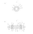
- FIG. 1 is a front view showing a first embodiment of a roll according to the present invention
- 1 is a cross-sectional view of a roll according to a first embodiment
- FIG. 1A is a side view showing a roll piece constituting the roll of the first embodiment
- FIG. 1B is a front view showing a base constituting the roll of the first embodiment.
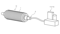
- FIG. 1 is a perspective view showing a state in which the roll of the first embodiment is connected to a suction device or a spray device
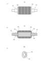
- FIG. 2A is a front view showing a second embodiment of a roll according to the present invention
- FIG. 2B is a cross-sectional view of the roll of the second embodiment
- FIG. 2C is a perspective view showing a part of a joint body constituting the roll of the second embodiment
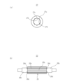
- FIG. 1A is a side view showing a roll piece constituting a roll of a second embodiment
- FIG. 1B is a front view showing a base constituting a roll of the second embodiment
- FIG. 1A is a front view showing a third embodiment of a roll according to the present invention
- FIG. 1B is a cross-sectional view of the roll of the third embodiment
- FIG. 1C is a perspective view showing a part of a joint body constituting the roll of the third embodiment
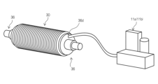
- FIG. 13 is a perspective view showing a state in which the roll of the third embodiment is connected to a suction device or a spray device.
- FIG. 4A is a front view showing a fourth embodiment of a roll according to the present invention
- FIG. 4B is a cross-sectional view of the roll according to the fourth embodiment.
- Fig. 1 is a front view showing a first embodiment of a roll according to the present invention
- Fig. 2 is a cross-sectional view of the roll of the first embodiment
- Fig. 3(a) is a side view showing a roll piece constituting the roll of the first embodiment
- Fig. 3(b) is a front view showing a base constituting the roll of the first embodiment
- Fig. 4 is a perspective view showing the roll of the first embodiment in communication with a suction device or an injection device. The first embodiment of the roll according to the present invention will be described below with reference to these figures.
- the roll 10 of the first embodiment is a roll for removing, squeezing, and cleaning liquids such as water, oil, or chemical components adhering to the surface to be cleaned of a steel plate, a non-ferrous metal plate, a resin plate, or a film-like member, using a suction device or a spray device, and has a roll portion 1 and a base 2.
- the base 2 has a body 5 that is arranged only at one or both ends 2a, 2b and has a fluid hole A3 formed in the outer peripheral surface 2c and a hollow shape portion 5a with a body fluid main pipe passage 4 that communicates with the fluid hole A3, and a coupling body 6 that is connected to at least one end 2a, 2b of the body 5 and communicates the body fluid main pipe passage 4 with the suction device 11a or the injection device 11b.
- the coupling body 6 is formed with a fluid main pipe passage 6a, which communicates with the suction device 11a or the injection device 11b.
- the coupling body 6 is composed of a coupling body main body 6b and a flange 6c, and the fluid main pipe passage 6a is formed in the coupling body main body 6b.
- the roll section 1 has multiple roll pieces 7, 7, 7... of a generally circular ring shape made of nonwoven fabric laminated on the base 2.
- the roll pieces 7 have cutouts 7a formed on the inner circumference.
- the cutouts 7a are laminated in a position that is continuous along the longitudinal direction of the base 2, forming a fluid capillary passage 8 between the base 2 and the roll pieces 7.
- the fluid capillary passage 8 extends to a position where it communicates with the fluid hole A3 of the base 2, and the fluid capillary passage 8 extends to a position where it communicates with the fluid main pipe passage 6a of the coupling body 6.
- the coupling body main body 6b has a fluid hole B6d formed so as to communicate with the fluid hole A3 of the base 2.
- the roll pieces 7 have two key grooves 7b formed in order to prevent rotation with the main body 5, and the main body 5 has a protrusion 5b formed in a position opposite the key groove 7b.
- the key groove 7b fits into the protrusion 5b to prevent rotation.
- the outer diameter and pitch of the fluid holes A3 are not particularly limited, but for example, it is desirable to set the outer diameter of the fluid holes A3 to about 1 to 8 mm and the pitch to about 20 to 100 mm. If the outer diameter of the fluid holes A3 is less than 1 mm, the diameter is too small to efficiently suck or spray liquid from the roll part 1, and if it exceeds 8 mm, the diameter is too large and the suction or spray force per hole is weak.
- the pitch of the fluid holes A3 is less than 20 mm, the number of fluid holes A3 is large and the rigidity of the ends 2a and 2b of the main body is low, and if it exceeds 100 mm, the number of fluid holes A3 is small and it is not possible to efficiently suck or spray liquid from the roll part 1. Furthermore, it is desirable to arrange the fluid holes A3 in a staggered pattern on the outer peripheral surface of the ends 2a and 2b of the main body, and by arranging them in a staggered pattern, it is possible to reduce the decrease in rigidity of the ends 2a and 2b of the main body 5.
- the fluid main pipe passage 6a of the joint body 6 provided at both ends of the base 2 can be simultaneously sucked or sprayed from both ends of the base 2 by connecting it to the suction device 11a or the spray device 11b, respectively, and the variation in the suction or spray of the liquid etc. impregnated in the entire roll part 1 can be reduced. Note that even if the fluid hole A3 is provided only at one end of the main body 5 and the fluid main pipe passage 6a is formed only on one side of the joint body 6 that communicates with the fluid hole A3, the effect of suction or spraying is exerted on the liquid etc. impregnated in the roll part 1, and this is included in the present invention. When the suction device 11a or the spray device 11b is operated, the liquid etc.
- the impregnated in the roll part 1 can be quickly and uniformly sucked or sprayed and discharged to the outside of the roll 10, so the liquid absorption saturation state of the roll part 1 is eliminated, the roll performance can be maintained, and the useful life of the roll 10 can be extended.
- the center of the body 5 of the base 2 has a higher rigidity than the ends 2a, 2b where the fluid holes A3 are formed, so that the roll portion 1 can be pressed firmly against the surface to be cleaned, enhancing the dam effect and the suction and discharge effect.
- the fluid capillary passage 8 to the suction device 11a or the spray device 11b, the liquid etc. impregnated in the roll portion 1 can be sucked or sprayed, so that the synergistic effect with the dam effect can improve the removal performance of the liquid etc. adhering to the surface to be cleaned.
- the dam effect here refers to the effect whereby by strongly pressing the roll part 1 against the surface to be cleaned, the cleaning liquid or other liquid is dammed up between the surface to be cleaned and the roll part 1, and then flows down from both ends of the roll 10 in the longitudinal direction, making it possible to remove most of the cleaning liquid or other liquid.
- any cleaning liquid or other liquid that cannot be removed by the dam effect is expelled to the outside as the roll part 1 is crushed and deformed, and when the crushed and deformed roll part 1 returns to its original shape, the external cleaning liquid or other liquid is sucked into the inside of the roll part 1 by capillary action, a phenomenon that is called the suction and discharge effect.
- the liquid saturation state in the roll part 1 is eliminated by suction or spraying, so that the roll part 1 can absorb the remaining liquid, etc. on the surface to be cleaned.
- a roll portion 1 having a surface hardness in the range of 75 degrees or more and 98 degrees or less. This allows the high hardness of the roll portion to press more firmly against the surface to be cleaned, further enhancing the dam effect, and the synergistic effect of suction or spraying can further improve the performance of removing liquids and the like adhering to the surface to be cleaned.
- the roll portion 1 has a low hardness and can flexibly come into contact with the surface to be cleaned while following its shape, further enhancing the suction and discharge effect, and the synergistic effect of suction or spraying can further improve the performance of removing liquids and the like adhering to the surface to be cleaned.
- the roll pieces 7 can be made of nonwoven fabric or synthetic resin porous bodies such as sponges, which are made up of fibers, binders that bond the fibers together, and voids that occupy the areas other than the fibers and binder.
- the nonwoven fabric can be manufactured by, for example, a chemical bonding method in which a polymeric elastomer containing a crosslinking agent is applied to a formed body in which multiple fibers are accumulated in a flat shape and entangled three-dimensionally, using methods such as spraying, immersion, and absorption, and then heated to bond the fibers.
- Other methods that can be used include a hydroentanglement method, a spunbond method, a meltblowing method, a fiberbond method, and a thermal bond method.
- the fibers that form the nonwoven fabric can be natural fibers such as cotton, hemp, linen, wool, silk, cashmere, and cellulose, semi-synthetic fibers such as rayon, cupra, acetate, triacetate, and promix, and synthetic resin fibers such as polyester, nylon, and acrylic, used alone or in combination.
- natural fibers such as cotton, hemp, linen, wool, silk, cashmere, and cellulose
- semi-synthetic fibers such as rayon, cupra, acetate, triacetate, and promix
- synthetic resin fibers such as polyester, nylon, and acrylic, used alone or in combination.
- the internal porosity (air porosity) of the synthetic resin porous body is preferably about 60-90%, and more preferably about 80-85%.
- a method for manufacturing a synthetic resin porous body can be used that involves, for example, immersing polyurethane in water and injecting carbon dioxide into the water to cause carbon dioxide foaming, thereby making the polyurethane porous with extremely fine air bubbles.
- the base body 5 is preferably configured to have a solid portion 9 in the center in the longitudinal direction. This increases the rigidity of the base body 5, allowing the roll portion 1 to be pressed more firmly against the surface to be cleaned, further enhancing the dam effect.
- FIG. 5(a) is a front view showing a second embodiment of a roll according to the present invention
- FIG. 5(b) is a cross-sectional view of the roll of the second embodiment
- FIG. 5(c) is a perspective view showing a part of a joint body constituting the roll of the second embodiment
- FIG. 6(a) is a side view showing a roll piece constituting the roll of the second embodiment
- FIG. 6(b) is a front view showing a base constituting the roll of the second embodiment.
- the roll 20 of the second embodiment differs from the roll 10 of the first embodiment in that the flange 26c constituting the joint body 26 also has a fluid main pipe passage 26a, and that the fluid hole A is not formed in the main body 25, and only the fluid hole B 26d is formed in the joint body main body 26b.
- the fluid capillary passage 8 can be formed over the entire longitudinal area of the roll part 1, the liquid absorption saturation state of the roll part 1 due to suction or spraying can be more efficiently eliminated.
- the main body 5 and the joint body main body 6b of the first embodiment are formed separately, the main body 25 and the joint body main body 26b of the second embodiment are formed integrally, and can be appropriately selected in consideration of manufacturing costs.
- key protrusions 27b are formed between adjacent notches 27a in the roll piece 27, and as shown in FIG. 6(b), a plurality of recessed grooves 25b are formed on the outer surface of the body 25 of the base 22 corresponding to the key protrusions 27b, from one end to the other end in the longitudinal direction.
- the key protrusions 27b fit into the recessed grooves 25b to prevent rotation.
- the roll piece 27 in FIG. 6(a) is formed of a dual structure in which multiple fiber bundles of ultrafine fibers are formed to form a nonwoven fabric, and a base of foamed polyurethane with ultrafine bubbles is formed around the fiber bundles.
- the ultrafine fibers are made of synthetic fibers such as nylon and polyester, and have a fineness of less than 1dTx.
- ultrafine fibers are called microfibers, and fiber bundles are called sea-island structures. With this configuration, liquids such as water, oil, or cleaning solutions can be more efficiently sucked in or sprayed due to the capillary action of the ultrafine fibers and the voids.
- FIG. 7(a) is a front view showing a third embodiment of a roll according to the present invention
- FIG. 7(b) is a cross-sectional view of the roll of the third embodiment
- FIG. 7(c) is a perspective view showing a part of a joint body constituting the roll of the third embodiment
- FIG. 8 is a perspective view showing the state in which the roll of the third embodiment is connected to a suction device or an injection device.
- the roll 30 of the third embodiment differs from the roll 10 of the first embodiment in that the main body 35 and the joint body main body 36b, 36b are integrally formed, that the fluid main pipe passage 36a is formed in the flange 36c constituting the joint body 36, that a fluid hole C36d is formed in the flange 36c, and that a seal member 37 is formed between the longitudinal side of the roll part 1 and the side of the flange 36c.
- This allows the main body 35 to maintain high rigidity, so that the roll part 1 can be pressed more strongly against the surface to be cleaned, and the dam effect can be further enhanced.
- the fluid capillary passage 8 can be formed over the entire longitudinal area of the roll part 1, the liquid absorption saturation state of the roll part 1 due to suction or spraying can be more efficiently eliminated. Furthermore, since the fluid main pipe passage 36a is formed only in the flange 36c, the manufacturing cost can be reduced. In addition, the fluid capillary passage 8 of the roll section 1 and the fluid main pipe passage 36a of the flange 36c are connected via a seal member 37, which prevents liquid or gas from leaking from the connection between the fluid capillary passage 8 and the fluid main pipe passage 36a.
- the distance to the fluid capillary passage 38 is shortened, enhancing the effect of suction or injection. Furthermore, of the flanges 36c, 36c formed on both ends of the roll 30, the fluid hole C36d in one flange 36c (the flange on the left side in Figure 7(b)) is blocked by a fitting lid 36e, ensuring the effect of suction or injection.
- FIG. 9(a) is a front view showing a fourth embodiment of a roll according to the present invention
- FIG. 9(b) is a cross-sectional view of the roll according to the fourth embodiment.
- the fourth embodiment of the roll according to the present invention will be described below using these figures.
- the roll 40 of the fourth embodiment differs from the roll 10 of the first embodiment in that the main body 45 does not have a solid portion in the center in the longitudinal direction, but is generally tubular with a hollow portion 45a formed inside. This allows the main body 45 to be generally tubular, which reduces manufacturing costs and improves the dam effect and suction/exhaust effect compared to a conventional roll with suction function in which a fluid hole is formed on the outer peripheral surface of the center part of the base.
- the roll according to the present invention is used as a roll for removing, squeezing, and cleaning liquids such as water, oil, and chemical components adhering to the surface to be cleaned of steel plates, non-ferrous metal plates, resin plates, or film-like members, using a suction device or spray device.
Landscapes
- Cleaning In General (AREA)
Abstract
【課題】 吸引装置による吸引効果を維持しつつ、ダム効果及び吸排効果を高めることができると共に、製造コストを低減させることができるロールを提供する。 【解決手段】ロール10は、ロール部1と、台座2と、を有し、台座2は、端部のみに配置され、外周面に形成された流体孔3と、流体孔3と連通する本体流体基管通路4を備えた中空形状部5aとを有する本体5と、本体5の端部と連接して設けられると共に、本体流体基管通路4と吸引装置11aとを連通させる継手体6とを有し、ロール部1は、台座2に積層される複数のロール片7を有し、ロール片7は、内周側に切欠き部7aが形成されているものであって、切欠き部7aは、台座2の長手方向に沿って連なる位置に積層されることで、台座2との間に流体細管通路8が形成され、流体細管通路8は、流体孔3と連通する位置まで延出している。
Description
本発明は、鋼板、非鉄金属板、樹脂板、ガラス、製紙、あるいはフィルム状のシートの被洗浄面に付着した水分、油分、あるいは薬品成分等の液体を除去、搾取、洗浄、吸引する為のロールに関するものである。
従来から、被洗浄面に付着した水分等を除去、搾取、洗浄、吸引する為のロールが知られている(特許文献1)。
特許文献1に記載のロールは、少なくとも一方が開口し、本体の軸方向に開設した中空部及びこの中空部に連通する透孔を、その本体周面に多数開設した筒状の軸本体と、この軸本体の両端に一体に形成した貫通孔を有する軸受部と、前記軸本体にフランジを介して不織布と、この不織布と異質材料でなるロール本体構成部材とを設けて圧着状に多数枚重畳したロール本体とからなるものであり、ロールに連通する真空ポンプ等を備えた吸引装置によって、ロールに含侵された水分等を外部に排出する構成としている。
上記特許文献1に記載のロール等に使用される筒状の軸本体は、耐久性を考慮して通常金属で作製されており、大径の中空部と周面の透孔を形成するための製造コストは嵩むものであった。また、軸本体は、ロール本体の軸中心に設けられた貫通孔に設置されることから、ロール本体を構成するロール片が柔らかい材料や硬度が低い材料で形成されている場合は、軸本体から離れている外周側が被洗浄面との当接時に生じる応力によって変形し易く、軸方向に倒れ易く、ダム効果や吸排効果が低くなるという課題を有していた。
本発明は、前記従来の課題を解決するものであり、吸引装置による吸引効果を維持しつつ、ダム効果及び吸排効果を高めることができると共に、製造コストを低減させることができるロールを提供することを目的とする。
前記従来の課題を解決するために、請求項1の発明は、鋼板、非鉄金属板、樹脂板、あるいはフィルム状の部材の被洗浄面に付着した水分、油分、あるいは薬品成分等の液体を、吸引装置又は噴射装置を用いて除去、搾取、洗浄する為のロールにおいて、前記ロールは、ロール部と、台座と、を有し、前記台座は、一方又は両方の端部のみに配置され、外周面に形成された流体孔と、該流体孔と連通する本体流体基管通路を備えた中空形状部と、を有する本体と、前記本体の少なくとも一方の端部と連接して設けられると共に、前記本体流体基管通路と前記吸引装置又は噴射装置とを連通させる継手体と、を有し、前記ロール部は、前記台座に積層される不織布からなる概円環状の複数のロール片を有し、前記ロール片は、内周側に切欠き部が形成されているものであって、前記切欠き部は、前記台座の長手方向に沿って連なる位置に積層されることで、前記台座との間に流体細管通路が形成され、前記流体細管通路は、前記台座の流体孔と連通する位置まで延出していることを特徴としている。
請求項1の発明では、流体孔を台座の本体の外周面であって、一方又は両方の端部のみに配置していることから、台座の本体の中央部は端部と比べて剛性が高く、被洗浄面にロール部を強く押し当てることができるため、被洗浄面に付着した液体等に対するダム効果及び吸排効果を高めることができる。また、吸引装置又は噴射装置と連通させた本体流体基管通路と、この本体流体基管通路と流体孔を介して連通している流体細管通路とによって、ロール部内に含浸されている液体等を吸引又は噴射させることができるため、ダム効果との相乗効果により、被洗浄面に付着した液体等の除去性能を向上させることができる。また、ダム効果によりせき止めた被洗浄面上の液体等を、効率よくロール部に吸収させることができるため、被洗浄面上に液体等が残ることを低減させることができる。
請求項2の発明は、鋼板、非鉄金属板、樹脂板、あるいはフィルム状の部材の被洗浄面に付着した水分、油分、あるいは薬品成分等の液体を、吸引装置又は噴射装置を用いて除去、搾取、洗浄する為のロールにおいて、前記ロールは、ロール部と、台座と、を有し、前記台座は、本体と、該本体の端部と連接して設けられると共に、前記吸引装置又は噴射装置と連通する流体基管通路が形成された継手体と、を有し、前記ロール部は、前記台座に積層される不織布からなる概円環状の複数のロール片を有し、前記ロール片は、内周側に切欠き部が形成されているものであって、前記切欠き部は、前記台座の長手方向に沿って連なる位置に積層されることで、前記台座との間に流体細管通路が形成され、前記流体細管通路は、前記継手体の流体基管通路と連通する位置まで延出していることを特徴としている。
請求項2の発明では、台座の継手体に流体基管通路が形成されており、この流体基管通路と流体細管通路とが連通していることから、台座の本体の剛性を高くすることができ、被洗浄面にロール部を強く押し当てることができるため、被洗浄面に付着した液体等に対するダム効果及び吸排効果を高めることができる。また、吸引装置又は噴射装置と連通させた流体基管通路と、この流体基管通路と連通している流体細管通路とによって、ロール部内に含浸されている液体等を吸引又は噴射させることができるため、ダム効果との相乗効果により、被洗浄面の液体等に対する除去性能を向上させることができる。また、ダム効果によりせき止めた被洗浄面上の液体等を、効率よくロール部に吸収させることができるため、被洗浄面上に液体等が残ることを低減させることができる。
請求項3の発明は、請求項2の発明において、流体細管通路と流体基管通路とは、シール部材を介して連結されていることを特徴としている。これにより、流体細管通路と流体基管通路の連結部分から液体が漏れるのを防ぐことができる。
請求項4の発明は、請求項1~3のいずれかの発明において、ロール部の硬度は、75度以上98度以下の範囲であることを特徴としている。これにより、高い硬度のロール部により被洗浄面を一層強く押し当てることができ、更にダム効果を高めることができる。
請求項5の発明は、請求項1~3のいずれかの発明において、台座の本体は、長手方向の中央に中実形状部を有していることを特徴としている。これにより、台座の本体の剛性を高くすることができ、被洗浄面にロール部を一層強く押し当てることができ、更にダム効果を高めることができる。
請求項1及び2のロールの発明は、被洗浄面にロール部を強く押し当てることができ、ダム効果及び吸排効果を高めることができる。また、流体細管通路と吸引装置又は噴射装置とを連通させることによって、ロール部内に含浸されている液体等を吸引又は噴射させることができるため、ダム効果との相乗効果により、被洗浄面の液体等に対する除去性能を向上させることができる。また、請求項3の発明は、流体細管通路と流体基管通路の連結部分から液体が漏れるのを防ぐことができる。
請求項4及び5の発明は、被洗浄面にロール部を一層強く押し当てることができ、ダム効果を高めることができる。
以下、本発明の実施形態について、図面を参照しながら説明する。なお、この実施の形態によって本発明が限定されるものではない。図1は、本発明に係るロールの第1実施形態を示す正面図であり、図2は、第1実施形態のロールの断面図である。また、図3(a)は、第1実施形態のロールを構成するロール片を示す側面図であり、図3(b)は、第1実施形態のロールを構成する台座を示す正面図である。また、図4は、第1実施形態のロールを吸引装置又は噴射装置と連通させた状態を示す斜視図である。これらの図を用いて本発明に係るロールの第1実施形態について以下に説明する。
第1実施形態のロール10は、鋼板、非鉄金属板、樹脂板、あるいはフィルム状の部材の被洗浄面に付着した水分、油分、あるいは薬品成分等の液体を、吸引装置又は噴射装置を用いて除去、搾取、洗浄する為のロール10であり、ロール部1と、台座2とを有している。
台座2は、一方又は両方の端部2a、2bのみに配置され、外周面2cに形成された流体孔A3と、流体孔A3と連通する本体流体基管通路4を備えた中空形状部5aとを有する本体5と、本体5の少なくとも一方の端部2a、2bと連接して設けられると共に、本体流体基管通路4と吸引装置11a又は噴射装置11bとを連通させる継手体6とを有している。尚、継手体6には、流体基管通路6aが形成されており、この流体基管通路6aは、吸引装置11a又は噴射装置11bと連通している。尚、継手体6は、継手体本体6bとフランジ6cとから構成されており、流体基管通路6aは、継手体本体6bに形成されている。
ロール部1は、台座2に積層される不織布からなる概円環状の複数のロール片7、7、7・・・を有しており、ロール片7は、内周側に切欠き部7aが形成されているものであって、切欠き部7aは、台座2の長手方向に沿って連なる位置に積層されることで、台座2との間に流体細管通路8が形成され、流体細管通路8は、台座2の流体孔A3と連通する位置まで延出していると共に、流体細管通路8は、継手体6の流体基管通路6aと連通する位置まで延出している。尚、継手体本体6bには、台座2の流体孔A3と連通するように、流体孔B6dが形成されている。また、ロール片7には、本体5との回り止めの為のキー溝7bが2か所に形成されており、このキー溝7bに対向する位置の本体5には、凸部5bが形成されている。そして、凸部5bにキー溝7bが嵌合することによって回り止めがなされる。
流体孔A3の外径やピッチについて、特に限定されるものではないが、例えば、流体孔A3の外径は1~8mm程度、ピッチは20~100mm程度に設定されるのが望ましい。流体孔A3の外径が1mm未満の場合、径が小さすぎてロール部1から効率よく液体を吸引又は噴射することができず、8mmを超える場合、径が大きすぎて一孔あたりの吸引力又は噴射力が弱くなる。また、流体孔A3のピッチが20mm未満の場合、流体孔A3の数が多く、本体の端部2a、2bの剛性が低くなり、100mmを超える場合、流体孔A3の数が少なく、ロール部1から効率よく液体を吸引又は噴射することができなくなる。さらに、流体孔A3は本体の端部2a、2bの外周面に千鳥状に配置することが望ましく、千鳥状に配置することで本体5の端部2a、2bの剛性の低下を軽減することができる。
台座2の両端に設けられる継手体6の流体基管通路6aは、それぞれに吸引装置11a又は噴射装置11bと連通させることで、台座2の両方の端部から同時に吸引又は噴射させることができ、ロール部1の全体に含浸された液体等に対する吸引又は噴射のバラつきを軽減させることができる。尚、本体5の一方の端部にのみ流体孔A3を設け、流体孔A3と連通する継手体6の片側にのみ流体基管通路6aを形成した場合も、ロール部1に含浸された液体等に対して吸引又は噴射の効果が発揮されるものであり、本発明に含まれる。吸引装置11a又は噴射装置11bを稼動させると、ロール部1に含浸されている液体等が、迅速、且つ均一に吸引又は噴射してロール10の外部に排出することができるため、ロール部1の吸液飽和状態が解消され、ロール性能を維持することができると共に、ロール10の耐用年数の長期化を図ることができる。
前述のように構成された第1実施形態のロール10は、台座2の本体5の中央部が、流体孔A3が形成されている端部2a、2bと比べて剛性が高いため、被洗浄面にロール部1を強く押し当てることができ、ダム効果及び吸排効果を高めることができる。また、流体細管通路8と吸引装置11a又は噴射装置11bとを連通させることによって、ロール部1内に含浸されている液体等を吸引又は噴射させることができるため、ダム効果との相乗効果により、被洗浄面に付着した液体等の除去性能を向上させることができる。
ここで、ダム効果とは、ロール部1を被洗浄面に強く押し当てることで、被洗浄面とロール部1との間に洗浄液等の液体がせき止められてロール10の長手方向の両端部側から流れ落とすことで洗浄液等の液体の大部分を取り除くことができる効果をいう。また、ダム効果で取り除けなかった洗浄液等の液体は、ロール部1が押しつぶされて変形することで外部に排出され、押しつぶされて変形したロール部1が元の形状に復元する時に外部の洗浄液等の液体を、ロール部1の内部に毛細管現象により吸い込むこととなる現象を吸排効果という。
また、第1実施形態のロール10は、ダム効果によりせき止められた洗浄液がロール10の長手方向の両端部側に流れ落ちることなく被洗浄面上に残った場合であっても、吸引又は噴射によりロール部1内の吸液飽和状態が解消されることで、ロール部1が被洗浄面上の液体等の残りを吸収することができる。
第1実施形態のロール10は、ロール部1の表面の硬度は、75度以上98度以下の範囲の硬度のものを使用するのが好ましい。これにより、高い硬度のロール部により被洗浄面を一層強く押し当てることができ、更にダム効果を高めることができると共に、吸引又は噴射による相乗効果により、被洗浄面に付着した液体等の除去性能を更に向上させることができる。一方で、ロール部1の表面の硬度を45度以上75度未満の範囲の硬度のものを使用した場合は、ロール部の硬度が低く、被洗浄面と柔軟に当接しつつ形状に倣うことで、更に吸排効果を高めることができると共に、吸引又は噴射による相乗効果により、被洗浄面に付着した液体等の除去性能を更に向上させることができる。
ロール片7は、繊維と、繊維同士を接着するバインダーと、繊維及びバインダー以外の部分を占める空隙部とで構成された不織布又はスポンジ等の合成樹脂多孔質体を使用することができる。また、不織布の製造方法は、例えば複数本の繊維を平板状に集積し3次元に絡合させた形成体にたいして、架橋剤を配合した高分子弾性体をスプレー、浸漬、吸収等の方法を用いて付着させ、加熱することにより繊維の間を結合させるケミカルボンド法を採用することができる。他には、水流絡合法、スパンボンド法、メルトブロー法、ファイバーボンド法やサーマルボンド法等を適宜採用することができる。また、不織布を形成する繊維には、綿、麻、リンネル、羊毛、絹、カシミヤ、セルロース等の天然繊維、レーヨン、キュプラ、アセテート、トリアセテート、プロミックス等の半合成繊維、ポリエステル、ナイロン、アクリル等の合成樹脂繊維が単独使用、あるいは併用される。
また、合成樹脂多孔質体の内部空隙率(気孔率)は約60~90%が好ましく、最適には約80~85%が更に好ましい。液体の粘性等により内部空隙率を適宜選択することで、液体の吸引効率と耐久性を共に向上させることができる。また、合成樹脂多孔質体の製造方法は、例えばポリウレタンを水中に浸漬させると共に、水中に二酸化炭素を注入し、炭酸発泡させることで極微細な気泡を有する多孔質化されたポリウレタンを採用することができる。
第1実施形態のロール10は、台座の本体5は、長手方向の中央に中実形状部9を有する構成とするのが好ましい。これにより、台座の本体5の剛性を高くすることができ、被洗浄面にロール部1を一層強く押し当てることができ、更にダム効果を高めることができる。
図5(a)は、本発明に係るロールの第2実施形態を示す正面図であり、図5(b)は、第2実施形態のロールの断面図、図5(c)は、第2実施形態のロールを構成する継手体の一部を示す斜視図である。また、図6(a)は、第2実施形態のロールを構成するロール片を示す側面図であり、図6(b)は、第2実施形態のロールを構成する台座を示す正面図である。これらの図を用いて本発明に係るロールの第2実施形態について以下に説明する。
第2実施形態のロール20と、第1実施形態のロール10と比較して異なる点は、継手体26を構成するフランジ26cにも流体基管通路26aが形成されている点と、流体孔Aが本体25に形成されておらず、流体孔B26dのみが継手体本体26bに形成されている点である。これにより、本体25が高い剛性を維持することができるため、被洗浄面にロール部1を一層強く押し当てることができ、更にダム効果を高めることができる。また、ロール部1の長手方向の全域に亘り流体細管通路8を形成することができるため、吸引又は噴射によるロール部1の吸液飽和状態を更に効率よく解消させることができる。尚、第1実施形態の本体5と継手体本体6bとは別体で形成されているが、第2実施形態は本体25と継手体本体26bとが一体的に形成されており、製造コストを考慮し適宜選択することができる。
また、第2実施形態のロール20は、図6(a)に示すように、ロール片27には、隣り合う切欠き部27aの間にキー凸部27bが形成されており、図6(b)に示すように、キー凸部27bに対応する台座22の本体25の外面には、長手方向の一方の端部から他方の端部にわたって複数の凹溝25bが形成されている。そして、凹溝25bにキー凸部27bが嵌合することによって回り止めがなされる。
図6(a)のロール片27は、複数本の極細繊維が集束した繊維束が複数個形成されて不織布が形成されると共に、繊維束の周りに、極微細な気泡を有する発泡化したポリウレタンの基部が形成されている二重構造体により形成されている。極細繊維は、ナイロン、ポリエステル等の合成繊維からなり、繊度は1dTx未満である。一般的に、極細繊維はマイクロファイバーと呼ばれ、繊維束は海島構造と呼ばれている。このように構成することによって、極細繊維による毛細管現象と空隙部とにより、水分、油分或いは洗浄液等の液体をより効率よく吸引又は噴射することができる。
図7(a)は、本発明に係るロールの第3実施形態を示す正面図であり、図7(b)は、第3実施形態のロールの断面図、図7(c)は、第3実施形態のロールを構成する継手体の一部を示す斜視図である。また、図8は、第3実施形態のロールを吸引装置又は噴射装置と連通させた状態を示す斜視図である。これらの図を用いて本発明に係るロールの第3実施形態について以下に説明する。
第3実施形態のロール30と、第1実施形態のロール10と比較して異なる点は、本体35と継手体本体36b、36bとが一体的に形成されている点と、継手体36を構成するフランジ36cに流体基管通路36aが形成されている点と、フランジ36cに流体孔C36dが形成されている点と、ロール部1の長手方向の側面とフランジ36cの側面との間にシール部材37が形成されている点である。これにより、本体35は高い剛性を維持することができるため、被洗浄面にロール部1を一層強く押し当てることができ、更にダム効果を高めることができる。また、ロール部1の長手方向の全域に亘り流体細管通路8を形成することができるため、吸引又は噴射によるロール部1の吸液飽和状態を更に効率よく解消させることができる。さらに、流体基管通路36aがフランジ36cにのみ形成されているため製造コストを低減させることができる。また、ロール部1の流体細管通路8とフランジ36cの流体基管通路36aとは、シール部材37を介して連結されており、これにより、流体細管通路8と流体基管通路36aの連結部分から液体や気体が漏れるのを防ぐことができる。
そして、フランジ36cに形成された流体孔C36dを直接、吸引装置11a又は噴射装置11bと連通させることによって、流体細管通路38との距離が短くなり、吸引又は噴射の効果を高めるようにしている。尚、ロール30の両端に形成されているフランジ36c、36cの内、一方のフランジ36c(図7(b)の左側のフランジ)の流体孔C36dは嵌合蓋36eにより経路を遮断することで、吸引又は噴射の効果を確実に発揮させている。
図9(a)は、本発明に係るロールの第4実施形態を示す正面図であり、図9(b)は、第4実施形態のロールの断面図である。これらの図を用いて本発明に係るロールの第4実施形態について以下に説明する。
第4実施形態のロール40と、第1実施形態のロール10と比較して異なる点は、本体45の長手方向の中央に中実形状部を有しておらず、略管形状であって内部に中空形状部45aが形成されている点である。これにより、本体45を略管状にすることができるため、製造コストを低減させることができると共に、台座の中央部の外周面に流体孔が形成されている従来の吸引機能を有するロールよりもダム効果及び吸排効果を高めることができる。
本発明に係るロールは、鋼板、非鉄金属板、樹脂板、あるいはフィルム状の部材の被洗浄面に付着した水分、油分、あるいは薬品成分等の液体を、吸引装置又は噴射装置を用いて除去、搾取、洗浄する為のロールとして利用される。
1 ロール部
2、22 台座
2a、2b 端部
2c 外周面
3 流体孔A
4 本体流体基管通路
5、25、35 本体
5a、45a 中空形状部
5b 凸部
6、26、36 継手体
6a、26a、36a 流体基管通路
6b、26b 継手体本体
6c、26c、36c フランジ
6d、26d 流体孔B
7、27 ロール片
7a、27a 切欠き部
7b キー溝
8、38 流体細管通路
9 中実形状部
10、20、30、40 ロール
11a 吸引装置
11b 噴射装置
25b 凹溝
27b キー凸部
36d 流体孔C
37 シール部材
2、22 台座
2a、2b 端部
2c 外周面
3 流体孔A
4 本体流体基管通路
5、25、35 本体
5a、45a 中空形状部
5b 凸部
6、26、36 継手体
6a、26a、36a 流体基管通路
6b、26b 継手体本体
6c、26c、36c フランジ
6d、26d 流体孔B
7、27 ロール片
7a、27a 切欠き部
7b キー溝
8、38 流体細管通路
9 中実形状部
10、20、30、40 ロール
11a 吸引装置
11b 噴射装置
25b 凹溝
27b キー凸部
36d 流体孔C
37 シール部材
Claims (5)
- 鋼板、非鉄金属板、樹脂板、あるいはフィルム状の部材の被洗浄面に付着した水分、油分、あるいは薬品成分等の液体を、吸引装置又は噴射装置を用いて除去、搾取、洗浄する為のロールにおいて、
前記ロールは、ロール部と、台座と、を有し、
前記台座は、
一方又は両方の端部のみに配置され、外周面に形成された流体孔と、該流体孔と連通する本体流体基管通路を備えた中空形状部と、を有する本体と、
前記本体の少なくとも一方の端部と連接して設けられると共に、前記本体流体基管通路と前記吸引装置又は噴射装置とを連通させる継手体と、を有し、
前記ロール部は、前記台座に積層される不織布からなる概円環状の複数のロール片を有し、前記ロール片は、内周側に切欠き部が形成されているものであって、
前記切欠き部は、前記台座の長手方向に沿って連なる位置に積層されることで、前記台座との間に流体細管通路が形成され、前記流体細管通路は、前記台座の流体孔と連通する位置まで延出していることを特徴とするロール - 鋼板、非鉄金属板、樹脂板、あるいはフィルム状の部材の被洗浄面に付着した水分、油分、あるいは薬品成分等の液体を、吸引装置又は噴射装置を用いて除去、搾取、洗浄する為のロールにおいて、
前記ロールは、ロール部と、台座と、を有し、
前記台座は、
本体と、該本体の端部と連接して設けられると共に、前記吸引装置又は噴射装置と連通する流体基管通路が形成された継手体と、を有し、
前記ロール部は、前記台座に積層される不織布からなる概円環状の複数のロール片を有し、前記ロール片は、内周側に切欠き部が形成されているものであって、
前記切欠き部は、前記台座の長手方向に沿って連なる位置に積層されることで、前記台座との間に流体細管通路が形成され、前記流体細管通路は、前記継手体の流体基管通路と連通する位置まで延出していることを特徴とするロール - 流体細管通路と流体基管通路とは、シール部材を介して連結されている請求項2に記載のロール
- ロール部の硬度は、75度以上98度以下の範囲である請求項1~3のいずれか1項に記載のロール
- 台座の本体は、長手方向の中央に中実形状部を有している請求項1~3のいずれか1項に記載のロール
Priority Applications (1)
| Application Number | Priority Date | Filing Date | Title |
|---|---|---|---|
| CN202480035757.6A CN121219088A (zh) | 2023-06-15 | 2024-06-13 | 辊 |
Applications Claiming Priority (2)
| Application Number | Priority Date | Filing Date | Title |
|---|---|---|---|
| JP2023-098610 | 2023-06-15 | ||
| JP2023098610A JP2024179624A (ja) | 2023-06-15 | 2023-06-15 | ロール |
Publications (1)
| Publication Number | Publication Date |
|---|---|
| WO2024257831A1 true WO2024257831A1 (ja) | 2024-12-19 |
Family
ID=93852188
Family Applications (1)
| Application Number | Title | Priority Date | Filing Date |
|---|---|---|---|
| PCT/JP2024/021512 Ceased WO2024257831A1 (ja) | 2023-06-15 | 2024-06-13 | ロール |
Country Status (3)
| Country | Link |
|---|---|
| JP (1) | JP2024179624A (ja) |
| CN (1) | CN121219088A (ja) |
| WO (1) | WO2024257831A1 (ja) |
Families Citing this family (1)
| Publication number | Priority date | Publication date | Assignee | Title |
|---|---|---|---|---|
| JP6833762B2 (ja) | 2017-06-22 | 2021-02-24 | キヤノン株式会社 | 金型、物品の製造方法、画像形成装置の製造方法、制御プログラム、および記録媒体 |
Citations (2)
| Publication number | Priority date | Publication date | Assignee | Title |
|---|---|---|---|---|
| JPS61392Y2 (ja) * | 1983-02-10 | 1986-01-08 | ||
| JP2012193787A (ja) * | 2011-03-16 | 2012-10-11 | Kowa Co Ltd | ロール及び洗浄装置 |
-
2023
- 2023-06-15 JP JP2023098610A patent/JP2024179624A/ja active Pending
-
2024
- 2024-06-13 WO PCT/JP2024/021512 patent/WO2024257831A1/ja not_active Ceased
- 2024-06-13 CN CN202480035757.6A patent/CN121219088A/zh active Pending
Patent Citations (2)
| Publication number | Priority date | Publication date | Assignee | Title |
|---|---|---|---|---|
| JPS61392Y2 (ja) * | 1983-02-10 | 1986-01-08 | ||
| JP2012193787A (ja) * | 2011-03-16 | 2012-10-11 | Kowa Co Ltd | ロール及び洗浄装置 |
Also Published As
| Publication number | Publication date |
|---|---|
| JP2024179624A (ja) | 2024-12-26 |
| CN121219088A (zh) | 2025-12-26 |
Similar Documents
| Publication | Publication Date | Title |
|---|---|---|
| WO2024257831A1 (ja) | ロール | |
| AU2007222723A1 (en) | Mop head and mop with such a mop head | |
| KR101676040B1 (ko) | 래티스 형상 기액 도통로 구조를 구비한 기능성 롤 | |
| JP5511044B2 (ja) | ロール | |
| JP5473112B2 (ja) | ロール及び洗浄装置 | |
| JP2009280883A5 (ja) | ||
| JP5455105B2 (ja) | ロール及び洗浄装置 | |
| CN212714098U (zh) | 溢流染色机 | |
| JP5709296B2 (ja) | ロール及び洗浄装置 | |
| JP3142589U (ja) | インクジェットプリンタ用の廃インク吸収体 | |
| JP2009041868A (ja) | ロール | |
| JP5594808B2 (ja) | ロール及び洗浄装置 | |
| JPH09226038A (ja) | 成形吸着体および立体構造の成形吸着体 | |
| JP2007301488A (ja) | ロール | |
| JP5279067B2 (ja) | ロールの排液方法と、この排液方法に使用するロール | |
| JP2023150536A (ja) | ロール | |
| JP2010276058A (ja) | ロール及び洗浄装置 | |
| CN217137921U (zh) | 适用于清洁机器人的用于擦拭待清洁工作面的拖布 | |
| WO2023136348A1 (ja) | ロール | |
| JP5447918B2 (ja) | ロール及び洗浄装置 | |
| CN211772984U (zh) | 一种金属、陶瓷纤维复合吸声板 | |
| JP5240961B2 (ja) | ロール及び洗浄装置 | |
| CN107997704A (zh) | 一种吸油性好的抹布 | |
| JPH0515856A (ja) | オイルプロセスライン等で採用される流体均一排除機能を備えた複合構造ゴムリンガーロール | |
| JP2008002521A (ja) | ロール |
Legal Events
| Date | Code | Title | Description |
|---|---|---|---|
| 121 | Ep: the epo has been informed by wipo that ep was designated in this application |
Ref document number: 24823446 Country of ref document: EP Kind code of ref document: A1 |
|
| WWE | Wipo information: entry into national phase |
Ref document number: 202517132276 Country of ref document: IN |
|
| WWP | Wipo information: published in national office |
Ref document number: 202517132276 Country of ref document: IN |
|
| NENP | Non-entry into the national phase |
Ref country code: DE |