WO2024257746A1 - 駆動輪及び台車 - Google Patents
駆動輪及び台車 Download PDFInfo
- Publication number
- WO2024257746A1 WO2024257746A1 PCT/JP2024/021132 JP2024021132W WO2024257746A1 WO 2024257746 A1 WO2024257746 A1 WO 2024257746A1 JP 2024021132 W JP2024021132 W JP 2024021132W WO 2024257746 A1 WO2024257746 A1 WO 2024257746A1
- Authority
- WO
- WIPO (PCT)
- Prior art keywords
- gear
- transmission
- drive
- shaft
- main
- Prior art date
- Legal status (The legal status is an assumption and is not a legal conclusion. Google has not performed a legal analysis and makes no representation as to the accuracy of the status listed.)
- Ceased
Links
Images










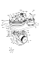


Classifications
-
- B—PERFORMING OPERATIONS; TRANSPORTING
- B62—LAND VEHICLES FOR TRAVELLING OTHERWISE THAN ON RAILS
- B62B—HAND-PROPELLED VEHICLES, e.g. HAND CARTS OR PERAMBULATORS; SLEDGES
- B62B3/00—Hand carts having more than one axis carrying transport wheels; Steering devices therefor; Equipment therefor
-
- B—PERFORMING OPERATIONS; TRANSPORTING
- B62—LAND VEHICLES FOR TRAVELLING OTHERWISE THAN ON RAILS
- B62D—MOTOR VEHICLES; TRAILERS
- B62D9/00—Steering deflectable wheels not otherwise provided for
-
- F—MECHANICAL ENGINEERING; LIGHTING; HEATING; WEAPONS; BLASTING
- F16—ENGINEERING ELEMENTS AND UNITS; GENERAL MEASURES FOR PRODUCING AND MAINTAINING EFFECTIVE FUNCTIONING OF MACHINES OR INSTALLATIONS; THERMAL INSULATION IN GENERAL
- F16H—GEARING
- F16H1/00—Toothed gearings for conveying rotary motion
- F16H1/02—Toothed gearings for conveying rotary motion without gears having orbital motion
- F16H1/04—Toothed gearings for conveying rotary motion without gears having orbital motion involving only two intermeshing members
- F16H1/06—Toothed gearings for conveying rotary motion without gears having orbital motion involving only two intermeshing members with parallel axes
-
- F—MECHANICAL ENGINEERING; LIGHTING; HEATING; WEAPONS; BLASTING
- F16—ENGINEERING ELEMENTS AND UNITS; GENERAL MEASURES FOR PRODUCING AND MAINTAINING EFFECTIVE FUNCTIONING OF MACHINES OR INSTALLATIONS; THERMAL INSULATION IN GENERAL
- F16H—GEARING
- F16H1/00—Toothed gearings for conveying rotary motion
- F16H1/02—Toothed gearings for conveying rotary motion without gears having orbital motion
- F16H1/04—Toothed gearings for conveying rotary motion without gears having orbital motion involving only two intermeshing members
- F16H1/12—Toothed gearings for conveying rotary motion without gears having orbital motion involving only two intermeshing members with non-parallel axes
Definitions
- the present invention relates to drive wheels and bogies.
- Patent Document 1 discloses a drive wheel and a bogie using the drive wheel.
- This drive wheel includes a first input shaft and a second input shaft arranged on the same axis, a first output shaft and a second output shaft arranged on a different axis, a first spur gear mechanism that transmits the rotational force of the first input shaft to the first output shaft, a second spur gear mechanism that transmits the rotational force of the second input shaft to the second output shaft, wheels connected to the axle, a rotating shaft that supports the wheels rotatably via the axle, a first power conversion mechanism that transmits the rotational force of the first output shaft to one end of the axle, and a second power conversion mechanism that transmits the rotational force of the second output shaft to the other end of the axle.
- Patent Document 2 also discloses a steerable drive mechanism.
- This drive mechanism includes a rotatable steering unit, wheels supported by the steering unit, a drive body that rotates around an axis on the center line of the steering unit, and an output shaft that is located eccentrically from the center axis of the steering unit and transmits the rotational force obtained from the drive body to the wheels.
- the drive body is a drive body in which a first drive unit that is driven in the forward direction and a second drive unit that is driven in the reverse direction are arranged coaxially.
- the output shaft includes a first output unit that receives the drive force from the first drive unit, and a second output unit that receives the drive force from a conversion unit that converts the rotation of the second drive unit to the forward direction, and is an output shaft that is constrained by the first output unit and the second output unit and transmits the rotational force obtained from the output unit to the wheels.
- the drive wheel described in Patent Document 1 and the drive mechanism described in Patent Document 2 are equipped with a differential omnidirectional movement mechanism. It is desirable to provide such a differential omnidirectional movement mechanism while simplifying its basic configuration as much as possible.
- This disclosure was made in consideration of the above problems, and aims to provide a drive wheel and bogie that can simplify the basic configuration while being equipped with a differential omnidirectional movement mechanism.
- a driving wheel includes a first input shaft and a second input shaft arranged on the same axis, a first output shaft arranged on a different axis from the first input shaft and the second input shaft, a first transmission mechanism including a first transmission drive gear and a main transmission driven gear to transmit the rotational force of the first input shaft to the first output shaft, a second transmission mechanism including a second transmission drive gear having the same number of teeth as the first transmission drive gear to transmit the rotational force of the second input shaft to the first output shaft, a main transmission driven intermediate gear that meshes with the second transmission drive gear to reverse the direction of rotation, and the main transmission driven gear, a rotatable main shaft to which a wheel is connected, a first power conversion mechanism that transmits the rotational force of the first output shaft to the main shaft, and a rotating shaft that supports the wheel so that it can turn via the main shaft.
- a preferred embodiment of the drive wheel is that the wheel is fixed to the main shaft.
- each of the transmission mechanisms is composed of helical gears.
- the second transmission mechanism includes an auxiliary main transmission driven intermediate gear consisting of a reverse-inclined helical gear with the same pitch diameter and number of teeth as the main transmission driven intermediate gear on the same axis, and an auxiliary main transmission driven gear consisting of a reverse-inclined helical gear with the same pitch diameter and number of teeth as the main transmission driven gear on the same axis, and
- a preferred embodiment of the drive wheel further comprises a second output shaft separate from the first output shaft, a third transmission mechanism including the first transmission drive gear to transmit the rotational force of the first input shaft to the second output shaft, an auxiliary transmission driven intermediate gear that meshes with the first transmission drive gear to reverse the direction of rotation, and an auxiliary transmission driven gear, a fourth transmission mechanism including the second transmission drive gear and the auxiliary transmission driven gear to transmit the rotational force of the second input shaft to the second output shaft, and a second power conversion mechanism that transmits the rotational force of the second output shaft to the main shaft.
- each of the transmission mechanisms is composed of a helical gear.
- the second transmission mechanism includes an auxiliary main transmission driven intermediate gear consisting of a helical gear with the same pitch diameter and number of teeth as the main transmission driven intermediate gear and a reverse inclination, and an auxiliary main transmission driven gear consisting of a helical gear with the same pitch diameter and number of teeth as the main transmission driven intermediate gear and a reverse inclination
- the third transmission mechanism includes an auxiliary secondary transmission driven intermediate gear consisting of a helical gear with the same pitch diameter and number of teeth as the secondary transmission driven intermediate gear and a reverse inclination, and an auxiliary secondary transmission driven gear consisting of a helical gear with the same pitch diameter and number of teeth as the main transmission driven gear and a reverse inclination, on the same axis.
- a desirable aspect of the drive wheel is that the axis of rotation of the wheel, which runs vertically and intersects with the axis of the main shaft, is shifted horizontally from the axis of the pivot shaft in a direction perpendicular to the axis of the main shaft.
- a desirable embodiment of the drive wheel includes an axle to which the wheel is fixed, and a rotational force transmission mechanism that transmits the rotational force of the main shaft to the axle, and the rotational force transmission mechanism displaces the rotational axis of the wheel, which runs vertically and intersects the axis of the axle, horizontally relative to the axis of the pivot shaft and perpendicular to the axis of the axle.
- a desirable embodiment of the drive wheel is one in which the rotational force transmission mechanism is a belt transmission mechanism.
- one embodiment of the bogie disclosed herein comprises any one of the drive wheels described above and a bogie body to which the drive wheel is attached.
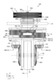
- FIG. 1 is a perspective view showing a basic configuration of a drive wheel according to a first embodiment.
- FIG. 2 is a plan view showing the basic configuration of the drive wheel of the first embodiment.
- FIG. 3 is a right side view showing the basic configuration of the drive wheel of the first embodiment.
- FIG. 4 is a front view showing the basic configuration of the drive wheel of the first embodiment.
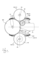
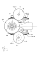
- FIG. 5 is a cross-sectional view showing a drive system for a drive wheel according to the first embodiment.
- FIG. 6 is a cross-sectional view showing a drive system for a drive wheel according to the first embodiment.
- FIG. 7 is a plan view showing a drive system for the drive wheels according to the first embodiment.
- FIG. 8 is a plan view showing a drive system for the drive wheels according to the first embodiment.
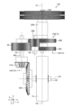
- FIG. 9 is a front view showing a drive system for the drive wheels according to the first embodiment.
- FIG. 10 is a rear view showing the drive system of the drive wheels according to the first embodiment.
- FIG. 11 is a schematic diagram showing a driving force transmission path of the driving wheels in the first embodiment.
- FIG. 12 is a front view showing the basic configuration of a drive wheel according to the second embodiment.
- FIG. 13 is a cross-sectional view showing a drive system for a drive wheel according to the second embodiment.
- FIG. 14 is a plan view showing a drive system for drive wheels according to the second embodiment.
- FIG. 15 is a plan view showing a drive system for drive wheels according to the second embodiment.
- FIG. 16 is a front view showing a drive system for drive wheels according to the second embodiment.
- FIG. 17 is a rear view showing a drive system for the drive wheels according to the second embodiment.
- FIG. 18 is a schematic diagram showing a driving force transmission path of a driving wheel according to the second embodiment.
- FIG. 19 is a front view showing a drive system for drive wheels according to the third embodiment.
- FIG. 20 is a rear view showing a drive system for the drive wheels according to the third embodiment.
- FIG. 21 is a front view showing a drive system for drive wheels according to the fourth embodiment.
- FIG. 22 is a rear view showing a drive system for the drive wheels according to the fourth embodiment.
- FIG. 23 is a perspective view showing the basic configuration of a drive wheel according to the fifth embodiment.
- FIG. 24 is a front view showing the basic configuration of a drive wheel according to the fifth embodiment.
- FIG. 25 is a right side view showing the basic configuration of a drive wheel according to the fifth embodiment.
- FIG. 26 is a schematic diagram illustrating an example of the configuration of a cart according to an embodiment.
- the present invention is not limited to this embodiment, and when there are multiple embodiments, it also includes configurations that combine the various embodiments. Furthermore, the components in the embodiments include those that a person skilled in the art can easily imagine, those that are substantially the same, and those that are within the so-called equivalent range.
- FIG. 26 is a schematic diagram showing an example of the configuration of a trolley in an embodiment.
- the trolley 100 includes a trolley body 101, a handle portion 102, four drive wheels 110 (120, 130, 140, 150), a power supply portion 104, and a control device 105.
- the trolley body 101 is, for example, a flat plate material, and has a rectangular shape in a plan view.
- a handle portion 102 is fixed to one side of the trolley body 101 in the longitudinal direction.
- Four drive wheels 110 are attached to the four corners of the back side of the trolley body 101.
- the four drive wheels 110 are rotatable and steerable.
- a power supply portion 104 and a control device 105 are attached to the back side of the trolley body 101 between the front and rear drive wheels 110.
- the control device 105 includes a computer system.
- the computer system includes a processor such as a CPU, and a memory such as a ROM or RAM.
- the control device 105 controls the drive wheels 110.
- the cart body 101 has a flat surface, on which transported objects can be placed.
- the cart 100 can be configured as an automatic guided vehicle (AGV).
- AGV automatic guided vehicle
- the cart 100 can also be configured as a device that travels by placing equipment along the flat surface of the cart body 101. Examples of such equipment include a hand lifter, a forklift, a picking robot, and medical equipment.
- the number and arrangement of the drive wheels 110 of the trolley 100 and the equipment are not limited to the above-mentioned configuration.
- the trolley 100 and the equipment may have a pair of drive wheels 110 attached to the rear side of the trolley 100 and a pair of driven wheels attached to the front side of the trolley 100.
- the trolley 100 and the equipment may have one drive wheel 110 and all the other wheels may be driven wheels.
- the trolley 100 and the equipment may have no driven wheels and all the wheels may be drive wheels 110.
- the trolley 100 and the equipment may have at least one drive wheel 110.
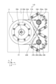
- FIG. 1 is a perspective view showing the basic configuration of the driving wheel of the first embodiment.
- FIG. 2 is a plan view showing the basic configuration of the driving wheel of the first embodiment.
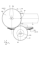
- FIG. 3 is a right side view showing the basic configuration of the driving wheel of the first embodiment.
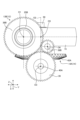
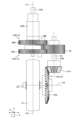
- FIG. 4 is a partially cutaway front view showing the basic configuration of the driving wheel of the first embodiment.
- FIG. 5 is a cross-sectional view (A-A cross-sectional view in FIG. 4) showing the drive system of the driving wheel of the first embodiment.
- FIG. 6 is a cross-sectional view (B-B cross-sectional view in FIG. 3) showing the drive system of the driving wheel of the first embodiment.
- FIG. 7 is a plan view showing the drive system of the driving wheel of the first embodiment.
- FIG. 8 is a plan view showing the drive system of the driving wheel of the first embodiment.
- FIG. 9 is a front view showing the drive system of the driving wheel of the first embodiment.
- FIG. 10 is a rear view showing the drive system of the driving wheel of the first embodiment.
- FIG. 11 is a schematic diagram showing the drive force transmission path of the driving wheel of the first embodiment.
- the first direction is referred to as the "front-rear direction X”
- the second direction is referred to as the “width direction Y”
- the third direction is referred to as the “up-down direction Z.”
- the front-rear direction X, width direction Y, and up-down direction Z are mutually perpendicular.
- the front-rear direction X typically corresponds to the direction along which the drive wheels 110 move straight.
- the drive wheel 110 has a body 10 that is fixed to the bogie body 101 of the bogie 100 as described above, and based on this body 10, a drive mechanism 11, a swivel unit 12, a transmission mechanism 13, a power conversion mechanism 14, and wheels 15 are provided.
- the main body 10 is formed in a plate shape with the plate surfaces facing up and down.
- the drive mechanism 11 inputs the rotational force and is mainly provided above the main body 10.
- the swivel unit 12 is mainly located below the main body 10.
- the transmission mechanism 13 transmits the rotational force input by the drive mechanism 11.
- the power conversion mechanism 14 transmits the rotational force of the transmission mechanism 13 to the wheels 15.
- the wheels 15 are single wheels that can rotate freely by the rotational force input via the drive mechanism 11, the transmission mechanism 13, and the power conversion mechanism 14, and can be steered by the swivel unit 12.
- the drive mechanism 11 has a first belt drive mechanism 22A as a first drive mechanism and a second belt drive mechanism 22B as a second drive mechanism.
- the first belt drive mechanism 22A includes a first drive unit 23A, a first drive pulley 24A, a first input shaft 25A, a first driven pulley 26A, and a first drive belt 27A.
- the first drive unit 23A is composed of a motor.
- the first drive unit 23A is fixed to the main body 10.
- the first drive unit 23A has a drive shaft 23Aa that protrudes above the main body 10 and extends in the vertical direction.
- the first drive pulley 24A is fixed to the drive shaft 23Aa.
- the first input shaft 25A is provided extending in the vertical direction so as to be parallel to the drive shaft 23Aa, and is supported so as to be rotatable around the axis O1.
- the first driven pulley 26A is fixed to a portion of the first input shaft 25A that protrudes above the main body 10.
- the first driven pulley 26A and the first driving pulley 24A are arranged side by side in a direction perpendicular to the first input shaft 25A and the driving shaft 23Aa.
- the first driving belt 27A is formed in a ring shape and is wound around the first driven pulley 26A and the first driving pulley 24A.
- the first driving pulley 24A rotates when driven by the first driving unit 23A, and this rotation is transmitted from the first driving pulley 24A to the first driven pulley 26A via the first driving belt 27A, causing the first input shaft 25A to rotate.
- the second belt drive mechanism 22B includes a second drive unit 23B, a second drive pulley 24B, a second input shaft 25B, a second driven pulley 26B, and a second drive belt 27B.
- the second drive unit 23B is composed of a motor.
- the second drive unit 23B is fixed to the main body 10.
- the second drive unit 23B has a drive shaft 23Ba that protrudes above the main body 10 and extends in the vertical direction.
- the second drive pulley 24B is fixed to the drive shaft 23Ba.
- the second drive pulley 24B is formed with the same diameter as the first drive pulley 24A.
- the second input shaft 25B is arranged to extend in the vertical direction so as to be parallel to the drive shaft 23Ba, and is supported so as to be freely rotatable around the axis O1.
- the second input shaft 25B is cylindrical and passes through the first input shaft 25A, and is disposed on the outside of the first input shaft 25A via a pair of intermediate bearings 44 (see FIG. 4) so as to rotate independently of the first input shaft 25A.
- the second driven pulley 26B is fixed to a portion of the second input shaft 25B that protrudes upward from the main body 10.
- the second driven pulley 26B is formed to have the same diameter as the first driven pulley 26A, and is located below the first driven pulley 26A.
- the second driven pulley 26B and the second driving pulley 24B are arranged side by side in a direction perpendicular to the second input shaft 25B and the driving shaft 23Ba.
- the second driving belt 27B is formed in an annular shape and is wound around the second driven pulley 26B and the second driving pulley 24B. Therefore, the second belt drive mechanism 22B drives the second drive unit 23B to rotate the second drive pulley 24B, and this rotation is transmitted from the second drive pulley 24B via the second drive belt 27B to the second driven pulley 26B, causing the second input shaft 25B to rotate.
- the swivel unit 12 includes a swivel shaft 35, a first support member 36A, and a second support member 36B.
- the swivel shaft 35 has an axis O1 at the center of the disk shape, and is rotatably supported by a circular through-hole 10a formed by penetrating the main body 10 in the vertical direction via a swivel bearing 45 (see FIG. 5). This allows the swivel shaft 35 to be supported so as to be rotatable relative to the main body 10 around the axis O1.
- the swivel shaft 35 is disposed so as to penetrate the first input shaft 25A of the first belt drive mechanism 22A in the vertical direction along the axis O1, and rotatably supports it via the first input bearing 43. Therefore, the first input shaft 25A is supported so as to be rotatable relative to the swivel shaft 35 around the axis O1, and is also supported so as to be rotatable relative to the main body 10 around the axis O1. In other words, the swivel shaft 35 is provided so as to be rotatable relative to the main body 10 regardless of the rotation of the first input shaft 25A.
- the driving wheel 110 of the embodiment can input a rotational force to the first input shaft 25A on the axis O1, which is the axis of rotation of the wheel 15.
- the swivel shaft 35 is disposed so as to face upwards, and rotatably supports the second input shaft 25B of the second belt drive mechanism 22B via the second input bearing 49.
- the second input shaft 25B is inserted through the first input shaft 25A and rotatably arranged on the outside of the first input shaft 25A via the intermediate bearing 44. Therefore, the second input shaft 25B is supported rotatably relative to the pivot shaft 35 around the axis O1 via the first input shaft 25A, and is also supported rotatably relative to the main body 10 around the axis O1.
- the pivot shaft 35 is rotatably arranged relative to the main body 10 regardless of the rotation of the second input shaft 25B. Therefore, the driving wheel 110 of the embodiment can input a rotational force to the second input shaft 25B on the axis O1, which is the pivot axis of the wheel 15.
- the first input shaft 25A, the second input shaft 25B, and the pivot shaft 35 are rotatably arranged coaxially along the axis O1.
- the swivel shaft 35 is provided at the bottom of the disk shape with a first support member 36A and a second support member 36B extending downward on either side of the width direction Y of the wheel 15.
- the wheel 15 is integrally provided with a main shaft 50 that extends in the width direction Y along an axis O2 perpendicular to the direction in which the axis O1 extends (the up-down direction Z).
- One end of the main shaft 50 along the axis O2 is rotatably supported by the first support member 36A via a wheel bearing 48 (see Figure 6), and the other end along the axis O2 is rotatably supported by the second support member 36B via a wheel bearing 48.
- the transmission mechanism 13 includes a first transmission gear mechanism (first transmission mechanism) 13A, a second transmission gear mechanism (second transmission mechanism) 13B, and a first output shaft 40A.
- the first transmission gear mechanism 13A includes a first transmission drive gear 38A, and a main transmission driven gear 39.
- the second transmission gear mechanism 13B includes a second transmission drive gear 38B, a main transmission driven intermediate gear 39B, and the main transmission driven gear 39.
- the first transmission gear mechanism 13A and the second transmission gear mechanism 13B are configured with spur gears.
- the first transmission drive gear 38A and the main transmission driven gear 39 are accommodated in the accommodation section 35a, as shown in Figures 5 and 6.
- the first transmission drive gear 38A is fixed to the first input shaft 25A.
- the first input shaft 25A is provided penetrating the rotating shaft 35, and the first transmission drive gear 38A is fixed inside the accommodation section 35a.
- the first input shaft 25A is also provided penetrating the rotating shaft 35 in the vertical direction along the axis O1, and is supported rotatably in the accommodation section 35a via the first input bearing 43. Therefore, the first transmission drive gear 38A rotates around the axis O1.
- the first transmission drive gear 38A meshes with the main transmission driven gear 39.
- the main transmission driven gear 39 is fixed to the first output shaft 40A.
- the first output shaft 40A is provided with a portion disposed in the accommodation section 35a and another portion protruding from the lower part of the rotating shaft 35.
- the first output shaft 40A is supported by the rotating shaft 35 via a pair of first output bearings 46 (see FIG. 6) and is supported so as to be freely rotatable about an axis O3 that is parallel to the axis O1.
- the second transmission drive gear 38B In the second transmission gear mechanism 13B, the second transmission drive gear 38B, the main transmission driven intermediate gear 39B, and the main transmission driven gear 39 are accommodated in the accommodation section 35a as shown in Figs. 5 and 6.
- the second transmission drive gear 38B is fixed to the second input shaft 25B.
- a portion of the second input shaft 25B enters the accommodation section 35a along the axis O1, and the second transmission drive gear 38B is fixed in the accommodation section 35a.
- the second input shaft 25B is disposed outside the first input shaft 25A via a pair of intermediate bearings 44, and is supported rotatably around the axis O1.
- the second input shaft 25B is supported rotatably on the rotating shaft 35 via the second input bearing 49 as described above. Therefore, the second transmission drive gear 38B rotates around the axis O1.
- the main transmission driven intermediate gear 39B meshes with the second transmission drive gear 38B.
- the main transmission driven intermediate gear 39B is supported in the housing portion 35a via an intermediate gear bearing 52, and is supported so as to be rotatable about an axis O6 parallel to the axis O1.
- the main transmission driven intermediate gear 39B also meshes with the main transmission driven gear 39. Therefore, the main transmission driven gear 39 is used in common in the configurations of the first transmission gear mechanism 13A and the second transmission gear mechanism 13B.
- the first transmission drive gear 38A of the first transmission gear mechanism 13A and the second transmission drive gear 38B of the second transmission gear mechanism 13B have the same pitch circle diameter and number of teeth.
- the power conversion mechanism 14 has a first conversion gear mechanism (first power conversion mechanism) 14A.
- the first conversion gear mechanism 14A is composed of a first conversion drive gear 41A and a first conversion driven gear 42A.
- the first conversion gear mechanism 14A is composed of a bevel gear.
- the first conversion drive gear 41A is fixed to the lower part of the first output shaft 40A. Therefore, the first conversion drive gear 41A rotates around the axis O3 together with the first output shaft 40A. Also, the first conversion driven gear 42A is fixed to one end of the main shaft 50. Therefore, the first conversion driven gear 42A rotates around the axis O2 together with the main shaft 50. And the first conversion drive gear 41A meshes with the first conversion driven gear 42A. Therefore, the first conversion gear mechanism 14A converts the rotation around the axis O3 of the first output shaft 40A into rotation around the axis O2 of the main shaft 50.
- the driving wheel 110 can rotate and steer the wheels 15 by rotating the first input shaft 25A and the second input shaft 25B with the drive mechanism 11. For example, by rotating the first input shaft 25A and rotating the second input shaft 25B in the opposite direction to the first input shaft 25A, and by making the number of rotations (rotational speed) transmitted to the first output shaft 40A the same, the wheels 15 can be rotated without steering. At this time, by making the number of rotations (rotational speed) of the first input shaft 25A and the second input shaft 25B different, the wheels 15 can be steered while rotating or stopped.
- the diameters of the first transmission drive gear 38A and the second transmission drive gear 38B are different, but as described above, the diameters and number of teeth of both are the same.
- the first transmission drive gear 38A rotates in the same direction
- the main transmission driven gear 39 meshing with the first transmission drive gear 38A rotates in the C direction.
- the first conversion drive gear 41A which is integrally provided with the main transmission driven gear 39 via the first output shaft 40A, rotates in the same direction.
- the first conversion driven gear 42A meshing with the first conversion drive gear 41A rotates in the D direction, causing the main shaft 50 integral with the first conversion driven gear 42A to rotate in the same direction.
- the second input shaft 25B rotates in the B1 direction, which is the opposite direction to the A1 direction
- the second transmission drive gear 38B rotates in the same direction
- the main transmission driven intermediate gear 39B meshing with the second transmission drive gear 38B rotates in the B2 direction.
- the main transmission driven intermediate gear 39B rotates in the B2 direction
- the main transmission driven gear 39 meshing with the main transmission driven intermediate gear 39B rotates in the C direction.
- the main transmission driven gear 39 rotates in the C direction
- the first conversion drive gear 41A which is integrally provided via the first output shaft 40A
- the first conversion driven gear 42A meshing with the first conversion drive gear 41A rotates in the D direction, causing the main shaft 50, which is integral with the first conversion driven gear 42A, to rotate in the same direction.
- the rotation speed input from the main transmission driven intermediate gear 39B to the main transmission driven gear 39 becomes lower than the rotation speed input from the first transmission drive gear 38A to the main transmission driven gear 39. Then, in order to absorb the difference in rotation speed, the turning shaft 35 rotates by the rotation speed difference, and the wheels 15 are turned and steered. Also, when the rotation of the first input shaft 25A or the second input shaft 25B is stopped, the rotation speed input from the first transmission drive gear 38A to the main transmission driven gear 39 or the rotation speed input from the main transmission driven intermediate gear 39B to the main transmission driven gear 39 becomes zero, and the wheels 15 do not rotate, and the turning shaft 35 is turned to steer.
- the driving wheel 110 in the above-mentioned embodiment rotates the first input shaft 25A and the second input shaft 25B arranged on the same axis in opposite directions (A1 direction and B1 direction), and in order to transmit these rotations to the main transmission driven gear 39 provided on the first output shaft 40A in the same direction (C direction), a main transmission driven intermediate gear 39B is provided that reverses the rotation (B1 direction) of the second transmission drive gear 38B (B2 direction). If an odd number of main transmission driven intermediate gears 39B are engaged between the second transmission drive gear 38B and the main transmission driven gear 39, the second transmission drive gear 38B can rotate (B1 direction) in the opposite direction (B2 direction) and then transmit it to the main transmission driven gear 39 in the same direction (C direction). Therefore, in the above-mentioned embodiment, the main transmission driven intermediate gear 39B is described as being one, but there may be more than one as long as there is an odd number.
- the drive wheel 110 of the embodiment has a rotation position detection unit, although this is not shown in the figure.
- the rotation position detection unit is provided in the main body 10, and detects the rotation position of the rotation shaft 35, i.e., the rotation position of the rotation unit 12 relative to the main body 10.
- the detection signal of the detector is input to the control device 105 of the cart (equipment) 100.
- the control device 105 can control the rotation of the drive wheel 110.
- the driving wheel 110 of the embodiment includes a first input shaft 25A and a second input shaft 25B arranged on the same axis, a first output shaft 40A arranged on a different axis from the first input shaft 25A and the second input shaft 25B, a first transmission gear mechanism (first transmission mechanism) 13A including a first transmission drive gear 38A and a main transmission driven gear 39 for transmitting the rotational force of the first input shaft 25A to the first output shaft 40A, and a first transmission drive gear 38A and a main transmission driven gear 39 for transmitting the rotational force of the second input shaft 25B to the first output shaft 40A.
- first transmission gear mechanism first transmission mechanism 13A including a first transmission drive gear 38A and a main transmission driven gear 39 for transmitting the rotational force of the first input shaft 25A to the first output shaft 40A
- first transmission drive gear 38A and a main transmission driven gear 39 for transmitting the rotational force of the second input shaft 25B to the first output shaft 40A.
- second transmission drive gear 38B having the same number of teeth as the first output shaft 40A
- main transmission driven intermediate gear 39B that meshes with the second transmission drive gear 38B to reverse the direction of rotation
- second transmission gear mechanism 13B including the main transmission driven gear 39, a rotatable main shaft 50 to which the wheels 15 are connected, a first conversion gear mechanism (first power conversion mechanism) 14A that transmits the rotational force of the first output shaft 40A to the main shaft 50, and a rotating shaft 35 that supports the wheels 15 so that they can rotate via the main shaft 50.
- This driving wheel 110 has a differential omnidirectional movement mechanism. That is, in the driving wheel 110, the rotational force of the first input shaft 25A is transmitted to the first output shaft 40A via the first transmission gear mechanism 13A, the rotational force of the second input shaft 25B is transmitted to the first output shaft 40A via the second transmission gear mechanism 13B, and is transmitted from the first output shaft 40A to the main shaft 50 via the first conversion gear mechanism 14A.
- This driving wheel 110 can switch between the rotation of the wheels 15 connected to the main shaft 50 and the steering of the wheels 15 by adjusting the rotation speed of the first input shaft 25A and the second input shaft 25B.
- this drive wheel 110 transmits the rotational force of the first input shaft 25A and the second input shaft 25B to the first output shaft 40A. Furthermore, this drive wheel 110 transmits the rotational force transmitted by the first conversion gear mechanism 14A to the first output shaft 40A to the main shaft 50. Therefore, in the prior art (for example, Patent Document 1), the rotational force of the first input shaft is transmitted to the first output shaft via a first transmission mechanism, and the rotational force of the second input shaft is transmitted to the second output shaft via a second transmission mechanism, but this drive wheel 110 is configured so that the rotational forces of the first input shaft 25A and the second input shaft 25B are both transmitted to the first output shaft 40A.
- both the first transmission gear mechanism 13A and the second transmission gear mechanism 13B include a main transmission driven gear 39, and the same functions as the conventional first output section and second output section are provided by a single main transmission driven gear 39, so that the cost of procuring and assembling parts can be reduced, and the failure rate can be reduced by reducing the number of parts.
- the wheel 15 is fixed to the main shaft 50.
- the rotation axis O5 of the wheel 15, which intersects with the axis O2 of the main shaft 50 and runs vertically, is shifted horizontally relative to the axis O1 of the swivel shaft 35 and perpendicular to the axis O2 of the main shaft 50.
- the bogie 100 of the embodiment also includes the drive wheels 110 described above and a bogie body 101 to which the drive wheels 110 are attached. Therefore, the basic structure of the bogie 100 can be simplified.
- Fig. 12 is a partially cut-away front view showing the basic configuration of a drive wheel of embodiment 2.
- Fig. 13 is a cross-sectional view (corresponding to the cross-sectional position B-B in Fig. 3) showing a drive system of the drive wheel of embodiment 2.
- Fig. 14 is a plan view showing the drive system of the drive wheel of embodiment 2.
- Fig. 15 is a plan view showing the drive system of the drive wheel of embodiment 2.
- Fig. 16 is a front view showing the drive system of the drive wheel of embodiment 2.
- Fig. 17 is a rear view showing the drive system of the drive wheel of embodiment 2.
- Fig. 18 is a schematic diagram showing a drive force transmission path of the drive wheel of embodiment 2.
- the driving wheel 120 of the second embodiment differs from the driving wheel 110 of the first embodiment described above mainly in that the transmission mechanism 13 further includes a third transmission gear mechanism (third transmission mechanism) 13C, a fourth transmission gear mechanism (fourth transmission mechanism) 13D, and a second output shaft 40B, and the power conversion mechanism 14 further includes a second conversion gear mechanism (second power conversion mechanism) 14B.
- the transmission mechanism 13 further includes a third transmission gear mechanism (third transmission mechanism) 13C, a fourth transmission gear mechanism (fourth transmission mechanism) 13D, and a second output shaft 40B
- the power conversion mechanism 14 further includes a second conversion gear mechanism (second power conversion mechanism) 14B.
- parts equivalent to those of the driving wheel 110 described above are given the same reference numerals and description thereof will be omitted.
- the third transmission gear mechanism 13C includes a first transmission drive gear 38A, a secondary transmission driven intermediate gear 39A, and a secondary transmission driven gear 39'.
- the fourth transmission gear mechanism 13D includes a second transmission drive gear 38B and the secondary transmission driven gear 39'.
- the third transmission gear mechanism 13C and the fourth transmission gear mechanism 13D are composed of spur gears, similar to the first transmission gear mechanism 13A and the second transmission gear mechanism 13B of the driving wheel 110.
- the first transmission drive gear 38A is configured similarly to the drive wheel 110 and is fixed to the first input shaft 25A.
- the secondary transmission driven intermediate gear 39A and the secondary transmission driven gear 39' are accommodated in the accommodation portion 35a as shown in FIG. 13.
- the secondary transmission driven intermediate gear 39A meshes with the first transmission drive gear 38A as shown in FIG. 14.
- the secondary transmission driven intermediate gear 39A is supported in the accommodation portion 35a via an intermediate gear bearing 54 and is supported rotatably about an axis O7 parallel to the axis O1.
- the secondary transmission driven gear 39' is fixed to the second output shaft 40B.
- a portion of the second output shaft 40B is disposed in the accommodation portion 35a and another portion protrudes from the lower part of the rotating shaft 35.
- the second output shaft 40B is supported by the rotating shaft 35 via a pair of second output bearings 53 (see FIG. 13) and is supported so as to be rotatable about an axis O4 parallel to the axis O1.
- the secondary transmission driven gear 39' meshes with the secondary transmission driven intermediate gear 39A.
- the second transmission drive gear 38B is configured similarly to the drive wheel 110 and is fixed to the second input shaft 25B. As shown in FIG. 15, the second transmission drive gear 38B also meshes with the secondary transmission driven gear 39'. Therefore, the secondary transmission driven gear 39' is used in common in the configurations of the third transmission gear mechanism 13C and the fourth transmission gear mechanism 13D.
- the first transmission drive gear 38A and the second transmission drive gear 38B have the same pitch circle diameter and number of teeth.
- the main transmission driven gear 39 and the secondary transmission driven gear 39' have the same pitch circle diameter and number of teeth.
- the main transmission driven intermediate gear 39B and the secondary transmission driven intermediate gear 39A have the same pitch circle diameter and number of teeth.
- the second conversion gear mechanism 14B is composed of a second conversion drive gear 41B and a second conversion driven gear 42B, as shown in Figures 12, 13, 16, and 17.
- the second conversion gear mechanism 14B is composed of a bevel gear, similar to the first conversion gear mechanism 14A of the driving wheel 110.
- the second conversion drive gear 41B is fixed to the lower part of the second output shaft 40B. Therefore, the second conversion drive gear 41B rotates around the axis O4 together with the second output shaft 40B.
- the second conversion driven gear 42B is fixed to the other end of the main shaft 50. Therefore, the second conversion driven gear 42B rotates around the axis O2 together with the main shaft 50.
- the second conversion drive gear 41B meshes with the second conversion driven gear 42B. Therefore, the second conversion gear mechanism 14B converts the rotation of the second output shaft 40B around the axis O4 into rotation of the main shaft 50 around the axis O2.
- the driving wheel 120 of the embodiment is arranged such that the rotation axis O5 of the wheel 15 along the vertical direction intersecting the axis O2 of the main shaft 50 is shifted (offset) in the horizontal direction (front-rear direction X) perpendicular to the axis O2 of the main shaft 50 with respect to the axis O1 of the turning shaft 35. Also, the driving wheel 120 of the embodiment is arranged such that the axis O3 of the first output shaft 40A and the axis O4 of the second output shaft 40B overlap the axis O2 of the main shaft 50 in a plan view.
- the first conversion drive gear 41A and the second conversion drive gear 41B have the same pitch circle diameter and number of teeth. Also, the first conversion driven gear 42A and the second conversion driven gear 42B have the same pitch circle diameter and number of teeth.
- the driving wheel 120 can rotate and steer the wheels 15 by rotating the first input shaft 25A and the second input shaft 25B with the drive mechanism 11. For example, by rotating the first input shaft 25A and rotating the second input shaft 25B in the opposite direction to the first input shaft 25A, and by making the number of rotations (rotational speed) transmitted to the first output shaft 40A and the second output shaft 40B the same, the wheels 15 can be rotated without steering. At this time, by making the number of rotations (rotational speed) of the first input shaft 25A and the second input shaft 25B different, the wheels 15 can be steered while rotating or stopped.
- the operation of the drive wheel 120 will be described.
- the first input shaft 25A of the drive wheel 120 rotates in the A1 direction
- the first transmission drive gear 38A rotates in the same direction
- the main transmission driven gear 39 meshing with the first transmission drive gear 38A rotates in the C direction
- the first conversion drive gear 41A which is integrally provided with the main transmission driven gear 39 via the first output shaft 40A, rotates in the same direction.
- the first conversion driven gear 42A meshing with the first conversion drive gear 41A rotates in the D direction, rotating the main shaft 50 integral with the first conversion driven gear 42A in the same direction.
- the first conversion drive gear 41A which is integrally provided via the first output shaft 40A, rotates in the same direction as above, and the first conversion driven gear 42A meshing with the first conversion drive gear 41A rotates in the D direction, causing the main shaft 50, which is integral with the first conversion driven gear 42A, to rotate in the same direction.
- the first transmission drive gear 38A rotates in the same direction
- the secondary transmission driven intermediate gear 39A meshing with the first transmission drive gear 38A rotates in the A2 direction
- the secondary transmission driven gear 39' meshing with the secondary transmission driven intermediate gear 39A rotates in the C' direction, which is the opposite direction to the C direction.
- the second conversion drive gear 41B which is integral with the secondary transmission driven gear 39' via the second output shaft 40B, rotates in the same direction.
- the second conversion driven gear 42B meshing with the second conversion drive gear 41B rotates in the D' direction, which is the same direction as the D direction, causing the main shaft 50, which is integral with the second conversion driven gear 42B, to rotate in the same direction.
- the second input shaft 25B rotates in the B1 direction, which is the opposite direction to the A1 direction
- the second transmission drive gear 38B rotates in the same direction
- the secondary transmission driven gear 39' meshing with the second transmission drive gear 38B rotates in the C' direction.
- the second conversion drive gear 41B which is integrally provided via the second output shaft 40B, rotates in the same direction
- the second conversion driven gear 42B meshing with the second conversion drive gear 41B rotates in the D' direction, rotating the main shaft 50, which is integral with the second conversion driven gear 42B, in the same direction.
- the drive wheel 120 in the above-mentioned embodiment rotates the first input shaft 25A and the second input shaft 25B arranged on the same axis in opposite directions (A1 direction and B1 direction), and in order to transmit these rotations to the main transmission driven gear 39 provided on the first output shaft 40A in the same direction (C direction), a main transmission driven intermediate gear 39B is provided that reverses the rotation (B1 direction) of the second transmission drive gear 38B (B2 direction). If an odd number of main transmission driven intermediate gears 39B are engaged between the second transmission drive gear 38B and the main transmission driven gear 39, the second transmission drive gear 38B can rotate (B1 direction) in the opposite direction (B2 direction) and then transmit it to the main transmission driven gear 39 in the same direction (C direction).
- the main transmission driven intermediate gear 39B is described as being one, but there may be more than one as long as there is an odd number.
- the driving wheel 120 in the above-mentioned embodiment rotates the first input shaft 25A and the second input shaft 25B arranged on the same axis in opposite directions (A1 direction and B1 direction), and transmits these rotations to the secondary transmission driven gear 39' provided on the second output shaft 40B in the same direction (C' direction).
- a secondary transmission driven intermediate gear 39A is provided that reverses the rotation (A1 direction) of the first transmission drive gear 38A (A2 direction).
- the secondary transmission driven intermediate gear 39A has been described as being one, but there may be a plurality of secondary transmission driven intermediate gears 39A as long as there is an odd number of them.
- the drive wheel 120 of the embodiment includes a first input shaft 25A and a second input shaft 25B arranged on the same axis, a first output shaft 40A arranged on a different axis from the first input shaft 25A and the second input shaft 25B, a first transmission mechanism 13A including a first transmission drive gear 38A and a main transmission driven gear 39 for transmitting the rotational force of the first input shaft 25A to the first output shaft 40A, and a first transmission mechanism 13B including a first transmission drive gear 38A and a main transmission driven gear 39 for transmitting the rotational force of the second input shaft 25B to the first output shaft 40A.
- first conversion gear mechanism first power conversion mechanism
- the driving wheel 120 of the embodiment further includes a second output shaft 40B on a different axis from the first output shaft 40A, a third transmission gear mechanism 13C including a first transmission drive gear 38A to transmit the rotational force of the first input shaft 25A to the second output shaft 40B, a secondary transmission driven intermediate gear 39A and a secondary transmission driven gear 39' that mesh with the first transmission drive gear 38A to reverse the direction of rotation, a fourth transmission gear mechanism 13D including a second transmission drive gear 38B and a secondary transmission driven gear 39' to transmit the rotational force of the second input shaft 25B to the second output shaft 40B, and a second power conversion mechanism 14B that transmits the rotational force of the second output shaft 40B to the main shaft 50.
- a third transmission gear mechanism 13C including a first transmission drive gear 38A to transmit the rotational force of the first input shaft 25A to the second output shaft 40B, a secondary transmission driven intermediate gear 39A and a secondary transmission driven gear 39' that mesh with the first transmission drive gear 38A to reverse the direction of rotation
- the driving wheel 120 has a differential omnidirectional movement mechanism. That is, in the driving wheel 120, the rotational force of the first input shaft 25A is transmitted to the first output shaft 40A via the first transmission gear mechanism 13A, the rotational force of the second input shaft 25B is transmitted to the first output shaft 40A via the second transmission gear mechanism 13B, and the first output shaft 40A is transmitted to the main shaft 50 via the first conversion gear mechanism 14A.
- the rotational force of the first input shaft 25A is transmitted to the second output shaft 40B via the third transmission gear mechanism 13C
- the rotational force of the second input shaft 25B is transmitted to the second output shaft 40B via the fourth transmission gear mechanism 13D
- the second output shaft 40B is transmitted to the main shaft 50 via the second conversion gear mechanism 14B.
- the driving wheel 110 can switch between the rotation of the wheels 15 connected to the main shaft 50 and the steering of the wheels 15 by adjusting the rotational speed of the first input shaft 25A and the second input shaft 25B.
- this drive wheel 120 the rotational force of the first input shaft 25A and the second input shaft 25B is transmitted to the first output shaft 40A and the second output shaft 40B. Furthermore, in this drive wheel 120, the first conversion gear mechanism 14A transmits the rotational force of the first output shaft 40A to the main shaft 50, and the second conversion gear mechanism 14B transmits the rotational force of the second output shaft 40B to the main shaft 50. Therefore, this drive wheel 120 can increase the transmission capacity from the first output shaft 40A and the second output shaft 40B to the main shaft 50 while simplifying the basic configuration like the drive wheel 110.
- the wheel 15 is fixed to the main shaft 50.
- the rotation axis O5 of the wheel 15, which intersects with the axis O2 of the main shaft 50 and runs vertically, is shifted horizontally relative to the axis O1 of the swivel shaft 35 and perpendicular to the axis O2 of the main shaft 50.
- the cart 100 can run and steer automatically, and can also be run and steered manually by an operator.
- the bogie 100 of the embodiment also includes the drive wheels 120 described above and a bogie body 101 to which the drive wheels 120 are attached. Therefore, the basic structure of the bogie 100 can be simplified.
- FIG. 19 is a front view showing a drive system for a drive wheel of the third embodiment.
- Fig. 20 is a rear view showing a drive system for a drive wheel of the third embodiment.
- the driving wheel 130 of this embodiment differs from the driving wheels 110 and 120 described above mainly in that the first transmission gear mechanism 13A and the second transmission gear mechanism 13B are configured with helical gears.
- the same parts as those of the driving wheels 110 and 120 described above are given the same reference numerals and the description is omitted.
- the first transmission drive gear 38A and the main transmission driven gear 39 are configured as meshing helical gears.
- the second transmission drive gear 38B, the main transmission driven intermediate gear 39B, and the main transmission driven gear 39 are configured as meshing helical gears.
- Other configurations of the drive wheel 130 include a configuration in which the third transmission gear mechanism 13C is configured with meshing helical gears of the first transmission drive gear 38A, the secondary transmission driven intermediate gear 39A, and the secondary transmission driven gear 39', and the fourth transmission gear mechanism 13D is configured with meshing helical gears of the second transmission drive gear 38B and the secondary transmission driven gear 39', as compared to the drive wheel 120 of embodiment 2.
- the drive wheel 130 has a first transmission gear mechanism 13A, a second transmission gear mechanism 13B, a third transmission gear mechanism 13C, and a fourth transmission gear mechanism 13D that are configured with helical gears.
- this drive wheel 130 uses helical gears in the transmission mechanism 13, which improves the meshing ratio (smoother meshing), improves strength (surface pressure strength), and improves noise reduction, resulting in better gear meshing.
- the wheel 15 is fixed to the main shaft 50.
- the rotation axis O5 of the wheel 15, which intersects with the axis O2 of the main shaft 50 and runs vertically, is shifted horizontally relative to the axis O1 of the swivel shaft 35 and perpendicular to the axis O2 of the main shaft 50.
- the cart 100 can run and steer automatically, and can also be run and steered manually by an operator.
- the bogie 100 of the embodiment also includes the drive wheels 130 described above and the bogie body 101 to which the drive wheels 130 are attached. As a result, the basic structure of the bogie 100 can be simplified and the gears can be meshed well.
- Fig. 21 is a front view showing a drive system of a drive wheel of the fourth embodiment.
- Fig. 22 is a rear view showing a drive system of a drive wheel of the fourth embodiment.
- the driving wheel 140 of the embodiment differs from the driving wheel 130 described above mainly in the configuration of the second transmission gear mechanism 13B. Also, the driving wheel 140 of the embodiment differs from the driving wheel 130 of the third embodiment mainly in the configuration of the third transmission gear mechanism 13C. In the following description of the driving wheel 140 of the fourth embodiment, the same parts as the driving wheels 110, 120, and 130 described above are given the same reference numerals and the description will be omitted.
- the second transmission gear mechanism 13B transmits the rotational force of the first input shaft 25A to the first output shaft 40A, and is composed of a second transmission drive gear 38B, a main transmission driven intermediate gear 39B, an auxiliary transmission driven intermediate gear 391B, an auxiliary main transmission driven gear 391, and a main transmission driven gear 39.
- the second transmission drive gear 38B, the main transmission driven intermediate gear 39B, and the main transmission driven gear 39 are composed of meshing helical gears similar to the drive wheel 120.
- the auxiliary transmission driven intermediate gear 391B is supported coaxially with the main transmission driven intermediate gear 39B and rotatably about the axis O6 together with the main transmission driven intermediate gear 39B.
- the auxiliary transmission driven intermediate gear 391B is also a reverse-inclined helical gear with the same pitch circle diameter and number of teeth as the main transmission driven intermediate gear 39B.
- the auxiliary main transmission driven gear 391 is fixed to the first output shaft 40A coaxially with the main transmission driven gear 39 and is supported so as to be rotatable about the axis O3.
- the auxiliary main transmission driven gear 391 is a reverse-inclined helical gear having the same pitch circle diameter and number of teeth as the main transmission driven gear 39.
- the auxiliary main transmission driven gear 391 meshes with the auxiliary transmission driven intermediate gear 391B.
- the rotational force of the second input shaft 25B is transmitted from the second transmission drive gear 38B through the main transmission driven intermediate gear 39B and through the main transmission driven gear 39 to the first output shaft 40A. Furthermore, in the second transmission gear mechanism 13B, the rotational force of the second input shaft 25B is transmitted from the auxiliary transmission driven intermediate gear 391B to the first output shaft 40A through the auxiliary main transmission driven gear 391.
- the meshing of the second transmission drive gear 38B, the main transmission driven intermediate gear 39B, and the main transmission driven gear 39 can achieve good meshing of the gears, but a load is generated in the thrust direction (direction along the axis).
- the drive wheel 140 is provided with the auxiliary transmission driven intermediate gear 391B and the auxiliary main transmission driven gear 391, which are reverse-inclined helical gears, and thus can offset and reduce the load in the thrust direction.
- the drive wheel 130 of embodiment 3 may include an auxiliary secondary transmission driven intermediate gear and an auxiliary secondary transmission driven gear, which are helical gears, in the third transmission gear mechanism 13C in place of the first transmission drive gear 38A, the secondary transmission driven intermediate gear 39A, and the secondary transmission driven gear 39', which are helical gears.
- the auxiliary secondary transmission driven intermediate gear is supported coaxially with the secondary transmission driven intermediate gear 39A and rotatably about the axis O7 together with the secondary transmission driven intermediate gear 39A.
- the auxiliary secondary transmission driven intermediate gear is a reverse-inclined helical gear that has the same pitch circle diameter and number of teeth as the secondary transmission driven intermediate gear 39A.
- the auxiliary secondary transmission driven gear is fixed to the second output shaft 40B coaxially with the secondary transmission driven gear 39' and is supported so as to be rotatable about the axis O4.
- the auxiliary secondary transmission driven gear is a reverse-inclined helical gear having the same pitch circle diameter and number of teeth as the secondary transmission driven gear 39'.
- the auxiliary secondary transmission driven gear meshes with the auxiliary secondary transmission driven intermediate gear.
- other forms of the drive wheel 140 can simplify the basic configuration like the drive wheel 110, while increasing the transmission capacity from the first output shaft 40A and the second output shaft 40B to the main shaft 50, and the helical gears improve the meshing of the gears while reducing the load in the thrust direction.
- the wheel 15 is fixed to the main shaft 50.
- the rotation axis O5 of the wheel 15, which intersects with the axis O2 of the main shaft 50 and runs vertically, is shifted horizontally relative to the axis O1 of the swivel shaft 35 and perpendicular to the axis O2 of the main shaft 50.
- the cart 100 can run and steer automatically, and can also be run and steered manually by an operator.
- the bogie 100 of the embodiment also includes the drive wheels 140 described above and the bogie body 101 to which the drive wheels 140 are attached. As a result, the basic structure of the bogie 100 can be simplified, and the load can be reduced while improving the meshing of the gears.
- FIG. 23 is a perspective view showing the basic configuration of a drive wheel of embodiment 5.
- Fig. 24 is a front view showing the basic configuration of a drive wheel of embodiment 5.
- Fig. 25 is a right side view showing the basic configuration of a drive wheel of embodiment 5.
- the driving wheel 150 of the fifth embodiment differs from the driving wheels 110, 120, 130, and 140 described above mainly in that it has a rotational force transmission mechanism 16.
- the same parts as those of the driving wheels 110, 120, 130, and 140 described above are given the same reference numerals and the description thereof is omitted.
- the rotational force transmission mechanism 16 as shown in Figures 23 to 25, transmits the rotational force of the main shaft 50 to the axle 37 to which the wheels 15 are fixed.
- the wheel 15 is integrally provided with an axle 37 that extends in the width direction Y along an axis O2 that is perpendicular to the direction in which the axis O1 extends (the up-down direction Z).
- One end of the axle 37 along the axis O2 is rotatably supported by a first support member 36A via a bearing (not shown), and the other end along the axis O2 is rotatably supported by a second support member 36B via a bearing (not shown).
- the first support member 36A and the second support member 36B are provided below the pivot shaft 35 so as to extend downward on both sides of the wheel 15 in the width direction Y.
- the main shaft 50 is supported by a pair of support parts 35b.
- the pair of support parts 35b extend downward from the lower part of the rotating shaft 35 in the vertical direction Z and are arranged facing each other in the width direction Y.
- the main shaft 50 is supported by the pair of support parts 35b so as to be freely rotatable about an axis O8 that is parallel to the axis O2 of the axle 37.
- the main shaft 50 supports the first support member 36A and the second support member 36B so that they can rotate freely around the axis O8.
- the first support member 36A and the second support member 36B are connected by the main shaft 50 and the axle 37. Therefore, the first support member 36A and the second support member 36B are connected by the main shaft 50 and the axle 37, and are arranged to be able to swing integrally in the front-to-rear direction X around the axis O8 of the main shaft 50.
- the first support member 36A and the second support member 36B are connected to the pivot shaft 35 via a pair of dampers 55.
- Each damper 55 is configured as a compression coil spring and has elasticity between one end and the other end, with one end supported by the pivot shaft 35 and the other end supported by the first support member 36A and the second support member 36B. Therefore, the first support member 36A and the second support member 36B are arranged to be swingable within a predetermined range in the fore-and-aft direction X around the axis O8 due to the length and elasticity between the one end and the other end of the damper 55.
- the wheel 15 supported by the first support member 36A and the second support member 36B via the axle 37 is arranged to be swingable within a predetermined range in the fore-and-aft direction X around the axis O8.
- the wheel 15 supported by the first support member 36A and the second support member 36B is arranged so that the rotation axis O5 of the wheel 15, which is aligned along the vertical direction intersecting the axis O2 of the axle 37, is shifted (offset) in the horizontal direction perpendicular to the axis O2 of the axle 37 in the left-right direction in FIG. 25 relative to the axis O1 of the pivot shaft 35.
- the rotational force transmission mechanism 16 is configured as a belt transmission mechanism including two pulleys 56 and a timing belt 57 wound around each pulley 56.
- One pulley 56 is fixed to the axle 37.
- the other pulley 56 is fixed to the main shaft 50. Therefore, the rotational force transmission mechanism 16 transmits the rotational force around the axis O8 of the main shaft 50 via the two pulleys 56 and the timing belt 57 as a rotational force around the axis O2 of the axle 37, thereby transmitting the driving force to the wheels 15 via the axle 37.
- This drive wheel 150 includes an axle 37 to which the wheel 15 is fixed, and a rotational force transmission mechanism 16 that transmits the rotational force of the main shaft 50 to the axle 37.
- the rotational force transmission mechanism 16 shifts the rotational axis O5 of the wheel 15, which intersects with the axis O2 of the axle 37 and runs vertically, horizontally relative to the axis O1 of the pivot shaft 35 and perpendicular to the axis O2 of the axle 37.
- the cart 100 can run and steer automatically, and can also be run and steered manually by an operator.
- the rotational force transmission mechanism 16 is a belt transmission mechanism.
- the bogie 100 of the embodiment also includes the drive wheels 150 described above and a bogie body 101 to which the drive wheels 150 are attached. Therefore, the basic structure of the bogie 100 can be simplified.
- the power conversion mechanism 14 has been described as a bevel gear, but this is not limited thereto.
- the power conversion mechanism 14 may be a helical gear, a worm gear, a crown gear, a universal joint, or the like.
Landscapes
- Engineering & Computer Science (AREA)
- General Engineering & Computer Science (AREA)
- Mechanical Engineering (AREA)
- Chemical & Material Sciences (AREA)
- Combustion & Propulsion (AREA)
- Transportation (AREA)
- Gear Transmission (AREA)
Abstract
差動式の全方向移動機構を備えつつ構成を簡素化すること。駆動輪110は、同軸上に配置される第一入力軸25A及び第二入力軸25Bと、第一入力軸25A及び第二入力軸25Bとは別軸上に配置される第一出力軸40Aと、第一入力軸25Aの回転力を第一出力軸40Aに伝達するように第一伝達駆動歯車38A及び主伝達従動歯車39を含む第一伝達機構13Aと、第二入力軸25Bの回転力を第一出力軸40Aに伝達するように第一伝達駆動歯車38Aと同歯数の第二伝達駆動歯車38B、第二伝達駆動歯車38Bに噛み合って回転方向を逆向きにする主伝達従動中間歯車39B、及び主伝達従動歯車39を含む第二伝達機構13Bと、車輪15が接続される回転自在な主軸50と、第一出力軸40Aの回転力を主軸50に伝達する第一変換歯車機構14Aと、主軸50を介して車輪15を旋回可能に支持する旋回軸35と、を備える。
Description
本発明は、駆動輪及び台車に関するものである。
特許文献1に駆動輪及び駆動輪を用いた台車について開示されている。この駆動輪は、同軸上に配置される第一入力軸及び第二入力軸と、別軸上に配置される第一出力軸及び第二出力軸と、第一入力軸の回転力を第一出力軸に伝達する第一平歯車機構と、第二入力軸の回転力を第二出力軸に伝達する第二平歯車機構と、車軸に連結される車輪と、車軸を介して車輪を旋回可能に支持する旋回軸と、第一出力軸の回転力を車軸の一端部に伝達する第一動力変換機構と、第二出力軸の回転力を車軸の他端部に伝達する第二動力変換機構と、を備えるものである。
また、特許文献2に操舵可能な駆動機構について開示されている。この駆動機構は、回転自在な操舵部と、この操舵部に支持される車輪と、上記操舵部の中心線上の軸回りに回転する駆動体と、上記操舵部の中心軸から偏心した位置に設けられ、上記駆動体から得られる回転力を上記車輪に伝達する出力軸とを備える。そして、上記駆動体は、正転方向に駆動される第一の駆動部及び逆転方向に駆動される第二の駆動部が同軸上に配置されてなる駆動体である。また、上記出力軸は、上記第一の駆動部から駆動力の伝達を受ける第一の出力部と、上記第二の駆動部の回転を正転方向に変換する変換部から駆動力の伝達を受ける第二の出力部とを備え、上記第一の出力部および第二の出力部に拘束され、かつ出力部から得られる回転力を車輪に伝達する出力軸である。
特許文献1に記載の駆動輪、及び特許文献2に記載の駆動機構は、差動式の全方向移動機構を備える。そして、このような差動式の全方向移動機構を備えつつ、その基本構成を極力簡素化することが望まれる。
本開示は、上記の課題に鑑みてなされたものであって、差動式の全方向移動機構を備えつつ基本構成を簡素化することのできる駆動輪及び台車を提供することを目的とする。
上記の目的を達成するための本開示の一態様の駆動輪は、同軸上に配置される第一入力軸及び第二入力軸と、前記第一入力軸及び前記第二入力軸とは別軸上に配置される第一出力軸と、前記第一入力軸の回転力を前記第一出力軸に伝達するように第一伝達駆動歯車及び主伝達従動歯車を含む第一伝達機構と、前記第二入力軸の回転力を前記第一出力軸に伝達するように前記第一伝達駆動歯車と同歯数の第二伝達駆動歯車、前記第二伝達駆動歯車に噛み合って回転方向を逆向きにする主伝達従動中間歯車、及び前記主伝達従動歯車を含む第二伝達機構と、車輪が接続される回転自在な主軸と、前記第一出力軸の回転力を前記主軸に伝達する第一動力変換機構と、前記主軸を介して前記車輪を旋回可能に支持する旋回軸と、を備える。
上記駆動輪の望ましい態様として、前記車輪が前記主軸に固定される。
上記駆動輪の望ましい態様として、各前記伝達機構は、はすば歯車にて構成される。さらに、上記駆動輪の望ましい態様として、前記第二伝達機構は、前記主伝達従動中間歯車に対して同軸上で同ピッチ円直径で同歯数で逆傾斜のはすば歯車からなる補助主伝達従動中間歯車と、前記主伝達従動歯車に対して同軸上で同ピッチ円直径で同歯数で逆傾斜のはすば歯車からなる補助主伝達従動歯車と、を含む。
上記駆動輪の望ましい態様として、前記第一出力軸とは別軸上の第二出力軸と、前記第一入力軸の回転力を前記第二出力軸に伝達するように前記第一伝達駆動歯車、前記第一伝達駆動歯車に噛み合って回転方向を逆向きにする副伝達従動中間歯車、及び副伝達従動歯車を含む第三伝達機構と、前記第二入力軸の回転力を前記第二出力軸に伝達するように前記第二伝達駆動歯車及び前記副伝達従動歯車を含む第四伝達機構と、前記第二出力軸の回転力を前記主軸に伝達する第二動力変換機構と、をさらに備える。さらに、上記駆動輪の望ましい態様として、各前記伝達機構は、はすば歯車にて構成される。さらに、上記駆動輪の望ましい態様として、前記第二伝達機構は、前記主伝達従動中間歯車に対して同軸上で同ピッチ円直径で同歯数で逆傾斜のはすば歯車からなる補助主伝達従動中間歯車と、前記主伝達従動歯車に対して同軸上で同ピッチ円直径で同歯数で逆傾斜のはすば歯車からなる補助主伝達従動歯車と、を含み、前記第三伝達機構は、前記副伝達従動中間歯車に対して同軸上で同ピッチ円直径で同歯数で逆傾斜のはすば歯車からなる補助副伝達従動中間歯車と、前記主伝達従動歯車に対して同軸上で同ピッチ円直径で同歯数で逆傾斜のはすば歯車からなる補助副伝達従動歯車と、を含む。
上記駆動輪の望ましい態様として、前記主軸の軸心に交差して鉛直方向に沿う前記車輪の回転軸心を、前記旋回軸の軸心に対して前記主軸の軸心に直交する水平方向にずれて配置する。
上記駆動輪の望ましい態様として、前記車輪が固定される車軸と、前記主軸の回転力を前記車軸に伝達する回転力伝達機構と、を含み、前記回転力伝達機構によって、前記車軸の軸心に交差して鉛直方向に沿う前記車輪の回転軸心を、前記旋回軸の軸心に対して前記車軸の軸心に直交する水平方向にずれて配置する。さらに、上記駆動輪の望ましい態様として、前記回転力伝達機構は、ベルト伝達機構からなる。
上記の目的を達成するための本開示の一態様の台車は、上述のいずれか1つの駆動輪と、前記駆動輪が取付けられる台車本体と、を備える。
本開示によれば、差動式の全方向移動機構を備えつつ基本構成を簡素化できる。
以下に図面を参照して、本開示に係る駆動輪及び台車の好適な実施形態を詳細に説明する。なお、この実施形態により本発明が限定されるものではなく、また、実施形態が複数ある場合には、各実施形態を組み合わせて構成するものも含むものである。また、実施形態における構成要素には、当業者が容易に想定できるもの、実質的に同一のもの、いわゆる均等の範囲のものが含まれる。
図26は、実施形態の台車の構成例を表す概略図である。
台車100は、台車本体101と、取手部102と、4個の駆動輪110(120,130,140,150)と、電源部104と、制御装置105と、を含む。
台車本体101は、例えば、平板材であり、平面視が矩形形状をなしている。台車本体101は、長手方向の一方側に取手部102が固定されている。台車本体101は、裏面側に4個の駆動輪110が四隅に装着される。4個の駆動輪110は、回転可能であると共に操舵可能となっている。また、台車本体101は、前後の駆動輪110の間の裏面に電源部104と制御装置105が装着されている。制御装置105は、コンピュータシステムを含む。コンピュータシステムは、CPUのようなプロセッサ、及びROMまたはRAMのようなメモリを含む。従って、台車100は、制御装置105が駆動輪110を制御する。
台車本体101は、平坦な面を構成することで、当該平坦な面に被運搬物を載せることができる。即ち、台車100は、無人搬送車(AGV:Automatic Guided Vehicle)として構成することができる。また、台車100は、台車本体101の平坦な面に沿って機材を配置することで走行する機器として構成することができる。機器としては、例えば、ハンドリフタや、フォークリフトや、ピッキングロボットや、医療機材等様々なものがある。
なお、台車100及び機器は、駆動輪110の数や配置について上述した構成に限定されるものではない。例えば、台車100及び機器は、上述した4輪の形態において、台車100の後方側に1対の駆動輪110を取り付け、台車100の前方側に1対の従動輪を取り付けてもよい。また、図には明示しないが、台車100及び機器は、3輪以上の形態において、駆動輪110が1つであって他の車輪が全て従動輪であってもよい。また、図には明示しないが、台車100及び機器は、3輪以上の形態において、従動輪を有さず全ての車輪が駆動輪110であってよい。即ち、台車100及び機器は、3輪以上の形態において、駆動輪110が少なくとも1つあればよい。
[駆動輪の実施形態1]
以下、駆動輪110について詳細に説明する。図1は、実施形態1の駆動輪の基本構成を表す斜視図である。図2は、実施形態1の駆動輪の基本構成を表す平面図である。図3は、実施形態1の駆動輪の基本構成を表す右側面図である。図4は、実施形態1の駆動輪の基本構成を表す一部を切り欠いた正面図である。図5は、実施形態1の駆動輪の駆動系を表す断面図(図4のA-A断面図)である。図6は、実施形態1の駆動輪の駆動系を表す断面図(図3のB-B断面図)である。図7は、実施形態1の駆動輪の駆動系を表す平面図である。図8は、実施形態1の駆動輪の駆動系を表す平面図である。図9は、実施形態1の駆動輪の駆動系を表す正面図である。図10は、実施形態1の駆動輪の駆動系を表す背面図である。図11は、実施形態1の駆動輪の駆動力伝達経路を表す模式図である。
以下、駆動輪110について詳細に説明する。図1は、実施形態1の駆動輪の基本構成を表す斜視図である。図2は、実施形態1の駆動輪の基本構成を表す平面図である。図3は、実施形態1の駆動輪の基本構成を表す右側面図である。図4は、実施形態1の駆動輪の基本構成を表す一部を切り欠いた正面図である。図5は、実施形態1の駆動輪の駆動系を表す断面図(図4のA-A断面図)である。図6は、実施形態1の駆動輪の駆動系を表す断面図(図3のB-B断面図)である。図7は、実施形態1の駆動輪の駆動系を表す平面図である。図8は、実施形態1の駆動輪の駆動系を表す平面図である。図9は、実施形態1の駆動輪の駆動系を表す正面図である。図10は、実施形態1の駆動輪の駆動系を表す背面図である。図11は、実施形態1の駆動輪の駆動力伝達経路を表す模式図である。
なお、以下の説明では、互いに交差する第一方向、第二方向、及び第三方向のうち、第一方向を「前後方向X」といい、第二方向を「幅方向Y」といい、第三方向を「上下方向Z」という。前後方向Xと幅方向Yと上下方向Zとは、相互に直交する。前後方向Xは、典型的には、駆動輪110が直進する方向に沿う方向に相当する。
駆動輪110は、上述したような台車100の台車本体101に固定される本体10を有し、この本体10を基に、駆動機構11と、旋回部12と、伝達機構13と、動力変換機構14と、車輪15と、が設けられる。
本体10は、上下に板面を向けた板状に形成される。駆動機構11は、回転力を入力するもので主に本体10の上方に設けられる。旋回部12は、主に本体10の下方に配置される。伝達機構13は、駆動機構11によって入力された回転力を伝達する。動力変換機構14は、伝達機構13の回転力を車輪15に伝達する。車輪15は、単輪であり、駆動機構11、伝達機構13、及び動力変換機構14を介して入力された回転力によって回転自在であると共に、旋回部12によって操舵可能となっている。
駆動機構11は、第一駆動機構としての第一ベルト駆動機構22Aと、第二駆動機構としての第二ベルト駆動機構22Bと、を有する。第一ベルト駆動機構22Aは、第一駆動部23A、第一駆動プーリ24A、第一入力軸25A、第一従動プーリ26A、及び第一駆動ベルト27Aを含む。第一駆動部23Aは、モータで構成される。第一駆動部23Aは、本体10に固定される。第一駆動部23Aは、本体10の上方に突出して上下方向に延びる駆動軸23Aaを有する。第一駆動プーリ24Aは、駆動軸23Aaに固定される。第一入力軸25Aは、駆動軸23Aaと平行となるように上下方向に延びて設けられ、軸心O1を中心として回転自在に支持される。第一従動プーリ26Aは、第一入力軸25Aの本体10の上方に突出した部分に固定される。第一従動プーリ26A及び第一駆動プーリ24Aは、第一入力軸25A及び駆動軸23Aaに直交する方向で並んで設けられる。第一駆動ベルト27Aは、環状に形成され、第一従動プーリ26A及び第一駆動プーリ24Aに掛け回される。従って、第一ベルト駆動機構22Aは、第一駆動部23Aの駆動により、第一駆動プーリ24Aが回転し、この回転が第一駆動プーリ24Aから第一駆動ベルト27Aを介して第一従動プーリ26Aに伝達されて第一入力軸25Aが回転する。
第二ベルト駆動機構22Bは、第二駆動部23B、第二駆動プーリ24B、第二入力軸25B、第二従動プーリ26B、及び第二駆動ベルト27Bを含む。第二駆動部23Bは、モータで構成される。第二駆動部23Bは、本体10に固定される。第二駆動部23Bは、本体10の上方に突出して上下方向に延びる駆動軸23Baを有する。第二駆動プーリ24Bは、駆動軸23Baに固定される。第二駆動プーリ24Bは、第一駆動プーリ24Aと同径に形成される。第二入力軸25Bは、駆動軸23Baと平行となるように上下方向に延びて設けられ、軸心O1を中心として回転自在に支持される。第二入力軸25Bは、円筒形状をなして第一入力軸25Aを挿通し、第一入力軸25Aとは独立して回転するように第一入力軸25Aの外側に1対の中間軸受44(図4参照)を介して配置される。第二従動プーリ26Bは、第二入力軸25Bの本体10の上方に突出した部分に固定される。第二従動プーリ26Bは、第一従動プーリ26Aと同径に形成され、第一従動プーリ26Aの下方に位置する。第二従動プーリ26B及び第二駆動プーリ24Bは、第二入力軸25B及び駆動軸23Baに直交する方向で並んで設けられる。第二駆動ベルト27Bは、環状に形成され、第二従動プーリ26B及び第二駆動プーリ24Bに掛け回される。従って、第二ベルト駆動機構22Bは、第二駆動部23Bを駆動することで、第二駆動プーリ24Bが回転し、この回転が第二駆動プーリ24Bから第二駆動ベルト27Bを介して第二従動プーリ26Bに伝達されて第二入力軸25Bが回転する。
旋回部12は、旋回軸35と、第一支持部材36Aと、第二支持部材36Bと、を含む。旋回軸35は、円板形状の中心を軸心O1とし、本体10において上下方向に貫通して形成された円形状の貫通部10aに旋回軸受45(図5参照)を介して回転自在に支持される。これにより、旋回軸35は、本体10に対して軸心O1を中心として相対的に回転可能に支持される。
旋回軸35は、図5に示すように、第一ベルト駆動機構22Aの第一入力軸25Aを軸心O1に沿って上下方向に貫通して配置し、第一入力軸受43を介して回転自在に支持する。従って、第一入力軸25Aは、旋回軸35に対して軸心O1を中心として相対的に回転可能に支持され、かつ本体10に対しても軸心O1を中心として相対的に回転可能に支持される。即ち、旋回軸35は、第一入力軸25Aの回転に関わらず、本体10に対して回転可能に設けられる。このため、実施形態の駆動輪110は、車輪15の旋回軸心である軸心O1上の第一入力軸25Aに回転力を入力することができる。また、旋回軸35は、第二ベルト駆動機構22Bの第二入力軸25Bを上方に向けて配置し、第二入力軸受49を介して回転自在に支持する。第二入力軸25Bは、上述したように、第一入力軸25Aを挿通し、第一入力軸25Aの外側に中間軸受44を介して回転自在に配置される。従って、第二入力軸25Bは、第一入力軸25Aを介し、旋回軸35に対して軸心O1を中心として相対的に回転可能に支持され、かつ本体10に対しても軸心O1を中心として相対的に回転可能に支持される。即ち、旋回軸35は、第二入力軸25Bの回転に関わらず、本体10に対して回転可能に設けられる。このため、実施形態の駆動輪110は、車輪15の旋回軸心である軸心O1上の第二入力軸25Bに回転力を入力することができる。このような構成により、第一入力軸25Aと第二入力軸25Bと旋回軸35とは、軸心O1に沿う同軸上に回転可能に配置される。
旋回軸35は、円板形状の下部で車輪15の幅方向Yの両側に第一支持部材36Aと第二支持部材36Bが下方に延出するように設けられる。車輪15は、軸心O1が延びる方向(上下方向Z)に直交する軸心O2に沿って幅方向Yに沿って延びる主軸50が一体に設けられる。主軸50は、軸心O2に沿う一端部が第一支持部材36Aに対して車輪軸受48(図6参照)を介して回転自在に支持されると共に、軸心O2に沿う他端部が第二支持部材36Bに対して車輪軸受48を介して回転自在に支持される。
伝達機構13は、図4から図9に示すように、第一伝達歯車機構(第一伝達機構)13Aと第二伝達歯車機構(第二伝達機構)13B、及び第一出力軸40Aを含む。第一伝達歯車機構13Aは、第一伝達駆動歯車38A、及び主伝達従動歯車39を含み構成される。第二伝達歯車機構13Bは、第二伝達駆動歯車38B、主伝達従動中間歯車39B、及び上記主伝達従動歯車39を含み構成される。実施形態の駆動輪110では、第一伝達歯車機構13Aと第二伝達歯車機構13Bは、平歯車にて構成される。
第一伝達歯車機構13Aにおいて、第一伝達駆動歯車38A、主伝達従動歯車39は、図5及び図6に示すように、収容部35aに収容される。第一伝達駆動歯車38Aは、第一入力軸25Aに固定される。第一入力軸25Aは、旋回軸35に貫通して設けられ、収容部35aの内部において第一伝達駆動歯車38Aが固定される。また、第一入力軸25Aは、軸心O1に沿って上下方向に旋回軸35を貫通して設けられ、収容部35aにおいて第一入力軸受43を介して回転自在に支持される。従って、第一伝達駆動歯車38Aは、軸心O1を中心として回転する。第一伝達駆動歯車38Aは、主伝達従動歯車39が噛み合う。主伝達従動歯車39は、第一出力軸40Aに固定される。第一出力軸40Aは、収容部35aに一部が配置されて他の一部が旋回軸35の下部に突出して設けられる。第一出力軸40Aは、1対の第一出力軸受46(図6参照)を介して旋回軸35に支持されて、軸心O1に平行な軸心O3を中心として回転自在に支持される。
第二伝達歯車機構13Bにおいて、第二伝達駆動歯車38B、主伝達従動中間歯車39B、主伝達従動歯車39は、図5及び図6に示すように、収容部35aに収容される。第二伝達駆動歯車38Bは、第二入力軸25Bに固定される。第二入力軸25Bは、軸心O1に沿ってその一部が収容部35aに入り込み、収容部35aにおいて第二伝達駆動歯車38Bが固定される。また、第二入力軸25Bは、上述したように第一入力軸25Aの外側に1対の中間軸受44を介して配置され、軸心O1を中心として回転自在に支持される。さらに、第二入力軸25Bは、上述したように旋回軸35において第二入力軸受49を介して回転自在に支持される。従って、第二伝達駆動歯車38Bは、軸心O1を中心として回転する。
主伝達従動中間歯車39Bは、第二伝達駆動歯車38Bが噛み合う。主伝達従動中間歯車39Bは、収容部35aにおいて中間歯車軸受52を介して支持されて、軸心O1に平行な軸心O6を中心として回転自在に支持される。また、主伝達従動中間歯車39Bは、主伝達従動歯車39にも噛み合う。従って、主伝達従動歯車39は、第一伝達歯車機構13Aと第二伝達歯車機構13Bの構成において共通に用いられる。
この伝達機構13において、第一伝達歯車機構13Aの第一伝達駆動歯車38Aと、第二伝達歯車機構13Bの第二伝達駆動歯車38Bとは、ピッチ円直径及び歯数が相互に同じである。
動力変換機構14は、図6、図9及び図10に示すように、第一変換歯車機構(第一動力変換機構)14Aを有する。第一変換歯車機構14Aは、第一変換駆動歯車41A、第一変換従動歯車42Aにより構成される。実施形態の駆動輪110では、第一変換歯車機構14Aは、傘歯車にて構成される。
第一変換駆動歯車41Aは、第一出力軸40Aの下部に固定される。従って、第一変換駆動歯車41Aは、第一出力軸40Aと共に軸心O3の廻りに回転する。また、第一変換従動歯車42Aは、主軸50の一端部に固定される。従って、第一変換従動歯車42Aは、主軸50と共に軸心O2の廻りに回転する。そして、第一変換駆動歯車41Aは、第一変換従動歯車42Aに噛み合う。従って、第一変換歯車機構14Aは、第一出力軸40Aの軸心O3の廻りの回転を、主軸50の軸心O2の廻りの回転に変換する。
また、図7及び図8に示すように、実施形態の駆動輪110は、主軸50の軸心O2に交差する鉛直方向に沿う車輪15の回転軸心O5が、旋回軸35の軸心O1に対して主軸50の軸心O2に直交する水平方向(前後方向X)にずれて(オフセットして)配置される。これにより、駆動輪110の鉛直方向サイズのコンパクト化を図っている。また、実施形態の駆動輪110は、平面視において、第一出力軸40Aの軸心O3が主軸50の軸心O2に重なって設けられる。これにより、主軸50への力の伝達が確実に行われる。
この駆動輪110は、駆動機構11によって第一入力軸25Aと第二入力軸25Bを回転することで車輪15の回転と操舵を行うことができる。例えば、第一入力軸25Aを回転し、第二入力軸25Bを第一入力軸25Aと逆方向に回転すると共に、第一出力軸40Aへ伝達する回転数(回転速度)を同じにすることで、車輪15を操舵せずに回転することができる。このとき、第一入力軸25Aと第二入力軸25Bの回転数(回転速度)を異ならせることで、車輪15を回転または停止した状態で操舵することができる。
ここで、駆動輪110の作動について図11に基づいて説明する。図11では、説明の便宜上、第一伝達駆動歯車38Aと第二伝達駆動歯車38Bの直径は異なっているが、前述説明の通り、両者の直径・歯数が同一である。図11に示すように、駆動輪110は、第一入力軸25AをA1方向に回転すると、第一伝達駆動歯車38Aが同方向に回転し、第一伝達駆動歯車38Aに噛み合う主伝達従動歯車39がC方向に回転する。主伝達従動歯車39がC方向に回転すると、主伝達従動歯車39に第一出力軸40Aを介して一体に設けられた第一変換駆動歯車41Aが同方向に回転する。すると、第一変換駆動歯車41Aに噛み合う第一変換従動歯車42AがD方向に回転し、第一変換従動歯車42Aと一体の主軸50を同方向に回転させる。一方、駆動輪110は、第二入力軸25BをA1方向と逆方向のB1方向に回転すると、第二伝達駆動歯車38Bが同方向に回転し、第二伝達駆動歯車38Bに噛み合う主伝達従動中間歯車39BがB2方向に回転する。主伝達従動中間歯車39BがB2方向に回転すると、主伝達従動中間歯車39Bに噛み合う主伝達従動歯車39がC方向に回転する。そして、主伝達従動歯車39がC方向に回転することで、上記と同様に第一出力軸40Aを介して一体に設けられた第一変換駆動歯車41Aが同方向に回転し、第一変換駆動歯車41Aに噛み合う第一変換従動歯車42AがD方向に回転して、第一変換従動歯車42Aと一体の主軸50を同方向に回転させる。
このとき、駆動輪110は、第一入力軸25Aの回転数に対して第二入力軸25Bの回転数を低下させると、主伝達従動中間歯車39Bから主伝達従動歯車39に入力する回転数が、第一伝達駆動歯車38Aから主伝達従動歯車39に入力する回転数より低くなる。すると、回転数差を吸収するために、その回転数差だけ旋回軸35が回転し、車輪15を旋回して操舵する。また、駆動輪110は、第一入力軸25Aまたは第二入力軸25Bの回転を停止すると、第一伝達駆動歯車38Aから主伝達従動歯車39に入力する回転数、または主伝達従動中間歯車39Bから主伝達従動歯車39に入力する回転数が0となり、車輪15が回転せずに旋回軸35が旋回して操舵する。
上述した実施形態の駆動輪110は、図11に示すように、同軸上に配置された第一入力軸25Aと、第二入力軸25Bとにそれぞれ逆方向(A1方向とB1方向)に回転させ、これらの回転を第一出力軸40Aに設けた主伝達従動歯車39に同方向(C方向)で伝達させるため、第二伝達駆動歯車38Bの回転(B1方向)を逆方向(B2方向)にする主伝達従動中間歯車39Bが設けられている。この主伝達従動中間歯車39Bは、第二伝達駆動歯車38Bと主伝達従動歯車39との間で奇数個が噛み合っていれば、第二伝達駆動歯車38Bの回転(B1方向)を逆方向(B2方向)にしてから主伝達従動歯車39に同方向(C方向)で伝達できる。従って、上述した実施形態では、主伝達従動中間歯車39Bを1個として説明したが、奇数個であれば複数あってもよい。
なお、実施形態の駆動輪110は、図には明示しないが、旋回位置検出部を有している。旋回位置検出部は、本体10に設けられ、旋回軸35の回転位置、即ち、本体10に対する旋回部12の回転位置を検出する。検出器の検出信号は、台車(機器)100の制御装置105に入力される。この結果、制御装置105において駆動輪110の旋回を制御できる。
実施形態の駆動輪110は、同軸上に配置される第一入力軸25A及び第二入力軸25Bと、第一入力軸25A及び第二入力軸25Bとは別軸上に配置される第一出力軸40Aと、第一入力軸25Aの回転力を第一出力軸40Aに伝達するように第一伝達駆動歯車38A及び主伝達従動歯車39を含む第一伝達歯車機構(第一伝達機構)13Aと、第二入力軸25Bの回転力を第一出力軸40Aに伝達するように第一伝達駆動歯車38Aと同歯数の第二伝達駆動歯車38B、第二伝達駆動歯車38Bに噛み合って回転方向を逆向きにする主伝達従動中間歯車39B、及び主伝達従動歯車39を含む第二伝達歯車機構(第二伝達機構)13Bと、車輪15が接続される回転自在な主軸50と、第一出力軸40Aの回転力を主軸50に伝達する第一変換歯車機構(第一動力変換機構)14Aと、主軸50を介して車輪15を旋回可能に支持する旋回軸35と、を備える。
この駆動輪110は、差動式の全方向移動機構を有する。即ち、駆動輪110では、第一入力軸25Aの回転力が第一伝達歯車機構13Aを介して第一出力軸40Aに伝達され、第二入力軸25Bの回転力が第二伝達歯車機構13Bを介して第一出力軸40Aに伝達され、第一出力軸40Aから第一変換歯車機構14Aを介して主軸50に伝達される。この駆動輪110は、第一入力軸25A及び第二入力軸25Bの回転数を調整することで、主軸50に接続される車輪15の回転と車輪15の操舵を切替えることができる。
特に、この駆動輪110は、第一入力軸25A及び第二入力軸25Bの回転力が第一出力軸40Aに伝達される。さらに、この駆動輪110は、第一変換歯車機構14Aが第一出力軸40Aに伝達された回転力を主軸50に伝達する。従って、従来(例えば、特許文献1)では、第一入力軸の回転力は、第一伝達機構を介して第一出力軸に伝達され、第二入力軸の回転力は、第二伝達機構を介して第二出力軸にそれぞれ伝達されているが、この駆動輪110は、第一入力軸25A及び第二入力軸25Bの回転力が共に第一出力軸40Aに伝達される構成である。さらに、従来(例えば、特許文献1)では、第一出力軸の回転力が第一動力変換機構を介して車輪の軸に伝達され、第二出力軸の回転力が第二動力変換機構を介して車輪の軸に伝達されているが、この駆動輪110は、共に伝達された第一出力軸40Aの回転力が単一の第一変換歯車機構14Aを介して主軸50に伝達される構成である。この結果、実施形態の駆動輪110は、基本構成を簡素化できる。また、従来(例えば、特許文献2)では、第一の出力部と第二の出力部を備えるところ、この駆動輪110は、第一伝達歯車機構13A及び第二伝達歯車機構13Bが主伝達従動歯車39を共に含み、従来の第一の出力部及び第二の出力部と同様の機能を1個の主伝達従動歯車39で賄うため、部品調達及び組み立てのコストを低減でき、かつ部品点数の減少によって故障率も低減できる。
また、この駆動輪110では、車輪15が主軸50に固定される。
この駆動輪110によれば、第一変換歯車機構14Aによって回転力を伝達された主軸50によって車輪15を回転させるため、基本構成を簡素化できる。
また、この駆動輪110では、主軸50の軸心O2に交差して鉛直方向に沿う車輪15の回転軸心O5を、旋回軸35の軸心O1に対して主軸50の軸心O2に直交する水平方向にずれて配置する。
この駆動輪110によれば、車輪15を駆動しないとき、車輪15は水平方向から作用する外力により受動的に旋回することができる。即ち、台車100を自動走行及び自動操舵することができ、かつ作業者が手動走行及び手動操舵することができる。
また、実施形態の台車100は、上述した駆動輪110と、駆動輪110が取り付けられる台車本体101とを備える。そのため、台車100は、基本構造の簡素化を図ることができる。
[駆動輪の実施形態2]
図12は、実施形態2の駆動輪の基本構成を表す一部を切り欠いた正面図である。図13は、実施形態2の駆動輪の駆動系を表す断面図(図3のB-B断面位置に相当)である。図14は、実施形態2の駆動輪の駆動系を表す平面図である。図15は、実施形態2の駆動輪の駆動系を表す平面図である。図16は、実施形態2の駆動輪の駆動系を表す正面図である。図17は、実施形態2の駆動輪の駆動系を表す背面図である。図18は、実施形態2の駆動輪の駆動力伝達経路を表す模式図である。
図12は、実施形態2の駆動輪の基本構成を表す一部を切り欠いた正面図である。図13は、実施形態2の駆動輪の駆動系を表す断面図(図3のB-B断面位置に相当)である。図14は、実施形態2の駆動輪の駆動系を表す平面図である。図15は、実施形態2の駆動輪の駆動系を表す平面図である。図16は、実施形態2の駆動輪の駆動系を表す正面図である。図17は、実施形態2の駆動輪の駆動系を表す背面図である。図18は、実施形態2の駆動輪の駆動力伝達経路を表す模式図である。
実施形態2の駆動輪120は、上述した実施形態1の駆動輪110に対し、伝達機構13が第三伝達歯車機構(第三伝達機構)13C、第四伝達歯車機構(第四伝達機構)13D及び第二出力軸40Bをさらに有し、動力変換機構14が第二変換歯車機構(第二動力変換機構)14Bをさらに有する点が主に異なる。以下の実施形態2の駆動輪120の説明では、上述した駆動輪110と同等部分に同一の符号を付して説明を省略する。
第三伝達歯車機構13Cは、第一伝達駆動歯車38A、副伝達従動中間歯車39A、及び副伝達従動歯車39’を含み構成される。第四伝達歯車機構13Dは、第二伝達駆動歯車38B及び上記副伝達従動歯車39’を含み構成される。実施形態の駆動輪120では、駆動輪110の第一伝達歯車機構13A及び第二伝達歯車機構13Bと同じく、第三伝達歯車機構13Cと第四伝達歯車機構13Dは、平歯車にて構成される。
第三伝達歯車機構13Cにおいて、第一伝達駆動歯車38Aは、駆動輪110と同様に構成され、第一入力軸25Aに固定される。副伝達従動中間歯車39A、及び副伝達従動歯車39’は、図13に示すように、収容部35aに収容される。副伝達従動中間歯車39Aは、図14に示すように、第一伝達駆動歯車38Aが噛み合う。副伝達従動中間歯車39Aは、収容部35aにおいて中間歯車軸受54を介して支持されて、軸心O1に平行な軸心O7を中心として回転自在に支持される。副伝達従動歯車39’は、第二出力軸40Bに固定される。第二出力軸40Bは、収容部35aに一部が配置されて他の一部が旋回軸35の下部に突出して設けられる。第二出力軸40Bは、1対の第二出力軸受53(図13参照)を介して旋回軸35に支持されて、軸心O1に平行な軸心O4を中心として回転自在に支持される。そして、副伝達従動歯車39’は、副伝達従動中間歯車39Aが噛み合う。
第四伝達歯車機構13Dにおいて、第二伝達駆動歯車38Bは、駆動輪110と同様に構成され、第二入力軸25Bに固定される。第二伝達駆動歯車38Bは、図15に示すように、副伝達従動歯車39’にも噛み合う。従って、副伝達従動歯車39’は、第三伝達歯車機構13Cと第四伝達歯車機構13Dの構成において共通に用いられる。
この伝達機構13において、駆動輪110と同様に、第一伝達駆動歯車38Aと、第二伝達駆動歯車38Bとは、ピッチ円直径及び歯数が相互に同じである。また、主伝達従動歯車39と、副伝達従動歯車39’とは、ピッチ円直径及び歯数が相互に同じである。また、主伝達従動中間歯車39Bと、副伝達従動中間歯車39Aとは、ピッチ円直径及び歯数が相互に同じである。
第二変換歯車機構14Bは、図12、図13、図16及び図17に示すように、第二変換駆動歯車41B、第二変換従動歯車42Bにより構成される。実施形態の駆動輪120では、駆動輪110の第一変換歯車機構14Aと同じく、第二変換歯車機構14Bは、傘歯車にて構成される。
第二変換駆動歯車41Bは、第二出力軸40Bの下部に固定される。従って、第二変換駆動歯車41Bは、第二出力軸40Bと共に軸心O4の廻りに回転する。また、第二変換従動歯車42Bは、主軸50の他端部に固定される。従って、第二変換従動歯車42Bは、主軸50と共に軸心O2の廻りに回転する。そして、第二変換駆動歯車41Bは、第二変換従動歯車42Bに噛み合う。従って、第二変換歯車機構14Bは、第二出力軸40Bの軸心O4の廻りの回転を、主軸50の軸心O2の廻りの回転に変換する。
また、図14及び図15に示すように、実施形態の駆動輪120は、主軸50の軸心O2に交差する鉛直方向に沿う車輪15の回転軸心O5が、旋回軸35の軸心O1に対して主軸50の軸心O2に直交する水平方向(前後方向X)にずれて(オフセットして)配置される。また、実施形態の駆動輪120は、平面視において、第一出力軸40Aの軸心O3及び第二出力軸40Bの軸心O4が主軸50の軸心O2に重なって設けられる。
この動力変換機構14において、第一変換駆動歯車41Aと、第二変換駆動歯車41Bとは、ピッチ円直径及び歯数が相互に同じである。また、第一変換従動歯車42Aと、第二変換従動歯車42Bとは、ピッチ円直径及び歯数が相互に同じである。
この駆動輪120は、駆動機構11によって第一入力軸25Aと第二入力軸25Bを回転することで車輪15の回転と操舵を行うことができる。例えば、第一入力軸25Aを回転し、第二入力軸25Bを第一入力軸25Aと逆方向に回転すると共に、第一出力軸40A及び第二出力軸40Bへ伝達する回転数(回転速度)を同じにすることで、車輪15を操舵せずに回転することができる。このとき、第一入力軸25Aと第二入力軸25Bの回転数(回転速度)を異ならせることで、車輪15を回転または停止した状態で操舵することができる。
ここで、駆動輪120の作動について説明する。図18に示すように、駆動輪120は、第一入力軸25AをA1方向に回転すると、第一伝達駆動歯車38Aが同方向に回転し、第一伝達駆動歯車38Aに噛み合う主伝達従動歯車39がC方向に回転する。主伝達従動歯車39がC方向に回転すると、主伝達従動歯車39に第一出力軸40Aを介して一体に設けられた第一変換駆動歯車41Aが同方向に回転する。すると、第一変換駆動歯車41Aに噛み合う第一変換従動歯車42AがD方向に回転し、第一変換従動歯車42Aと一体の主軸50を同方向に回転させる。一方、駆動輪120は、第二入力軸25BをA1方向と逆方向のB1方向に回転すると、第二伝達駆動歯車38Bが同方向に回転し、第二伝達駆動歯車38Bに噛み合う主伝達従動中間歯車39BがB2方向に回転する。主伝達従動中間歯車39BがB2方向に回転すると、主伝達従動中間歯車39Bに噛み合う主伝達従動歯車39がC方向に回転する。そして、主伝達従動歯車39がC方向に回転することで、上記と同様に第一出力軸40Aを介して一体に設けられた第一変換駆動歯車41Aが同方向に回転し、第一変換駆動歯車41Aに噛み合う第一変換従動歯車42AがD方向に回転して、第一変換従動歯車42Aと一体の主軸50を同方向に回転させる。
さらに、駆動輪120は、第一入力軸25AをA1方向に回転すると、第一伝達駆動歯車38Aが同方向に回転し、第一伝達駆動歯車38Aに噛み合う副伝達従動中間歯車39AがA2方向に回転する。副伝達従動中間歯車39AがA2方向に回転すると、副伝達従動中間歯車39Aに噛み合う副伝達従動歯車39’がC方向とは逆方向のC’方向に回転する。副伝達従動歯車39’がC’方向に回転すると、副伝達従動歯車39’に第二出力軸40Bを介して一体に設けられた第二変換駆動歯車41Bが同方向に回転する。すると、第二変換駆動歯車41Bに噛み合う第二変換従動歯車42BがD方向と同方向のD’方向に回転し、第二変換従動歯車42Bと一体の主軸50を同方向に回転させる。一方、駆動輪120は、第二入力軸25BをA1方向と逆方向のB1方向に回転すると、第二伝達駆動歯車38Bが同方向に回転し、第二伝達駆動歯車38Bに噛み合う副伝達従動歯車39’がC’方向に回転する。そして、副伝達従動歯車39’がC’方向に回転することで、上記と同様に第二出力軸40Bを介して一体に設けられた第二変換駆動歯車41Bが同方向に回転し、第二変換駆動歯車41Bに噛み合う第二変換従動歯車42BがD’方向に回転して、第二変換従動歯車42Bと一体の主軸50を同方向に回転させる。
このとき、駆動輪120は、第一入力軸25Aの回転数に対して第二入力軸25Bの回転数を低下させると、主伝達従動中間歯車39Bから主伝達従動歯車39に入力する回転数、及び第二伝達駆動歯車38Bから副伝達従動歯車39’に入力する回転数が、第一伝達駆動歯車38Aから主伝達従動歯車39に入力する回転数、及び副伝達従動中間歯車39Aから副伝達従動歯車39’に入力する回転数より低くなる。すると、その回転数差だけ旋回軸35が回転し、車輪15を旋回して操舵する。また、駆動輪110は、第一入力軸25Aまたは第二入力軸25Bの回転を停止すると、主伝達従動歯車39に入力する回転数、及び副伝達従動歯車39’に入力する回転数が0となり、車輪15が回転せずに旋回して操舵する。
上述した実施形態の駆動輪120は、図18に示すように、同軸上に配置された第一入力軸25Aと、第二入力軸25Bとにそれぞれ逆方向(A1方向とB1方向)に回転させ、これらの回転を第一出力軸40Aに設けた主伝達従動歯車39に同方向(C方向)で伝達させるため、第二伝達駆動歯車38Bの回転(B1方向)を逆方向(B2方向)にする主伝達従動中間歯車39Bが設けられている。この主伝達従動中間歯車39Bは、第二伝達駆動歯車38Bと主伝達従動歯車39との間で奇数個が噛み合っていれば、第二伝達駆動歯車38Bの回転(B1方向)を逆方向(B2方向)にしてから主伝達従動歯車39に同方向(C方向)で伝達できる。従って、上述した実施形態では、主伝達従動中間歯車39Bを1個として説明したが、奇数個であれば複数あってもよい。また、上述した実施形態の駆動輪120は、図18に示すように、同軸上に配置された第一入力軸25Aと、第二入力軸25Bとにそれぞれ逆方向(A1方向とB1方向)に回転させ、これらの回転を第二出力軸40Bに設けた副伝達従動歯車39’に同方向(C’方向)で伝達させるため、第一伝達駆動歯車38Aの回転(A1方向)を逆方向(A2方向)にする副伝達従動中間歯車39Aが設けられている。この副伝達従動中間歯車39Aは、第一伝達駆動歯車38Aと副伝達従動歯車39’との間で奇数個が噛み合っていれば、第一伝達駆動歯車38Aの回転(A1方向)を逆方向(A2方向)にしてから副伝達従動歯車39’に同方向(C方向)で伝達できる。従って、上述した実施形態では、副伝達従動中間歯車39Aを1個として説明したが、奇数個であれば複数あってもよい。
実施形態の駆動輪120は、同軸上に配置される第一入力軸25A及び第二入力軸25Bと、第一入力軸25A及び第二入力軸25Bとは別軸上に配置される第一出力軸40Aと、第一入力軸25Aの回転力を第一出力軸40Aに伝達するように第一伝達駆動歯車38A及び主伝達従動歯車39を含む第一伝達機構13Aと、第二入力軸25Bの回転力を第一出力軸40Aに伝達するように第一伝達駆動歯車38Aと同歯数の第二伝達駆動歯車38B、第二伝達駆動歯車38Bに噛み合って回転方向を逆向きにする主伝達従動中間歯車39B、及び主伝達従動歯車39を含む第二伝達歯車機構13Bと、車輪15が接続される回転自在な主軸50と、第一出力軸40Aの回転力を主軸50に伝達する第一変換歯車機構(第一動力変換機構)14Aと、主軸50を介して車輪15を旋回可能に支持する旋回軸35と、を備える。
さらに、実施形態の駆動輪120は、第一出力軸40Aとは別軸上の第二出力軸40Bと、第一入力軸25Aの回転力を第二出力軸40Bに伝達するように第一伝達駆動歯車38A、第一伝達駆動歯車38Aに噛み合って回転方向を逆向きにする副伝達従動中間歯車39A及び副伝達従動歯車39’を含む第三伝達歯車機構13Cと、第二入力軸25Bの回転力を第二出力軸40Bに伝達するように第二伝達駆動歯車38B及び副伝達従動歯車39’を含む第四伝達歯車機構13Dと、第二出力軸40Bの回転力を主軸50に伝達する第二動力変換機構14Bと、をさらに備える。
この駆動輪120は、差動式の全方向移動機構を有する。即ち、駆動輪120では、第一入力軸25Aの回転力が第一伝達歯車機構13Aを介して第一出力軸40Aに伝達され、第二入力軸25Bの回転力が第二伝達歯車機構13Bを介して第一出力軸40Aに伝達され、第一出力軸40Aから第一変換歯車機構14Aを介して主軸50に伝達される。さらに、駆動輪120では、第一入力軸25Aの回転力が第三伝達歯車機構13Cを介して第二出力軸40Bに伝達され、第二入力軸25Bの回転力が第四伝達歯車機構13Dを介して第二出力軸40Bに伝達され、第二出力軸40Bから第二変換歯車機構14Bを介して主軸50に伝達される。この駆動輪110は、第一入力軸25A及び第二入力軸25Bの回転数を調整することで、主軸50に接続される車輪15の回転と車輪15の操舵を切替えることができる。
特に、この駆動輪120は、第一入力軸25A及び第二入力軸25Bの回転力が第一出力軸40A及び第二出力軸40Bに伝達される。さらに、この駆動輪120は、第一変換歯車機構14Aが第一出力軸40Aの回転力を主軸50に伝達し、第二変換歯車機構14Bが第二出力軸40Bの回転力を主軸50に伝達する。従って、この駆動輪120は、駆動輪110のように基本構成を簡素化しつつ、主軸50に対して第一出力軸40A及び第二出力軸40Bから主軸50への伝達容量を増大できる。
また、この駆動輪120では、車輪15が主軸50に固定される。
この駆動輪120によれば、第一変換歯車機構14A及び第二変換歯車機構14Bによって回転力を伝達された主軸50によって車輪15を回転させるため、伝達容量を増大できる。
また、この駆動輪120では、主軸50の軸心O2に交差して鉛直方向に沿う車輪15の回転軸心O5を、旋回軸35の軸心O1に対して主軸50の軸心O2に直交する水平方向にずれて配置する。
この駆動輪120によれば、車輪15を駆動しないとき、車輪15は水平方向から作用する外力により受動的に旋回することができる。即ち、台車100を自動走行及び自動操舵することができ、かつ作業者が手動走行及び手動操舵することができる。
また、実施形態の台車100は、上述した駆動輪120と、駆動輪120が取り付けられる台車本体101とを備える。そのため、台車100は、基本構造の簡素化を図ることができる。
[駆動輪の実施形態3]
図19は、実施形態3の駆動輪の駆動系を表す正面図である。図20は、実施形態3の駆動輪の駆動系を表す背面図である。
図19は、実施形態3の駆動輪の駆動系を表す正面図である。図20は、実施形態3の駆動輪の駆動系を表す背面図である。
実施形態の駆動輪130は、上述した駆動輪110,120に対し、第一伝達歯車機構13Aと第二伝達歯車機構13Bが、はすば歯車にて構成される点が主に異なる。以下の実施形態3の駆動輪130の説明では、上述した駆動輪110,120と同等部分に同一の符号を付して説明を省略する。
具体的に、駆動輪130は、図19及び図20に示すように、第一伝達歯車機構13Aにおいて、第一伝達駆動歯車38A及び主伝達従動歯車39は、噛み合うはすば歯車で構成される。また、第二伝達歯車機構13Bにおいて、第二伝達歯車機構13Bにおいて、第二伝達駆動歯車38B、主伝達従動中間歯車39B、及び主伝達従動歯車39は、噛み合うはすば歯車で構成される。
なお、駆動輪130の他の形態として、図には明示しないが、実施形態2の駆動輪120に対し、第三伝達歯車機構13Cにおいて、第一伝達駆動歯車38A、副伝達従動中間歯車39A、及び副伝達従動歯車39’が噛み合うはすば歯車で構成され、第四伝達歯車機構13Dにおいて、第二伝達駆動歯車38B及び上記副伝達従動歯車39’が噛み合うはすば歯車で構成されることを含む。
実施形態の駆動輪130は、第一伝達歯車機構13A、第二伝達歯車機構13B、第三伝達歯車機構13C、第四伝達歯車機構13Dは、はすば歯車にて構成される。
この駆動輪130によれば、伝達機構13に平歯車を用いる上述した駆動輪110,120と比較して、伝達機構13をはすば歯車としたことで、噛み合い率を向上し(噛み合いを滑らかとし)、強度(面圧強度)を向上し、かつ静音性を向上できるため、歯車の噛み合いを良好にできる。
また、この駆動輪130では、車輪15が主軸50に固定される。
この駆動輪130によれば、第一変換歯車機構14Aによって回転力を伝達された主軸50によって車輪15を回転させるため、基本構成を簡素化し、かつ伝達機構13の歯車の噛み合いを良好にできる。
また、この駆動輪130では、主軸50の軸心O2に交差して鉛直方向に沿う車輪15の回転軸心O5を、旋回軸35の軸心O1に対して主軸50の軸心O2に直交する水平方向にずれて配置する。
この駆動輪130によれば、車輪15を駆動しないとき、車輪15は水平方向から作用する外力により受動的に旋回することができる。即ち、台車100を自動走行及び自動操舵することができ、かつ作業者が手動走行及び手動操舵することができる。
また、実施形態の台車100は、上述した駆動輪130と、駆動輪130が取り付けられる台車本体101とを備える。そのため、台車100は、基本構造の簡素化を図ることができ、かつ歯車の噛み合いを良好にできる。
[駆動輪の実施形態4]
図21は、実施形態4の駆動輪の駆動系を表す正面図である。図22は、実施形態4の駆動輪の駆動系を表す背面図である。
図21は、実施形態4の駆動輪の駆動系を表す正面図である。図22は、実施形態4の駆動輪の駆動系を表す背面図である。
実施形態の駆動輪140は、上述した駆動輪130に対し、第二伝達歯車機構13Bの構成が主に異なる。また、実施形態の駆動輪140は、実施形態3の駆動輪130に対し、第三伝達歯車機構13Cの構成が主に異なる。以下の実施形態4の駆動輪140の説明では、上述した駆動輪110,120,130と同等部分に同一の符号を付して説明を省略する。
第二伝達歯車機構13Bは、図21及び図22に示すように、第一入力軸25Aの回転力を第一出力軸40Aに伝達するもので、第二伝達駆動歯車38B、主伝達従動中間歯車39B、補助伝達従動中間歯車391B、補助主伝達従動歯車391、及び主伝達従動歯車39を含み構成される。
第二伝達駆動歯車38B、主伝達従動中間歯車39B、及び主伝達従動歯車39は、駆動輪120と同様に噛み合うはすば歯車で構成される。
補助伝達従動中間歯車391Bは、主伝達従動中間歯車39Bと同軸上で軸心O6を中心に主伝達従動中間歯車39Bと共に回転自在に支持される。また、補助伝達従動中間歯車391Bは、主伝達従動中間歯車39Bと同ピッチ円直径で同歯数であって逆傾斜のはすば歯車からなる。
補助主伝達従動歯車391は、主伝達従動歯車39と同軸上で第一出力軸40Aに固定され、軸心O3を中心に回転自在に支持される。また、補助主伝達従動歯車391は、主伝達従動歯車39と同ピッチ円直径で同歯数であって逆傾斜のはすば歯車からなる。補助主伝達従動歯車391は、補助伝達従動中間歯車391Bが噛み合う。
即ち、第二伝達歯車機構13Bは、第二入力軸25Bの回転力が、第二伝達駆動歯車38Bから主伝達従動中間歯車39Bを介し、かつ主伝達従動歯車39を介して第一出力軸40Aに伝達される。さらに、第二伝達歯車機構13Bは、第二入力軸25Bの回転力が、補助伝達従動中間歯車391Bから補助主伝達従動歯車391を介して第一出力軸40Aに伝達される。
従って、前述した実施形態3の駆動輪130において、はすば歯車である第二伝達駆動歯車38B、主伝達従動中間歯車39B、及び主伝達従動歯車39の噛み合いは、歯車の噛み合いを良好にできるが、スラスト方向(軸心に沿う方向)に負荷が生じる。この点、駆動輪140によれば、逆傾斜のはすば歯車である補助伝達従動中間歯車391B及び補助主伝達従動歯車391を備えることで、スラスト方向の荷重を相殺して低減できる。
なお、駆動輪140の他の形態として、図には明示しないが、実施形態3の駆動輪130に対し、第三伝達歯車機構13Cにおいて、はすば歯車である第一伝達駆動歯車38A、副伝達従動中間歯車39A、及び副伝達従動歯車39’に対し、はすば歯車である補助副伝達従動中間歯車及び補助副伝達従動歯車を含んでもよい。
補助副伝達従動中間歯車は、副伝達従動中間歯車39Aと同軸上で軸心O7を中心に副伝達従動中間歯車39Aと共に回転自在に支持される。また、補助副伝達従動中間歯車は、副伝達従動中間歯車39Aと同ピッチ円直径で同歯数であって逆傾斜のはすば歯車からなる。
補助副伝達従動歯車は、副伝達従動歯車39’と同軸上で第二出力軸40Bに固定され、軸心O4を中心に回転自在に支持される。また、補助副伝達従動歯車は、副伝達従動歯車39’と同ピッチ円直径で同歯数であって逆傾斜のはすば歯車からなる。補助副伝達従動歯車は、補助副伝達従動中間歯車が噛み合う。
従って、この構成により、駆動輪140の他の形態は、駆動輪110のように基本構成を簡素化しつつ、主軸50に対して第一出力軸40A及び第二出力軸40Bから主軸50への伝達容量を増大でき、かつはすば歯車により歯車の噛み合いを良好にしつつ、スラスト方向の荷重を低減できる。
また、この駆動輪140では、車輪15が主軸50に固定される。
この駆動輪140によれば、第一変換歯車機構14Aによって回転力を伝達された主軸50によって車輪15を回転させるため、基本構成を簡素化し、かつ歯車の噛み合いを良好にしつつ、伝達機構13のスラスト荷重を低減できる。
また、この駆動輪140では、主軸50の軸心O2に交差して鉛直方向に沿う車輪15の回転軸心O5を、旋回軸35の軸心O1に対して主軸50の軸心O2に直交する水平方向にずれて配置する。
この駆動輪140によれば、車輪15を駆動しないとき、車輪15は水平方向から作用する外力により受動的に旋回することができる。即ち、台車100を自動走行及び自動操舵することができ、かつ作業者が手動走行及び手動操舵することができる。
また、実施形態の台車100は、上述した駆動輪140と、駆動輪140が取り付けられる台車本体101とを備える。そのため、台車100は、基本構造の簡素化を図ることができ、かつ歯車の噛み合いを良好にしつつ負荷を低減できる。
[駆動輪の実施形態5]
図23は、実施形態5の駆動輪の基本構成を表す斜視図である。図24は、実施形態5の駆動輪の基本構成を表す正面図である。図25は、実施形態5の駆動輪の基本構成を表す右側面図である。
図23は、実施形態5の駆動輪の基本構成を表す斜視図である。図24は、実施形態5の駆動輪の基本構成を表す正面図である。図25は、実施形態5の駆動輪の基本構成を表す右側面図である。
実施形態5の駆動輪150は、上述した駆動輪110,120,130,140に対し、回転力伝達機構16を有する点が主に異なる。以下の実施形態5の駆動輪150の説明では、上述した駆動輪110,120,130,140と同等部分に同一の符号を付して説明を省略する。
回転力伝達機構16は、図23から図25に示すように、主軸50の回転力を車輪15が固定された車軸37に伝達するものである。
車輪15は、軸心O1が延びる方向(上下方向Z)に直交する軸心O2に沿って幅方向Yに沿って延びる車軸37が一体に設けられる。車軸37は、軸心O2に沿う一端部が第一支持部材36Aに対して軸受(図示せず)を介して回転自在に支持されると共に、軸心O2に沿う他端部が第二支持部材36Bに対して軸受(図示せず)を介して回転自在に支持される。第一支持部材36Aと第二支持部材36Bは、旋回軸35の下部で車輪15の幅方向Yの両側に下方に延出するように設けられる。
主軸50は、1対の支持部35bに支持される。1対の支持部35bは、旋回軸35の下部から上下方向Zに沿って下方に延びて幅方向Yに向き合って配置される。主軸50は、この1対の支持部35bに対し、車軸37の軸心O2と平行な軸心O8を中心として回転自在に支持される。
主軸50は、第一支持部材36A及び第二支持部材36Bを、軸心O8を中心に回転自在に支持する。第一支持部材36A及び第二支持部材36Bは、主軸50及び車軸37で連結される。従って、第一支持部材36A及び第二支持部材36Bは、主軸50及び車軸37で連結され、主軸50の軸心O8を中心とし、前後方向Xに一体に揺動可能に設けられる。
第一支持部材36A及び第二支持部材36Bは、1対のダンパ55を介して旋回軸35に連結される。各ダンパ55は、圧縮コイルバネとして構成され、その一端と他端との間で弾性を有し、それぞれ一端が旋回軸35に支持され、他端が第一支持部材36Aと第二支持部材36Bに支持される。従って、第一支持部材36A及び第二支持部材36Bは、ダンパ55の一端と他端との間の長さ及び弾性によって、軸心O8を中心として前後方向Xの所定の範囲で揺動可能に設けられる。このため、第一支持部材36A及び第二支持部材36Bに車軸37を介して支持される車輪15は、軸心O8を中心として前後方向Xの所定の範囲で揺動可能に設けられる。また、第一支持部材36A及び第二支持部材36Bに支持される車輪15は、車軸37の軸心O2に交差する鉛直方向に沿う車輪15の回転軸心O5が、旋回軸35の軸心O1に対して図25中の左右方向であって、車軸37の軸心O2に直交する水平方向にずれて(オフセットして)配置される。
回転力伝達機構16は、2つのプーリ56と、各プーリ56に掛け回されるタイミングベルト57と、を含むベルト伝達機構として構成される。1つのプーリ56は、車軸37に固定される。また、もう1つのプーリ56は、主軸50に固定される。従って、回転力伝達機構16は、主軸50の軸心O8の廻りの回転力を、2つのプーリ56及びタイミングベルト57を介して車軸37の軸心O2の廻りの回転力として伝達することで、車軸37を介して車輪15に駆動力を伝達する。
この駆動輪150は、車輪15が固定される車軸37と、主軸50の回転力を車軸37に伝達する回転力伝達機構16と、を含み、回転力伝達機構16によって、車軸37の軸心O2に交差して鉛直方向に沿う車輪15の回転軸心O5を、旋回軸35の軸心O1に対して車軸37の軸心O2に直交する水平方向にずれて配置する。
この駆動輪150によれば、車輪15を駆動しないとき、車輪15は水平方向から作用する外力により受動的に旋回することができる。即ち、台車100を自動走行及び自動操舵することができ、かつ作業者が手動走行及び手動操舵することができる。
また、実施形態の駆動輪150では、回転力伝達機構16は、ベルト伝達機構からなる。
この駆動輪150によれば、回転力伝達機構16をベルト伝達機構とすることで、車軸37の軸心O2に交差して鉛直方向に沿う車輪15の回転軸心O5を、旋回軸35の軸心O1に対して車軸37の軸心O2に直交する水平方向にずれて配置する構成を簡易に実施できる。
また、実施形態の台車100は、上述した駆動輪150と、駆動輪150が取り付けられる台車本体101とを備える。そのため、台車100は、基本構造の簡素化を図ることができる。
[変形例]
上述した駆動輪110,120,130,140,150において、動力変換機構14は、傘歯車として説明したが、この限りではない。例えば、動力変換機構14は、図には明示しないが、はすば歯車、ウォーム歯車、冠歯車、自在継手等であってもよい。
上述した駆動輪110,120,130,140,150において、動力変換機構14は、傘歯車として説明したが、この限りではない。例えば、動力変換機構14は、図には明示しないが、はすば歯車、ウォーム歯車、冠歯車、自在継手等であってもよい。
13A 第一伝達歯車機構(第一伝達機構)
13B 第二伝達歯車機構(第二伝達機構)
13C 第三伝達歯車機構(第三伝達機構)
13D 第四伝達歯車機構(第四伝達機構)
14A 第一変換歯車機構(第一動力変換機構)
14B 第二変換歯車機構(第二動力変換機構)
15 車輪
16 回転力伝達機構
35 旋回軸
38A 第一伝達駆動歯車
38B 第二伝達駆動歯車
39 主伝達従動歯車
39’ 副伝達従動歯車
39A 副伝達従動中間歯車
39B 主伝達従動中間歯車
40A 第一出力軸
40B 第二出力軸
50 主軸
100 台車
101 台車本体
110,120,130,140,150 駆動輪
13B 第二伝達歯車機構(第二伝達機構)
13C 第三伝達歯車機構(第三伝達機構)
13D 第四伝達歯車機構(第四伝達機構)
14A 第一変換歯車機構(第一動力変換機構)
14B 第二変換歯車機構(第二動力変換機構)
15 車輪
16 回転力伝達機構
35 旋回軸
38A 第一伝達駆動歯車
38B 第二伝達駆動歯車
39 主伝達従動歯車
39’ 副伝達従動歯車
39A 副伝達従動中間歯車
39B 主伝達従動中間歯車
40A 第一出力軸
40B 第二出力軸
50 主軸
100 台車
101 台車本体
110,120,130,140,150 駆動輪
Claims (11)
- 同軸上に配置される第一入力軸及び第二入力軸と、
前記第一入力軸及び前記第二入力軸とは別軸上に配置される第一出力軸と、
前記第一入力軸の回転力を前記第一出力軸に伝達するように第一伝達駆動歯車及び主伝達従動歯車を含む第一伝達機構と、
前記第二入力軸の回転力を前記第一出力軸に伝達するように前記第一伝達駆動歯車と同歯数の第二伝達駆動歯車、前記第二伝達駆動歯車に噛み合って回転方向を逆向きにする主伝達従動中間歯車、及び前記主伝達従動歯車を含む第二伝達機構と、
車輪が接続される回転自在な主軸と、
前記第一出力軸の回転力を前記主軸に伝達する第一動力変換機構と、
前記主軸を介して前記車輪を旋回可能に支持する旋回軸と、
を備える、駆動輪。 - 前記車輪が前記主軸に固定される、請求項1に記載の駆動輪。
- 各前記伝達機構は、はすば歯車にて構成される、請求項1に記載の駆動輪。
- 前記第二伝達機構は、前記主伝達従動中間歯車に対して同軸上で同ピッチ円直径で同歯数で逆傾斜のはすば歯車からなる補助主伝達従動中間歯車と、前記主伝達従動歯車に対して同軸上で同ピッチ円直径で同歯数で逆傾斜のはすば歯車からなる補助主伝達従動歯車と、を含む、請求項3に記載の駆動輪。
- 前記第一出力軸とは別軸上の第二出力軸と、
前記第一入力軸の回転力を前記第二出力軸に伝達するように前記第一伝達駆動歯車、前記第一伝達駆動歯車に噛み合って回転方向を逆向きにする副伝達従動中間歯車、及び副伝達従動歯車を含む第三伝達機構と、
前記第二入力軸の回転力を前記第二出力軸に伝達するように前記第二伝達駆動歯車及び前記副伝達従動歯車を含む第四伝達機構と、
前記第二出力軸の回転力を前記主軸に伝達する第二動力変換機構と、
をさらに備える、請求項1に記載の駆動輪。 - 各前記伝達機構は、はすば歯車にて構成される、請求項5に記載の駆動輪。
- 前記第二伝達機構は、前記主伝達従動中間歯車に対して同軸上で同ピッチ円直径で同歯数で逆傾斜のはすば歯車からなる補助主伝達従動中間歯車と、前記主伝達従動歯車に対して同軸上で同ピッチ円直径で同歯数で逆傾斜のはすば歯車からなる補助主伝達従動歯車と、を含み、
前記第三伝達機構は、前記副伝達従動中間歯車に対して同軸上で同ピッチ円直径で同歯数で逆傾斜のはすば歯車からなる補助副伝達従動中間歯車と、前記主伝達従動歯車に対して同軸上で同ピッチ円直径で同歯数で逆傾斜のはすば歯車からなる補助副伝達従動歯車と、を含む、請求項6に記載の駆動輪。 - 前記主軸の軸心に交差して鉛直方向に沿う前記車輪の回転軸心を、前記旋回軸の軸心に対して前記主軸の軸心に直交する水平方向にずれて配置する、請求項1から7のいずれか1項に記載の駆動輪。
- 前記車輪が固定される車軸と、
前記主軸の回転力を前記車軸に伝達する回転力伝達機構と、
を含み、
前記回転力伝達機構によって、前記車軸の軸心に交差して鉛直方向に沿う前記車輪の回転軸心を、前記旋回軸の軸心に対して前記車軸の軸心に直交する水平方向にずれて配置する、請求項1に記載の駆動輪。 - 前記回転力伝達機構は、ベルト伝達機構からなる、請求項9に記載の駆動輪。
- 駆動輪と、
前記駆動輪が取付けられる台車本体と、
を備え、
前記駆動輪は、
同軸上に配置される第一入力軸及び第二入力軸と、
前記第一入力軸及び前記第二入力軸とは別軸上に配置される第一出力軸と、
前記第一入力軸の回転力を前記第一出力軸に伝達するように第一伝達駆動歯車及び主伝達従動歯車を含む第一伝達機構と、
前記第二入力軸の回転力を前記第一出力軸に伝達するように前記第一伝達駆動歯車と同歯数の第二伝達駆動歯車、前記第二伝達駆動歯車に噛み合って回転方向を逆向きにする主伝達従動中間歯車、及び前記主伝達従動歯車を含む第二伝達機構と、
車輪が接続される回転自在な主軸と、
前記第一出力軸の回転力を前記主軸に伝達する第一動力変換機構と、
前記主軸を介して前記車輪を旋回可能に支持する旋回軸と、
を備える、台車。
Priority Applications (1)
| Application Number | Priority Date | Filing Date | Title |
|---|---|---|---|
| JP2025527928A JPWO2024257746A1 (ja) | 2023-06-16 | 2024-06-11 |
Applications Claiming Priority (2)
| Application Number | Priority Date | Filing Date | Title |
|---|---|---|---|
| JP2023-098937 | 2023-06-16 | ||
| JP2023098937 | 2023-06-16 |
Publications (1)
| Publication Number | Publication Date |
|---|---|
| WO2024257746A1 true WO2024257746A1 (ja) | 2024-12-19 |
Family
ID=93851970
Family Applications (1)
| Application Number | Title | Priority Date | Filing Date |
|---|---|---|---|
| PCT/JP2024/021132 Ceased WO2024257746A1 (ja) | 2023-06-16 | 2024-06-11 | 駆動輪及び台車 |
Country Status (3)
| Country | Link |
|---|---|
| JP (1) | JPWO2024257746A1 (ja) |
| TW (1) | TW202513380A (ja) |
| WO (1) | WO2024257746A1 (ja) |
Citations (5)
| Publication number | Priority date | Publication date | Assignee | Title |
|---|---|---|---|---|
| WO2010147100A1 (ja) * | 2009-06-19 | 2010-12-23 | 国立大学法人豊橋技術科学大学 | 操舵可能な駆動機構および全方向移動車 |
| JP2014201263A (ja) * | 2013-04-08 | 2014-10-27 | 株式会社ケーイーアール | 操舵可能な駆動伝達装置 |
| JP2019089493A (ja) * | 2017-11-15 | 2019-06-13 | 日本精工株式会社 | 駆動輪及び台車 |
| JP2020024033A (ja) * | 2018-07-31 | 2020-02-13 | 日本精工株式会社 | 駆動輪及び台車 |
| JP2021062842A (ja) * | 2019-10-17 | 2021-04-22 | 日本精工株式会社 | 駆動輪、台車及び機器 |
-
2024
- 2024-06-11 JP JP2025527928A patent/JPWO2024257746A1/ja active Pending
- 2024-06-11 WO PCT/JP2024/021132 patent/WO2024257746A1/ja not_active Ceased
- 2024-06-13 TW TW113121798A patent/TW202513380A/zh unknown
Patent Citations (5)
| Publication number | Priority date | Publication date | Assignee | Title |
|---|---|---|---|---|
| WO2010147100A1 (ja) * | 2009-06-19 | 2010-12-23 | 国立大学法人豊橋技術科学大学 | 操舵可能な駆動機構および全方向移動車 |
| JP2014201263A (ja) * | 2013-04-08 | 2014-10-27 | 株式会社ケーイーアール | 操舵可能な駆動伝達装置 |
| JP2019089493A (ja) * | 2017-11-15 | 2019-06-13 | 日本精工株式会社 | 駆動輪及び台車 |
| JP2020024033A (ja) * | 2018-07-31 | 2020-02-13 | 日本精工株式会社 | 駆動輪及び台車 |
| JP2021062842A (ja) * | 2019-10-17 | 2021-04-22 | 日本精工株式会社 | 駆動輪、台車及び機器 |
Also Published As
| Publication number | Publication date |
|---|---|
| JPWO2024257746A1 (ja) | 2024-12-19 |
| TW202513380A (zh) | 2025-04-01 |
Similar Documents
| Publication | Publication Date | Title |
|---|---|---|
| JP7198445B2 (ja) | 駆動輪及び台車 | |
| JP7626011B2 (ja) | 駆動輪及び台車 | |
| JP3012417B2 (ja) | 動力伝達装置 | |
| WO2024257714A1 (ja) | 駆動輪及び台車 | |
| JP2024085488A (ja) | 駆動輪及び台車 | |
| JP7260070B1 (ja) | 駆動輪及び台車 | |
| JP7806633B2 (ja) | 駆動輪及び台車 | |
| JP2025099404A (ja) | 駆動輪及び台車 | |
| JP2024179913A (ja) | 駆動輪及び台車 | |
| JP2024179914A (ja) | 駆動輪及び台車 | |
| JP2025106993A (ja) | 駆動輪及び台車 | |
| JP7298783B2 (ja) | 駆動輪及び台車 | |
| TW202513380A (zh) | 驅動輪及台車 | |
| JP2008120291A (ja) | 車両用操舵装置 | |
| JP2024179819A (ja) | 駆動輪及び台車 | |
| WO2026079363A1 (ja) | 駆動輪及び台車 | |
| JP2026050594A (ja) | 駆動輪及び台車 | |
| JP2025102237A (ja) | 駆動輪及び台車 | |
| JP2025070016A (ja) | 駆動輪及び台車 | |
| WO2023157872A1 (ja) | 駆動輪及び台車 | |
| JP2026071535A (ja) | 駆動輪及び台車 | |
| JP2025070196A (ja) | 駆動輪及び台車 | |
| JP7790582B2 (ja) | 操舵装置 | |
| JP2025070197A (ja) | 駆動輪及び台車 | |
| JP2006226375A (ja) | 回転伝動装置 |
Legal Events
| Date | Code | Title | Description |
|---|---|---|---|
| 121 | Ep: the epo has been informed by wipo that ep was designated in this application |
Ref document number: 24823362 Country of ref document: EP Kind code of ref document: A1 |
|
| ENP | Entry into the national phase |
Ref document number: 2025527928 Country of ref document: JP Kind code of ref document: A |
|
| WWE | Wipo information: entry into national phase |
Ref document number: 2025527928 Country of ref document: JP |
|
| NENP | Non-entry into the national phase |
Ref country code: DE |