WO2024257674A1 - 電波制御装置、及び電波制御板用の筐体 - Google Patents
電波制御装置、及び電波制御板用の筐体 Download PDFInfo
- Publication number
- WO2024257674A1 WO2024257674A1 PCT/JP2024/020591 JP2024020591W WO2024257674A1 WO 2024257674 A1 WO2024257674 A1 WO 2024257674A1 JP 2024020591 W JP2024020591 W JP 2024020591W WO 2024257674 A1 WO2024257674 A1 WO 2024257674A1
- Authority
- WO
- WIPO (PCT)
- Prior art keywords
- housing
- radio wave
- wave control
- metal plate
- control plate
- Prior art date
- Legal status (The legal status is an assumption and is not a legal conclusion. Google has not performed a legal analysis and makes no representation as to the accuracy of the status listed.)
- Ceased
Links
Images





Classifications
-
- H—ELECTRICITY
- H01—ELECTRIC ELEMENTS
- H01Q—ANTENNAS, i.e. RADIO AERIALS
- H01Q15/00—Devices for reflection, refraction, diffraction or polarisation of waves radiated from an antenna, e.g. quasi-optical devices
- H01Q15/14—Reflecting surfaces; Equivalent structures
Definitions
- This disclosure relates to a radio wave control device and a housing for a radio wave control board.
- Metasurfaces have been proposed as one way to eliminate coverage holes. Using metasurfaces makes it possible to control the transmission direction by reflecting or refracting radio waves. In other words, by reflecting or refracting radio waves in a specific direction, it is possible to eliminate coverage holes while greatly alleviating restrictions on installation locations.
- Patent Document 1 discloses a radio wave scattering device that has multiple radio wave scattering sections and that can widen the scattering beam width compared to a case where the phase between the multiple radio wave scattering sections is not corrected.
- the present disclosure aims to provide a radio wave control device and a housing for the radio wave control plate that allows easy adjustment of the angle of the radio wave control plate.
- the radio wave control device disclosed herein comprises a radio wave control plate that reflects or refracts radio waves, a first housing that houses the radio wave control plate therein, and a second housing that houses the first housing therein, the first housing and the second housing forming a housing for the radio wave control plate, and the first housing is rotatable in an in-plane direction relative to the second housing.
- the present disclosure provides a radio wave control device that allows the angle of the radio wave control plate to be easily adjusted, and a housing for the radio wave control plate.
- FIG. 1 is a diagram illustrating an example of the configuration of a radio wave control device according to the present disclosure.
- FIG. 2 is a diagram showing the configuration of a housing for a radio wave control plate according to the present disclosure.
- FIG. 3 is a diagram showing dimensions of a housing for a radio wave control plate according to the present disclosure.
- FIG. 4 is a diagram showing the position of the AA cross section of the housing for the radio wave control plate according to the present disclosure, and the AA cross section.
- FIG. 5 is a diagram showing the positions of the markings and protrusions that serve as scales for adjusting the angle in the in-plane direction of the housing for the radio control plate according to the present disclosure, as well as details of the markings and the protrusions.
- FIG. 1 is a diagram illustrating an example of the configuration of a radio wave control device according to the present disclosure.
- FIG. 2 is a diagram showing the configuration of a housing for a radio wave control plate according to the present disclosure.
- FIG. 3
- FIG. 6 is a diagram showing screw fastening positions of a housing for a radio wave control plate according to the present disclosure.
- FIG. 7 is a diagram showing a structure for fastening a metal plate to a housing for a radio wave control plate according to the present disclosure.
- FIG. 8 is a diagram showing the markings that serve as scales for adjusting the horizontal angle of the housing for the radio control plate according to the present disclosure, the positions of the markings that serve as landmarks, and details of these markings.
- FIG. 9 is a diagram showing the locations where the housing for the radio wave control plate and the metal plate are fastened with screws according to the present disclosure.
- FIG. 10 is a side view of a housing for a radio wave control plate according to the present disclosure.
- FIG. 11 is a front view and a side view of a housing for a radio wave control plate according to the present disclosure.
- FIG. 12 is a diagram showing the markings that serve as scales and landmarks for adjusting the vertical angle of the housing for the radio control plate according to the present disclosure, as well as the locations of the markings and details of these markings.
- FIG. 13 is a diagram showing the position where the air pressure adjustment sheet is provided on the housing for the radio wave control plate according to the present disclosure, and the details of the air pressure adjustment sheet.
- FIG. 14 is a diagram showing the position of the BB cross section of the first housing member of the housing for the radio wave control plate according to the present disclosure, and the BB cross section.
- Fig. 1 is a diagram showing an example of the configuration of a radio wave control device according to the present disclosure.
- the radio wave control device 100 according to the present disclosure includes a radio wave control plate 1, a housing 10 (a first housing 20, a second housing 30), metal plates 4, 5, 6, 7, and 8, and a packing 9.
- the radio wave control plate 1 is a plate that controls the direction of radio waves by reflection or refraction.
- the radio wave control plate 1 may be realized, for example, by a metasurface refraction plate that refracts radio waves at a refraction angle different from the angle of incidence.
- the radio wave control plate 1 includes a dielectric substrate and a plurality of phase modulation elements arranged on the dielectric substrate.
- the housing 10 includes a first housing 20 and a second housing 30.
- the housing 10 has a structure in which the first housing 20 is housed inside the second housing 30.
- the first housing 20 includes a first housing member 21 and a first housing member 22.
- the first housing 20 sandwiches the radio wave control plate 1 between the first housing member 21 and the first housing member 22, and stores the radio wave control plate 1 inside the first housing 20.
- the first housing member 21 has a hole for adjusting the air pressure, which will be explained later.
- the first housing 20 is made of a weather-resistant material and a material that has been surface-treated, taking into consideration that it may be installed outdoors.
- the second housing 30 includes a second housing member 31 and a second housing member 32. Taking into consideration that the second housing 30 will be installed outdoors, it is made of a weather-resistant material and a material that has been surface-treated.
- the second housing member 31 is fixed with a metal plate (second metal plate) 6 and a metal plate (third metal plate) 7.
- Metal sheets 4, 5, 6, 7, and 8 are members that secure and support housing 10 at the installation location.
- the combination of metal sheets 4 and 5 is also called the first metal sheet and metal sheet 6, and the second metal sheets 6 and 7 are also called the third metal sheet 7.
- Metal sheets 4, 5, 6, 7, and 8 are made from weather-resistant materials or materials that have been surface-treated.
- Metal sheets 7 and 8 are used to sandwich the structure to be installed (such as a balcony railing or a pole on an apartment building) and fasten them together to secure housing 10 to the structure.
- Metal sheet 4 is provided from a design perspective.
- the packing 9 is provided between the first housing member 21 and the first housing member 22, and makes the inside of the first housing 20 airtight.
- the packing 9 may be, for example, a rubber packing.
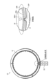
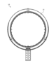
- FIG. 2 is a diagram showing the configuration of the housing for the radio wave control plate according to the present disclosure.
- the housing 10 for the radio wave control plate accommodates the first housing 20 inside the second housing 30 by sandwiching the first housing 20 between the second housing member 31 and the second housing member 32.
- FIG. 3 is a diagram showing the dimensions of the housing for the radio wave control plate according to the present disclosure.
- the diameter ⁇ 1 of the first housing 20 is smaller than the diameter ⁇ 2 of the second housing member 31 constituting the second housing 30.
- FIG. 4 is a diagram showing the position of the A-A cross section of the housing for the radio wave control plate according to the present disclosure, and the A-A cross section.
- the diagram shown on the left side of FIG. 4 is a diagram showing the position of the A-A cross section of the housing 10.
- the diagram shown on the right side of FIG. 4 is an A-A cross section of the housing 10 for the radio wave control plate according to the present disclosure.
- the first housing 20 is housed inside the second housing 30 including the second housing member 31 and the second housing member 32. Also, as shown in the diagram on the right side of FIG.
- the diameter ⁇ 1 of the first housing 20 is formed smaller than the diameter ⁇ 2 of the second housing member 31. Therefore, the second housing 30 can rotate inside the first housing 20 in the in-plane direction (X direction) shown in FIG. 4, in other words, in the direction along the plane horizontal to the radio wave control plate 1. This makes it possible to adjust the refraction angle in the direction horizontal to the plate surface of the radio wave control plate 1.
- FIG. 5 is a diagram showing the markings that serve as the scale for adjusting the angle in the in-plane direction of the housing 10 for a radio control plate according to the present disclosure, the positions of the protrusions that serve as markers, and details of the markings and protrusions. The diagram shown on the left side of FIG.
- FIG. 5 is a diagram showing the markings that serve as the scale for adjusting the angle in the in-plane direction of the housing 10 for a radio control plate, and the positions of the protrusions that serve as markers. As shown in the diagram on the left side of FIG. 5, the markings and protrusions are provided at the circled location near the base of the fixing portion 33.
- the diagram on the right side of FIG. 5 is a detailed view a of the area circled in the diagram on the left side of FIG. 5.
- a protrusion 31P is provided on the inner periphery of the second housing member 31.
- an engraving 20E is provided on the outer periphery of the first housing 20 as a marker for adjusting the angle in the in-plane direction.
- the engraving 20E may be, for example, a smaller engraving 20Es provided at a predetermined angular interval (e.g., 1 degree) and a larger engraving 20Eb provided at an angular interval larger than the angular interval (e.g., 10 degrees). Therefore, by using the engraving 20E as a scale and the protrusion 31P as a marker, it is possible to accurately adjust the angle in the in-plane direction (X direction) of the first housing 20 that houses the radio wave control plate 1 inside.
- FIG. 6 is a diagram showing the screw fastening points of the housing for the radio wave control plate according to the present disclosure.
- the first housing 20 and the second housing 30 are fastened together by inserting a screw into the screw hole at the circled location shown in FIG. 6 and turning the screw. This makes it possible to restrict the in-plane rotation of the first housing 20 inside the second housing 30. Therefore, it is possible to fix the in-plane angle of the radio wave control plate 1 stored inside the first housing 20.
- FIG. 7 is a diagram showing a structure for fastening the housing for the radio wave control plate and the metal plate according to the present disclosure.
- the housing 10 for the radio wave control plate according to the present disclosure is sandwiched and fixed between the first metal plate (combination of metal plates 4 and 5) and the metal plate (second metal plate) 6.
- the housing 10 for the radio wave control plate can rotate in the horizontal direction (Y direction) shown in FIG.
- the housing 10 is clamped and fixed between the first metal sheet (a combination of metal sheets 4 and 5) and the metal sheet (second metal sheet) 6, making it possible to adjust the horizontal angle (Y direction) of the radio wave control plate 1 and then fix the adjusted angle.
- FIG. 8 is a diagram showing the markings that serve as the scale for horizontal angle adjustment of the housing 10 for a radio control plate according to the present disclosure, the positions of the markings that serve as markers, and details of these markings.
- the diagram on the left side of FIG. 8 is a diagram showing the markings that serve as the scale for horizontal angle adjustment of the housing 10 for a radio control plate, and the positions of the markings that serve as markers. As shown in the diagram on the left side of FIG. 8, these markings are provided near the fastening portion between the housing 10 for a radio control plate and the metal plate 5.
- FIG. 8 The figure shown on the right side of FIG. 8 is a detailed view b of the vicinity of the fastening portion between the housing 10 for the radio wave control plate and the metal plate 5.
- an engraving 31E is provided near the fastening portion between the second housing member 31 and the metal plate 5, which serves as a mark for the horizontal rotation of the housing 10 for the radio wave control plate according to the present disclosure.
- an engraving 5E is provided on the upper surface of the metal plate 5, which serves as a scale for adjusting the angle of the horizontal rotation of the housing 10 for the radio wave control plate according to the present disclosure.
- the engraving 5E may include, for example, smaller engravings 5Es provided at predetermined angular intervals (e.g., 1 degree) and larger engravings 5Eb provided at angular intervals larger than the angular intervals (e.g., 10 degrees). Therefore, by using the engraving 5E as a scale and the engraving 31E as a mark, it is possible to accurately adjust the horizontal angle (Y direction) of the housing 10 that houses the radio wave control plate 1 inside.
- FIG. 9 is a diagram showing the fastening points of the housing for the radio wave control plate according to the present disclosure and the metal plate with screws.
- the first metal plate (combination of metal plates 4 and 5) and the metal plate (second metal plate) 6 are fastened together, and the housing 10 sandwiched between the first metal plate (combination of metal plates 4 and 5) and the metal plate (second metal plate) 6 is fixed.
- Fig. 10 is a side view of the housing for the radio wave control plate according to the present disclosure.
- the housing 10 for the radio wave control plate according to the present disclosure is fastened by a first metal plate (a combination of metal plates 4 and 5) and a metal plate (second metal plate) 6, and then a metal plate (third metal plate) 7 is connected to the metal plate (second metal plate) 6.
- FIG. 11 is a front view and a side view of the housing for the radio wave control plate according to the present disclosure.
- the metal plate (second metal plate) 6 fastened to the housing 10 for the radio wave control plate according to the present disclosure is fastened and fixed to the metal plate (third metal plate) 7 by inserting a screw into the screw hole at the circled location and turning the screw. Note that when the screw is loosened, the metal plate (second metal plate) 6 can rotate in the vertical direction (Z direction) shown in FIG.
- the vertical angle of the housing 10 for the radio wave control plate can be adjusted.
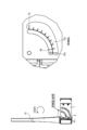
- FIG. 12 is a diagram showing the markings that serve as the scale for adjusting the vertical angle of the housing 10 for a radio control plate according to the present disclosure, the positions of the markings, and details of these markings.
- the diagram shown on the left side of FIG. 12 is a diagram showing the markings that serve as the scale for adjusting the vertical angle of the housing 10 for a radio control plate, and the positions of the markings that serve as markers. As shown in the diagram on the left side of FIG. 12, these markings are provided at the circled locations of the metal plate (second metal plate) 6 and the metal plate (third metal plate) 7 fastened to the housing 10 for a radio control plate.
- the figure on the right side of FIG. 12 is a detailed view c of the circled portion of the metal plate (second metal plate) 6 and the metal plate (third metal plate) 7 fastened to the housing 10 for the radio wave control plate.
- the side portion of the metal plate (second metal plate) 6 is provided with an engraving 6E that serves as a marker for the vertical rotation of the housing 10 for the radio wave control plate according to the present disclosure.
- the side portion of the metal plate (third metal plate) 7 is provided with an engraving 7E that serves as a scale for adjusting the angle of the vertical rotation of the housing 10 for the radio wave control plate according to the present disclosure.
- the engraving 7E may include, for example, smaller engravings 7Es provided at predetermined angular intervals (e.g., 1 degree) and larger engravings 7Eb provided at angular intervals larger than the angular intervals (e.g., 10 degrees). Therefore, by using the engraving 7E as a scale and the engraving 6E as a guide, it is possible to accurately adjust the vertical angle (Z direction) of the housing 10 that houses the radio wave control plate 1 inside.
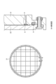
- FIG. 13 is a diagram showing the position where the air pressure adjustment sheet of the housing for the radio wave control plate according to the present disclosure is provided, and details of the air pressure adjustment sheet.
- the diagram shown on the left side of FIG. 13 is a diagram showing the position where the air pressure adjustment sheet S of the housing 10 for the radio wave control plate according to the present disclosure is provided.
- the air pressure adjustment sheet S of the housing 10 for the radio wave control plate according to the present disclosure is provided at the circled location on the outer periphery of the first housing member 21.
- the air pressure adjustment sheet S is a sheet that allows air to pass through but does not allow water to pass through.
- the diagram on the right side of Figure 13 is a detailed view d of the circled area on the outer periphery of the first housing member 21 where the air pressure adjustment sheet S of the housing 10 for the radio wave control plate according to the present disclosure is provided. As shown in the diagram on the right side of Figure 13, the air pressure adjustment sheet S of the housing 10 for the radio wave control plate according to the present disclosure is inserted into a hole H for the air pressure adjustment sheet provided on the outer periphery of the first housing member 21.
- FIG. 14 is a diagram showing the position of the B-B cross section of the first housing member according to the present disclosure, and the B-B cross section.
- the diagram shown on the left side of FIG. 14 is a diagram showing the position of the B-B cross section of the first housing member 21 according to the present disclosure.
- the B-B cross section of the first housing member 21 according to the present disclosure is a cross section taken perpendicular to the outer periphery of the first housing member 21.
- the diagram on the right side of FIG. 14 is a B-B cross-sectional view of the first housing member 21 according to the present disclosure.
- the air pressure adjustment sheet S according to the present disclosure is inserted into the hole H for the air pressure adjustment sheet in the first housing member 21 and is in contact with the first housing member 21.
- the air pressure inside the first housing 20 changes. Therefore, by providing the air pressure adjustment sheet S, when the air pressure inside the first housing 20 becomes high, the air pressure inside the first housing 20 is adjusted by letting high-pressure air out of the inside of the first housing 20 through the air pressure adjustment sheet S.
- the radio wave control device 100 of the present disclosure comprises a radio wave control plate 1 that reflects or refracts radio waves, a first housing 20 that houses the radio wave control plate 1 internally, and a second housing 30 that houses the first housing 20 internally, the first housing 20 and the second housing 30 forming a housing 10 for the radio wave control plate, and the first housing 20 is rotatable in an in-plane direction relative to the second housing 30.
- the first housing 20 of the radio wave control device 100 is engraved with markings that serve as scales for adjusting the angle of the first housing 20 in the in-plane direction, and the second housing 30 is provided with a protrusion that serves as a marker for adjusting the angle of the first housing 20 in the in-plane direction.
- the radio wave control device 100 further comprises a first metal plate (combination of metal plates 4 and 5) and a second metal plate 6 that sandwich and hold the second housing 30, and the second housing 30 is capable of adjusting its horizontal angle before being fastened and sandwiched between the first metal plate (combination of metal plates 4 and 5) and the second metal plate 6, and the first metal plate 4 is engraved with an engraving that serves as a marker for adjusting the horizontal angle of the second housing 30.
- the radio wave control device 100 further includes a third metal plate 7 that can be fastened to the second metal plate 6, and the second metal plate 6 can be adjusted in angle relative to the third metal plate 7 before being fastened to the third metal plate 7, and the third metal plate 7 is engraved with markings that serve as a scale for adjusting the angle of the second housing 30 in the vertical direction.
- the first housing 20 of the radio wave control device 100 comprises two first housing members 21, 22 and an air pressure adjustment sheet S that is provided between the two first housing members 21, 22 and adjusts the air pressure inside the first housing 20, and one of the two first housing members has a hole H for the air pressure adjustment sheet S.
- This configuration makes it possible to reduce deformation of the housing 10 due to changes in air pressure inside the housing 10, even if a temperature change occurs in the housing 10.
- the housing 10 for the radio wave control plate comprises a first housing 20 that houses the radio wave control plate 1 therein, and a second housing 30 that houses the first housing 20 therein, and the first housing 20 is rotatable in-plane relative to the second housing 30.
- the radio wave control device can be used, for example, as a radio wave control device in which the angle of the radio wave control plate can be easily adjusted.
- the housing for the radio wave control plate according to this embodiment can be used, for example, as a housing for the radio wave control plate in which the angle of the radio wave control plate can be easily adjusted.
- Radio wave control device 100 Radio wave control device 1 Radio wave control plate 10 Housing 20 First housing 21 First housing member 22 First housing member 30 Second housing 31 Second housing member 32 Second housing member 33 Fixing part 4 Metal plate (one part of the first metal plate) 5. Sheet metal (part of the first sheet metal) 6. Sheet metal (second sheet metal) 7. Sheet metal (third sheet metal) 8 Sheet metal 9 Gasket
Landscapes
- Physics & Mathematics (AREA)
- Electromagnetism (AREA)
- Shielding Devices Or Components To Electric Or Magnetic Fields (AREA)
Priority Applications (1)
| Application Number | Priority Date | Filing Date | Title |
|---|---|---|---|
| JP2025527870A JPWO2024257674A1 (https=) | 2023-06-12 | 2024-06-05 |
Applications Claiming Priority (2)
| Application Number | Priority Date | Filing Date | Title |
|---|---|---|---|
| JP2023-096281 | 2023-06-12 | ||
| JP2023096281 | 2023-06-12 |
Publications (1)
| Publication Number | Publication Date |
|---|---|
| WO2024257674A1 true WO2024257674A1 (ja) | 2024-12-19 |
Family
ID=93851934
Family Applications (1)
| Application Number | Title | Priority Date | Filing Date |
|---|---|---|---|
| PCT/JP2024/020591 Ceased WO2024257674A1 (ja) | 2023-06-12 | 2024-06-05 | 電波制御装置、及び電波制御板用の筐体 |
Country Status (2)
| Country | Link |
|---|---|
| JP (1) | JPWO2024257674A1 (https=) |
| WO (1) | WO2024257674A1 (https=) |
Citations (2)
| Publication number | Priority date | Publication date | Assignee | Title |
|---|---|---|---|---|
| WO2022091986A1 (ja) * | 2020-10-30 | 2022-05-05 | 京セラ株式会社 | 通信システム、通信方法、および電波屈折板の設置方法 |
| WO2022259565A1 (ja) * | 2021-06-11 | 2022-12-15 | 日本電業工作株式会社 | 電波散乱装置及び電波散乱部材 |
-
2024
- 2024-06-05 WO PCT/JP2024/020591 patent/WO2024257674A1/ja not_active Ceased
- 2024-06-05 JP JP2025527870A patent/JPWO2024257674A1/ja active Pending
Patent Citations (2)
| Publication number | Priority date | Publication date | Assignee | Title |
|---|---|---|---|---|
| WO2022091986A1 (ja) * | 2020-10-30 | 2022-05-05 | 京セラ株式会社 | 通信システム、通信方法、および電波屈折板の設置方法 |
| WO2022259565A1 (ja) * | 2021-06-11 | 2022-12-15 | 日本電業工作株式会社 | 電波散乱装置及び電波散乱部材 |
Also Published As
| Publication number | Publication date |
|---|---|
| JPWO2024257674A1 (https=) | 2024-12-19 |
Similar Documents
| Publication | Publication Date | Title |
|---|---|---|
| CN1615562B (zh) | 用于改进近程范围无线网络性能的天线系统 | |
| EP2919322B1 (en) | Reflective array surface and reflective array antenna | |
| US10312588B2 (en) | Phased-array antenna and multi-face array antenna device | |
| US12562496B2 (en) | Meta-structure based reflectarrays for enhanced wireless applications | |
| US9972916B2 (en) | Planar array antenna with changeable beam angle | |
| US20090002261A1 (en) | Alignment Unit for Directional Radios, In Particular Directional Radio Antennas | |
| US12052834B2 (en) | Attaching device for flexible display panel | |
| US10571684B2 (en) | Micro-mirror array having pillars which form portions of electrical paths between mirror electrodes and mirrors | |
| JP2006329970A (ja) | 回転可能なフォーカスビューを備えた動作検出デバイス、及び特定のフォーカスビューを選択する方法 | |
| WO2024257674A1 (ja) | 電波制御装置、及び電波制御板用の筐体 | |
| EP4177707A3 (en) | Display device | |
| JP5230359B2 (ja) | アンテナ装置 | |
| US20080273136A1 (en) | Positioning Structure For Sheet-Shaped Component And Display Device Using Same | |
| CN114439172A (zh) | 一种装配式墙板调平安装结构 | |
| EP2319050B1 (en) | Neutron guide system comprising neutron guide sections, support for neutron guide sections and method of aligning neutron guide sections | |
| CN113433789B (zh) | 一种立体放映装置 | |
| CN101803365B (zh) | 摄像装置 | |
| EP0739051B1 (en) | A layered antenna | |
| CN116845579A (zh) | 一种基于双超表面的折叠反射阵列天线 | |
| CN220527189U (zh) | 一种天线装置及基站 | |
| JP5174645B2 (ja) | 開口部装置 | |
| JP2006311421A (ja) | 偏波変換器及びそれを用いたアンテナ装置 | |
| CN118399055B (zh) | 角度可调节的ris相控阵设备塔上固定装置及其安装方法 | |
| JPH0210651Y2 (https=) | ||
| JP2002038618A (ja) | 外壁の断熱構造 |
Legal Events
| Date | Code | Title | Description |
|---|---|---|---|
| 121 | Ep: the epo has been informed by wipo that ep was designated in this application |
Ref document number: 24823292 Country of ref document: EP Kind code of ref document: A1 |
|
| ENP | Entry into the national phase |
Ref document number: 2025527870 Country of ref document: JP Kind code of ref document: A |
|
| WWE | Wipo information: entry into national phase |
Ref document number: 2025527870 Country of ref document: JP |
|
| NENP | Non-entry into the national phase |
Ref country code: DE |