WO2024257618A1 - 操作装置 - Google Patents
操作装置 Download PDFInfo
- Publication number
- WO2024257618A1 WO2024257618A1 PCT/JP2024/019847 JP2024019847W WO2024257618A1 WO 2024257618 A1 WO2024257618 A1 WO 2024257618A1 JP 2024019847 W JP2024019847 W JP 2024019847W WO 2024257618 A1 WO2024257618 A1 WO 2024257618A1
- Authority
- WO
- WIPO (PCT)
- Prior art keywords
- display area
- operation unit
- display
- gaze
- unit
- Prior art date
- Legal status (The legal status is an assumption and is not a legal conclusion. Google has not performed a legal analysis and makes no representation as to the accuracy of the status listed.)
- Ceased
Links
Images









Classifications
-
- B—PERFORMING OPERATIONS; TRANSPORTING
- B60—VEHICLES IN GENERAL
- B60K—ARRANGEMENT OR MOUNTING OF PROPULSION UNITS OR OF TRANSMISSIONS IN VEHICLES; ARRANGEMENT OR MOUNTING OF PLURAL DIVERSE PRIME-MOVERS IN VEHICLES; AUXILIARY DRIVES FOR VEHICLES; INSTRUMENTATION OR DASHBOARDS FOR VEHICLES; ARRANGEMENTS IN CONNECTION WITH COOLING, AIR INTAKE, GAS EXHAUST OR FUEL SUPPLY OF PROPULSION UNITS IN VEHICLES
- B60K35/00—Instruments specially adapted for vehicles; Arrangement of instruments in or on vehicles
-
- B—PERFORMING OPERATIONS; TRANSPORTING
- B60—VEHICLES IN GENERAL
- B60R—VEHICLES, VEHICLE FITTINGS, OR VEHICLE PARTS, NOT OTHERWISE PROVIDED FOR
- B60R16/00—Electric or fluid circuits specially adapted for vehicles and not otherwise provided for; Arrangement of elements of electric or fluid circuits specially adapted for vehicles and not otherwise provided for
- B60R16/02—Electric or fluid circuits specially adapted for vehicles and not otherwise provided for; Arrangement of elements of electric or fluid circuits specially adapted for vehicles and not otherwise provided for electric constitutive elements
- B60R16/023—Electric or fluid circuits specially adapted for vehicles and not otherwise provided for; Arrangement of elements of electric or fluid circuits specially adapted for vehicles and not otherwise provided for electric constitutive elements for transmission of signals between vehicle parts or subsystems
- B60R16/027—Electric or fluid circuits specially adapted for vehicles and not otherwise provided for; Arrangement of elements of electric or fluid circuits specially adapted for vehicles and not otherwise provided for electric constitutive elements for transmission of signals between vehicle parts or subsystems between relatively movable parts of the vehicle, e.g. between steering wheel and column
-
- G—PHYSICS
- G06—COMPUTING OR CALCULATING; COUNTING
- G06F—ELECTRIC DIGITAL DATA PROCESSING
- G06F3/00—Input arrangements for transferring data to be processed into a form capable of being handled by the computer; Output arrangements for transferring data from processing unit to output unit, e.g. interface arrangements
- G06F3/01—Input arrangements or combined input and output arrangements for interaction between user and computer
-
- G—PHYSICS
- G06—COMPUTING OR CALCULATING; COUNTING
- G06F—ELECTRIC DIGITAL DATA PROCESSING
- G06F3/00—Input arrangements for transferring data to be processed into a form capable of being handled by the computer; Output arrangements for transferring data from processing unit to output unit, e.g. interface arrangements
- G06F3/01—Input arrangements or combined input and output arrangements for interaction between user and computer
- G06F3/03—Arrangements for converting the position or the displacement of a member into a coded form
- G06F3/033—Pointing devices displaced or positioned by the user, e.g. mice, trackballs, pens or joysticks; Accessories therefor
- G06F3/038—Control and interface arrangements therefor, e.g. drivers or device-embedded control circuitry
-
- G—PHYSICS
- G06—COMPUTING OR CALCULATING; COUNTING
- G06F—ELECTRIC DIGITAL DATA PROCESSING
- G06F3/00—Input arrangements for transferring data to be processed into a form capable of being handled by the computer; Output arrangements for transferring data from processing unit to output unit, e.g. interface arrangements
- G06F3/01—Input arrangements or combined input and output arrangements for interaction between user and computer
- G06F3/048—Interaction techniques based on graphical user interfaces [GUI]
- G06F3/0481—Interaction techniques based on graphical user interfaces [GUI] based on specific properties of the displayed interaction object or a metaphor-based environment, e.g. interaction with desktop elements like windows or icons, or assisted by a cursor's changing behaviour or appearance
- G06F3/04812—Interaction techniques based on cursor appearance or behaviour, e.g. being affected by the presence of displayed objects
-
- G—PHYSICS
- G09—EDUCATION; CRYPTOGRAPHY; DISPLAY; ADVERTISING; SEALS
- G09G—ARRANGEMENTS OR CIRCUITS FOR CONTROL OF INDICATING DEVICES USING STATIC MEANS TO PRESENT VARIABLE INFORMATION
- G09G5/00—Control arrangements or circuits for visual indicators common to cathode-ray tube indicators and other visual indicators
-
- G—PHYSICS
- G09—EDUCATION; CRYPTOGRAPHY; DISPLAY; ADVERTISING; SEALS
- G09G—ARRANGEMENTS OR CIRCUITS FOR CONTROL OF INDICATING DEVICES USING STATIC MEANS TO PRESENT VARIABLE INFORMATION
- G09G5/00—Control arrangements or circuits for visual indicators common to cathode-ray tube indicators and other visual indicators
- G09G5/36—Control arrangements or circuits for visual indicators common to cathode-ray tube indicators and other visual indicators characterised by the display of a graphic pattern, e.g. using an all-points-addressable [APA] memory
- G09G5/37—Details of the operation on graphic patterns
Definitions
- the present invention relates to an operating device.
- the display control unit of this display device can enlarge the display mode of the displayed symbol in response to the user's line of sight.
- This symbol is an operation icon for operating the display device.
- the sum of the multiple display areas is larger than each individual display area.
- the sum of the multiple display areas is large, so the operability of the icon does not necessarily improve.
- the object of the present invention is to provide an operating device that can improve operability.
- the operating device is disposed in a vehicle and includes an operating unit that receives a first operation, a gaze detection unit that detects the gaze of a vehicle occupant, and a control unit that, when the operating unit receives the first operation and determines, among a plurality of display areas that display images, the existence of a gaze position display area in which the occupant's gaze is located, allows only operation of the gaze position display area via the operating unit.
- FIG. 1A is an explanatory diagram showing a vehicle in which an operating device according to an embodiment is arranged.
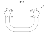
- FIG. 1B is an explanatory diagram showing a steering wheel on which an operating device according to an embodiment is arranged.
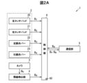
- FIG. 2A is a block diagram of an operating device according to an embodiment.
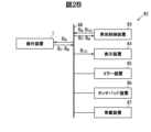
- FIG. 2B is a block diagram of a vehicle control system including the operation device according to the embodiment.
- FIG. 3A is a diagram for explaining gaze detection by a gaze detection unit of the operating device according to the embodiment.
- FIG. 3B is an explanatory diagram showing the display device.
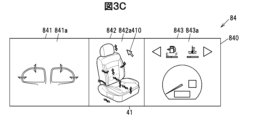
- FIG. 3C is an explanatory diagram showing a display device.
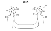
- FIG. 4A is a diagram for explaining a first operation in the operating device according to the embodiment.
- FIG. 4A is a diagram for explaining a first operation in the operating device according to the embodiment.
- FIG. 4B is an explanatory diagram showing a display area in which a line of sight is detected.
- FIG. 4C is an explanatory diagram showing the gaze position display area.
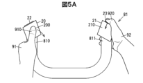
- FIG. 5A is an explanatory diagram showing an operation for changing a layout.
- FIG. 5B is an explanatory diagram showing a display area in which a line of sight is detected.
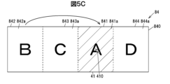
- FIG. 5C is an explanatory diagram showing a change in layout.
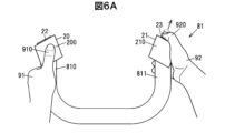
- FIG. 6A is an explanatory diagram showing an operation for switching the display areas.
- FIG. 6B is an explanatory diagram showing a display area in which a line of sight is detected.
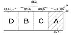
- FIG. 6C is an explanatory diagram showing switching of the display areas.
- FIG. 7 is a flow chart showing the operation of making a desired display area operable.
- FIG. 8 is a flowchart showing the operation of changing the layout of the display area.
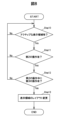
- FIG. 9 is a flowchart showing the operation of switching the display areas.
- the operating device of the embodiment is disposed in a vehicle and has an operating unit that accepts a first operation, a gaze detection unit that detects the gaze of a vehicle occupant, and a control unit that, when the operating unit accepts the first operation and determines, among a plurality of display areas that display images, the existence of a gaze position display area in which the occupant's gaze is located, allows only operation on the gaze position display area via the operating unit.
- This operating device allows only the operation of the gaze position display area where the occupant directs his or her gaze among the multiple display areas, so compared to when the entirety of the multiple display areas is the target of operation, the area that can be operated is limited, improving operability.
- FIG. 1A is an explanatory diagram showing a vehicle in which an operating device according to an embodiment is arranged
- Fig. 1B is an explanatory diagram showing a steering wheel in which an operating device according to an embodiment is arranged.
- Fig. 2A is a block diagram of an operating device according to an embodiment
- Fig. 2B is a block diagram of a vehicle control system including the operating device.
- Fig. 3A is a diagram for explaining gaze detection by a gaze detection unit of an operating device according to an embodiment
- Figs. 3B and 3C are diagrams showing a display device.
- the operation device 1 is disposed in a vehicle 8 and includes an operation unit 2 that receives a first operation, a gaze detection unit 4 that detects the gaze 40 of an occupant 9 of the vehicle 8, and a control unit 6 that allows only operation of the gaze position display area 41 via the operation unit 2 when the operation unit 2 receives the first operation and, among multiple display areas that display images, it is determined that there is a gaze position display area 41 in which the gaze 40 of the occupant 9 is located.
- the control unit 6 is configured to allow only operation via the operation unit 2 on the gaze position display area 41, and to display a pointer 410 that can be operated via the operation unit 2 in the gaze position display area 41.
- the operation unit 2 also has a left operation unit and a right operation unit arranged on the left and right sides of the steering wheel 81 of the vehicle 8.
- the control unit 6 defines an operation performed on the left operation unit and the right operation unit, which overlaps for at least a partial period, as a first operation. This operation which overlaps for at least a partial period indicates that the period of the operation performed on the left operation unit and the period of the operation performed on the right operation unit overlap for at least a partial period.
- the operation unit 2 has a left operation unit and a right operation unit which are touchpads that accept touch operations.
- the left operation unit is referred to as the left touchpad 20
- the right operation unit is referred to as the right touchpad 21.
- the left operation unit and the right operation unit are not limited to touchpads, and may be a joystick or a cross key with a push button located in the center.
- the control unit 6 When the control unit 6 receives touch operations performed on the left touchpad 20 and the right touchpad 21, which overlap for at least a portion of the time, and determines the presence of the gaze position display area 41, it allows only operations on the gaze position display area 41.
- the first operation is a touch operation performed on the left touchpad 20 and the right touchpad 21, which overlap for at least a portion of the time.
- this touch operation indicates a contact of a left operating finger 910 of a left hand 91 with the operating surface 200 of the left touchpad 20, and a contact of a right operating finger 920 of a right hand 92 with the operating surface 210 of the right touchpad 21.
- the left operating finger 910 and the right operating finger 920 are thumbs as an example, but are not limited to this, and one may be a thumb and the other another finger, or both may be fingers other than thumbs.
- the operation unit 2 further accepts a second operation.
- the control unit 6 is configured to move the gaze position display area 41 to change the layout of the multiple display areas when a second operation is performed on the operation unit 2 after only allowing operations on the gaze position display area 41, and then a third operation is performed.
- the operation unit 2 has a left touchpad 20 and a right touchpad 21 arranged on the left and right sides of the steering wheel 81 of the vehicle 8, and a specific operation unit that is provided adjacent to at least one of the left touchpad 20 and the right touchpad 21 and that accepts a second operation.
- the specific operation unit in this embodiment is a left operation bar 22 arranged adjacent to the left touch pad 20, and a right operation bar 23 arranged adjacent to the right touch pad 21.
- the left operation bar 22 and the right operation bar 23 are push switches, but are not limited to this, and may be capacitive touch sensors.
- the second operation is, for example, a long press operation performed on at least one of the left operation bar 22 and the right operation bar 23, but is not limited to this, and may be a long press operation, a touch operation, a tap operation, etc., performed at a specific position on at least one of the left touchpad 20 and the right touchpad 21.
- the third operation is, for example, a drag-and-drop operation performed on one of the left touchpad 20 and the right touchpad 21, or an operation including a selection operation of a destination display area by changing the line of sight of the occupant 9 and a release of the second operation, but is not limited thereto, and may be a flick operation or a tracing operation performed on one of the left touchpad 20 and the right touchpad 21.
- the desired display area may be moved to a position corresponding to the end position of the operation, or the position of the desired display area may be changed by repeating a flick operation or a tracing operation multiple times until the second operation is released, and releasing the second operation.
- the third operation in this embodiment is, for example, an operation that enables a layout change by a drag-and-drop operation and a layout change by moving the line of sight.
- the occupant 9 can activate the desired display area by performing touch operations on the left touchpad 20 and the right touchpad 21 and directing the line of sight 40 to the display area that he or she wants to operate, that is, by selecting the desired display area and making it operable.
- the occupant 9 is, for example, a driver seated in the driver's seat 800, but is not limited thereto, and may be an occupant seated in the passenger seat 801.
- the occupant 9 seated in the passenger seat 801 can, for example, perform a first operation on the touch pad device 86 arranged on the floor console 802 and direct the line of sight 40 to the desired display area, thereby making only the desired display area operable.
- the occupant 9 seated in the passenger seat 801 can also change the layout of the above-mentioned multiple display areas or swap the display positions by combining the operation with a switch arranged near the touch pad device 86.
- the vehicle 8 is provided with a display device 84 having a large display screen 840 that extends from the front of the driver's seat 800 to the front of the passenger seat 801.
- this display screen 840 is large enough to cover most of the left and right sides of the instrument panel 803.
- the operation surface 200 of the left touch pad 20 and the operation surface 210 of the right touch pad 21 are much smaller than the large display screen 840. It is difficult for the occupant 9 to operate the entire display screen 840 by operating the operation surface 200 and the operation surface 210.
- the operation device 1 of this embodiment is configured to reduce the difficulty caused by the difference in ratio by allowing operation on a display area basis, rather than the entire display screen 840.
- the display area is an area obtained by dividing the display screen 840 in the vertical direction, but is not limited to this, and may be shaped so that at least a portion of the display area overlaps in the vertical direction.
- the operation device 1 constitutes a vehicle control system 82 together with a display device 84, as shown in FIG. 2B.
- this vehicle control system 82 is configured to include a vehicle control device 83, a display device 84, a mirror device 85, a touchpad device 86, an in-vehicle device 87, and a vehicle LAN 88 (Local Area Network).
- the vehicle control device 83 is a microcomputer that provides overall control of the vehicle 8, and is configured to control the drive device, automatic driving control, driving assistance control, etc. As an example, the vehicle control device 83 controls the display device 84.
- the display device 84 is, for example, an organic EL (Electro-Luminescence) display, a mini LED (Light Emitting Diode), or a micro LED display.
- the display device 84 has, for example, a display screen 840 that is long in the left-right direction of the vehicle 8.
- the display screen 840 is divided into a plurality of display areas.
- the multiple display areas may be configured from multiple displays.
- the display device 84 may be configured from multiple displays.
- the display device 84 may be configured as a head-up display that projects an image onto the windshield 804, or may be configured to include a head-up display.
- Figure 3B shows an example of a display screen 840 divided into four display areas, a first display area 841 to a fourth display area 844.
- the first display area 841 to the fourth display area 844 may have the same shape or may have different shapes.
- the first display area 841 displays, as an example, a display image 841a relating to multiple functions of an air conditioner.
- the second display area 842 displays, as an example, a display image 842a relating to a map image of a navigation device.
- the third display area 843 displays, as an example, a display image 843a relating to speed, direction indication, etc.
- the fourth display area 844 displays, as an example, a display image 844a relating to a fuel gauge, water temperature gauge, etc.
- Figure 3C shows an example in which the display screen 840 is divided into three display areas: a first display area 841 to a third display area 843.
- a display image 841a relating to the adjustment function of the mirror device 85 is displayed.
- a display image 842a relating to the seat device is displayed.
- a display image 843a relating to speed, direction indication, etc. is displayed.
- control unit 6 is configured to keep at least the display area that displays the speed of the vehicle 8, among the multiple display areas, in front of the occupant 9, and to restrict changes to the layout of this display area and changes to the display position of this display area.
- the third display area 843 in FIG. 3B and the third display area 843 in FIG. 3C are display areas that display the speed. As an example, this display area that displays the speed is legally required to be displayed in front where it is easily visible to the driver. Therefore, the control unit 6 is configured to maintain the display position of the display area that displays the speed, and not to change the layout including this display area or change its display position.
- the mirror device 85 is for checking the rear of the vehicle 8, and may be a physical mirror or an electronic mirror.
- the mirror device 85 is a physical mirror, it is configured so that the angle of the mirror portion can be changed, as shown in the first display area 841 of FIG. 3C.
- the mirror device 85 is an electronic mirror, it is configured so that it is equipped with a camera and is configured to display in the display area the image of the rear view, such as enlarging or reducing the image, adjusting the brightness, and displaying a warning of the approach of other vehicles.
- the display device 84 displays images of the left and right rear views in display areas located at the left and right ends.
- the touchpad device 86 is disposed on the floor console 802 between the driver's seat 800 and the passenger seat 801.
- This touchpad device 86 is a capacitive touchpad, similar to the left touchpad 20 and the right touchpad 21, and is configured to detect touch operations, etc.
- Examples of the in-vehicle devices 87 include an air conditioning device that adjusts the temperature inside the vehicle, a navigation device that displays a map of the current location and provides guidance to the destination, a seat device that controls the position and inclination of the seat, and a music and video playback device that plays music and videos.
- the display device 84 is configured to display information related to these in-vehicle devices 87 as well as images to which adjustments, functions on/off, etc. are assigned.
- This vehicle control system 82 is connected to an operating device 1, a vehicle control device 83, a display device 84, and the like via a vehicle LAN 88.
- This vehicle LAN 88 is, for example, a vehicle network such as a CAN (Controller Area Network) or a LIN (Local Interconnect Network) that enables the mutual exchange of signals, information, and the like by wire and wirelessly.
- CAN Controller Area Network
- LIN Local Interconnect Network
- the operation unit 2 is configured with a left touchpad 20, a right touchpad 21, a left operation bar 22, and a right operation bar 23.
- the left touchpad 20 and the right touchpad 21 are, for example, capacitive touchpads, but are not limited to this and may be pressure-sensitive touchpads, etc.
- the left touchpad 20 and the right touchpad 21 are capable of, for example, touch operations, tap operations, double tap operations, tracing operations, drag-and-drop operations, flick operations, pinch out (pinch open) operations, and pinch in (pinch close) operations. These operations may be performed on the left touchpad 20 and the right touchpad 21 separately, or may be performed separately.
- the touch operation here refers to an operation of continuous contact or pressing and holding the operation surface, rather than an operation of momentarily touching the operation surface.
- the steering wheel 81 on which the operation unit 2 is arranged is an irregular steering wheel that has no top and makes the display device 84 easier to see, as shown in FIG. 1A.
- the left touchpad 20 is arranged on the tip side of the left grip portion 810 of the steering wheel 81.
- the right touchpad 21 is arranged on the tip side of the right grip portion 811.
- the operation surface 200 of the left touchpad 20 and the operation surface 210 of the right touchpad 21 each have a rectangular shape with one corner facing upward.
- the left operation bar 22 is arranged along the upper edge of the operation surface 200 of the left touchpad 20.
- the right operation bar 23 is arranged along the upper edge of the operation surface 210 of the right touchpad 21.
- the left touchpad 20 and the right touchpad 21 output left touchpad operation information S1 and right touchpad operation information S2, which are information relating to the performed operation, to the control unit 6.
- the left operation bar 22 and the right operation bar 23 output left operation information S3 and right operation information S4 to the control unit 6 based on the performed push operation or long press operation.
- the gaze detection unit 4 is electrically connected to the camera 3.
- the camera 3 is disposed so that a face 90 of an occupant 9 seated in a driver's seat 800 falls within an imaging range 30.
- the camera 3 is disposed on an instrument panel 803 in front of the occupant 9.
- the camera 3 captures an image of the imaging range 30 using infrared rays and outputs image information S5, which is information on the captured image, to the gaze detection unit 4.
- the camera 3 may be disposed as an in-vehicle device 87 and connected to the gaze detection unit 4 via a vehicle LAN 88.
- the gaze detection unit 4 detects the gaze 40 of the occupant 9 based on the image information S5 acquired from the camera 3.
- One example of a method for detecting the gaze 40 is a method for detecting the gaze 40 from the positional relationship between a stationary part (reference point) and a moving part (moving point) of the eye of the occupant 9, but is not limited to this.
- the gaze detection unit 4 outputs gaze information S6, which is information on the coordinates of the gaze 40 in a coordinate system set on the display screen 840, to the control unit 6. That is, the gaze detection unit 4 calculates the coordinates where the gaze 40 intersects with the display screen 840, and outputs it as the gaze information S6 .
- the communication unit 5 is configured to exchange information and signals between the operation device 1, the vehicle control device 83, the display device 84, and the like via the vehicle LAN 88.
- the control unit 6 is a microcomputer including a CPU (Central Processing Unit) that performs calculations and processing on acquired data according to a stored program, a RAM (Random Access Memory) that is a semiconductor memory, and a ROM (Read Only Memory).
- the ROM stores, for example, a program for the control unit 6 to operate.
- the RAM is used, for example, as a storage area for temporarily storing calculation results.
- the control unit 6 also has a means for generating a clock signal therein and operates based on this clock signal.
- the control unit 6 has operation pattern information 60 as shown in FIG. 2A.
- This operation pattern information 60 includes information on an operation pattern that enables a desired display area to be operated, information on an operation pattern for changing the layout of the gaze position display area 41, and information on an operation pattern for switching the display area.
- the operation pattern can be set by the occupant 9, as an example. That is, as described later, when changing the layout, the occupant 9 may be determined to perform a long press on the right operation bar 23 but also a long press on the left operation bar 22.
- the control unit 6 acquires display area information S9 related to the display area from the vehicle control device 83.
- the display area information S9 is not limited to the vehicle control device 83, and if there is a control device other than the vehicle control device 83 that controls the display device 84, the display area information S9 may be acquired from this control device.
- the display area information S9 is, for example, information specifying the range of the display area for the display screen 840.
- the control unit 6 determines in which display area the line of sight 40 is located, that is, the line of sight position display area 41, based on the line of sight information S6 acquired from the line of sight detection unit 4 and the display area information S9 acquired from the vehicle control device 83.
- the control unit 6 outputs display instruction information S7 related to the gaze position display area 41 to the vehicle control device 83 via the vehicle LAN 88.
- the control unit 6 also generates operation unit operation information S8 based on an operation performed on the operation unit 2, and outputs the information to the vehicle control device 83 via the vehicle LAN 88.
- the display instruction information S7 includes information related to a change in the layout of the display area, and information related to switching the display position of the display area.
- the control unit 6 may also be configured to transmit the operation unit operation information S8 to an in-vehicle device 87 corresponding to the gaze position display area 41.
- the vehicle control device 83 outputs display control information S10 for controlling the display of the display device 84 based on the acquired display instruction information S7 .
- This display control information S10 includes at least information on an image related to the in-vehicle device 87 to be displayed on the display device 84, and information on in which display area the image is to be displayed.
- the vehicle control device 83 acquires information relating to the display images 841a to 844a from the related in-vehicle device 87 or the like and displays them on the display screen 840.
- the vehicle control device 83 acquires the operation unit operation information S8 from the operation device 1, the vehicle control device 83 moves the pointer 410 displayed in the operable display area, scrolls the menu, or the like.
- the vehicle control device 83 acquires the display instruction information S7 , it activates the gaze position display area 41, changes the layout, or switches the display position.
- FIG. 4A is a diagram for explaining an example of a first operation of the operating device according to the embodiment
- Figure 4B is a diagram showing an example of a display area where a gaze is detected
- Figure 4C is a diagram showing an example of an eye gaze position display area that has become operable.
- a third display area 843 that displays a display image 843a of "C”
- a fourth display area 844 that displays a display image 844a of "D" are displayed on a display screen 840 as a plurality of display areas.
- the eye gaze position display area 41 that has become operable is indicated by diagonal lines.
- FIGs 5A to 5C and Figures 6A to 6C described later display areas and display images are illustrated based on Figures 4A to 4C.
- FIG. 4B shows the case where the line of sight 40 is directed to the second display area 842.
- the desired display area of the occupant 9 is the second display area 842.
- this first operation is an operation of pressing and holding the operation surface 200 of the left touchpad 20 with the left operating finger 910 of the left hand 91 and pressing and holding the operation surface 210 of the right touchpad 21 with the right operating finger 920 of the right hand 92, with the periods of pressing and holding at least partially overlapping.
- control unit 6 determines that a first operation has been performed based on the left touchpad operation information S1 output from the left touchpad 20, the right touchpad operation information S2 output from the right touchpad 21, and the operation pattern information 60, it controls the gaze detection unit 4 to check the gaze 40.
- control unit 6 may be configured to check the operation after determining that the gaze 40 is located on the display screen 840.
- the control unit 6 When the control unit 6 detects the line of sight 40 in any one of the display areas while the long press operation on the left touchpad 20 and the right touchpad 21 continues, the control unit 6 outputs display instruction information S7 for designating the display area in which the line of sight 40 is detected as the line of sight position display area 41.
- the control unit 6 since the display area in which the line of sight 40 is detected is the second display area 842, the control unit 6 outputs display instruction information S7 for displaying the pointer 410 in the second display area 842, which is the line of sight position display area 41 and is the desired display area of the occupant 9.
- the occupant 9 When the occupant 9 wishes to operate a display area other than the second display area 842, the occupant 9 performs a long press operation on the left touchpad 20 and the right touchpad 21, and moves the line of sight 40 to the desired display area to move the pointer 410 and enable operation.
- FIG. 5A is a diagram showing an example of an operation for changing the layout by an operating device according to an embodiment
- FIG. 5B is a diagram showing an example of a display area where a line of sight is detected
- FIG. 5C is a diagram showing an example of a change in the layout.
- the occupant 9 When changing the layout of a desired display area, the occupant 9 first performs a first operation to make the display area to be changed operable, and then directs the line of sight 40 to the desired display area.
- Figure 5B shows the case where the line of sight 40 is directed to the first display area 841. Note that if the display area to be changed is already active, it is not necessary to perform the first operation.
- the occupant 9 performs a long press operation on the right operation bar 23 as a second operation, and a drag-and-drop operation on the operation surface 200 of the left touchpad 20 as a third operation, as shown in FIG. 5A.
- the occupant 9 may also perform a drag-and-drop operation on the operation surface 210 of the right touchpad 21 while performing a long press operation on the left operation bar 22.
- the occupant 9 When the occupant 9 wishes to display the first display area 841 at the position of the third display area 843, the occupant 9 performs a drag operation from left to right on the operation surface 200 as shown in FIG. 5C, and when the first display area 841 reaches the desired position, a drop operation is performed, i.e., the left operation finger 910 is released from the operation surface 200.
- the control unit 6 determines that a drag-and-drop operation is being performed on the first display area 841 based on right operation information S4 output from the right operation bar 23 when the second operation is performed, left touchpad operation information S1 output from the left touchpad 20 when the third operation is performed, and operation pattern information 60.
- the control unit 6 outputs display instruction information S7 indicating to change the layout of the first display area 841 to the fourth display area 844 while keeping the first display area 841 active.
- FIG. 6A is a diagram showing an example of an operation of switching display areas performed on an operating device according to an embodiment
- FIG. 6B is a diagram showing an example of a display area in which a line of sight is detected
- FIG. 6C is a diagram showing an example of switching display areas.
- the occupant 9 When swapping the display position of a desired display area, the occupant 9 first performs a first operation to set the display area to be swapped as the gaze position display area 41, and then directs the gaze 40 to the desired display area.
- Figure 6B shows a case where the first display area 841 has been set as the gaze position display area 41. Note that if the desired display area is already active, it is not necessary to perform the first operation.
- FIG. 6A the occupant 9 performs a long press on the right operation bar 23 as a second operation, and sends the line of sight 40 to the display area that is to be replaced with the line of sight position display area 41.
- FIG. 6B shows the case where the line of sight 40 is sent to the fourth display area 844.
- the occupant 9 can switch the display areas by performing a long press on the right operation bar 23 as a second operation, sending the line of sight 40 to the fourth display area 844, and then releasing the right operation finger 920 from the right operation bar 23.
- the third operation is an operation that includes an operation of sending the line of sight 40 to the fourth display area 844 and an operation of releasing the right operation finger 920 from the right operation bar 23.
- the occupant 9 may also perform a long press on the left operation bar 22 and send the line of sight 40 while performing the long press operation.
- the control unit 6 determines that the long press operation of the right operation bar 23 has been released for swapping based on the gaze information S6 output from the gaze detection unit 4 , the right operation information S4 output from the right operation bar 23, and the operation pattern information 60.
- the control unit 6 outputs display instruction information S7 indicating to swap the display positions of the first display area 841 and the fourth display area 844 with the first display area 841 being active.
- the control unit 6 of the operation device 1 for enabling operation of a desired display area monitors whether a first operation is performed on the operation unit 2.
- Step 1 When “Yes” in Step 1 is established, that is, when a touch operation in which at least a part of a period of time overlaps on the left touchpad 20 and the right touchpad 21, that is, a first operation, is detected (Step 1: Yes), the control unit 6 controls the gaze detection unit 4 to start detecting the gaze 40 of the occupant 9 (Step 2).
- the control unit 6 When the touch operation on the left touchpad 20 and the right touchpad 21, i.e., the first operation, continues and a line of sight 40 is detected in any of the multiple display areas (Step 3: Yes), the control unit 6 outputs display instruction information S7 that activates the display area in which the detected line of sight 40 is located, i.e., makes it operable (Step 4).
- step 3 if the first operation continues and the line of sight 40 is not detected in any of the multiple display areas (Step 3: No), the control unit 6 proceeds to step 1.
- the operation control unit 6 for changing the layout of the display area outputs display instruction information S7 for changing the layout of the display area when “Yes” in Step 10 is established, that is, when there is an active display area (Step 10: Yes), when a long press operation is performed on the operation bar, that is, when a second operation is performed (Step 11: Yes), and when a drag-and-drop operation is performed as a third operation during the second operation (Step 12: Yes), in order to change the layout of the display area based on the drag-and-drop operation that has been performed (Step 13), the operation control unit 6 outputs display instruction information S7 for changing the layout of the display area.
- step 11 if the second operation has not been performed (Step 11: No), the control unit 6 proceeds to step 10.
- step 12 if the third operation is not performed during the second operation (Step 12: No), the control unit 6 proceeds to step 10.
- step 20 When “Yes” in step 20 is satisfied, i.e., when there is an active display area (Step 20: Yes), and a long press operation, i.e., a second operation, is performed on the operation bar (Step 21: Yes), the operation control unit 6 for switching the display area controls the gaze detection unit 4 to start detecting the gaze 40 of the occupant 9 (Step 22).
- control unit 6 When the control unit 6 detects a third operation in which the line of sight 40 is located in any of the display areas when the second operation is released (Step 23: Yes), the control unit 6 outputs display instruction information S7 to switch the active display area with the display area in which the line of sight 40 was detected (Step 24).
- step 21 if the second operation has not been performed (Step 21: No), the control unit 6 proceeds to step 20.
- step 23 if the third operation is not detected (Step 23: No), the control unit 6 proceeds to step 20.
- the operation device 1 can improve operability. Specifically, the operation device 1 can operate only a desired display area based on a first operation on the operation unit 2 and the position of the line of sight 40. Therefore, compared to a case where a plurality of display areas are operated, the operation device 1 can reduce the difficulty caused by the difference in ratio and improve operability by enabling operation on a display area basis.
- the operation device 1 can display the pointer 410 so that only the desired display area can be operated by combining the first operation on the operation unit 2 and the position of the line of sight 40, so that the starting point of the pointer 410 can be easily changed compared to a case where this configuration is not adopted.
- the operation device 1 can operate the pointer 410 and the like displayed on the large display screen 840 using the left touchpad 20 and right touchpad 21, which have small operation surfaces 200 and 210 arranged on the steering wheel 81, so that the time spent on operation can be reduced compared to when the entire display screen is the object of operation.
- the operating device 1 can easily perform layout and replacement of the display area based on the operation on the operating unit 2 and the position of the line of sight 40, so that the display area to be operated can be moved to a position closer to the occupant 9 compared to a case where this configuration is not adopted, thereby further improving operability.
- the gaze position display area 41 has a difference in color and brightness between the display of the pointer 410 and other display areas, so it is easier to see which display area has become active compared to when this configuration is not adopted.
- the operation device 1 can be operated using the left touchpad 20 and right touchpad 21 in a manner similar to that of a multi-function mobile phone or tablet terminal, making it easy to operate even if the display screen 840 is large.
- the operating device 1 may be realized, for example, in part by a computer-executed program, an ASIC (Application Specific Integrated Circuit), an FPGA (Field Programmable Gate Array), etc., depending on the application.
- ASIC Application Specific Integrated Circuit
- FPGA Field Programmable Gate Array
Landscapes
- Engineering & Computer Science (AREA)
- Theoretical Computer Science (AREA)
- General Engineering & Computer Science (AREA)
- Physics & Mathematics (AREA)
- General Physics & Mathematics (AREA)
- Human Computer Interaction (AREA)
- Computer Hardware Design (AREA)
- Mechanical Engineering (AREA)
- Chemical & Material Sciences (AREA)
- Combustion & Propulsion (AREA)
- Transportation (AREA)
- Position Input By Displaying (AREA)
- Instrument Panels (AREA)
- Controls And Circuits For Display Device (AREA)
- User Interface Of Digital Computer (AREA)
Abstract
操作装置1は、車両8に配置され、第1の操作を受け付ける操作部2と、車両8の乗員9の視線40を検出する視線検出部4と、操作部2が第1の操作を受け付け、かつ画像を表示する複数の表示領域のうち、乗員9の視線40が位置する視線位置表示領域41の存在が判定された場合、操作部2を介した視線位置表示領域41に対する操作のみを可能とする制御部6と、を有する。
Description
本出願は、2023年6月13日に出願された日本国特許出願2023-097272号の優先権を主張するものであり、日本国特許出願2023-097272号の全内容を本出願に参照により援用する。
本発明は、操作装置に関する。
表示領域に表示を行う表示部と、表示部によって表示領域に表示を行わせる表示制御部と、を備えた表示装置が知られている(例えば、特許文献1参照。)。
この表示装置の表示制御部は、表示したシンボルの表示態様を、ユーザの視線に対応して拡大させることができる。このシンボルは、表示装置を操作するための操作用のアイコンである。
表示領域が複数存在する場合、複数の表示領域の全体は、個々の表示領域よりも大きくなる。従来の表示装置は、例えば、複数の表示領域の全体を操作対象とする場合、ユーザが注視したアイコンを拡大したとしても複数の表示領域の全体が大きいため、当該アイコンの操作性が向上するとは限らない。
本発明の目的は、操作性を向上させることができる操作装置を提供することにある。
本発明の一実施形態による操作装置は、車両に配置され、第1の操作を受け付ける操作部と、車両の乗員の視線を検出する視線検出部と、操作部が第1の操作を受け付け、かつ画像を表示する複数の表示領域のうち、乗員の視線が位置する視線位置表示領域の存在を判定した場合、操作部を介した視線位置表示領域に対する操作のみを可能とする制御部と、を有する。
本発明の一実施形態によれば、操作性を向上させる操作装置を提供することができる。
(実施の形態の要約)
実施の形態に係る操作装置は、車両に配置され、第1の操作を受け付ける操作部と、車両の乗員の視線を検出する視線検出部と、操作部が第1の操作を受け付け、かつ画像を表示する複数の表示領域のうち、乗員の視線が位置する視線位置表示領域の存在を判定した場合、操作部を介した視線位置表示領域に対する操作のみを可能とする制御部と、を有する。
実施の形態に係る操作装置は、車両に配置され、第1の操作を受け付ける操作部と、車両の乗員の視線を検出する視線検出部と、操作部が第1の操作を受け付け、かつ画像を表示する複数の表示領域のうち、乗員の視線が位置する視線位置表示領域の存在を判定した場合、操作部を介した視線位置表示領域に対する操作のみを可能とする制御部と、を有する。
この操作装置は、複数の表示領域のうち、乗員が視線を送った視線位置表示領域の操作のみを可能とするので、複数の表示領域の全体を操作対象とする場合と比べて、操作が可能な領域が限定され、操作性が向上する。
[実施の形態]
(操作装置1の概要)
図1Aは、実施の形態に係る操作装置が配置された車両を示す説明図であり、図1Bは、実施の形態に係る操作装置が配置されたステアリングを示す説明図である。図2Aは、実施の形態に係る操作装置のブロック図であり、図2Bは、操作装置を含む車両制御システムのブロック図である。図3Aは、実施の形態に係る操作装置の視線検出部による視線の検出について説明するための図であり、図3B及び図3Cは、表示装置を示す図である。
(操作装置1の概要)
図1Aは、実施の形態に係る操作装置が配置された車両を示す説明図であり、図1Bは、実施の形態に係る操作装置が配置されたステアリングを示す説明図である。図2Aは、実施の形態に係る操作装置のブロック図であり、図2Bは、操作装置を含む車両制御システムのブロック図である。図3Aは、実施の形態に係る操作装置の視線検出部による視線の検出について説明するための図であり、図3B及び図3Cは、表示装置を示す図である。
なお以下に記載する実施の形態に係る各図において、図形間の比率や形状は、実際の比率や形状とは異なる場合がある。また図2A及び図2Bでは、主な信号や情報の流れを矢印で示している。
操作装置1は、図1A、図2A、図2B、及び図3Aに示すように、車両8に配置され、第1の操作を受け付ける操作部2と、車両8の乗員9の視線40を検出する視線検出部4と、操作部2が第1の操作を受け付け、かつ画像を表示する複数の表示領域のうち、乗員9の視線40が位置する視線位置表示領域41の存在が判定された場合、操作部2を介した視線位置表示領域41に対する操作のみを可能とする制御部6と、を有する。
制御部6は、視線位置表示領域41に対する操作部2を介した操作のみを可能とすると共に、操作部2を介して操作可能なポインタ410を視線位置表示領域41に表示させるように構成されている。
また操作部2は、車両8のステアリング81の左右に配置された左側操作部及び右側操作部を有している。制御部6は、左側操作部及び右側操作部に対してなされた、少なくとも一部の期間が重なる操作を第1の操作とする。この少なくとも一部の期間が重なる操作とは、左側操作部になされた操作の期間と右側操作部に対してなされた操作の期間の少なくとも一部が重なっていることを示している。
この操作部2は、左側操作部及び右側操作部がタッチ操作を受け付けるタッチパッドである。以下では、一例として、左側操作部を左タッチパッド20、及び右側操作部を右タッチパッド21とする。なお左側操作部及び右側操作部は、タッチパッドに限定されず、ジョイステックや中央にプッシュボタンが配置された十字キーなどであっても良い。
制御部6は、左タッチパッド20及び右タッチパッド21に対してなされた、少なくとも一部の期間が重なるタッチ操作を受け付け、かつ視線位置表示領域41の存在を判定した場合、視線位置表示領域41に対する操作のみを可能とする。第1の操作は、一例として、左タッチパッド20及び右タッチパッド21に対してなされた、少なくとも一部の期間が重なるタッチ操作である。
このタッチ操作は、後述する図4Aに示すように、左タッチパッド20の操作面200に対する左手91の左側操作指910の接触、及び右タッチパッド21の操作面210に対する右手92の右側操作指920の接触を示している。なお左側操作指910及び右側操作指920は、一例として、親指であるがこれに限定されず、一方が親指で他方が他の指であっても良いし、どちらも親指以外の指であっても良い。
操作部2は、さらに第2の操作を受け付ける。制御部6は、視線位置表示領域41に対する操作のみを可能としたのち、操作部2へ第2の操作がなされ、さらに第3の操作がなされた場合、視線位置表示領域41を移動させて複数の表示領域のレイアウトを変更するように構成されている。
従って操作部2は、車両8のステアリング81の左右に配置された左タッチパッド20及び右タッチパッド21と、左タッチパッド20及び右タッチパッド21の少なくとも一方に隣接して設けられると共に第2の操作を受け付ける特定操作部と、を有している。
本実施の形態の特定操作部は、一例として、左タッチパッド20に隣接して配置された左操作バー22、及び右タッチパッド21に隣接して配置された右操作バー23である。この左操作バー22及び右操作バー23は、プッシュスイッチであるがこれに限定されず、静電容量方式のタッチセンサであっても良い。
第2の操作は、一例として、左操作バー22及び右操作バー23の少なくとも一方になされた長押し操作であるがこれに限定されず、左タッチパッド20及び右タッチパッド21の少なくとも一方になされた特定の位置における長押し操作、タッチ操作やタップ操作などであっても良い。
第3の操作は、一例として、左タッチパッド20及び右タッチパッド21の一方になされたドラッグアンドドロップ操作、又は乗員9の視線変更による移動先の表示領域の選択操作と第2の操作の解除とを含む操作であるがこれに限定されず、左タッチパッド20及び右タッチパッド21の一方になされたフリック操作やなぞり操作であっても良い。フリック操作やなぞり操作の場合は、操作の終了位置に応じた位置に所望の表示領域が移動しても良いし、第2の操作が解除されるまで複数回フリック操作やなぞり操作を繰り返し、第2の操作を解除することで所望の表示領域の位置を変更するようにしても良い。本実施の形態の第3の操作は、一例として、ドラッグアンドドロップ操作によるレイアウト変更と、視線移動によるレイアウト変更と、を可能とする操作である。
乗員9は、左タッチパッド20及び右タッチパッド21に対してタッチ操作を行うと共に、操作したい表示領域に視線40を向けることで、所望の表示領域をアクティブにする、つまり所望の表示領域を選択して操作可能な状態とすることができる。
本実施の形態の乗員9は、一例として、運転席800に着座する運転者であるがこれに限定されず、助手席801に着座する乗員であっても良い。この場合、助手席801に着座する乗員9は、一例として、フロアコンソール802に配置されたタッチパッド装置86に対して第1の操作を行い、所望の表示領域に視線40を送ることで所望の表示領域のみを操作可能な状態にすることができる。また助手席801に着座する乗員9は、タッチパッド装置86の近傍に配置されたスイッチなどと操作を組み合わせて、上述した複数の表示領域のレイアウトを変更したり、表示位置を入れ替えたりすることもできる。
車両8は、図1Aに示すように、運転席800の前方から助手席801の前方に渡る大型の表示画面840を有する表示装置84が配置されている。この表示画面840は、図1Aに示すように、インストルメントパネル803の左右方向の大部分を覆うほど大型の画面となっている。しかしステアリング81に配置されるため、左タッチパッド20の操作面200、及び右タッチパッド21の操作面210は、大型の表示画面840に比べてはるかに小型である。乗員9は、操作面200及び操作面210を操作することで、表示画面840の全体を操作することは困難である。本実施の形態の操作装置1は、表示画面840の全体ではなく、表示領域単位で操作可能とすることで、比率の差からくる困難性を低下するように構成されている。
なお表示領域は、一例として、表示画面840を上下方向に仕切った領域となっているがこれに限定されず、上下方向に表示領域の少なくとも一部が重なる形状であっても良い。
操作装置1は、一例として、図2Bに示すように、表示装置84と共に車両制御システム82を構成している。この車両制御システム82は、一例として、車両制御装置83、表示装置84、ミラー装置85、タッチパッド装置86、車載装置87及び車両LAN88(Local Area Network)を備えて構成されている。
車両制御装置83は、車両8を総合的に制御するマイクロコンピュータであり、駆動装置の制御、自動運転制御及び運転支援制御などを行うように構成されている。この車両制御装置83は、一例として、表示装置84を制御する。
表示装置84は、一例として、有機EL(Electro-Luminescence)ディスプレイ、ミニLED(Light Emitting Diode)及びマイクロLEDディスプレイなどである。表示装置84は、一例として、車両8の左右方向に長い表示画面840を有している。そして表示画面840は、複数の表示領域に分割されている。
なお複数の表示領域は、複数のディスプレイから構成されても良い。つまり表示装置84は、複数のディスプレイから構成されても良い。また変形例として表示装置84は、フロントウインドウ804に画像を投影するヘッドアップディスプレイで構成されても良いし、ヘッドアップディスプレイを含んで構成されても良い。
図3Bは、表示画面840が第1の表示領域841~第4の表示領域844に4分割された一例を示している。第1の表示領域841~第4の表示領域844は、領域の形状が同じであっても良いし、異なっていても良い。第1の表示領域841は、一例として、空調装置の複数の機能に関する表示画像841aが表示されている。第2の表示領域842は、一例として、ナビゲーション装置の地図画像に関する表示画像842aが表示されている。第3の表示領域843は、一例として、速度や方向指示などに関する表示画像843aが表示されている。第4の表示領域844は、一例として、燃料計や水温計などに関する表示画像844aが表示されている。
図3Cは、表示画面840が第1の表示領域841~第3の表示領域843に3分割された一例を示している。第1の表示領域841は、一例として、ミラー装置85の調整機能に関する表示画像841aが表示されている。第2の表示領域842は、一例として、シート装置に関する表示画像842aが表示されている。第3の表示領域843は、一例として、速度や方向指示などに関する表示画像843aが表示されている。
ここで制御部6は、複数の表示領域のうち、少なくとも車両8の速度を表示する表示領域を乗員9の正面に保ち、当該表示領域のレイアウトの変更、及び当該表示領域の表示位置の入れ替えを規制するように構成されている。図3Bの第3の表示領域843、及び図3Cの第3の表示領域843は、速度を表示する表示領域である。この速度を表示する表示領域は、一例として、法規的に運転者が視認し易い正面に表示することが必要となる。従って制御部6は、速度を表示する表示領域の表示位置を保ち、この表示領域を含むレイアウトの変更や表示位置の入れ替えを行わないように構成されている。
ミラー装置85は、車両8の後方を確認するためのものであり、物理ミラーでも良いし、電子ミラーでも良い。ミラー装置85は、物理ミラーの場合、図3Cの第1の表示領域841に示すように、ミラー部分の角度を変えられるように構成されている。またミラー装置85は、電子ミラーの場合、カメラを備えて構成され、後方を撮像した画像の拡大、縮小、輝度の調整、他の車両の接近の警告などを表示領域に表示するように構成されている。表示装置84は、ミラー装置85が電子ミラーである場合、左右の端部に位置する表示領域に左右の後方の画像を表示する。そして乗員9は、助手席801側の画像が見難い場合、表示領域のレイアウトを変更することにより、自身の近くに表示させることができる。
タッチパッド装置86は、図1Aに示すように、運転席800と助手席801の間のフロアコンソール802に配置されている。このタッチパッド装置86は、左タッチパッド20及び右タッチパッド21と同様に静電容量方式のタッチパッドであり、タッチ操作などを検出するように構成されている。
車載装置87は、一例として、車室内の温度を調整する空調装置、現在地の地図や目的地までの誘導を行うナビゲーション装置、シートの位置や傾きなどを制御するシート装置、音楽や映像を再生する音楽及び映像再生装置などである。表示装置84は、これらの車載装置87に関する情報を表示すると共に、調整や機能のオン、オフなどが割り当てられた画像を表示するように構成されている。
この車両制御システム82は、車両LAN88を介して操作装置1、車両制御装置83及び表示装置84などが接続されている。この車両LAN88は、例えば、有線及び無線によって相互に信号や情報などの交換を可能とするCAN(Controller Area Network)やLIN(Local Interconnect Network)といった車両用ネットワークである。
操作部2は、上述のように、左タッチパッド20と、右タッチパッド21と、左操作バー22と、右操作バー23と、を備えて構成されている。
左タッチパッド20及び右タッチパッド21は、一例として、静電容量方式のタッチパッドであるがこれに限定されず、感圧方式のタッチパッドなどであっても良い。左タッチパッド20及び右タッチパッド21は、一例として、タッチ操作、タップ操作、ダブルタップ操作、なぞり操作、ドラッグアンドドロップ操作、フリック操作、ピンチアウト(ピンチオープン)操作及びピンチイン(ピンチクローズ)操作などが可能である。これらの操作は、左タッチパッド20及び右タッチパッド21ごとに行われても良いし、別々に行われても良い。
ここでタッチ操作は、タップ操作と区別するため、瞬間的に操作面に接触する操作ではなく、継続して接触する操作や操作面を長押しする操作を示すものとする。
操作部2が配置されるステアリング81は、図1Aに示すように、上部がなく、表示装置84が見易くされた異形ステアリングとなっている。左タッチパッド20は、ステアリング81の左把持部810の先端側に配置されている。また右タッチパッド21は、右把持部811の先端側に配置されている。左タッチパッド20の操作面200、及び右タッチパッド21の操作面210は、矩形状を有し、1つの角が上方に向いている。
左操作バー22は、左タッチパッド20の操作面200の上辺に沿って配置されている。また右操作バー23は、右タッチパッド21の操作面210の上辺に沿って配置されている。
左タッチパッド20及び右タッチパッド21は、なされた操作に関する情報である左タッチパッド操作情報S1及び右タッチパッド操作情報S2を制御部6に出力する。また左操作バー22及び右操作バー23は、なされたプッシュ操作や長押し操作に基づいて左操作情報S3及び右操作情報S4を制御部6に出力する。
(視線検出部4の構成)
視線検出部4は、一例として、カメラ3と電気的に接続されている。このカメラ3は、図1A及び図3Aに示すように、運転席800に着座する乗員9の顔90が撮像範囲30に入るように配置されている。カメラ3は、一例として、乗員9の正面のインストルメントパネル803に配置されている。
視線検出部4は、一例として、カメラ3と電気的に接続されている。このカメラ3は、図1A及び図3Aに示すように、運転席800に着座する乗員9の顔90が撮像範囲30に入るように配置されている。カメラ3は、一例として、乗員9の正面のインストルメントパネル803に配置されている。
カメラ3は、一例として、赤外線を用いて撮像範囲30を撮像し、撮像した画像の情報である画像情報S5を視線検出部4に出力する。なおカメラ3は、車載装置87として配置され、車両LAN88を介して視線検出部4と接続されても良い。
視線検出部4は、カメラ3から取得した画像情報S5に基づいて乗員9の視線40を検出する。視線40の検出方法は、一例として、乗員9の眼の動かない部分(基準点)と、動く部分(動点)と、の位置関係から視線40を検出する方法であるがこれに限定されない。
視線検出部4は、一例として、表示画面840に設定された座標系における視線40の座標の情報である視線情報S6を制御部6に出力する。つまり視線検出部4は、視線40と表示画面840が交差する座標を算出し、視線情報S6として出力する。
(通信部5の構成)
通信部5は、車両LAN88を介して、操作装置1と、車両制御装置83、表示装置84などと、が情報や信号を交換するように構成されている。
通信部5は、車両LAN88を介して、操作装置1と、車両制御装置83、表示装置84などと、が情報や信号を交換するように構成されている。
(制御部6の構成)
制御部6は、例えば、記憶されたプログラムに従って、取得したデータに演算、加工などを行うCPU(Central Processing Unit)、半導体メモリであるRAM(Random Access Memory)及びROM(Read Only Memory)などから構成されるマイクロコンピュータである。このROMには、例えば、制御部6が動作するためのプログラムが格納されている。RAMは、例えば、一時的に演算結果などを格納する記憶領域として用いられる。また制御部6は、その内部にクロック信号を生成する手段を有し、このクロック信号に基づいて動作を行う。
制御部6は、例えば、記憶されたプログラムに従って、取得したデータに演算、加工などを行うCPU(Central Processing Unit)、半導体メモリであるRAM(Random Access Memory)及びROM(Read Only Memory)などから構成されるマイクロコンピュータである。このROMには、例えば、制御部6が動作するためのプログラムが格納されている。RAMは、例えば、一時的に演算結果などを格納する記憶領域として用いられる。また制御部6は、その内部にクロック信号を生成する手段を有し、このクロック信号に基づいて動作を行う。
制御部6は、一例として、図2Aに示すように、操作パターン情報60を有している。この操作パターン情報60は、所望の表示領域を操作可能とする操作パターンに関する情報、視線位置表示領域41のレイアウトを変更するための操作パターンに関する情報、及び表示領域を入れ替えるための操作パターンに関する情報を含んでいる。なお操作パターンは、一例として、乗員9が設定可能である。つまり後述するように、レイアウトを変更する際、乗員9は、右操作バー23を長押し操作するが左操作バー22を長押し操作するように定めても良い。
制御部6は、一例として、図2Bに示すように、車両制御装置83から表示領域に関する表示領域情報S9を取得する。なお表示領域情報S9は、車両制御装置83に限定されず、車両制御装置83以外に表示装置84を制御する制御装置がある場合、この制御装置から取得しても良い。
表示領域情報S9は、例えば、表示画面840に対する表示領域の範囲を指定する情報である。制御部6は、視線検出部4から取得した視線情報S6と、車両制御装置83から取得した表示領域情報S9と、に基づいて視線40がどの表示領域に位置するのか、つまり視線位置表示領域41を判定する。
制御部6は、視線位置表示領域41に関する表示指示情報S7を、車両LAN88を介して車両制御装置83に出力する。また制御部6は、操作部2になされた操作に基づいて操作部操作情報S8を生成し、車両LAN88を介して車両制御装置83に出力する。なお表示指示情報S7は、表示領域のレイアウトの変更に関する情報、及び表示領域の表示位置の入れ替えに関する情報を含んでいる。また制御部6は、操作部操作情報S8を視線位置表示領域41に対応する車載装置87などに送信するように構成されても良い。
車両制御装置83は、取得した表示指示情報S7に基づいて表示装置84の表示を制御する表示制御情報S10を出力する。この表示制御情報S10は、表示装置84に表示させる車載装置87に関連した画像の情報、及び当該画像をどの表示領域に表示させるかの情報を少なくとも含んでいる。
車両制御装置83は、例えば、図3Bに示すように、表示装置84が表示画面840を第1の表示領域841~第4の表示領域844に分割して表示画像841a~表示画像844aを表示させる場合、表示画像841a~表示画像844aに関する情報を関連する車載装置87などから取得し、表示画面840に表示させる。そして車両制御装置83は、操作装置1から操作部操作情報S8を取得すると、操作可能となっている表示領域に表示されたポインタ410を移動させたり、メーニューなどをスクロールさせたりする。
また車両制御装置83は、表示指示情報S7を取得した場合、視線位置表示領域41をアクティブにしたり、レイアウトを変えたり、表示位置を入れ替えたりする。
以下では、所望の表示領域を操作可能とする操作、表示領域のレイアウトを変更する操作、及び表示領域を入れ替える操作の一例について説明する。
・所望の表示領域を操作可能とする操作について
図4Aは、実施の形態に係る操作装置の第1の操作の一例について説明するための図であり、図4Bは、視線が検出された表示領域の一例を示す図であり、図4Cは、操作可能となった視線位置表示領域の一例を示す図である。図4Bは、複数の表示領域として、「A」の表示画像841aを表示する第1の表示領域841、「B」の表示画像842aを表示する第2の表示領域842、「C」の表示画像843aを表示する第3の表示領域843、及び「D」の表示画像844aを表示する第4の表示領域844が表示画面840に表示されている。図4Cでは、操作可能となった視線位置表示領域41を斜線で示している。後述する図5A~図5C、及び図6A~図6Cは、図4A~図4Cに基づいて表示領域や表示画像などが図示されている。
図4Aは、実施の形態に係る操作装置の第1の操作の一例について説明するための図であり、図4Bは、視線が検出された表示領域の一例を示す図であり、図4Cは、操作可能となった視線位置表示領域の一例を示す図である。図4Bは、複数の表示領域として、「A」の表示画像841aを表示する第1の表示領域841、「B」の表示画像842aを表示する第2の表示領域842、「C」の表示画像843aを表示する第3の表示領域843、及び「D」の表示画像844aを表示する第4の表示領域844が表示画面840に表示されている。図4Cでは、操作可能となった視線位置表示領域41を斜線で示している。後述する図5A~図5C、及び図6A~図6Cは、図4A~図4Cに基づいて表示領域や表示画像などが図示されている。
乗員9は、所望の表示領域を操作するため、第1の操作を操作部2に行ったあと、所望の表示領域に視線40を向ける。図4Bでは、第2の表示領域842に視線40を送った場合を示している。つまり乗員9の所望の表示領域は、第2の表示領域842である。
この第1の操作は、一例として、図4Aに示すように、左手91の左側操作指910で左タッチパッド20の操作面200に対して長押し操作すると共に、右手92の右側操作指920で右タッチパッド21の操作面210を長押しする操作であり、長押しする期間が少なくとも一部重なっている。
制御部6は、左タッチパッド20から出力された左タッチパッド操作情報S1、及び右タッチパッド21から出力された右タッチパッド操作情報S2と、操作パターン情報60と、に基づいて第1の操作がなされたと判定した場合、視線検出部4を制御して視線40を確認する。なお制御部6は、視線40が表示画面840上に位置すると判定したのち、操作を確認するように構成されても良い。
制御部6は、左タッチパッド20及び右タッチパッド21に対する長押し操作が継続している間に、視線40が複数の表示領域のいずれかの表示領域に検出された場合、視線40が検出された表示領域を視線位置表示領域41とする表示指示情報S7を出力する。図4Bでは、視線40が検出された表示領域が、第2の表示領域842であるので、制御部6は、第2の表示領域842が視線位置表示領域41であり、乗員9の所望の表示領域であるとしてポインタ410を第2の表示領域842に表示させる表示指示情報S7を出力する。
乗員9は、第2の表示領域842以外の表示領域を操作したい場合、左タッチパッド20及び右タッチパッド21に対する長押し操作を行い、所望の表示領域に視線40を送ることでポインタ410を移動させ、操作が可能となる。
・表示領域のレイアウトを変更する操作について
図5Aは、実施の形態に係る操作装置によるレイアウトを変更する操作の一例を示す図であり、図5Bは、視線が検出された表示領域の一例を示す図であり、図5Cは、レイアウトの変更の一例を示す図である。
図5Aは、実施の形態に係る操作装置によるレイアウトを変更する操作の一例を示す図であり、図5Bは、視線が検出された表示領域の一例を示す図であり、図5Cは、レイアウトの変更の一例を示す図である。
所望の表示領域のレイアウトを変更する場合、まず乗員9は、変更したい表示領域を操作可能とするため、第1の操作を行い、さらに所望の表示領域に視線40を送る。図5Bでは、第1の表示領域841に視線40を送った場合を示している。なお変更したい表示領域が既にアクティブであった場合は、第1の操作を行わなくても良い。
続いて乗員9は、第1の表示領域841にポインタ410が移動したのち、図5Aに示すように、第2の操作として右操作バー23に対して長押し操作を行いつつ第3の操作として左タッチパッド20の操作面200に対してドラッグアンドドロップ操作を行う。なお乗員9は、左操作バー22に対して長押し操作を行いつつ右タッチパッド21の操作面210に対してドラッグアンドドロップ操作を行っても良い。
乗員9は、第1の表示領域841を第3の表示領域843の位置に表示させたい場合、図5Cに示すように、操作面200に対して左から右にドラッグ操作を行い、第1の表示領域841が所望の位置に来ると、ドロップ操作、つまり操作面200から左側操作指910を離す。
制御部6は、第2の操作がなされて右操作バー23から出力された右操作情報S4と、第3の操作がなされて左タッチパッド20から出力された左タッチパッド操作情報S1と、操作パターン情報60と、に基づいて第1の表示領域841に対しドラッグアンドドロップ操作が行われていると判定する。制御部6は、第1の表示領域841をアクティブにした状態で第1の表示領域841~第4の表示領域844のレイアウトを変更することを示す表示指示情報S7を出力する。
・表示領域を入れ替える操作について
図6Aは、実施の形態に係る操作装置になされた表示領域を入れ替える操作の一例を示す図であり、図6Bは、視線が検出された表示領域の一例を示す図であり、図6Cは、表示領域の入れ替えの一例を示す図である。
図6Aは、実施の形態に係る操作装置になされた表示領域を入れ替える操作の一例を示す図であり、図6Bは、視線が検出された表示領域の一例を示す図であり、図6Cは、表示領域の入れ替えの一例を示す図である。
所望の表示領域の表示位置を入れ替える場合、まず乗員9は、入れ替えたい表示領域を視線位置表示領域41とするため、第1の操作を行い、さらに所望の表示領域に視線40を送る。図6Bでは、第1の表示領域841が視線位置表示領域41とされた場合を示している。なお所望の表示領域が既にアクティブであった場合は、第1の操作を行わなくても良い。
続いて乗員9は、図6Aに示すように、第2の操作として右操作バー23に対して長押し操作を行い、視線位置表示領域41と入れ替えたい表示領域に視線40を送る。図6Bは、第4の表示領域844に視線40を送った場合を示している。
続いて乗員9は、図6A~図6Cに示すように、第2の操作として右操作バー23を長押し操作した状態で第4の表示領域844に視線40を送ったのち、右側操作指920を右操作バー23から離すことで表示領域を入れ替えることができる。第3の操作は、一例として、第4の表示領域844に視線40を送る操作と、右側操作指920を右操作バー23から離す操作と、を含んだ操作である。なお乗員9は、左操作バー22に長押し操作を行い、長押し操作した状態で視線40を送っても良い。
制御部6は、視線検出部4から出力された視線情報S6と、右操作バー23から出力された右操作情報S4と、操作パターン情報60と、に基づいて入れ替えのため、右操作バー23の長押し操作が解除されたと判定する。制御部6は、第1の表示領域841をアクティブにした状態で第1の表示領域841と第4の表示領域844の表示位置を入れ替えることを示す表示指示情報S7を出力する。
(動作)
以下に、本実施の形態の操作装置1の動作の一例について図7~図9のフローチャートに従って説明する。
以下に、本実施の形態の操作装置1の動作の一例について図7~図9のフローチャートに従って説明する。
・所望の表示領域を操作可能とする動作
操作装置1の制御部6は、操作部2に対して第1の操作がなされるか監視する。制御部6は、ステップ1の「Yes」が成立する、つまり左タッチパッド20及び右タッチパッド21に、期間の少なくとも一部が重なるタッチ操作、つまり第1の操作が検出された場合(Step1:Yes)、視線検出部4を制御して乗員9の視線40の検出を開始させる(Step2)。
操作装置1の制御部6は、操作部2に対して第1の操作がなされるか監視する。制御部6は、ステップ1の「Yes」が成立する、つまり左タッチパッド20及び右タッチパッド21に、期間の少なくとも一部が重なるタッチ操作、つまり第1の操作が検出された場合(Step1:Yes)、視線検出部4を制御して乗員9の視線40の検出を開始させる(Step2)。
制御部6は、左タッチパッド20及び右タッチパッド21に対するタッチ操作、つまり第1の操作が継続し、かつ複数の表示領域のうち、いずれかの表示領域に視線40が検出された場合(Step3:Yes)、検出された視線40が位置する表示領域をアクティブ、つまり操作可能とする表示指示情報S7を出力する(Step4)。
ここでステップ3において制御部6は、第1の操作が継続し、かつ複数の表示領域のうち、いずれかの表示領域に視線40が検出されなかった場合(Step3:No)、ステップ1に処理を進める。
・表示領域のレイアウトを変更する動作
制御部6は、ステップ10の「Yes」が成立する、つまりアクティブになっている表示領域があり(Step10:Yes)、操作バーに長押し操作、つまり第2の操作がなされ(Step11:Yes)、第2の操作中に第3の操作としてドラッグアンドドロップ操作がなされた場合(Step12:Yes)、なされたドラッグアンドドロップ操作に基づいて表示領域のレイアウトを変更するため(Step13)、表示領域のレイアウトを変更させる表示指示情報S7を出力する。
制御部6は、ステップ10の「Yes」が成立する、つまりアクティブになっている表示領域があり(Step10:Yes)、操作バーに長押し操作、つまり第2の操作がなされ(Step11:Yes)、第2の操作中に第3の操作としてドラッグアンドドロップ操作がなされた場合(Step12:Yes)、なされたドラッグアンドドロップ操作に基づいて表示領域のレイアウトを変更するため(Step13)、表示領域のレイアウトを変更させる表示指示情報S7を出力する。
ここでステップ11において制御部6は、第2の操作がなされていない場合(Step11:No)、ステップ10に処理を進める。
またステップ12において制御部6は、第2の操作中に第3の操作がなされない場合(Step12:No)、ステップ10に処理を進める。
・表示領域を入れ替える動作
制御部6は、ステップ20の「Yes」が成立する、つまりアクティブになっている表示領域があり(Step20:Yes)、操作バーに長押し操作、つまり第2の操作がなされた場合(Step21:Yes)、視線検出部4を制御して乗員9の視線40の検出を開始させる(Step22)。
制御部6は、ステップ20の「Yes」が成立する、つまりアクティブになっている表示領域があり(Step20:Yes)、操作バーに長押し操作、つまり第2の操作がなされた場合(Step21:Yes)、視線検出部4を制御して乗員9の視線40の検出を開始させる(Step22)。
制御部6は、第2の操作が解除された際、視線40がいずれかの表示領域に位置する第3の操作を検出した場合(Step23:Yes)、アクティブな表示領域と視線40が検出された表示領域とを入れ替えるため(Step24)、これらの表示領域を入れ替えさせる表示指示情報S7を出力する。
ここでステップ21において制御部6は、第2の操作がなされていない場合(Step21:No)、ステップ20に処理を進める。
またステップ23において制御部6は、第3の操作が検出されない場合(Step23:No)、ステップ20に処理を進める。
(実施の形態の効果)
本実施の形態に係る操作装置1は、操作性を向上させることができる。具体的には、操作装置1は、操作部2に対する第1の操作と、視線40の位置と、に基づいて所望の表示領域のみを操作可能とすることができる。従って操作装置1は、複数の表示領域を操作対象とする場合と比べて、表示領域単位で操作可能とすることで、比率の差からくる困難性を低下させ、操作性を向上させることができる。
本実施の形態に係る操作装置1は、操作性を向上させることができる。具体的には、操作装置1は、操作部2に対する第1の操作と、視線40の位置と、に基づいて所望の表示領域のみを操作可能とすることができる。従って操作装置1は、複数の表示領域を操作対象とする場合と比べて、表示領域単位で操作可能とすることで、比率の差からくる困難性を低下させ、操作性を向上させることができる。
操作装置1は、操作部2に対する第1の操作と、視線40の位置と、の組み合わせにより、所望の表示領域のみを操作可能としてポインタ410を表示させることができるので、この構成を採用しない場合と比べて、ポインタ410の起点を容易に変更することができる。
操作装置1は、ステアリング81に配置された面積の小さい操作面200及び操作面210を有する左タッチパッド20及び右タッチパッド21によって大型の表示画面840表示されたポインタ410などの操作を行うことができるので、表示画面全体を操作対象とする場合と比べて、操作に費やす時間を短縮することができる。
操作装置1は、操作部2に対する操作と、視線40の位置と、に基づいて表示領域のレイアウトや入れ替えを容易に行うことができるので、この構成を採用しない場合と比べて、乗員9に近い位置に操作したい表示領域を移動させることができ、操作性がより向上する。
操作装置1は、視線位置表示領域41にはポインタ410の表示や他の表示領域との表示の色、輝度の差があるので、この構成を採用しない場合と比べて、アクティブになった表示領域がわかり易い。
操作装置1は、操作可能な表示領域を限定することで左タッチパッド20及び右タッチパッド21により、多機能携帯電話やタブレット端末などのような操作方法で操作することができるので、表示画面840が大型であっても操作し易い。
上述の実施の形態及び変形例に係る操作装置1は、例えば、用途に応じて、その一部が、コンピュータが実行するプログラム、ASIC(Application Specific Integrated Circuit)及びFPGA(Field Programmable Gate Array)などによって実現されても良い。
以上、本発明のいくつかの実施の形態及び変形例を説明したが、これらの実施の形態及び変形例は、一例に過ぎず、請求の範囲に係る発明を限定するものではない。これら新規な実施の形態及び変形例は、その他の様々な形態で実施されることが可能であり、本発明の要旨を逸脱しない範囲で、種々の省略、置き換え、変更などを行うことができる。また、これら実施の形態及び変形例の中で説明した特徴の組合せの全てが発明の課題を解決するための手段に必須であるとは限らない。さらに、これら実施の形態及び変形例は、発明の範囲及び要旨に含まれると共に、請求の範囲に記載された発明とその均等の範囲に含まれる。
1 操作装置
2 操作部
4 視線検出部
6 制御部
8 車両
9 乗員
20 左タッチパッド
21 右タッチパッド
22 左操作バー
23 右操作バー
40 視線
41 視線位置表示領域
81 ステアリング
84 表示装置
410 ポインタ
840 表示画面
841~844 第1の表示領域~第4の表示領域
2 操作部
4 視線検出部
6 制御部
8 車両
9 乗員
20 左タッチパッド
21 右タッチパッド
22 左操作バー
23 右操作バー
40 視線
41 視線位置表示領域
81 ステアリング
84 表示装置
410 ポインタ
840 表示画面
841~844 第1の表示領域~第4の表示領域
Claims (10)
- 車両に配置され、第1の操作を受け付ける操作部と、
前記車両の乗員の視線を検出する視線検出部と、
前記操作部が前記第1の操作を受け付け、かつ画像を表示する複数の表示領域のうち、前記乗員の視線が位置する視線位置表示領域の存在を判定した場合、前記操作部を介した前記視線位置表示領域に対する操作のみを可能とする制御部と、
を備えた操作装置。 - 前記制御部は、前記視線位置表示領域に対する前記操作部を介した操作のみを可能とすると共に、前記操作部を介して操作可能なポインタを前記視線位置表示領域に表示させる、
請求項1に記載の操作装置。 - 前記操作部は、前記車両のステアリングの左右に配置された左側操作部及び右側操作部を有し、
前記制御部は、前記左側操作部及び前記右側操作部に対してなされた、少なくとも一部の期間が重なる操作を前記第1の操作とする、
請求項1に記載の操作装置。 - 前記操作部は、さらに第2の操作を受け付け、
前記制御部は、前記視線位置表示領域に対する操作のみを可能としたのち、前記操作部へ前記第2の操作がなされ、さらに第3の操作がなされた場合、前記視線位置表示領域を移動させて前記複数の表示領域のレイアウトを変更する、
請求項1に記載の操作装置。 - 前記操作部は、前記車両のステアリングの左右に配置された左側操作部及び右側操作部と、前記左側操作部及び前記右側操作部の少なくとも一方に隣接して設けられると共に前記第2の操作を受け付ける特定操作部と、を有する、
請求項4に記載の操作装置。 - 前記制御部は、前記左側操作部及び前記右側操作部の一方に対してなされた操作、又は前記乗員の視線変更による移動先の表示領域の選択操作と前記第2の操作の解除とを含む操作を前記第3の操作とする、
請求項4に記載の操作装置。 - 前記制御部は、前記複数の表示領域のうち、少なくとも前記車両の速度を表示する表示領域を前記乗員の正面に保ち、当該表示領域のレイアウトの変更、及び当該表示領域の表示位置の入れ替えを規制する、
請求項6に記載の操作装置。 - 前記制御部は、所望の表示領域を操作可能とする操作パターンに関する情報、前記視線位置表示領域のレイアウトを変更するための操作パターンに関する情報、及び前記複数の表示領域を入れ替えるための操作パターンに関する情報を含む、操作パターン情報を有する、
請求項7に記載の操作装置。 - 前記左側操作部及び前記右側操作部が、タッチ操作を受け付ける、静電容量方式のタッチパッドであり、
前記特定操作部が、プッシュスイッチ、又は静電容量方式のタッチセンサである、
請求項5に記載の操作装置。 - 前記視線検出部は、前記乗員の顔が撮像範囲に入るように配置されたカメラと接続され、当該カメラから出力される画像情報に基づいて前記乗員の視線を検出する、
請求項1に記載の操作装置。
Priority Applications (1)
| Application Number | Priority Date | Filing Date | Title |
|---|---|---|---|
| CN202480037997.XA CN121311854A (zh) | 2023-06-13 | 2024-05-30 | 操作装置 |
Applications Claiming Priority (2)
| Application Number | Priority Date | Filing Date | Title |
|---|---|---|---|
| JP2023097272A JP2024178830A (ja) | 2023-06-13 | 2023-06-13 | 操作装置 |
| JP2023-097272 | 2023-06-13 |
Publications (1)
| Publication Number | Publication Date |
|---|---|
| WO2024257618A1 true WO2024257618A1 (ja) | 2024-12-19 |
Family
ID=93852099
Family Applications (1)
| Application Number | Title | Priority Date | Filing Date |
|---|---|---|---|
| PCT/JP2024/019847 Ceased WO2024257618A1 (ja) | 2023-06-13 | 2024-05-30 | 操作装置 |
Country Status (3)
| Country | Link |
|---|---|
| JP (1) | JP2024178830A (ja) |
| CN (1) | CN121311854A (ja) |
| WO (1) | WO2024257618A1 (ja) |
Citations (9)
| Publication number | Priority date | Publication date | Assignee | Title |
|---|---|---|---|---|
| JP2011000957A (ja) * | 2009-06-18 | 2011-01-06 | Honda Motor Co Ltd | 車載機器操作装置 |
| DE102012215407A1 (de) * | 2012-08-30 | 2014-05-28 | Bayerische Motoren Werke Aktiengesellschaft | Bereitstellen einer Eingabe für ein Bedienelement |
| JP2015151059A (ja) * | 2014-02-18 | 2015-08-24 | 本田技研工業株式会社 | 車載機器操作装置 |
| US20160291862A1 (en) * | 2015-04-02 | 2016-10-06 | Inpris Innovative Products From Israel Ltd | System, apparatus and method for vehicle command and control |
| JP2018010584A (ja) * | 2016-07-15 | 2018-01-18 | アイシン・エィ・ダブリュ株式会社 | 操作支援装置及びコンピュータプログラム |
| JP2019215663A (ja) * | 2018-06-12 | 2019-12-19 | 矢崎総業株式会社 | 車両用表示システム |
| JP2020057441A (ja) * | 2020-01-14 | 2020-04-09 | パイオニア株式会社 | 操作装置、制御方法、プログラム及び記憶媒体 |
| CN111409459A (zh) * | 2020-03-16 | 2020-07-14 | 广州小鹏汽车科技有限公司 | 车载功能控制方法、控制装置、车辆及存储介质 |
| JP2021103414A (ja) * | 2019-12-25 | 2021-07-15 | 株式会社東海理化電機製作所 | 触覚呈示装置 |
-
2023
- 2023-06-13 JP JP2023097272A patent/JP2024178830A/ja active Pending
-
2024
- 2024-05-30 CN CN202480037997.XA patent/CN121311854A/zh active Pending
- 2024-05-30 WO PCT/JP2024/019847 patent/WO2024257618A1/ja not_active Ceased
Patent Citations (9)
| Publication number | Priority date | Publication date | Assignee | Title |
|---|---|---|---|---|
| JP2011000957A (ja) * | 2009-06-18 | 2011-01-06 | Honda Motor Co Ltd | 車載機器操作装置 |
| DE102012215407A1 (de) * | 2012-08-30 | 2014-05-28 | Bayerische Motoren Werke Aktiengesellschaft | Bereitstellen einer Eingabe für ein Bedienelement |
| JP2015151059A (ja) * | 2014-02-18 | 2015-08-24 | 本田技研工業株式会社 | 車載機器操作装置 |
| US20160291862A1 (en) * | 2015-04-02 | 2016-10-06 | Inpris Innovative Products From Israel Ltd | System, apparatus and method for vehicle command and control |
| JP2018010584A (ja) * | 2016-07-15 | 2018-01-18 | アイシン・エィ・ダブリュ株式会社 | 操作支援装置及びコンピュータプログラム |
| JP2019215663A (ja) * | 2018-06-12 | 2019-12-19 | 矢崎総業株式会社 | 車両用表示システム |
| JP2021103414A (ja) * | 2019-12-25 | 2021-07-15 | 株式会社東海理化電機製作所 | 触覚呈示装置 |
| JP2020057441A (ja) * | 2020-01-14 | 2020-04-09 | パイオニア株式会社 | 操作装置、制御方法、プログラム及び記憶媒体 |
| CN111409459A (zh) * | 2020-03-16 | 2020-07-14 | 广州小鹏汽车科技有限公司 | 车载功能控制方法、控制装置、车辆及存储介质 |
Also Published As
| Publication number | Publication date |
|---|---|
| JP2024178830A (ja) | 2024-12-25 |
| CN121311854A (zh) | 2026-01-09 |
Similar Documents
| Publication | Publication Date | Title |
|---|---|---|
| JP4758087B2 (ja) | 表示装置 | |
| US9684392B2 (en) | In-car operation display device | |
| US9446712B2 (en) | Motor vehicle comprising an electronic rear-view mirror | |
| US9218059B2 (en) | Input apparatus for vehicle | |
| CN105144070B (zh) | 用于在车辆中提供图形用户界面的方法和装置 | |
| JP2006134184A (ja) | 遠隔制御スイッチ | |
| CN103909864A (zh) | 车辆显示装置以及包括车辆显示装置的车辆 | |
| US20190291578A1 (en) | Vehicular display device | |
| CN108108042B (zh) | 车辆用显示装置及其控制方法 | |
| US10712822B2 (en) | Input system for determining position on screen of display device, detection device, control device, storage medium, and method | |
| CN108345420B (zh) | 车辆输入设备以及控制车辆输入设备的方法 | |
| JP5086560B2 (ja) | 入力装置 | |
| CN104937531A (zh) | 车辆中的操作方法和操作系统 | |
| US20150067586A1 (en) | Display system, display device and operating device | |
| WO2015141087A1 (ja) | 操作装置 | |
| JP2018195134A (ja) | 車載用情報処理システム | |
| JP6984979B2 (ja) | 車載表示システム、及び、表示設定変更方法 | |
| JP2006264615A (ja) | 車両用表示装置 | |
| JP2024178830A (ja) | 操作装置 | |
| JP5772804B2 (ja) | 操作デバイス、及び操作デバイスの操作教示方法 | |
| JP7484756B2 (ja) | 表示システム | |
| TWM564749U (zh) | 車輛多螢幕控制系統 | |
| JP6558380B2 (ja) | 車両用入力装置、入力装置、及び、車両用入力装置の制御方法 | |
| WO2017188098A1 (ja) | 車載用情報処理システム | |
| JP2007058426A (ja) | 入力装置 |
Legal Events
| Date | Code | Title | Description |
|---|---|---|---|
| 121 | Ep: the epo has been informed by wipo that ep was designated in this application |
Ref document number: 24823238 Country of ref document: EP Kind code of ref document: A1 |
|
| NENP | Non-entry into the national phase |
Ref country code: DE |