WO2024257576A1 - 物品移載機構および物品管理システム - Google Patents
物品移載機構および物品管理システム Download PDFInfo
- Publication number
- WO2024257576A1 WO2024257576A1 PCT/JP2024/019053 JP2024019053W WO2024257576A1 WO 2024257576 A1 WO2024257576 A1 WO 2024257576A1 JP 2024019053 W JP2024019053 W JP 2024019053W WO 2024257576 A1 WO2024257576 A1 WO 2024257576A1
- Authority
- WO
- WIPO (PCT)
- Prior art keywords
- article
- item
- cassette
- transfer mechanism
- gripping
- Prior art date
- Legal status (The legal status is an assumption and is not a legal conclusion. Google has not performed a legal analysis and makes no representation as to the accuracy of the status listed.)
- Ceased
Links
Images











Classifications
-
- B—PERFORMING OPERATIONS; TRANSPORTING
- B25—HAND TOOLS; PORTABLE POWER-DRIVEN TOOLS; MANIPULATORS
- B25J—MANIPULATORS; CHAMBERS PROVIDED WITH MANIPULATION DEVICES
- B25J15/00—Gripping heads and other end effectors
-
- B—PERFORMING OPERATIONS; TRANSPORTING
- B25—HAND TOOLS; PORTABLE POWER-DRIVEN TOOLS; MANIPULATORS
- B25J—MANIPULATORS; CHAMBERS PROVIDED WITH MANIPULATION DEVICES
- B25J15/00—Gripping heads and other end effectors
- B25J15/06—Gripping heads and other end effectors with vacuum or magnetic holding means
-
- B—PERFORMING OPERATIONS; TRANSPORTING
- B25—HAND TOOLS; PORTABLE POWER-DRIVEN TOOLS; MANIPULATORS
- B25J—MANIPULATORS; CHAMBERS PROVIDED WITH MANIPULATION DEVICES
- B25J5/00—Manipulators mounted on wheels or on carriages
-
- B—PERFORMING OPERATIONS; TRANSPORTING
- B25—HAND TOOLS; PORTABLE POWER-DRIVEN TOOLS; MANIPULATORS
- B25J—MANIPULATORS; CHAMBERS PROVIDED WITH MANIPULATION DEVICES
- B25J9/00—Program-controlled manipulators
- B25J9/06—Program-controlled manipulators characterised by multi-articulated arms
Definitions
- the present invention relates to an article transfer mechanism for transferring articles, and an article management system equipped with the article transfer mechanism.
- Patent Document 1 describes an autonomous mobile robot that transports consumables such as multiple types of reagents between analysis units, storage facilities, waste containers, work tables, etc., and performs a series of tasks related to loading and unloading (see paragraph 0029).
- the autonomous mobile robot in Patent Document 1 is equipped with a head equipped with an image input device such as a camera that can recognize, for example, shape, character, brightness, or color, as eyes, a drive unit for moving the autonomous mobile robot, a loading platform equipped with space for temporary storage of items and processing work, a rotation mechanism for rotating the head 360 degrees to view in all directions with the image input device, an extendable arm unit, a hand unit for grasping items and pressing buttons, and a storage shelf for holding the transported items (see paragraph 0029).
- an image input device such as a camera that can recognize, for example, shape, character, brightness, or color, as eyes
- a drive unit for moving the autonomous mobile robot
- a loading platform equipped with space for temporary storage of items and processing work
- a rotation mechanism
- the hand unit grasps the items and transfers them one by one.
- the items are transferred one by one to the platform unit of the autonomous mobile robot and temporarily stored in the storage shelf before being transported.
- the hand unit attached to the tip of the arm (manipulator) unit will perform repeated operations.
- the autonomous mobile robot (object transfer mechanism) in Patent Document 1 is composed of a hand unit that grasps an object and a manipulator that transfers the object, and in order to transfer the object, it is necessary to link both the hand unit and the manipulator.
- the object of the present invention is to provide an article transfer mechanism that can transfer articles efficiently in a short time without requiring coordinated operation between the hand unit and the manipulator.
- an example of an article transfer mechanism of the present invention includes: A cassette for placing a plurality of articles thereon; an article gripping and moving unit that grips and moves an article; an article selecting and moving unit that changes a relative position between the cassette and the article gripping and moving unit to select a specific article from the plurality of articles held in the cassette; Equipped with the article selecting and moving unit changes a relative position between the cassette and the article gripping and moving unit to select an article to be transferred; The article gripping and moving unit holds and moves a selected article, thereby transferring the article.
- the article management system also includes the article transfer mechanism, a positioning mechanism for positioning the article transfer mechanism, a mobile body that is equipped with the positioning mechanism and moves autonomously, and an article storage facility for storing articles.
- FIG. 2 is a perspective view illustrating a first article transfer mechanism according to the present invention.
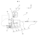
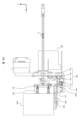
- FIG. 4 is a side view illustrating a first article transfer mechanism according to the present invention.
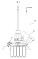
- FIG. 4 is a top view illustrating a first article transfer mechanism according to the present invention.
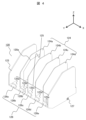
- FIG. 2 is a perspective view illustrating a first cassette according to the present invention.
- FIG. 11 is a perspective view illustrating a latch operation of the first cassette according to the present invention.
- 11 is a perspective view illustrating the operation of a first transfer unit of the first article transfer mechanism according to the present invention.
- FIG. 11 is a top view illustrating the operation of the first transfer unit of the first article transfer mechanism according to the present invention.
- FIG. 11 is a cross-sectional view for explaining the operation of a first transfer unit of a first article transfer mechanism according to the present invention, showing a state before a suction pad adapter starts moving for transfer.
- FIG. 11 is a cross-sectional view explaining the operation of the first transfer unit of the first article transfer mechanism according to the present invention, showing the state in which the latch by the latch member is released.
- FIG. 13 is a cross-sectional view illustrating the operation of the first transfer unit of the first article transfer mechanism according to the present invention, showing the state in which transfer of an article from a first cassette has begun.
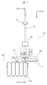
- FIG. FIG. 1 is a diagram illustrating a first item management system according to the present invention.
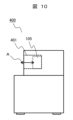
- FIG. 2 is a diagram illustrating a first item storage unit according to the present invention.
- FIG. 2 is a diagram for explaining a series of operations of the first item management system according to the present invention.
- 4 is an operation flowchart of the first item management system according to the present invention.
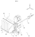
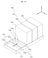
- FIG. 4 is a perspective view illustrating a second article transfer mechanism according to the present invention.
- FIG. 4 is a perspective view illustrating a second cassette according to the present invention.
- 13 is a perspective view illustrating the operation of a second transfer unit of the second article transfer mechanism according to the present invention.
- FIG. FIG. 2 is a diagram illustrating a second item management system according to the present invention.
- FIG. 4 is a diagram illustrating a second item storage unit according to the present invention.
- FIG. 4 is a diagram for explaining a series of operations of the second item management system according to the present invention.
- FIG. 2 is a diagram for explaining device cooperation in the article management system according to the present invention.
- an item transfer mechanism that handles multiple items simultaneously is effective.
- a cassette that can hold multiple items will become larger as the number of items increases.
- the item transfer mechanism has a compact configuration and can be operated with simple control, reducing the burden of introducing the item management system.
- FIGS. Fig. 1 is a perspective view for explaining a first article transfer mechanism 100 according to the present invention.
- the directions used in the explanation are as shown in Fig. 1, with the tip direction of the arrow being the positive direction and the opposite direction being the negative direction.
- the first item transfer mechanism 100 includes a first transfer section (first transfer device) 110, a first cassette 120, and an attachment/detachment jig 111.
- the first transfer section 110 includes a first item gripping and moving section (first item gripping and moving device) 130, and a first item selection and moving section (first item selection and moving device) 140.
- the first transfer section 110 is connected to a first base 114.
- the attachment/detachment jig 111 is also connected to the first base 114.
- the first cassette 120 is connected to a second base 115 (see FIG. 2) via a first linear guide 122 and a first cassette base 121.
- the first cassette 120 can also carry an item 105.
- FIG. 2 The first transfer section 110 includes a first item gripping and moving section 130, and a first item selection and moving section (first item selection and moving device) 140.
- the first transfer section 110 is connected to a first base 114.
- the attachment/detachment jig 111 is
- the item 105 is a substantially rectangular parallelepiped and may be a reagent container, a specimen test tube, a system water bottle, a cleaning solution bottle, or the like, that is used in an automatic analyzer. However, the item 105 is not limited to these.
- FIG. 2 is a side view illustrating the first article transfer mechanism 100 according to the present invention.
- the first article gripping and moving part 130 includes a joint 131, a hollow shaft 132, a first actuator 133, an actuator bracket 134, a suction pad adaptor 135, and a suction pad 136.
- the first actuator 133 linearly moves the joint 131, the hollow shaft 132, the suction pad adaptor 135, and the suction pad 136 in the direction of arrow A (Y direction).
- the actuator bracket 134 is a member that attaches the first actuator 133 to the first base 114.
- the suction pad adapter 135 has an air flow path 135a (see FIG. 8A) and supports the suction pad 136.
- One end of the hollow shaft 132 is connected to the suction pad adapter 135, and the hollow portion 132a (see FIG. 8A) of the hollow shaft 132 is connected to the air flow path 135a of the suction pad adapter 135.
- a joint 131 is provided at the other end of the hollow shaft 132.
- An air tube (not shown) is connected to the joint 131.
- the suction pad 136 is connected to the air flow path and is a part that suctions and grips an item, constituting the "item gripping section.”
- "grip” is a word that means to hold with the hand, but in this specification and claims, “grip” is not limited to holding with the hand, but is used as a term to describe the state or action of holding an item by means of suction, clamping, etc. The same applies to the "grip" of the first item gripping movement section.
- FIG. 3 is a top view illustrating the first article transfer mechanism 100 according to the present invention.
- the first item selection and moving section 140 comprises a second actuator 141, a transmission belt 142 that transmits the rotation of the second actuator 141, a third base 143, and a pulley 144 that is connected to the second actuator 141 and forms a pair of pulleys that transmit the moving force to the transmission belt 142.
- the first item selection and movement section 140 changes the relative position between the first cassette 120 and the item gripping and movement section 130 to select a particular item from the multiple items held in the first cassette 120 .
- the article selecting and moving section 140 moves the cassette 120 to change the relative position between the cassette 120 and the article gripping and moving section 130 .
- pulley 144 is one of a pair of pulleys.
- the second actuator 141 and pulley 144 are connected to a third base 143.
- the third base 143 is connected to the first base 114 in FIG. 1.
- the transmission belt 142 moves as indicated by arrow C.
- a connecting jig 145 (see FIG. 7) that connects the transmission belt 142 and the first cassette 120 moves as indicated by arrow C.
- the first cassette 120 will be described with reference to FIGS.
- FIG. 4 is a perspective view illustrating the first cassette 120 according to the present invention.
- the first cassette 120 has a first holding section 123 that holds an article.
- the first holding section 123 includes a slot 125 that is a space for holding an article, a partition plate 124 that supports both sides of an article placed in the slot 125 to prevent the article from falling over, a latch member 126 that prevents the article from flying out in the Y+ direction, and a shaft 127 (see FIG. 5 ) that fits into a through hole provided in the latch member 126.
- the partition plates 124 are, for example, 124a, 124b, 124c, and 124d. Between these partition plates are slots 125a, 125b, 125c, 125d, and 125e. Latch members 126a, 126b, 126c, 126d, and 126e are provided corresponding to these slots 125 to prevent the article from jumping out in the Y+ direction.
- the rear (Y- direction) end of the first holding portion 123 has a wall that extends in the Z+ direction, making it possible to stably hold the article in the slot 125 of the first cassette 120 so that the article does not jump out in the Y- direction.
- the first cassette 120 may be fixed to the first cassette base 121 shown in FIG. 1, or may be detachably supported by a detachable member (not shown). When the first cassette 120 is detachably supported, the items can be handled in cassette units, and the transfer time is expected to be shortened compared to when the items are handled individually.
- a warm/cold insulation device (item insulation device) 120a (not shown) may be mounted on the first cassette 120.
- a temperature detector 120b may be provided on the first cassette 120.
- the warm/cold insulation device 120a and the temperature detector 120b may be provided on all slots 125, or may be provided on a specific slot 125.
- the hot/cold insulation device 120a and the temperature detector 120b can be attached to the first cassette 120.
- the hot/cold insulation device 120a and the temperature detector 120b can be embedded in the partition plate 124 or the bottom surface (lower surface) of the first cassette 120.
- the hot/cold insulation device 120a is embedded in the partition plate 124, and the temperature detector 120b is embedded in the bottom surface (lower surface).
- the hot/cold insulation device 120a may be, for example, a pipe for passing a heat medium or an electric heating wire that is embedded.
- FIG. 5 is a perspective view illustrating the latching operation of the first cassette 120 according to the present invention.
- the latch members 126a, 126b, 126c, 126d, and 126e are supported by the shaft 127 so as to be rotatable about the axis Ax1. Therefore, like the latch member 126e, it is possible to rotate around the axis Ax1 in the direction of the arrow D to move an article in the slot 125 in the Y+ direction and an article outside the slot 125 in the Y- direction.
- the partition plate 124 is fixed. However, the position of the partition plate 124 may be supported so as to be movable in the X direction as shown by the arrows E1, E2, E3, and E4.
- the latch member 126 is configured to constantly protrude from the bottom surface of the slot 125 by a biasing member (for example, an elastic body such as a torsion spring or an actuator) not shown in the figure, and to suppress the protrusion of the article.
- a biasing member for example, an elastic body such as a torsion spring or an actuator
- Figure 6 is a perspective view explaining the operation of the first transfer unit 110 of the first article transfer mechanism 100 according to the present invention.
- Figure 7 is a top view explaining the operation of the first transfer unit 110 of the first article transfer mechanism 100 according to the present invention.
- the first cassette 120 can be moved in the direction of the arrow F by the first item selection and movement unit 140.
- the first cassette 120 is moved by the first item selection and movement unit 140 so that the axis Ax2 and the item 105e are substantially aligned in the same line.
- the first item gripping and movement unit 130 has a hollow shaft 132 that moves in the Y+ direction, and can pick up and move the item 105e in the Y+ direction.
- the hollow shaft 132 of the first item gripping and movement unit 130 can also rotate around the axis Ax2 as shown by the arrow M. By rotating the hollow shaft 132 of the first item gripping and movement unit 130 around the axis Ax2, it is possible to change the position of the item when gripping and transferring it.
- the movement of the hollow shaft 132 in the Y direction and the rotation around the axis Ax2 are performed by the first actuator 133.
- the latch mechanism 150 includes a latch member pressing material 151, a pressing material base 152 that guides the latch member pressing material 151 in the Y+ direction, a magnetic catch 153 affixed to the Y- direction surface of the suction pad adapter 135, and a magnet 154 embedded and fixed in the latch member pressing material 151 so as to face the magnetic catch 153.
- the magnetic catch 153 and the magnet 154 are held in contact with each other by magnetic force.
- the first cassette 120 is moved to transfer the article 105e, i.e., preparations are made to discharge the article from the first cassette 120.
- FIG. 8A is a cross-sectional view explaining the operation of the first transfer section 110 of the first article transfer mechanism 100 according to the present invention, and shows the state before the suction pad adapter 135 starts moving for transfer.
- the suction pad 136 is not in contact with the article 105e, and the article 105e is not being gripped by the suction pad 136.
- the first article gripping and moving section 130 moves the suction pad adapter 135 in the Y+ direction from the state shown in Fig. 8A, and the suction pad 136 grips the article 105e. This completes gripping of the article 105e by the suction pad 136.
- the latch member pressing member 151 which has been attracted to the magnet catch 153 by the magnet 154, moves in the Y+ direction in conjunction with the suction pad adapter 135. At this time, the tip inclined portion 151a of the latch member pressing member 151 comes into contact with one end (Y- direction end) 126e1 of the latch member 126e.
- FIG. 8B is a cross-sectional view for explaining the operation of the first transfer unit 110 of the first article transfer mechanism 100 according to the present invention, showing the state in which the latch by the latch member 126e has been released.
- the suction pad adapter 135 moves further in the Y+ direction from the state in Fig. 8A
- the tip inclined portion 151a of the latch member pressing member 151 rotates the latch member 126e around the shaft 127.
- the tip (Y+ direction end) of the latch member 126e moves below the bottom surface 125f of the slot 125, as shown in Fig. 8B.
- FIG. 8C is a cross-sectional view explaining the operation of the first transfer section 110 of the first article transfer mechanism 100 according to the present invention, showing the state in which transfer of the article 105e from the first cassette 120 has begun.
- the first article gripping and moving part 130 grips the article 105e and inserts it into the slot of the first cassette 120.
- the magnetic catch 153 of the suction pad adapter 135 comes into contact with the latch member pressing member 151 that has been holding the latch member 126e in place, and they are attracted by magnetic force.
- the latch member pressing material 151 with the magnet 154 embedded therein moves while being magnetically attracted to the magnetic catch 153 attached to the suction pad adapter 135, and returns to the state shown in FIG. 6 and FIG. 7. Also, as explained in FIG. 5, the latch member 126e returns from the rotated state shown in FIG. 5 to the state shown in FIG. 4 by a biasing means (not shown).
- the first article transfer mechanism 100 may use the suction pad 136 to suction and grip the article, or may use a gripper instead of the suction pad. It can be substituted with a means for gripping an article in the same manner as the suction pad 136.
- FIG. 9 is a diagram illustrating a first item management system 500 according to the present invention. 9 illustrates a case where a first item management system 500 handles two first item transfer mechanisms 100a and 100b. That is, the first item management system 500 includes a first item transfer mechanism 100a, a first item transfer mechanism 100b, a first positioning mechanism 501 to which the first item transfer mechanism 100a is detachably connected, and a first mobile body 502 that is equipped with the first positioning mechanism 501 and can move autonomously.
- the first item transfer mechanism 100a is shown in a state in which it has no items loaded, and is preparing to remove and transfer an item from the first item storage warehouse 400 shown in FIG. 10.
- the first item transfer mechanism 100b is disposed in an item transfer mechanism stocker (not shown) provided on the first moving body 502.
- the first positioning mechanism 501 positions the first item transfer mechanism 100a, removes, for example, an empty item from the first item storage warehouse 400 (not shown), and transfers the item to the first cassette 120 (see FIG. 1).
- the first positioning mechanism 501 rotates to place it in an item transfer mechanism stocker (not shown), and disconnects the first item transfer mechanism 100a.
- the first positioning mechanism 501 couples with the first positioning mechanism 100b carrying an item and rotates it.
- the first item management system 500 is moved to the first item storage facility 400 (not shown) by the first moving body 502.
- the item loaded on the first item transfer mechanism 100b is then positioned and transferred by the first positioning mechanism 501.
- the first positioning mechanism 501 has the function of rotating around the axis Ax3. This allows the attitude of the item transfer mechanisms 100a and 100b to be changed.
- the first positioning mechanism 501 rotates around the axis Ax3, making it possible to rock the item. As an example, if a liquid is enclosed in the item, rocking the item makes it possible to cause the liquid in the item to flow and mix.
- the first positioning mechanism 501 used in the first item management system 500 may be a vertical multi-joint robot with multiple rotation axes, a horizontal multi-joint robot, or an orthogonal robot (e.g., with three axes and a ⁇ axis). In this case, the positioning mechanism 501 has multiple rotation axes, or multiple linear axes and rotation axes.
- the item transfer mechanism stocker provided on the first moving body 502 may have the function of keeping the items held by the item transfer mechanisms 100a and 100b warm.
- FIG. 10 is a diagram illustrating a first item storage facility 400 according to the present invention.
- 10 shows a first item storage warehouse 400 which takes in, discharges, and stores items 105 using a first item management system 500.
- the first item storage warehouse 400 includes a first item storage slot 401.
- One or more first item storage slots 401 are provided, and it is possible to take in, discharge, and store a plurality of items 105.
- the first item storage slot 401 is also configured to allow the items 105 to be inserted and removed in the direction indicated by arrow A.
- the items 105 transferred to the first item storage warehouse 400 are rearranged to a suitable position by an item handling means in the first item storage warehouse 400, not shown.
- the first item storage facility 400 may be, for example, a refrigerator. As another example, it may be a disposal box for disposing of items. As another example, it may be an automated device that performs a task using the stored items.
- the first item storage facility 400 may take in, eject, and store the first cassette 120 (see FIG. 1) in addition to the items 105.
- the first cassette 120 may be transferred as a whole, and when transferred to another first item storage facility 400, each item may be transferred individually.
- the first item storage facility 400 may take in, eject, and store the first item transfer mechanisms 100a and 100b loaded with items.
- the first item storage facility 400 has an item transfer mechanism stocker (not shown) inside, and the first item transfer mechanisms 100a and 100b are automatically attached and detached by the first positioning mechanism 501 shown in FIG. 9.
- articles When storing the first cassette 120 and the first article transfer mechanisms 100a and 100b in the first article storage warehouse 400, articles may be loaded in advance into the first cassette 120 by an article handling mechanism (not shown) provided in the first article storage warehouse 400. In this case, since the transfer of the articles has been completed in the first article storage warehouse 400, the operation of transferring the articles can be omitted. This is expected to reduce work time.
- FIG. 11 is a diagram for explaining a series of operations of the first item management system 500 according to the present invention.
- the first item management system 500 moves to the first item storage facility 400 by the first moving body 502.
- the first positioning mechanism 501 positions the first item transfer mechanism 100 so as to be substantially directly opposite the first item storage slot 401.
- the first item transfer mechanism 100 operates the first item gripping and moving section 130 (see FIG. 1) to suction and grip the item 105.
- the first item transfer mechanism 100 moves the item 105 that it has adsorbed and gripped in the direction of the first item storage slot 401 of the first item storage cabinet 400.
- the first item transfer mechanism 100 returns the first item gripping and moving section 130 to its initial position. If there are multiple items, the first item transfer mechanism 100 uses the first item selection and moving section 140 (see FIG. 1) to select and adsorb the next item. At approximately the same time, the first positioning mechanism 501 positions the first item transfer mechanism 100 so that it is approximately directly facing another first item storage slot 401 in the first item storage facility 400. The item 105 is then transferred as described above.
- the first item transfer mechanism 100 When removing the item 105 from the first item storage 400 and transferring it to the first cassette 120 (see FIG. 1) of the first item transfer mechanism 100, the above-mentioned operations are performed in reverse order. The difference is that the first item transfer mechanism 100 operates the first item gripping and moving unit 140 without adsorbing the item 105, and causes the suction pad 136 (see FIG. 2) to enter the first item storage slot 401 to adsorb the item 105. Furthermore, when the transfer to the first item transfer mechanism 100 is completed, the first item gripping and moving unit 130 releases the suction grip of the item 105, and the latch mechanism 150 (see FIG. 8A) operates to hold the item in the slot 125 (see FIG. 4) of the first cassette 120.
- FIG. 12 is a flowchart showing the operation of the first item management system 500 according to the present invention.
- the item management system 500 starts operation upon receiving an instruction from the item collection and delivery management unit 700 shown in FIG. 19 (301).
- the instruction from the item collection and delivery management unit 700 is to transfer a specified item from a specified item storage to another item storage.
- the item management system 500 moves to the specified item storage 400 by the mobile unit 502 (302).
- the mobile unit 502 performs a positioning operation at a specified position near the item storage 400 (303).
- the positioning operation by the mobile unit 502 is not completed, the positioning operation is performed again (304 NO), and if the positioning operation is completed, the process proceeds to the next step (304 YES).
- the item transfer starts (305).
- the operation during the item transfer is as described in FIG. 11.
- the article transfer includes (1) transferring an article from the article transfer mechanism 100 to the article storage facility 400, and (2) transferring an article from the article storage facility 400 to the article transfer mechanism 100.
- it is confirmed that the goods have been transferred as instructed (306). If there are goods remaining to be transferred in the goods transfer mechanism 100, the goods transfer is deemed to be incomplete and the goods transfer is continued (306 NO).
- the process proceeds to the next step (306 YES).
- the moving body 502 moves because it is necessary to move to the next goods storage 400 (307 NO).
- the operation is completed (307 YES) (308). If an abnormality occurs during a series of operations, an alarm sound or alarm light indicating the abnormality is sounded to notify the worker, and the goods management system 500 is temporarily stopped. After the abnormality is corrected, the goods transfer is resumed.
- RFID technology may be applied.
- an IC tag with goods information written therein is attached to the goods, and a communication device capable of wirelessly reading and rewriting the information on the IC tag by radio waves or the like is provided, so that it is possible to confirm whether the target goods have been transferred appropriately.
- the item management system 500 is moving or the item transfer mechanism 100 accidentally drops an item while transferring an item, it can detect an abnormality and notify the worker, which is expected to prevent operational errors and allow work to be restarted smoothly.
- FIG. 13 is a perspective view illustrating the second article transfer mechanism 200 according to the present invention.
- the second article transfer mechanism 200 includes a second transfer section (second transfer device) 210, a second cassette 220, and an attachment/detachment jig 111 that enables the second article transfer mechanism 200 to be attached to and detached from the second positioning mechanism 511 (see FIG. 16 ).
- the second transfer section 210 includes a second article gripping and moving section (second article gripping and moving device) 230, and a second article selecting and moving section (first article selecting and moving device) 240.
- the attachment/detachment jig 111 and the second article selecting and moving section 240 are connected via a fourth base 214 and a fifth base 215 that is connected to the fourth base.
- the attachment/detachment jig 111 has been described in Example 1, so a description thereof will be omitted.
- the second cassette 220 has a second item holding section 223.
- the second item holding section 223 holds the items 205 (205a, 205b, 205c, 205d, 205e) that are transferred by the second item gripping and moving section 230.
- the second cassette 220 will be described in detail with reference to FIG. 14.
- the second item gripping and moving section 230 comprises a joint 231 to which an air tube is connected, a hollow shaft 232 to which the joint 231 is connected, a third actuator 233 which moves the hollow shaft 232 in the direction of arrow G, a sixth base 234 which has one end fixed to the third actuator 233 and the other end fixed to a second linear guide 222 fixed to the fifth base 215 and which moves in the direction of arrow H, and a suction pad (item gripping section) 236 fixed to a suction pad adapter 235.
- the suction pad adapter 235 is fixed to the end of the hollow shaft 232 opposite the end to which the joint 231 is connected.
- the suction pad 236 communicates with the air flow path provided in the joint 231, hollow shaft 232, and suction pad adapter 235, and suction-holds the article 205.
- the second item selection and movement section 240 includes a fourth actuator 241 that moves the second item gripping and movement section 230, a pulley 245 connected to the fourth actuator 241, a pulley 244 that faces the pulley 245 in the direction of arrow K, a transmission belt 242 that connects the pulley 244 and the pulley 245 to transmit the power of the fourth actuator 241, and a seventh base 243 that fixes the fourth actuator 241 to a shaft (not shown) that supports the pulley 244.
- the second item selection and movement unit 240 can move the second item gripping and movement unit 230 in the direction of arrow K by rotating the fourth actuator 241 in the direction of arrow J.
- the first item selection and movement section 140 changes the relative position between the first cassette 120 and the item gripping and movement section 130 to select a particular item from the multiple items held in the first cassette 120 .
- the article selecting and moving section 240 moves the article gripping and moving section 230 to change the relative position between the cassette 220 and the article gripping and moving section 230 .
- the hollow shaft 232 of the second item gripping and moving section 230 can be rotated around the Z axis by the third actuator 233, as shown by the arrow N. By rotating the hollow shaft 232 around the Z axis, it is possible to change the posture of the item 205 when gripping and transferring the item 205.
- Item 205 is roughly rectangular, and may be a reagent container, specimen test tube, system water bottle, or cleaning liquid bottle used in an automatic analyzer or the like. However, item 205 is not limited to these.
- FIG. 14 is a perspective view illustrating a second cassette 220 according to the present invention.
- the second cassette 220 has slots 225 (225a, 225b) capable of stably holding the articles 205 (205c, 205d, 205e).
- the slots 225 have partitions 224 (224a, 224b) for stably holding the articles.
- the partitions 224 are usually fixed. However, the partitions 224 may be supported so as to be movable in the direction indicated by the arrow L. In this case, it is also possible to hold (mix) the articles 205 having different lengths in the Y direction.
- the second cassette 220 may be fixed to the fifth base 215, or may be removably supported by a removable part (not shown).
- the items can be handled on a cassette basis, which is expected to reduce the transfer time compared to handling individual items.
- a hot/cold keeping device (article keeping device) (not shown) may be mounted in the second cassette 220 or each slot 225.
- a temperature detector may be provided in the second cassette 220 or each slot 225.
- the hot/cold insulation device and the temperature detector can be assembled in the cassette 220, for example, by making the cassette 220 have a heater and a temperature detector embedded therein.
- a warm/cold insulation device (item insulation device) 220a may be mounted on the second cassette 220. If temperature control is required, a temperature detector 220b may be provided on the second cassette 220. The warm/cold insulation device 220a and the temperature detector 220b may be provided on all slots 225 or on specific slots 225. In this case, the warm/cold insulation device 220a and the temperature detector 220b can be assembled on the second cassette 220. For example, the warm/cold insulation device 220a and the temperature detector 220b can be embedded in the partition plate 224 or the bottom surface (lower surface) of the second cassette 220.
- the warm/cold insulation device 120a and the temperature detector 120b are embedded on the bottom surface (lower surface).
- a pipe for flowing a heat medium or a heating wire may be embedded as the warm/cold insulation device 220a.
- FIG. 15 is a perspective view for explaining the operation of the second transfer unit 210 of the second article transfer mechanism 200 according to the present invention.
- the upper left diagram of FIG. 15 shows the initial position of the second item transfer mechanism 200. Five items are loaded in the second cassette 220. The second item gripping and moving section 230 is moved in the Y- direction by the second item selecting and moving section 240. The second item transfer mechanism 200 is positioned near a slot in the second item storage to which the items are to be transferred by the second positioning mechanism 511 of the item management system 510 described in FIG. 16.
- FIG. 15 illustrates an example of the transfer of an item at the end in the Y+ direction.
- the second item selecting and moving section 240 starts moving in the Y+ direction of the arrow H to adsorb and grip the item.
- FIG. 15 shows the state in which the second item gripping and moving section 230 has been moved by the second item selection and moving section 240 to approximately directly above the item to be transferred. From this state, the hollow shaft 232 is moved in the Z- direction of the arrow G, so that the second item gripping and moving section 230 adsorbs and grips the item, as shown in the upper right diagram of FIG. 15. Next, while adsorbing and gripping the item, the hollow shaft 232 is moved in the Z+ direction of the arrow G, and the item is removed from the slot 225 of the second cassette 220, as shown in the lower left diagram of FIG. 15.
- the second item selection and moving section 240 is moved in the Y+ direction of the arrow H, so that the item is moved outside the second cassette 220, as shown in the lower middle diagram of FIG. 15.
- the hollow shaft 232 is moved further in the Z- direction of the arrow G, so that the item is moved in the Z- direction, as shown in the lower right diagram of FIG. 15, and transferred to the item storage slot 601 (see FIG. 17) of the second item storage facility 600.
- the second item transfer mechanism 200 may use the suction pad 236 to suction-hold the item, or may use a gripper instead of the suction pad.
- the suction pad 236 may be replaced with a means for holding an item in the same manner as the suction pad 236.
- FIG. 16 is a diagram illustrating a second item management system 510 according to the present invention. 16 illustrates a case where the second item management system 510 handles two second item transfer mechanisms 200a and 200b. That is, the second item management system 510 includes the second item transfer mechanism 200a, the second item transfer mechanism 200b, a second positioning mechanism 511 to which the second item transfer mechanism 200a is detachably connected, and a second mobile body 512 that is equipped with the second positioning mechanism 511 and can move autonomously.
- the second item transfer mechanism 200a is shown in a state in which it has no items loaded, and is preparing to remove and transfer an item from the second item storage facility 600 shown in FIG. 17.
- the second item transfer mechanism 200b is disposed in an item transfer mechanism stocker (not shown) provided on the second moving body 512.
- the second positioning mechanism 511 positions the second item transfer mechanism 200a, removes, for example, an empty item from the second item storage facility 600 (not shown), and transfers the item to the second cassette 220 (see FIG. 13).
- the second positioning mechanism 511 rotates to place it in an item transfer mechanism stocker (not shown), and disconnects the second item transfer mechanism 200a.
- the second positioning mechanism 511 couples and rotates the second positioning mechanism 200b carrying an item.
- the second item management system 510 is moved to the second item storage facility 600 (not shown) by the second moving body 512.
- the item loaded on the second item transfer mechanism 200b is then positioned and transferred by the second positioning mechanism 511.
- the second positioning mechanism 511 has the function of rotating around the axis Ax4. This makes it possible to change the attitude of the item transfer mechanisms 200a, 200b.
- the second positioning mechanism 511 rotates around the axis Ax4, making it possible to rock the item. As an example, if a liquid is enclosed in the item, rocking the item makes it possible to cause the liquid in the item to flow and mix.
- the second positioning mechanism 511 used in the second item management system 510 may be a vertical multi-joint robot with multiple rotation axes, a horizontal multi-joint robot, or an orthogonal robot (e.g., with three axes and a ⁇ axis). In this case, the positioning mechanism 511 has multiple rotation axes, or multiple linear axes and rotation axes.
- the item transfer mechanism stocker provided on the second moving body 512 may have the function of keeping the items held by the item transfer mechanisms 200a and 200b warm.
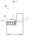
- FIG. 17 is a diagram illustrating a second item storage cabinet 600 according to the present invention.
- the second item storage cabinet 600 includes a second item storage slot 601.
- One or more second item storage slots 601 are provided, and are capable of taking in, discharging, and storing a plurality of items 205.
- the second item storage slot 601 is configured to allow the items 205 to be put in and taken out in the direction indicated by the arrow G.
- the items 205 transferred to the second item storage cabinet 600 are rearranged to suitable positions by an item handling means in the second item storage cabinet 400, not shown.
- Arrow H indicates the direction of movement of the second item transfer mechanisms 200a, 200b.
- the second item transfer mechanisms 200a, 200b transfer items 205 to the second item storage slot 601 while moving in the direction of arrow H.
- the second item storage 600 may be, for example, a refrigerator. As another example, it may be a disposal box for disposing of items. As another example, it may be an automated device that performs work using stored items.
- the second item storage facility 600 may take in, take out, and store the second cassette 220 in addition to the items 205.
- the second cassette 220 may be transferred as a whole, and when transferred to another second item storage facility 600, each item may be transferred individually.
- the second item storage facility 600 may take in, eject, and store the second item transfer mechanisms 200a and 200b loaded with items.
- the second item storage facility 600 has an item transfer mechanism stocker (not shown) inside, and the second item transfer mechanisms 200a and 200b are automatically attached and detached by the second positioning mechanism 511 shown in FIG. 16.
- items When storing the second cassette 220 and the second item transfer mechanisms 200a, 200b in the second item storage facility 600, items may be loaded in advance into the second cassette 220 by an item handling mechanism (not shown) provided in the first item storage facility 600. In this case, since the transfer of items has been completed in the second item storage facility 600, the item transfer operation can be omitted. This is expected to reduce the work time.
- FIG. 18 is a diagram for explaining a series of operations of the second item management system 510 according to the present invention.
- A An example of the initial position during transfer of the second item management system 510 is shown.
- the item 205 is to be transferred to the far right of the second item storage slot 601. Therefore, the second positioning mechanism 511 of the second item management system 510 positions the second item transfer mechanism 200 so as to provide a space at the far left where the item can be transferred.
- the second item management system 510 and the second item storage 600 have been described in Figures 16 and 17, respectively, so an explanation thereof will be omitted.
- the second item transfer mechanism 200 moves the second item gripping and moving part 230 to approximately directly above the item 205 to be transferred.
- the second item transfer mechanism 200 adsorbs and grasps the item 205 using the second item grasping and moving part 230.
- the second item transfer mechanism 200 removes the item 205 from the second cassette 220.
- the second item transfer mechanism 200 moves the item 205 removed from the second cassette 220 to approximately directly above the target second item storage slot 601 using the second item selection and movement unit 240.
- the second item transfer mechanism 200 transfers the item 205 to the second item storage slot 601 by the second item gripping and moving part 230.
- the second item transfer mechanism 200 When the transfer of the item to the second item storage slot 601 is completed, the second item transfer mechanism 200 returns the second item gripping and moving unit 230 to its initial position. When there are multiple items as in FIG. 18, the second item transfer mechanism 200 selects and adsorbs and grips the next item using the second item selection and moving unit 240 and the second item gripping and moving unit 230. At roughly the same time, the second positioning mechanism 511 positions the second item transfer mechanism 200 at a position where the item can be transferred to another second item storage slot 601 in the second item storage facility 600. Then, the item 205 is transferred as described above.
- the above-mentioned operations are performed in reverse order.
- the second item transfer mechanism 200 operates the second item gripping and moving unit 230 without adsorbing the item 205, and causes the suction pad 236 to enter the second item storage slot 601 to adsorb the item 205.
- the second item gripping and moving unit 230 releases the suction grip of the item 205.
- the above operations perform the item transfer operation as shown in the flowchart described with reference to FIG. 12 in Example 1.
- FIG. 19 is a diagram for explaining device cooperation between item management systems 500 and 510 according to the present invention.
- Figure 19 shows an example of device collaboration in an item management system, showing collaboration between a first item storage facility 400, a second item storage facility 600, a first item management system 500, a second item management system 510, and an item collection and delivery management unit 700.
- the item collection and delivery management unit 700 has information on items stored in the first item storage warehouse 400 and the second item storage warehouse 600.
- the item information is information necessary for item management, such as the type of item, manufacturing date, and usage history.
- the item information is managed by applying the RFID technology described in Figure 12, attaching IC tags containing item information to the items, and reading and writing the information through communication using a separately provided communication device.
- the item collection and delivery management unit 700 monitors the storage status of items by communicating with the item management systems and item storage warehouses. If there is a shortage of items, the item collection and delivery system 700 issues an item management system command to retrieve items from the relevant item storage warehouse. Upon receiving the command, the item management system stores the items in the specified item storage warehouse. As explained above, the item management systems 500, 510 collect and deliver items based on item information.
- the above-described embodiment of the present invention has the following features.
- the article transfer mechanisms 100 and 200 are A cassette 120, 220 on which a plurality of articles 105, 205 are placed; an article gripping and moving unit 130, 230 that grips and moves the article 105, 205; an article selection and movement unit (140, 240) that changes the relative positions of the cassette (120, 220) and the article gripping and movement unit (130, 230) to select a specific article from the multiple articles (105, 205) held in the cassette (120, 220); Equipped with The article selection and movement unit 140, 240 changes the relative positions of the cassette 120, 220 and the article gripping and movement unit 130, 230 to select the article 105, 205 to be transferred, The article gripping and moving unit 130, 230 transfers the selected article 105, 205 by holding and moving the article.
- the item selection and movement unit 140 moves the cassette 120 to change the relative position between the cassette 120 and the item gripping and movement unit 130.
- the item selection and movement unit 240 moves the item gripping and movement unit 230 to change the relative position between the cassette 220 and the item gripping and movement unit 230.
- the cassette 120, 220 includes a plurality of slots 125, 225 for holding articles and a partition plate 124, 224 that defines the plurality of slots 125, 225,
- the partition plates 124, 224 are movably supported so that the slot size can be changed.
- the article gripping and moving unit 130 includes an article gripping unit 136 that grips an article and moves in the article transfer direction
- the cassette 120 includes: a plurality of slots 125 for holding items;
- a latch member 126 is disposed on a path for inserting and removing the article and prevents the article from falling out of the slot 125;
- a shaft 127 that rotatably supports the latch member 126; Equipped with The latch member 126 is configured to rotate in conjunction with the movement of the article gripping portion 136 .
- the cassettes 120 and 220 are equipped with item insulation devices 120a and 220a.
- the cassettes 120 and 220 are provided with temperature detectors 120b and 220b in multiple slots 125 and 225.
- the article gripping and moving unit 130, 230 is A suction pad 136, 236 for suction-holding an article; a suction pad adapter 135, 235 supporting the suction pad 136, 236 and having an air flow passage; a hollow shaft 132, 232 connected to the air flow path 135a of the suction pad adapter 135, 235 and having a joint 131, 231 at the other end;
- the actuators 133, 233 move the hollow shafts 132, 232 in the axial direction of the hollow shafts and rotate the hollow shafts around their axes.
- the inventory management system is Positioning mechanisms 501 and 511 for positioning the article transfer mechanisms 100 and 200; Autonomously movable mobile bodies 502 and 512 each having a positioning mechanism 501 or 511 mounted thereon; An item storage facility 400, 600 for storing items; Equipped with To transfer a plurality of articles between a plurality of article storage units.
- the positioning mechanisms 501 and 511 have multiple rotation axes.
- the positioning mechanisms 501 and 511 have multiple linear axes and rotational axes.
- the item management system includes an item collection and delivery management unit 700, and transfers multiple items between multiple item storage units 400, 600 based on work instructions issued by the item collection and delivery management unit 700.
- the burden on the worker can be reduced by the item transfer mechanism that can efficiently replace multiple items.
- the item transfer mechanism that can load multiple items and sequentially load and unload the items can reduce work time.
- items can be loaded and unloaded in a short time, the impact of the surrounding environment on the items can be reduced.
- the teaching time of the item management system by the worker (the time it takes for the worker to instruct the item management system in advance on a series of operations) can be reduced.
- the present invention is not limited to the above-described embodiments, but includes various modified examples.
- the above-described embodiments have been described in detail to clearly explain the present invention, and are not necessarily limited to those including all of the configurations. It is also possible to replace part of the configuration of one embodiment with the configuration of another embodiment, and it is also possible to add the configuration of another embodiment to the configuration of one embodiment. It is also possible to add, delete, or replace part of the configuration of each embodiment with other configurations.
Landscapes
- Engineering & Computer Science (AREA)
- Robotics (AREA)
- Mechanical Engineering (AREA)
- Warehouses Or Storage Devices (AREA)
- Manipulator (AREA)
Abstract
本発明の目的は、ハンド部とマニピュレータとの動作の連動を必要とせず、物品移載を短時間で効率よく行うことができる物品移載機構を提供することにある。 本発明の物品移載機構は、複数の物品を載置するカセット120と、物品を把持して移動させる物品把持移動部130と、カセット120と物品把持移動部130との相対位置を変化させてカセット120に保持された複数の物品105から特定の物品を選択する物品選択移動部140と、を備える。物品選択移動部140は、カセット120と物品把持移動部130との相対位置を変化させて移載対象となる物品を選択する。物品把持移動部140は、選択された物品を保持して移動させる。
Description
本発明は、物品を移載する物品移載機構、および物品移載機構を備えた物品管理システムに関する。
特許文献1には、複数種類の試薬などの消耗品を分析ユニットや格納庫、廃棄容器、作業台などの間で搬送するとともに、投入や排出に関連する一連の作業を実施する自律移動ロボットが記載されている(段落0029参照)。特許文献1の自律移動ロボットは、例えば、形状、文字、輝度、あるいは色を認識できる、カメラなどの画像入力デバイスを眼の役割として備える頭部と、自律移動ロボットを移動させるための駆動部と、物品の一時保管や処理作業を実施可能なスペースを備えた荷台部と、頭部を360度回転して全方位を画像入力デバイスで見渡すための回転機構と、伸縮可能なアーム部と、物品の把持やボタンの押下などを行うハンド部と、搬送品を保持する保管棚と、を備えている(段落0029参照)。
特許文献1の自律移動ロボットは、複数の装置と、様々な物品を保管する格納庫と、搬送品を保管する保管棚と、不要品を廃棄する廃棄容器と、の間で物品を移載する際に、ハンド部が物品を把持して、物品を一つずつ移載する。また、物品を搬送する場合には、自律移動ロボットの荷台部に物品を一つずつ移載して保管棚に一時保管して搬送する。複数の物品を取り扱う場合、格納庫から保管棚へ、保管棚から装置へ、或いは保管棚から廃棄容器へ、物品を移載しようとすると、アーム(マニピュレータ)部先端に取り付けられたハンド部が繰り返し動作を行うことになる。格納庫と保管棚との間、装置と保管棚との間、或いは廃棄容器と保管棚との間を、マニピュレータが往復動作する回数が増加するにつれて(物品数が増えるにつれて)、動作時間が増大する。また、マニピュレータ動作も複雑になり、動作生成に要する時間が長くなる。さらに、ハンド部は物品の把持のみを行うため、装置、格納庫、保管棚、或いは廃棄容器に対する物品の出し入れ動作をマニピュレータが行う必要がある。特許文献1の自律移動ロボット(物品移載機構)は、ハンド部による物品単体の把持と、物品を移載する動作を担うマニピュレータと、で構成され、物品を移載するためには、ハンド部とマニピュレータの双方を連動させることが必要であった。
本発明の目的は、ハンド部とマニピュレータとの動作の連動を必要とせず、物品移載を短時間で効率よく行うことができる物品移載機構を提供することにある。
上記目的を達成するために、本発明の物品移載機構の一例は、
複数の物品を載置するカセットと、
物品を把持して移動させる物品把持移動部と、
前記カセットと前記物品把持移動部との相対位置を変化させて前記カセットに保持された複数の物品から特定の物品を選択する物品選択移動部と、
を備え、
前記物品選択移動部は、前記カセットと前記物品把持移動部との相対位置を変化させて移載対象となる物品を選択し、
前記物品把持移動部は、選択された物品を保持して移動させることで物品を移載する。
また、物品管理システムは、前記物品移載機構と、前記物品移載機構を位置決めする位置決め機構と、前記位置決め機構を搭載して自律移動する移動体と、物品を保管する物品保管庫と、を備える。
複数の物品を載置するカセットと、
物品を把持して移動させる物品把持移動部と、
前記カセットと前記物品把持移動部との相対位置を変化させて前記カセットに保持された複数の物品から特定の物品を選択する物品選択移動部と、
を備え、
前記物品選択移動部は、前記カセットと前記物品把持移動部との相対位置を変化させて移載対象となる物品を選択し、
前記物品把持移動部は、選択された物品を保持して移動させることで物品を移載する。
また、物品管理システムは、前記物品移載機構と、前記物品移載機構を位置決めする位置決め機構と、前記位置決め機構を搭載して自律移動する移動体と、物品を保管する物品保管庫と、を備える。
本発明によれば、ハンド部とマニピュレータとの動作の連動を必要とせず、物品移載を短時間で効率よく行うことができる物品移載機構を提供することができる。
上記した以外の課題、構成及び効果は、以下の実施形態の説明により明らかにされる。
上記した以外の課題、構成及び効果は、以下の実施形態の説明により明らかにされる。
複数の物品を効率よく交換して作業時間を少なくするためには、複数の物品を同時に取り扱う物品移載機構が有効である。そのためには、複数の物品を保持可能なカセットを有することが望ましい。複数の物品を保持可能なカセットは、物品数を増加させると、カセット自体が大型化してしまう懸念がある。この課題を解決するためには、カセットや物品移載機構を着脱可能な構造とすることが有効である。すなわち、物品数や取扱う物品種類の増加に対して、カセットまたは物品移載機構を複数用意し、自動で交換できるようにすることで、作業者業務を代替して作業負担を軽減する物品管理システムを提供することができる。また、物品移載機構は、コンパクトな構成で、シンプルな制御で運用できるため、物品管理システムの導入時の負担が軽減される。
[実施例1]
本発明の第1実施例を図1から図12を参照し説明する。
最初に図1から図3を参照して、第一物品移載機構100の基本構成を説明する。
図1は本発明に係る第一物品移載機構100を説明する斜視図である。説明で用いる方向は図1中に示す通りであり、矢印の先端方向を正方向、反対方向を負方向とする。
本発明の第1実施例を図1から図12を参照し説明する。
最初に図1から図3を参照して、第一物品移載機構100の基本構成を説明する。
図1は本発明に係る第一物品移載機構100を説明する斜視図である。説明で用いる方向は図1中に示す通りであり、矢印の先端方向を正方向、反対方向を負方向とする。
第一物品移載機構100は、第一移載部(第一移載装置)110と、第一カセット120と、着脱治具111と、を備える。第一移載部110は、第一物品把持移動部(第一物品把持移動装置)130と、第一物品選択移動部(第一物品選択移動装置)140と、を備える。第一移載部110は、第一ベース114と連結されている。また、着脱治具111は、同じく第一ベース114と連結されている。第一カセット120は、第一直動ガイド122および第一カセットベース121を介して、第二ベース115(図2参照)と連結されている。また、第一カセット120は、物品105を搭載可能である。図1中では、物品105として、物品105a、105b、105c、105d、105eが第一カセット120に載置されている。物品105は、略直方体で、自動分析装置などに用いられる、試薬容器、検体試験管、システム水ボトル、洗浄液ボトル等であって良い。しかし、物品105はこれらに限定されるものでははい。
図2は本発明に係る第一物品移載機構100を説明する側面図である。
第一物品把持移動部130は、継ぎ手131と、中空シャフト132と、第一アクチュエータ133と、アクチュエータブラケット134と、吸着パッドアダプタ135と、吸着パッド136と、を備える。第一アクチュエータ133は、継ぎ手131、中空シャフト132、吸着パッドアダプタ135、および吸着パッド136を矢印A方向(Y方向)に直線的に移動させる。アクチュエータブラケット134は、第一アクチュエータ133を第一ベース114に取り付ける部材である。
第一物品把持移動部130は、継ぎ手131と、中空シャフト132と、第一アクチュエータ133と、アクチュエータブラケット134と、吸着パッドアダプタ135と、吸着パッド136と、を備える。第一アクチュエータ133は、継ぎ手131、中空シャフト132、吸着パッドアダプタ135、および吸着パッド136を矢印A方向(Y方向)に直線的に移動させる。アクチュエータブラケット134は、第一アクチュエータ133を第一ベース114に取り付ける部材である。
吸着パッドアダプタ135は、空気流路135a(図8A参照)を備え、吸着パッド136を支持する。中空シャフト132はその一端部が吸着パッドアダプタ135に連結され、中空シャフト132の中空部132a(図8A参照)が吸着パッドアダプタ135の空気流路135aと連通される。中空シャフト132は、他端部に継ぎ手131が設けられる。継ぎ手131には図示しない空気チューブが連結される。
吸着パッド136は、空気流路に連結されて物品を吸着把持する部位であり、「物品把持部」を構成する。ここで、「把持」とは手で握ることを意味する言葉であるが、本明細書及び特許請求の範囲では、「把持」は手で握ることに限らず、例えば吸着や挟持等の手段によって物品を保持する状態又は動作を表す用語として用いる。第一物品把持移動部の「把持」も同様である。
図3は本発明に係る第一物品移載機構100を説明する上面図である。
第一物品選択移動部140は、第二アクチュエータ141と、第二アクチュエータ141の回転を伝達する伝動ベルト142と、第三ベース143と、第二アクチュエータ141に接続されて伝動ベルト142に移動力を伝えるプーリの対となるプーリ144と、を備える。
第一物品選択移動部140は、第二アクチュエータ141と、第二アクチュエータ141の回転を伝達する伝動ベルト142と、第三ベース143と、第二アクチュエータ141に接続されて伝動ベルト142に移動力を伝えるプーリの対となるプーリ144と、を備える。
第一物品選択移動部140は、第一カセット120と物品把持移動部130との相対位置を変化させて第一カセット120に保持された複数の物品から特定の物品を選択する。
本実施例では、物品選択移動部140は、カセット120を移動させてカセット120と前記物品把持移動部130との相対位置を変化させる。
本実施例では、物品選択移動部140は、カセット120を移動させてカセット120と前記物品把持移動部130との相対位置を変化させる。
なお、プーリ144は、対となるプーリのうち、一方のプーリを図示している。第二アクチュエータ141およびプーリ144は、第三ベース143と連結されている。また、第三ベース143は、図1の第一ベース114に連結されている。第二アクチュエータ141が矢印BのごとくZ方向軸まわりに回転することで、伝動ベルト142が矢印Cのごとく移動する。伝動ベルト142が移動すると、伝動ベルト142と第一カセット120とを連結する連結治具145(図7参照)が矢印Cのごとく移動する。
図4および図5を参照して、第一カセット120について説明する。
図4は、本発明に係る第一カセット120を説明する斜視図である。
第一カセット120は、物品を保持する第一保持部123を有する。第一保持部123は、物品を保持する空間であるスロット125と、スロット125に入れられた物品の両側面を倒れないように支持する仕切り板124と、物品がY+方向に飛び出すことを防止するラッチ部材126と、ラッチ部材126に設けた貫通孔に勘合するシャフト127(図5参照)と、を備える。
図4は、本発明に係る第一カセット120を説明する斜視図である。
第一カセット120は、物品を保持する第一保持部123を有する。第一保持部123は、物品を保持する空間であるスロット125と、スロット125に入れられた物品の両側面を倒れないように支持する仕切り板124と、物品がY+方向に飛び出すことを防止するラッチ部材126と、ラッチ部材126に設けた貫通孔に勘合するシャフト127(図5参照)と、を備える。
仕切り板124は、例えば、124a、124b、124c、124dである。これらの仕切り板の間は、スロット125a、125b、125c、125d、125eである。これらのスロット125に対応して、ラッチ部材126a、126b、126c、126d、126eが設けられ、物品のY+方向への飛び出しを抑止する。なお、第一保持部123の背面(Y-方向)端部は、Z+方向に延伸する壁を有しており、物品がY-方向に飛び出すことがないように、物品を安定して第一カセット120のスロット125に保持することが可能である。
第一カセット120は、図1に示した第一カセットベース121に固定されていても良いし、図示していない着脱部材により着脱可能に支持されていても良い。第一カセット120が着脱可能に支持されている場合、カセット単位で物品を取扱うことができるため、物品単体で取扱う場合と比べると、移載時間が短縮される効果が期待される。また、物品を温冷保温する必要がある場合、図示していない温冷保温装置(物品保温装置)120aを第一カセット120に搭載しても良い。また、温度管理を必要とする場合、温度検出器120bを第一カセット120に設けてもよい。温冷保温装置120a及び温度検出器120bは、全スロット125に設けても良いし、特定のスロット125に設けてもよい。
この場合、温冷保温装置120a及び温度検出器120bは第一カセット120に組み付けることができる。例えば、第一カセット120の仕切り板124または底面(下面)に、温冷保温装置120a及び温度検出器120bを埋設することができる。本実施例では、仕切り板124に温冷保温装置120aを埋設し、底面(下面)に温度検出器120bを埋設している。温冷保温装置120aとして、例えば、熱媒体を流す配管または電熱線等を埋設すればよい。
この場合、温冷保温装置120a及び温度検出器120bは第一カセット120に組み付けることができる。例えば、第一カセット120の仕切り板124または底面(下面)に、温冷保温装置120a及び温度検出器120bを埋設することができる。本実施例では、仕切り板124に温冷保温装置120aを埋設し、底面(下面)に温度検出器120bを埋設している。温冷保温装置120aとして、例えば、熱媒体を流す配管または電熱線等を埋設すればよい。
図5は、本発明に係る第一カセット120のラッチ動作を説明する斜視図である。
ラッチ部材126a、126b、126c、126d、126eは、軸Ax1を回転中心として回動可能に、シャフト127に支持されている。そのため、ラッチ部材126eのように、矢印Dの方向に軸Ax1まわりに回動して、スロット125内にある物品をY+方向に移動したり、外部の物品をY-方向へ移動したりすることが可能である。図5では、仕切り板124は固定されている。しかし、仕切り板124の位置は、矢印E1、E2、E3、E4のようにX方向に移動可能に支持されていても良い。また、図示していない付勢部材(例えば、ねじりばねのような弾性体やアクチュエータ)により、ラッチ部材126は、定常的にスロット125の底面より飛び出し、物品の飛び出しを抑制するように構成されている。しかし、図8で説明するラッチ機構により、矢印Dの両方向に移動するようにするも可能である。
ラッチ部材126a、126b、126c、126d、126eは、軸Ax1を回転中心として回動可能に、シャフト127に支持されている。そのため、ラッチ部材126eのように、矢印Dの方向に軸Ax1まわりに回動して、スロット125内にある物品をY+方向に移動したり、外部の物品をY-方向へ移動したりすることが可能である。図5では、仕切り板124は固定されている。しかし、仕切り板124の位置は、矢印E1、E2、E3、E4のようにX方向に移動可能に支持されていても良い。また、図示していない付勢部材(例えば、ねじりばねのような弾性体やアクチュエータ)により、ラッチ部材126は、定常的にスロット125の底面より飛び出し、物品の飛び出しを抑制するように構成されている。しかし、図8で説明するラッチ機構により、矢印Dの両方向に移動するようにするも可能である。
図6および図7を参照して、第一物品移載機構100の第一移載部110の動作について説明する。図6は、本発明に係る第一物品移載機構100の第一移載部110の動作を説明する斜視図である。図7は、本発明に係る第一物品移載機構100の第一移載部110の動作を説明する上面図である。
第一カセット120は、第一物品選択移動部140により、矢印F方向に移動させることができる。物品105eの移載は、第一物品選択移動部140により、第一カセット120を軸Ax2と物品105eとが略同一直線上となるように移動させる。第一物品把持移動部130は、Y+方向に中空シャフト132が移動し、物品105eを吸着してY+方向に移動させることができる。また、第一物品把持移動部130の中空シャフト132は、矢印Mで示すように、軸Ax2まわりに回転することが可能である。第一物品把持移動部130の中空シャフト132が軸Ax2まわりに回転することにより、物品を把持して移載する際に物品の姿勢を変更することが可能である。中空シャフト132のY方向における移動、および軸Ax2まわりの回転は、第一アクチュエータ133によって行われる。
図8A、図8B及び図8Cを参照して、引き続き第一物品移載機構100の第一移載部110の動作について説明する。
ラッチ機構150は、ラッチ部材押圧材151と、ラッチ部材押圧材151をY+方向にガイドする押圧材ベース152と、吸着パッドアダプタ135のY-方向面に貼付されたマグネットキャッチ153と、マグネットキャッチ153と正対するようにラッチ部材押圧材151に埋め込まれて固定されたマグネット154と、を備える。図6および図7の状態は、マグネットキャッチ153とマグネット154とは磁力により接触保持されている。図6および図7で第一カセット120を移動させて、物品105eを移載する、すなわち物品を第一カセット120から排出する準備が整う。
ラッチ機構150は、ラッチ部材押圧材151と、ラッチ部材押圧材151をY+方向にガイドする押圧材ベース152と、吸着パッドアダプタ135のY-方向面に貼付されたマグネットキャッチ153と、マグネットキャッチ153と正対するようにラッチ部材押圧材151に埋め込まれて固定されたマグネット154と、を備える。図6および図7の状態は、マグネットキャッチ153とマグネット154とは磁力により接触保持されている。図6および図7で第一カセット120を移動させて、物品105eを移載する、すなわち物品を第一カセット120から排出する準備が整う。
図8Aは、本発明に係る第一物品移載機構100の第一移載部110の動作を説明する断面図であり、吸着パッドアダプタ135が移載のための移動を開始する前の状態を示す図である。
図8Aでは吸着パッド136は物品105eに接触しておらず、物品105eは吸着パッド136によって把持されていない状態である。第一物品把持移動部130は、図8Aに示す状態から吸着パッドアダプタ135をY+方向に移動させて、吸着パッド136で物品105eを吸着する。これにより、吸着パッド136による物品105eの把持が完了する。これと同時に、マグネット154によってマグネットキャッチ153に吸着されたラッチ部材押圧材151は、吸着パッドアダプタ135と連動してY+方向に移動する。このとき、ラッチ部材押圧材151の先端傾斜部151aと、ラッチ部材126eの一端部(Y-方向端部)126e1とが接触する。
図8Aでは吸着パッド136は物品105eに接触しておらず、物品105eは吸着パッド136によって把持されていない状態である。第一物品把持移動部130は、図8Aに示す状態から吸着パッドアダプタ135をY+方向に移動させて、吸着パッド136で物品105eを吸着する。これにより、吸着パッド136による物品105eの把持が完了する。これと同時に、マグネット154によってマグネットキャッチ153に吸着されたラッチ部材押圧材151は、吸着パッドアダプタ135と連動してY+方向に移動する。このとき、ラッチ部材押圧材151の先端傾斜部151aと、ラッチ部材126eの一端部(Y-方向端部)126e1とが接触する。
図8Bは、本発明に係る第一物品移載機構100の第一移載部110の動作を説明する断面図であり、ラッチ部材126eによるラッチを解除した状態を示す図である。
図8Aの状態からさらに、吸着パッドアダプタ135がY+方向に移動すると、ラッチ部材押圧材151の先端傾斜部151aは、ラッチ部材126eをシャフト127まわりに回動させる。これにより、図8Bのように、ラッチ部材126eの先端(Y+方向端部)は、スロット125の底面125fより下方に移動する。
図8Aの状態からさらに、吸着パッドアダプタ135がY+方向に移動すると、ラッチ部材押圧材151の先端傾斜部151aは、ラッチ部材126eをシャフト127まわりに回動させる。これにより、図8Bのように、ラッチ部材126eの先端(Y+方向端部)は、スロット125の底面125fより下方に移動する。
図8Cは、本発明に係る第一物品移載機構100の第一移載部110の動作を説明する断面図であり、物品105eの第一カセット120からの移載を開始した状態を示す図である。
さらに、図8Cのように、吸着パッドアダプタ135がY+方向に移動すると、物品105eは第一カセット120から移載される。このとき、シャフト127まわりに回動したラッチ部材126eの一端部126e1は、第一カセット120の下部と接触して回動を停止する。これと同時に、ラッチ部材126eを回動させる力を付与したラッチ部材押圧材151は、ラッチ部材126eの一端部126e1によりY+方向への移動が止められ、吸着パッドアダプタ135から離間して停止する。その結果、ラッチ部材126eは、回動した状態、すなわち、物品105eを移載可能な状態に保持される。
物品105eを第一カセット120に挿入する場合、第一物品把持移動部130により物品105eを把持して第一カセット120のスロット内に挿入する。図8Bの状態になった時、吸着パッドアダプタ135のマグネットキャッチ153と、ラッチ部材126eを固定保持していたラッチ部材押圧材151とが接触し、磁力により吸着する。
物品105eを第一カセット120に挿入する場合、第一物品把持移動部130により物品105eを把持して第一カセット120のスロット内に挿入する。図8Bの状態になった時、吸着パッドアダプタ135のマグネットキャッチ153と、ラッチ部材126eを固定保持していたラッチ部材押圧材151とが接触し、磁力により吸着する。
さらに図8Aのように吸着パッドアダプタ135が移動すると、マグネット154を埋め込まれたラッチ部材押圧材151は、吸着パッドアダプタ135に貼付したマグネットキャッチ153に磁力吸着した状態で移動し、図6および図7の状態に復帰する。また、ラッチ部材126eは、図5で説明したように、図示していない付勢手段により、図5の回動状態から復帰して図4の状態となる。
第一物品移載機構100は、吸着パッド136で物品を吸着把持しても良いし、吸着パッドに代わりグリッパーを使用しても良い。吸着パッド136と同等に物品を把持する手段と代替することができる。
以下、第一物品管理システム500について説明する。
図9は、本発明に係る第一物品管理システム500を説明する図である。
図9では、第一物品管理システム500が2つの第一物品移載機構100a,100bを扱う場合を図示している。すなわち第一物品管理システム500は、第一物品移載機構100aと、第一物品移載機構100bと、第一物品移載機構100aが着脱可能に連結された第一位置決め機構501と、第一位置決め機構501を搭載して自律移動可能な第一移動体502と、を備える。
図9は、本発明に係る第一物品管理システム500を説明する図である。
図9では、第一物品管理システム500が2つの第一物品移載機構100a,100bを扱う場合を図示している。すなわち第一物品管理システム500は、第一物品移載機構100aと、第一物品移載機構100bと、第一物品移載機構100aが着脱可能に連結された第一位置決め機構501と、第一位置決め機構501を搭載して自律移動可能な第一移動体502と、を備える。
図9では、第一物品移載機構100aは、物品を搭載していない状態を示し、図10で示す第一物品保管庫400から物品を取出し移載する準備をしている状態を示す。また、第一物品移載機構100bは、第一移動体502上に設けられた、図示していない物品移載機構ストッカに配置されている。第一位置決め機構501は、第一物品移載機構100aを位置決めして、図示していない第一物品保管庫400から、例えば、空となった物品を取出し、第一カセット120(図1参照)に物品を移載する。物品の移載を完了すると、第一位置決め機構501は、転回して図示していない物品移載機構ストッカに配置して、第一物品移載機構100aを切り離す。
さらに第一位置決め機構501は、物品を搭載した第一位置決め機構100bを連結して転回する。その後、第一移動体502により、第一物品管理システム500は、図示していない第一物品保管庫400へ移動する。そして、第一物品移載機構100bに搭載した物品を、第一位置決め機構501により位置決めして移載する。第一位置決め機構501は、軸Ax3まわりに回転する機能を有する。これにより、物品移載機構100a,100bの姿勢を変更することができる。第一位置決め機構501が軸Ax3まわりに回転することにより、物品を揺動させることが可能である。一例として、物品に液体が封入されている場合、物品を揺動させることにより、物品内の液体を流動させて混ぜ合わせることが可能となる。
第一物品管理システム500に用いる第一位置決め機構501は、複数の回転軸を有する垂直多関節ロボットであっても良いし、水平多関節ロボットであっても良いし、直交ロボット(例えば、3軸とθ軸を有する)でも良い。この場合、位置決め機構501は複数の回転軸を持つ、或いは複数の直動軸と回転軸とを持つ。
第一移動体502上に設けられた物品移載機構ストッカは、物品移載機構100a,100bに保持された物品を保温する機能を有しても良い。
図10は、本発明に係る第一物品保管庫400を説明する図である。
図10は、第一物品管理システム500によって、物品105を取り込み、排出、および保管する第一物品保管庫400を示している。第一物品保管庫400は、第一物品保管スロット401を備える。また、第一物品保管スロット401は、1つ以上備えられており、複数の物品105を取り込み、排出、および保管することが可能である。また、第一物品保管スロット401は、物品105を矢印Aに示す方向に出し入れできるようになっている。第一物品保管庫400に移載された物品105は、図示していない、第一物品保管庫400内の物品取り扱い手段によって好適な位置に再配置される。
図10は、第一物品管理システム500によって、物品105を取り込み、排出、および保管する第一物品保管庫400を示している。第一物品保管庫400は、第一物品保管スロット401を備える。また、第一物品保管スロット401は、1つ以上備えられており、複数の物品105を取り込み、排出、および保管することが可能である。また、第一物品保管スロット401は、物品105を矢印Aに示す方向に出し入れできるようになっている。第一物品保管庫400に移載された物品105は、図示していない、第一物品保管庫400内の物品取り扱い手段によって好適な位置に再配置される。
第一物品保管庫400は、例えば冷蔵庫であっても良い。また、別の例として、物品を廃棄する廃棄ボックスであっても良い。また、別の例として、保管した物品を利用して作業を行う自動装置であっても良い。
第一物品保管庫400は、物品105のほかに、第一カセット120(図1参照)の取り込み、排出、および保管をしても良い。この場合、第一カセット120ごと移載して、別の第一物品保管庫400へ移載するときは、物品単体ごとに移載しても良い。
さらに、第一物品保管庫400は、物品を搭載した第一物品移載機構100a,100bの取り込み、排出、および保管を行っても良い。この場合、第一物品保管庫400は、その内部に図示していない物品移載機構ストッカを有し、第一物品移載機構100a,100bは図9で示した第一位置決め機構501により自動的に着脱される。
第一カセット120や第一物品移載機構100a,100bを第一物品保管庫400内で保管する場合、図示していない第一物品保管庫400内に設けられた物品取り扱い機構により、予め第一カセット120に物品を搭載していても良い。この場合、第一物品保管庫400内で物品の移載が完了しているため、物品の移載動作を省略することができる。
これにより、作業時間の短縮が期待される。
これにより、作業時間の短縮が期待される。
図11は、本発明に係る第一物品管理システム500の一連の動作を説明する図である。
(A):第一物品管理システム500は、第一移動体502により、第一物品保管庫400まで移動する。第一位置決め機構501により、第一物品移載機構100は、第一物品保管スロット401に略正対するように位置決めされる。
(A):第一物品管理システム500は、第一移動体502により、第一物品保管庫400まで移動する。第一位置決め機構501により、第一物品移載機構100は、第一物品保管スロット401に略正対するように位置決めされる。
(B):第一物品移載機構100は、第一物品把持移動部130(図1参照)を動作させて物品105を吸着把持する。
(C),(D):第一物品移載機構100は、吸着把持した物品105を、第一物品保管庫400の第一物品保管スロット401方向に移動させる。
(E):第一物品移載機構100は、物品105を第一物品保管スロット401に挿入を完了する。
第一物品保管スロット401に物品105を挿入完了すると、第一物品移載機構100は、第一物品把持移動部130を初期位置まで復帰させる。複数の物品がある場合、第一物品移載機構100は、第一物品選択移動部140(図1参照)により、次の物品を選択して吸着把持する。これと略同時に、第一位置決め機構501は、第一物品保管庫400の別の第一物品保管スロット401に略正対するように第一物品移載機構100を位置決めする。その後、前述のように物品105を移載する。
物品105を第一物品保管庫400から取り出して第一物品移載機構100の第一カセット120(図1参照)に移載する場合、前述の動作と逆の手順で動作させる。異なる点は、第一物品移載機構100は、物品105を吸着していない状態で、第一物品把持移動部140を動作させて、第一物品保管スロット401に吸着パッド136(図2参照)を進入させて物品105を吸着させることである。また、第一物品移載機構100への移載が完了すると、第一物品把持移動部130は、物品105の吸着把持を解除し、かつラッチ機構150(図8A参照)が動作して、第一カセット120のスロット125(図4参照)に保持される。
図12は、本発明に係る第一物品管理システム500の動作フローチャートである。
ここでは、各構成要件に対するナンバリングは行わないで説明する。物品管理システム500は、図19で示す物品集配管理部700より指示を受けて動作を開始する(301)。物品集配管理部700からの指示は、所定の物品保管庫から別の物品保管庫へ指定された物品を移載することである。前記指示を物品管理システム500が受領すると、物品管理システム500は移動体502により、指示された物品保管庫400へ移動する(302)。次に物品保管庫400近くの所定の位置に移動体502が位置決め動作を行う(303)。ここで、移動体502による位置決め動作が完了しない場合、再度位置決め動作を実施し(304NO)、位置決め動作が完了した場合、次の工程に移行する(304YES)。次に物品移載を開始する(305)。物品移載時の動作は、図11で説明した通りである。物品移載は、(1)物品移載機構100から物品保管庫400へ物品を移載する、(2)物品保管庫400から物品移載機構100へ物品を移載する、ことを含む。
次に物品が指示通りに移載されたことを確認する(306)。物品移載機構100に移載すべき物品が残っている場合、物品移載が完了していないとして物品移載を継続する(306NO)。物品移載が完了すると次の工程に移行する(306YES)。次に作業の完了を確認する(307)。複数の物品保管庫400に対して物品を移載する場合、次の物品保管庫400へ移動する必要があるため、移動体502が移動する(307NO)。すべての指示された物品移載が完了した場合、動作を完了する(307YES)(308)。一連の動作中に異常が発生した場合、異常であることを示す警告音や警告灯などにより、作業者に知らせるとともに、物品管理システム500は一時的に停止する。異常が改善された後に、物品移載を再開する。異常を検出する手段の一例として、RFID技術を適用しても良い。すなわち、物品に物品情報が書き込まれたICタグが貼付され、ICタグの情報を電波などでワイヤレスに読み取り書き換えできる通信装置を備えることで、対象となる物品が適切に移載されたかどうかを確認することができる。この技術を使うことで、物品管理システム500が移動中や、物品移載機構100が物品移載中に物品を誤って落下させたりした場合に異常と検出して、作業者に知らせることができ、誤作業の発生の抑制や、作業再開の円滑な進行が期待できる。
ここでは、各構成要件に対するナンバリングは行わないで説明する。物品管理システム500は、図19で示す物品集配管理部700より指示を受けて動作を開始する(301)。物品集配管理部700からの指示は、所定の物品保管庫から別の物品保管庫へ指定された物品を移載することである。前記指示を物品管理システム500が受領すると、物品管理システム500は移動体502により、指示された物品保管庫400へ移動する(302)。次に物品保管庫400近くの所定の位置に移動体502が位置決め動作を行う(303)。ここで、移動体502による位置決め動作が完了しない場合、再度位置決め動作を実施し(304NO)、位置決め動作が完了した場合、次の工程に移行する(304YES)。次に物品移載を開始する(305)。物品移載時の動作は、図11で説明した通りである。物品移載は、(1)物品移載機構100から物品保管庫400へ物品を移載する、(2)物品保管庫400から物品移載機構100へ物品を移載する、ことを含む。
次に物品が指示通りに移載されたことを確認する(306)。物品移載機構100に移載すべき物品が残っている場合、物品移載が完了していないとして物品移載を継続する(306NO)。物品移載が完了すると次の工程に移行する(306YES)。次に作業の完了を確認する(307)。複数の物品保管庫400に対して物品を移載する場合、次の物品保管庫400へ移動する必要があるため、移動体502が移動する(307NO)。すべての指示された物品移載が完了した場合、動作を完了する(307YES)(308)。一連の動作中に異常が発生した場合、異常であることを示す警告音や警告灯などにより、作業者に知らせるとともに、物品管理システム500は一時的に停止する。異常が改善された後に、物品移載を再開する。異常を検出する手段の一例として、RFID技術を適用しても良い。すなわち、物品に物品情報が書き込まれたICタグが貼付され、ICタグの情報を電波などでワイヤレスに読み取り書き換えできる通信装置を備えることで、対象となる物品が適切に移載されたかどうかを確認することができる。この技術を使うことで、物品管理システム500が移動中や、物品移載機構100が物品移載中に物品を誤って落下させたりした場合に異常と検出して、作業者に知らせることができ、誤作業の発生の抑制や、作業再開の円滑な進行が期待できる。
[実施例2]
本発明の第2実施例を図13から図19を参照し説明する。
図13は、本発明に係る第二物品移載機構200を説明する斜視図である。
第二物品移載機構200は、第二移載部(第二移載装置)210と、第二カセット220と、第二物品移載機構200を第二位置決め機構511(図16参照)に対して脱着を可能とする着脱治具111と、を備える。さらに、第二移載部210は、第二物品把持移動部(第二物品把持移動装置)230と、第二物品選択移動部(第一物品選択移動装置)240と、を備える。着脱治具111と第二物品選択移動部240とは、第四ベース214、および第四ベースと連結されている第五ベース215を介して連結されている。
本発明の第2実施例を図13から図19を参照し説明する。
図13は、本発明に係る第二物品移載機構200を説明する斜視図である。
第二物品移載機構200は、第二移載部(第二移載装置)210と、第二カセット220と、第二物品移載機構200を第二位置決め機構511(図16参照)に対して脱着を可能とする着脱治具111と、を備える。さらに、第二移載部210は、第二物品把持移動部(第二物品把持移動装置)230と、第二物品選択移動部(第一物品選択移動装置)240と、を備える。着脱治具111と第二物品選択移動部240とは、第四ベース214、および第四ベースと連結されている第五ベース215を介して連結されている。
着脱治具111は、実施例1で説明しているので説明を省略する。第二カセット220は、第二物品保持部223を有する。第二物品保持部223は、第二物品把持移動部230により移載される物品205(205a、205b、205c、205d、205e)を保持する。第二カセット220については図14で詳細を説明する。
第二物品把持移動部230は、空気チューブが連結される継ぎ手231と、継ぎ手231が連結される中空シャフト232と、中空シャフト232を矢印Gの方向に移動させる第三アクチュエータ233と、第三アクチュエータ233を一端で固定し、他端は第五ベース215に固定された第二直動ガイド222に固定され、矢印Hの方向に移動する第六ベース234と、吸着パッドアダプタ235に固定される吸着パッド(物品把持部)236と、を備える。
吸着パッドアダプタ235は、中空シャフト232において、継ぎ手231が連結された端部とは反対側の端部に固定される。吸着パッド236は、継ぎ手231、中空シャフト232および吸着パッドアダプタ235に設けられた空気流路と連通し、物品205を吸着把持する。
第二物品選択移動部240は、第二物品把持移動部230を移動させる第四アクチュエータ241と、第四アクチュエータ241と連結されたプーリ245と、プーリ245と矢印Kの方向に対向して設けられたプーリ244と、プーリ244とプーリ245とを連結して第四アクチュエータ241の動力を伝達する伝動ベルト242と、第四アクチュエータ241とプーリ244を支持する図示していないシャフトとを固定する第七ベース243と、を備える。
第二の物品選択移動部240は、第四アクチュエータ241が矢印Jの方向に回転することで、第二物品把持移動部230を矢印Kの方向に移動することができる。
第一物品選択移動部140は、第一カセット120と物品把持移動部130との相対位置を変化させて第一カセット120に保持された複数の物品から特定の物品を選択する。
本実施例では、物品選択移動部240は、物品把持移動部230を移動させてカセット220と物品把持移動部230との相対位置を変化させる。
本実施例では、物品選択移動部240は、物品把持移動部230を移動させてカセット220と物品把持移動部230との相対位置を変化させる。
第二物品把持移動部230の中空シャフト232は、矢印Nで示すように、第三アクチュエータ233によりZ方向軸まわりに回転することが可能である。中空シャフト232がZ方向軸まわりに回転することにより、物品205を把持して移載する際に、物品205の姿勢を変更することが可能である。
物品205の姿勢を変更できることは、移載先の様態に合わせて物品205を移載することを可能とする。さらに、物品205の姿勢を変更できることは、物品205を揺動させることを可能とする。一例として、物品に液体が封入されている場合、物品205を揺動させることにより、物品内の液体を流動させて混ぜ合わせることが可能である。物品205は、略直方体で、自動分析装置などに用いられる、試薬容器、検体試験管、システム水ボトル、洗浄液ボトルであって良い。しかし、物品205はこれらに限定されるものでははい。
図14は、本発明に係る第二カセット220を説明する斜視図である。
第二カセット220は、物品205(205c、205d、205e)を安定に保持できるスロット225(225a、225b)を有する。スロット225は、物品を安定に保持するための仕切り板224(224a、224b)を有する。仕切り板224は通常固定されている。しかし、仕切り板224は、矢印Lが示す方向に移動可能に支持されても良く、その場合、Y方向長さが異なる物品205を保持(混載)することも可能である。
第二カセット220は、物品205(205c、205d、205e)を安定に保持できるスロット225(225a、225b)を有する。スロット225は、物品を安定に保持するための仕切り板224(224a、224b)を有する。仕切り板224は通常固定されている。しかし、仕切り板224は、矢印Lが示す方向に移動可能に支持されても良く、その場合、Y方向長さが異なる物品205を保持(混載)することも可能である。
第二カセット220は、第五ベース215に固定されていても良いし、図示していない着脱部を持って取り外し可能に支持されていても良い。第二カセット220が着脱可能に支持されている場合、カセット単位で物品を取扱うことができるため、物品単体で取扱う場合と比べると、移載時間が短縮される効果が期待できる。
また、物品を温冷保温する必要がある場合、図示していない温冷保温装置(物品保温装置)を第二カセット220又は各スロット225に搭載しても良い。また、温度管理を必要とする場合、温度検出器を第二カセット220又は各スロット225に設けても良い。
この場合、温冷保温装置及び温度検出器はカセット220に組み付けることができ、例えばカセット220をヒータ及び温度検出器を埋設したものとすることで実現できる。
この場合、温冷保温装置及び温度検出器はカセット220に組み付けることができ、例えばカセット220をヒータ及び温度検出器を埋設したものとすることで実現できる。
また、物品を温冷保温する必要がある場合、温冷保温装置(物品保温装置)220aを第二カセット220に搭載しても良い。また、温度管理を必要とする場合、温度検出器220bを第二カセット220に設けてもよい。温冷保温装置220a及び温度検出器220bは、全スロット225に設けても良いし、特定のスロット225に設けてもよい。この場合、温冷保温装置220a及び温度検出器220bは第二カセット220に組み付けることができる。例えば、第二カセット220の仕切り板224または底面(下面)に、温冷保温装置220a及び温度検出器220bを埋設することができる。本実施例では、温冷保温装置120a及び温度検出器120bを底面(下面)に埋設した例を示す。温冷保温装置220aとして、例えば、熱媒体を流す配管または電熱線等を埋設すればよい。
図15は、本発明に係る第二物品移載機構200の第二移載部210の動作を説明する斜視図である。
図15上左図は、第二物品移載機構200の初期位置を示す。また、物品は第二カセット220に5個搭載されている。また、第二物品把持移動部230は、第二物品選択移動部240により、Y-方向に移動させられている。また、第二物品移載機構200は、図16で説明する物品管理システム510の第二位置決め機構511により、物品移載先である第二物品保管庫のスロット近傍に位置決めされている。図15では、物品のうち、Y+方向端にある物品の移載を例にして説明する。図15上左図で物品移載の指示があると、第二物品選択移動部240は、物品を吸着把持するために矢印HのY+方向に移動を開始する。
図15上左図は、第二物品移載機構200の初期位置を示す。また、物品は第二カセット220に5個搭載されている。また、第二物品把持移動部230は、第二物品選択移動部240により、Y-方向に移動させられている。また、第二物品移載機構200は、図16で説明する物品管理システム510の第二位置決め機構511により、物品移載先である第二物品保管庫のスロット近傍に位置決めされている。図15では、物品のうち、Y+方向端にある物品の移載を例にして説明する。図15上左図で物品移載の指示があると、第二物品選択移動部240は、物品を吸着把持するために矢印HのY+方向に移動を開始する。
図15上中図は、第二物品選択移動部240により、第二物品把持移動部230を移載対象となる物品の略直上に移動した状態である。この状態から、中空シャフト232を矢印GのZ-方向に移動させることで、図15上右図に示すように、第二物品把持移動部230は、物品を吸着把持する。次に、物品を吸着把持したまま、矢印GのZ+方向に中空シャフト232を移動させて、図15下左図のように、第二カセット220のスロット225から物品を取り出す。次に第二物品選択移動部240が矢印HのY+方向に移動することで、図15下中図のように第二カセット220の外側に物品が移動させられる。次に矢印GのZ-方向にさらに中空シャフト232を移動させることで、図15下右図のように物品がZ-方向に移動して、第二物品保管庫600の物品保管スロット601(図17参照)に移載される。物品を第二物品保管庫600から第二物品移載機構200に移載する場合は、前述の説明の逆順で行い、第二カセット220に物品を移載する。第二物品移載機構200は、吸着パッド236で物品を吸着把持しても良いし、吸着パッドに代わりグリッパーを使用しても良い。吸着パッド236は、吸着パッド236と同等に物品を把持する手段と代替することができる。
図16は、本発明に係る第二物品管理システム510を説明する図である。
図16では、第二物品管理システム510が2つの第二物品移載機構200a,200bを扱う場合を図示している。すなわち第二物品管理システム510は、第二物品移載機構200aと、第二物品移載機構200bと、第二物品移載機構200aが着脱可能に連結された第二位置決め機構511と、第二位置決め機構511を搭載して自律移動可能な第二移動体512と、を備える。
図16では、第二物品管理システム510が2つの第二物品移載機構200a,200bを扱う場合を図示している。すなわち第二物品管理システム510は、第二物品移載機構200aと、第二物品移載機構200bと、第二物品移載機構200aが着脱可能に連結された第二位置決め機構511と、第二位置決め機構511を搭載して自律移動可能な第二移動体512と、を備える。
図16では、第二物品移載機構200aは、物品を搭載していない状態を示し、図17で示す第二物品保管庫600から物品を取出し移載する準備をしている状態を示す。また、第二物品移載機構200bは、第二移動体512上に設けられた、図示していない物品移載機構ストッカに配置されている。第二位置決め機構511は、第二物品移載機構200aを位置決めして、図示していない第二物品保管庫600から、例えば、空となった物品を取出し、第二カセット220(図13参照)に物品を移載する。物品の移載を完了すると、第二位置決め機構511は、転回して図示していない物品移載機構ストッカに配置して、第二物品移載機構200aを切り離す。
さらに第二位置決め機構511は、物品を搭載した第二位置決め機構200bを連結して転回する。その後、第二移動体512により、第二物品管理システム510は、図示していない第二物品保管庫600へ移動する。そして、第二物品移載機構200bに搭載した物品を、第二位置決め機構511により位置決めして移載する。第二位置決め機構511は、軸Ax4まわりに回転する機能を有する。これにより、物品移載機構200a,200bの姿勢を変更することができる。第二の位置決め機構511が軸Ax4まわりに回転することにより、物品を揺動させることが可能である。一例として、物品に液体が封入されている場合、物品を揺動させることにより、物品内の液体を流動させて混ぜ合わせることが可能となる。
第二物品管理システム510に用いる第二位置決め機構511は、複数の回転軸を有する垂直多関節ロボットであっても良いし、水平多関節ロボットであっても良いし、直交ロボット(例えば、3軸とθ軸を有する)でも良い。この場合、位置決め機構511は複数の回転軸を持つ、或いは複数の直動軸と回転軸とを持つ。
第二移動体512上に設けられた、物品移載機構ストッカは、物品移載機構200a,200bに保持された物品を保温する機能を有しても良い。
図17は、本発明に係る第二物品保管庫600を説明する図である。
第二物品保管庫600は、第二物品保管スロット601を備える。また、第二物品保管スロット601は、1つ以上備えられており、複数の物品205を取り込み、排出、および保管することが可能である。また、第二物品保管スロット601は、物品205を矢印Gに示す方向に出し入れできるようになっている。第二物品保管庫600に移載された物品205は、図示していない、第二物品保管庫400内の物品取り扱い手段によって好適な位置に再配置される。
第二物品保管庫600は、第二物品保管スロット601を備える。また、第二物品保管スロット601は、1つ以上備えられており、複数の物品205を取り込み、排出、および保管することが可能である。また、第二物品保管スロット601は、物品205を矢印Gに示す方向に出し入れできるようになっている。第二物品保管庫600に移載された物品205は、図示していない、第二物品保管庫400内の物品取り扱い手段によって好適な位置に再配置される。
矢印Hは、第二物品移載機構200a,200bの移動方向を示す。第二物品移載機構200a,200bは、矢印Hの方向に移動しながら、第二物品保管スロット601に物品205を移載する。第二物品保管庫600は、例えば冷蔵庫であっても良い。また、別の例として、物品を廃棄する廃棄ボックスであっても良い。また、別の例として、保管した物品を利用して作業を行う自動装置であっても良い。
第二物品保管庫600は、物品205のほかに、第二カセット220の取り込み、排出、および保管をしても良い。この場合、第二カセット220ごと移載して、別の第二物品保管庫600へ移載するときは、物品単体ごとに移載しても良い。
さらに、第二物品保管庫600は、物品を搭載した第二物品移載機構200a,200bの取り込み、排出、および保管を行っても良い。この場合、第二物品保管庫600は、その内部に図示していない物品移載機構ストッカを有し、第二物品移載機構200a,200bは図16で示した第二位置決め機構511により自動的に着脱される。
第二カセット220や第二物品移載機構200a,200bを第二物品保管庫600内で保管する場合、第一物品保管庫600内に設けられた、図示していない物品取り扱い機構により、予め第二カセット220に物品を搭載していても良い。この場合、第二物品保管庫600内で物品の移載が完了しているため、物品の移載動作を省略することができる。これにより、作業時間の短縮が期待される。
図18は、本発明に係る第二物品管理システム510の一連の動作を説明する図である。
(A):第二物品管理システム510の移載時の初期位置の一例を示す。この例では物品205を第二物品保管スロット601の右奥に移載しようとしている。そのため、左奥に物品移載動作可能な空間を設けるように、第二物品管理システム510の第二位置決め機構511は第二物品移載機構200を位置決めする。第二物品管理システム510および第二物品保管庫600の説明はそれぞれ図16および図17で説明したので省略する。
(A):第二物品管理システム510の移載時の初期位置の一例を示す。この例では物品205を第二物品保管スロット601の右奥に移載しようとしている。そのため、左奥に物品移載動作可能な空間を設けるように、第二物品管理システム510の第二位置決め機構511は第二物品移載機構200を位置決めする。第二物品管理システム510および第二物品保管庫600の説明はそれぞれ図16および図17で説明したので省略する。
(B):第二物品移載機構200は、移載対象となる物品205の略直上に第二物品把持移動部230を移動させる。
(C):第二物品移載機構200は、第二物品把持移動部230により物品205を吸着把持する。
(D):第二物品移載機構200は、物品205を第二カセット220より取り出す。
(E):第二物品移載機構200は、第二カセット220より取り出した物品205を第二物品選択移動部240により、対象となる第二物品保管スロット601の略直上まで移動させる。
(F):第二物品移載機構200は、第二物品把持移動部230により第二物品保管スロット601に物品205を移載する。
第二物品保管スロット601に物品を移載完了すると、第二物品移載機構200は、第二物品把持移動部230を初期位置まで復帰させる。図18のように複数の物品がある場合、第二物品移載機構200は、第二物品選択移動部240および第二物品把持移動部230により、次の物品を選択して吸着把持する。これと略同時に、第二位置決め機構511は、第二物品保管庫600の別の第二物品保管スロット601に物品を移載可能な位置に第二物品移載機構200を位置決めする。その後、前述のように物品205を移載する。
物品205を第二物品保管庫600から取り出して第二物品移載機構200の第二カセット220に移載する場合、前述の動作と逆の手順で動作させる。異なる点は、第二物品移載機構200は、物品205を吸着していない状態で、第二物品把持移動部230を動作させて、第二物品保管スロット601に吸着パッド236を進入させて物品205を吸着させることである。また、第二物品移載機構200への移載が完了すると、第二物品把持移動部230は、物品205の吸着把持を解除する。また、上記動作は、実施例1で図12を参照して説明したフローチャートのように、物品移載動作を行う。
図19は、本発明に係る物品管理システム500,510の装置連携を説明する図である。
図19は物品管理システムの装置連携を説明する一例として、第一物品保管庫400と、第二物品保管庫600と、第一物品管理システム500と、第二物品管理システム510と、物品集配管理部700と、が連携する状況を示す。
図19は物品管理システムの装置連携を説明する一例として、第一物品保管庫400と、第二物品保管庫600と、第一物品管理システム500と、第二物品管理システム510と、物品集配管理部700と、が連携する状況を示す。
物品集配管理部700は、第一物品保管庫400と、第二物品保管庫600と、に入庫される物品の情報を有する。物品の情報とは、物品の種類、製造年月日、使用履歴などの物品管理に必要な情報である。物品の情報は、図12で説明したRFID技術を応用して、物品情報が入ったICタグを物品に貼付し、別途設けられた通信装置により通信することで読み取り、書き込みをすることで管理される。
さらに、実施例1の図11および実施例2の図18で示した、それぞれの物品管理システムの一連の動作を行うために、物品集配管理部700は、物品管理システムおよび物品保管庫と通信することで、物品の保管状況を監視する。物品が不足する場合、物品集配システム700は、該当する物品保管庫から物品を取り出すように物品管理システム指令を発する。指令を受けた物品管理システムは、所定の物品保管庫に物品を保管する。説明してきたように、物品管理システム500,510は、物品の情報に基づき、物品の集配を行う。
上述した本発明に係る実施例は、下記特徴を有する。
(1)物品移載機構100,200は、
複数の物品105,205を載置するカセット120,220と、
物品105,205を把持して移動させる物品把持移動部130,230と、
カセット120,220と物品把持移動部130,230との相対位置を変化させてカセット120,220に保持された複数の物品105,205から特定の物品を選択する物品選択移動部140,240と、
を備え、
物品選択移動部140,240は、カセット120,220と物品把持移動部130,230との相対位置を変化させて移載対象となる物品105,205を選択し、
物品把持移動部130,230は、選択された物品105,205を保持して移動させることで物品を移載する。
(1)物品移載機構100,200は、
複数の物品105,205を載置するカセット120,220と、
物品105,205を把持して移動させる物品把持移動部130,230と、
カセット120,220と物品把持移動部130,230との相対位置を変化させてカセット120,220に保持された複数の物品105,205から特定の物品を選択する物品選択移動部140,240と、
を備え、
物品選択移動部140,240は、カセット120,220と物品把持移動部130,230との相対位置を変化させて移載対象となる物品105,205を選択し、
物品把持移動部130,230は、選択された物品105,205を保持して移動させることで物品を移載する。
(2)物品選択移動部140は、カセット120を移動させてカセット120と前記物品把持移動部130との相対位置を変化させる。
(3)物品選択移動部240は、物品把持移動部230を移動させてカセット220と物品把持移動部230との相対位置を変化させる。
(4)カセット120,220は、物品を保持する複数のスロット125,225と、複数のスロット125,225を構成する仕切り板124,224と、を備え、
仕切り板124,224は、移動可能に支持されてスロットサイズを変更可能に構成される。
仕切り板124,224は、移動可能に支持されてスロットサイズを変更可能に構成される。
(5)物品把持移動部130は、物品を把持して物品の移載方向に移動する物品把持部136を備え、
カセット120は、
物品を保持する複数のスロット125と、
物品を出し入れする経路に配置され物品がスロット125より脱落することを抑制するラッチ部材126と、
ラッチ部材126を回動可能に支持するシャフト127と、
を備え、
ラッチ部材126は、物品把持部136の移動に連動して回動するように構成される。
カセット120は、
物品を保持する複数のスロット125と、
物品を出し入れする経路に配置され物品がスロット125より脱落することを抑制するラッチ部材126と、
ラッチ部材126を回動可能に支持するシャフト127と、
を備え、
ラッチ部材126は、物品把持部136の移動に連動して回動するように構成される。
(6)カセット120,220は、物品保温装置120a,220aを備える。
(7)カセット120,220は、複数のスロット125,225に温度検出器120b,220bを備える。
(8)物品把持移動部130,230は、
物品を吸着把持する吸着パッド136,236と、
吸着パッド136,236を支持して空気流路を備える吸着パッドアダプタ135,235と、
吸着パッドアダプタ135,235の空気流路135aと連結され、他端部に継ぎ手131,231が設けられた中空シャフト132,232と、
中空シャフト132,232を中空シャフトの軸方向に移動させると共に、中空シャフトの軸まわりに回転移動させるアクチュエータ133,233と、を備える。
物品を吸着把持する吸着パッド136,236と、
吸着パッド136,236を支持して空気流路を備える吸着パッドアダプタ135,235と、
吸着パッドアダプタ135,235の空気流路135aと連結され、他端部に継ぎ手131,231が設けられた中空シャフト132,232と、
中空シャフト132,232を中空シャフトの軸方向に移動させると共に、中空シャフトの軸まわりに回転移動させるアクチュエータ133,233と、を備える。
(9)物品把持移動部130,230は、物品がカセット120,220より離脱して吸着パッド136,236のみで保持された状態において、中空シャフト132,232を軸まわりに回転させて物品の姿勢を変更する。
(10)物品管理システムは、
物品移載機構100,200を位置決めする位置決め機構501,511と、
位置決め機構501,511を搭載して自律移動可能な移動体502,512と、
物品を保管する物品保管庫400,600と、
を備え、
複数の物品を、複数の物品保管庫の間で移載する。
物品移載機構100,200を位置決めする位置決め機構501,511と、
位置決め機構501,511を搭載して自律移動可能な移動体502,512と、
物品を保管する物品保管庫400,600と、
を備え、
複数の物品を、複数の物品保管庫の間で移載する。
(11)位置決め機構501,511は、複数の回転軸を持つ。
(12)位置決め機構501,511は、複数の直動軸と回転軸とを持つ。
(13)物品管理システムは、物品集配管理部700を備え、物品集配管理部700から発信される作業指示により、複数の物品を、複数の物品保管庫400,600の間で移載する。
上述した本発明に係る実施例によれば、複数の物品を効率良く交換できる物品移載機構により、作業者の負担を軽減することができる。また、複数の物品を搭載し、物品の出し入れを順次行うことができる物品移載機構により、作業時間を短縮することができる。さらに、物品を短時間で出し入れできるため、物品が周囲環境から受ける影響を小さくすることができる。さらに、複数の物品をコンパクトな構成かつシンプルな制御で実現できるため、作業者が行う物品管理システムの教示時間(物品管理システムに対して、作業者が予め一連の動作を指示する時間)を短縮することができる。
なお、本発明は上記した各実施例に限定されるものではなく、様々な変形例が含まれる。例えば、上記した実施例は本発明を分かりやすく説明するために詳細に説明したものであり、必ずしも全ての構成を備えるものに限定されるものではない。また、ある実施例の構成の一部を他の実施例の構成に置き換えることが可能であり、また、ある実施例の構成に他の実施例の構成を加えることも可能である。また、各実施例の構成の一部について、他の構成の追加・削除・置換をすることが可能である。
100,200…物品移載機構、105,205…物品、120,220…カセット、120a,220a…物品保温装置、120b,220b…温度検出器、124,224…仕切り板、125,225…スロット、126…ラッチ部材、127…ラッチ部材126を回動可能に支持するシャフト、130,230…物品把持移動部、131,231…継ぎ手、132,232…中空シャフト、133,233…アクチュエータ、135,235…吸着パッドアダプタ、135a…空気流路、136,236…物品把持部(吸着パッド)、140,240…物品選択移動部、400,600…物品保管庫、500,510…物品管理システム、501,511…位置決め機構、502,512…移動体、700…物品集配管理部。
Claims (13)
- 複数の物品を載置するカセットと、
物品を把持して移動させる物品把持移動部と、
前記カセットと前記物品把持移動部との相対位置を変化させて前記カセットに保持された複数の物品から特定の物品を選択する物品選択移動部と、
を備え、
前記物品選択移動部は、前記カセットと前記物品把持移動部との相対位置を変化させて移載対象となる物品を選択し、
前記物品把持移動部は、選択された物品を保持して移動させることで物品を移載する物品移載機構。 - 請求項1に記載の物品移載機構において、
前記物品選択移動部は、前記カセットを移動させて前記カセットと前記物品把持移動部との相対位置を変化させる物品移載機構。 - 請求項1に記載の物品移載機構において、
前記物品選択移動部は、前記物品把持移動部を移動させて前記カセットと前記物品把持移動部との相対位置を変化させる物品移載機構。 - 請求項2又は3に記載の物品移載機構において、
前記カセットは、物品を保持する複数のスロットと、前記複数のスロットを構成する仕切り板と、を備え、
前記仕切り板は、移動可能に支持されてスロットサイズを変更可能に構成される物品移載機構。 - 請求項2に記載の物品移載機構において、
前記物品把持移動部は、物品を把持して物品の移載方向に移動する物品把持部を備え、 前記カセットは、
物品を保持する複数のスロットと、
物品を出し入れする経路に配置され物品が前記スロットより脱落することを抑制するラッチ部材と、
前記ラッチ部材を回動可能に支持するシャフトと、
を備え、
前記ラッチ部材は、前記物品把持部の移動に連動して回動するように構成された物品移載機構。 - 請求項2又は3に記載の物品移載機構において、
前記カセットは、物品保温装置を備える物品移載機構。 - 請求項2又は3に記載の物品移載機構において、
前記カセットは、複数のスロットに温度検出器を備える物品移載機構。 - 請求項2又は3に記載の物品移載機構において、
前記物品把持移動部は、
物品を吸着把持する吸着パッドと、
前記吸着パッドを支持して空気流路を備える吸着パッドアダプタと、
前記吸着パッドアダプタの空気流路と連結され、他端部に継ぎ手が設けられた中空シャフトと、
前記中空シャフトを前記中空シャフトの軸方向に移動させると共に、前記中空シャフトの軸まわりに回転移動させるアクチュエータと、を備える物品移載機構。 - 請求項8に記載の物品移載機構において、
前記物品把持移動部は、物品が前記カセットより離脱して前記吸着パッドのみで保持された状態において、前記中空シャフトを軸まわりに回転させて物品の姿勢を変更する物品移載機構。 - 請求項1に記載の物品移載機構と、
前記物品移載機構を位置決めする位置決め機構と、
前記位置決め機構を搭載して自律移動可能な移動体と、
物品を保管する物品保管庫と、
を備え、
複数の物品を、複数の物品保管庫の間で移載する物品管理システム。 - 請求項10に記載の物品管理システムにおいて、
前記位置決め機構は、複数の回転軸を持つ物品管理システム。 - 請求項10に記載の物品管理システムにおいて、
前記位置決め機構は、複数の直動軸と回転軸とを持つ物品管理システム。 - 請求項10に記載の物品管理システムにおいて、
物品集配管理部を備え、
前記物品集配管理部から発信される作業指示により、複数の物品を、複数の物品保管庫の間で移載する物品管理システム。
Applications Claiming Priority (2)
| Application Number | Priority Date | Filing Date | Title |
|---|---|---|---|
| JP2023-098386 | 2023-06-15 | ||
| JP2023098386A JP2024179499A (ja) | 2023-06-15 | 2023-06-15 | 物品移載機構および物品管理システム |
Publications (1)
| Publication Number | Publication Date |
|---|---|
| WO2024257576A1 true WO2024257576A1 (ja) | 2024-12-19 |
Family
ID=93851795
Family Applications (1)
| Application Number | Title | Priority Date | Filing Date |
|---|---|---|---|
| PCT/JP2024/019053 Ceased WO2024257576A1 (ja) | 2023-06-15 | 2024-05-23 | 物品移載機構および物品管理システム |
Country Status (2)
| Country | Link |
|---|---|
| JP (1) | JP2024179499A (ja) |
| WO (1) | WO2024257576A1 (ja) |
Citations (8)
| Publication number | Priority date | Publication date | Assignee | Title |
|---|---|---|---|---|
| JP2001287183A (ja) * | 2000-01-31 | 2001-10-16 | Matsushita Electric Works Ltd | 自動搬送ロボット |
| JP2012174312A (ja) * | 2011-02-22 | 2012-09-10 | Fujitsu Ltd | ライブラリ装置、カートリッジ及びハンド機構 |
| JP2014135107A (ja) * | 2013-01-11 | 2014-07-24 | Fujitsu Ltd | 媒体処理装置 |
| CN204309756U (zh) * | 2014-12-10 | 2015-05-06 | 郭立霖 | 车辆的电池更换装置 |
| JP2016197477A (ja) * | 2015-04-02 | 2016-11-24 | 富士通株式会社 | ストレージ装置 |
| JP2017141102A (ja) * | 2016-02-12 | 2017-08-17 | 株式会社日立製作所 | 物品搬送システム、搬送装置及び物品搬送方法 |
| WO2020080478A1 (ja) * | 2018-10-19 | 2020-04-23 | Thk株式会社 | アクチュエータシステム |
| JP2020179470A (ja) * | 2019-04-26 | 2020-11-05 | ファナック株式会社 | 関節機構及びロボットアーム機構 |
-
2023
- 2023-06-15 JP JP2023098386A patent/JP2024179499A/ja active Pending
-
2024
- 2024-05-23 WO PCT/JP2024/019053 patent/WO2024257576A1/ja not_active Ceased
Patent Citations (8)
| Publication number | Priority date | Publication date | Assignee | Title |
|---|---|---|---|---|
| JP2001287183A (ja) * | 2000-01-31 | 2001-10-16 | Matsushita Electric Works Ltd | 自動搬送ロボット |
| JP2012174312A (ja) * | 2011-02-22 | 2012-09-10 | Fujitsu Ltd | ライブラリ装置、カートリッジ及びハンド機構 |
| JP2014135107A (ja) * | 2013-01-11 | 2014-07-24 | Fujitsu Ltd | 媒体処理装置 |
| CN204309756U (zh) * | 2014-12-10 | 2015-05-06 | 郭立霖 | 车辆的电池更换装置 |
| JP2016197477A (ja) * | 2015-04-02 | 2016-11-24 | 富士通株式会社 | ストレージ装置 |
| JP2017141102A (ja) * | 2016-02-12 | 2017-08-17 | 株式会社日立製作所 | 物品搬送システム、搬送装置及び物品搬送方法 |
| WO2020080478A1 (ja) * | 2018-10-19 | 2020-04-23 | Thk株式会社 | アクチュエータシステム |
| JP2020179470A (ja) * | 2019-04-26 | 2020-11-05 | ファナック株式会社 | 関節機構及びロボットアーム機構 |
Also Published As
| Publication number | Publication date |
|---|---|
| JP2024179499A (ja) | 2024-12-26 |
Similar Documents
| Publication | Publication Date | Title |
|---|---|---|
| US12258212B2 (en) | Robotic processing system | |
| JP5295359B2 (ja) | 記憶装置試験システム内での記憶装置の移動 | |
| JP6042427B2 (ja) | 半導体ストッカシステム及び半導体ストック方法 | |
| JP5450326B2 (ja) | 低温保管システム | |
| JPH07309440A (ja) | 搬送システム | |
| WO2000076720A1 (en) | Assembling device and tray system therefor, and design-assisting device | |
| WO2013103320A1 (en) | Efficient transfer of materials in manufacturing | |
| CN115483134A (zh) | 旋转式分选机的自动化 | |
| EP2839935A1 (en) | Robot system | |
| US11729959B2 (en) | Mounting substrate manufacturing system, component mounting system, and housing body transfer method | |
| JP2007529732A (ja) | 血液管を全血分析装置に供給するデバイス | |
| WO2024012309A1 (zh) | 手套箱系统 | |
| JP7710779B1 (ja) | 科学研究用ダーク湿式実験室 | |
| EP3892570B1 (en) | Storage and storage apparatus provided with same | |
| JP2014530496A5 (ja) | ||
| JP2024179499A (ja) | 物品移載機構および物品管理システム | |
| JP7281552B2 (ja) | 保管庫 | |
| JP2008100805A (ja) | 基板保管庫 | |
| EP4032834B1 (en) | Storage | |
| CN220543851U (zh) | 用于涂胶显影设备的片盒模块 | |
| CN217436865U (zh) | 用于释放或锁住工作台的结构和转运分离装置 | |
| US20240329071A1 (en) | Transfer device for transferring sample containers in a sample handling system | |
| JP7538582B1 (ja) | 細胞培養装置 | |
| CN114557150A (zh) | 吸嘴管理装置 | |
| CN108352350A (zh) | 搬运系统 |
Legal Events
| Date | Code | Title | Description |
|---|---|---|---|
| 121 | Ep: the epo has been informed by wipo that ep was designated in this application |
Ref document number: 24823198 Country of ref document: EP Kind code of ref document: A1 |
|
| NENP | Non-entry into the national phase |
Ref country code: DE |
|
| 122 | Ep: pct application non-entry in european phase |
Ref document number: 24823198 Country of ref document: EP Kind code of ref document: A1 |