WO2024257569A1 - 医療デバイス - Google Patents
医療デバイス Download PDFInfo
- Publication number
- WO2024257569A1 WO2024257569A1 PCT/JP2024/018830 JP2024018830W WO2024257569A1 WO 2024257569 A1 WO2024257569 A1 WO 2024257569A1 JP 2024018830 W JP2024018830 W JP 2024018830W WO 2024257569 A1 WO2024257569 A1 WO 2024257569A1
- Authority
- WO
- WIPO (PCT)
- Prior art keywords
- coil body
- outer coil
- tip
- medical device
- core shaft
- Prior art date
- Legal status (The legal status is an assumption and is not a legal conclusion. Google has not performed a legal analysis and makes no representation as to the accuracy of the status listed.)
- Ceased
Links
Images




Classifications
-
- A—HUMAN NECESSITIES
- A61—MEDICAL OR VETERINARY SCIENCE; HYGIENE
- A61M—DEVICES FOR INTRODUCING MEDIA INTO, OR ONTO, THE BODY; DEVICES FOR TRANSDUCING BODY MEDIA OR FOR TAKING MEDIA FROM THE BODY; DEVICES FOR PRODUCING OR ENDING SLEEP OR STUPOR
- A61M25/00—Catheters; Hollow probes
- A61M25/01—Introducing, guiding, advancing, emplacing or holding catheters
- A61M25/09—Guide wires
-
- A—HUMAN NECESSITIES
- A61—MEDICAL OR VETERINARY SCIENCE; HYGIENE
- A61M—DEVICES FOR INTRODUCING MEDIA INTO, OR ONTO, THE BODY; DEVICES FOR TRANSDUCING BODY MEDIA OR FOR TAKING MEDIA FROM THE BODY; DEVICES FOR PRODUCING OR ENDING SLEEP OR STUPOR
- A61M25/00—Catheters; Hollow probes
- A61M25/01—Introducing, guiding, advancing, emplacing or holding catheters
- A61M25/09—Guide wires
- A61M2025/09058—Basic structures of guide wires
- A61M2025/09083—Basic structures of guide wires having a coil around a core
Definitions
- the present invention relates to a medical device.
- a guidewire is inserted prior to the insertion of a catheter or other medical device to guide it.
- a guidewire for example, one that has been proposed is one in which a coil body is arranged to cover the tip of a reduced-diameter core shaft in order to follow complexly curved blood vessels and transmit a rotational force applied to the base end to the tip (see, for example, Patent Document 1).
- the tip of the guidewire as described above may be preformed into a desired shape so that it can be inserted reliably into complexly curved blood vessels or into the desired branching blood vessel.
- the coil body undergoes plastic deformation, and the shape tends to become skewed and some of the wire that makes up the coil body tends to become misaligned in the radial direction.
- the present invention was made based on the above circumstances, and its purpose is to provide a guidewire that can suppress irreversible deformation at the tip of the coil body and suppress radial displacement of the wire that constitutes the coil body.
- Some aspects of the present disclosure include: (1) a core shaft; an outer coil body formed by winding a wire and provided so as to cover at least a portion of a tip end of the core shaft; A medical device comprising a tip fixing portion in which a tip of the core shaft and a tip of the outer coil body are fixed to each other,
- the outer coil body includes an open winding portion having a gap between adjacent wire portions along a longitudinal axis of the core shaft,
- a medical device characterized in that the loose winding portion of the outer coil body satisfies the following formulas (1) and (2): 3.5 ⁇ D/d ⁇ 6.5...(1) 1 ⁇ Pa ⁇ 3...(2) (In the above formula (1), D represents the effective diameter of the outer coil body, and d represents the wire diameter of the outer coil body.
- Pa represents a representative value of the pitch of the wires in the outer coil body.
- the term "effective diameter” refers to the value expressed by the outer diameter of the coil body minus (radius of the coil body wires x 2).
- “Distal side” refers to the direction along the longitudinal axis of the medical device (guide wire) and the direction in which it is inserted deeper (distal) into the body cavity.
- “Base end side” refers to the direction along the longitudinal axis of the medical device and the opposite direction to the “distal side”.
- “Distal” refers to the end on the distal side of any member or part, and “base end” refers to the end on the proximal side of any member or part.
- Distal portion refers to the part of any member or part that includes the distal end and extends from this distal end to the middle of the longitudinal direction from the proximal end.
- Base end refers to the part of any member or part that includes the proximal end and extends from this proximal end to the middle of the longitudinal direction from the proximal end to the distal end.
- Ring direction refers to the radial direction perpendicular to the longitudinal axis of the core shaft.
- Representative pitch is an index showing the degree of pitch of the wires that make up the outer coil body in the longitudinal axis direction of the core shaft.
- the present invention provides a guidewire that can prevent irreversible deformation at the tip and prevent radial displacement of the wire that constitutes the coil body.
- FIG. 1 is a schematic cross-sectional view showing a first embodiment.
- FIG. 2 is a schematic cross-sectional view showing an enlarged portion of FIG. 1 .
- FIG. 11 is a schematic cross-sectional view showing an enlarged portion of a second embodiment.
- FIG. 13 is an explanatory diagram showing a test method for a crease test.
- 1 is a photograph showing an example of a habit forming test.
- FIG. 1 is an explanatory diagram showing a measurement method for a deformation test.
- the medical device disclosed herein is a medical device comprising a core shaft, an outer coil body formed by winding wire and arranged to cover at least a portion of the tip of the core shaft, and a tip fixing portion in which the tip of the core shaft and the tip of the outer coil body are fixed to each other, the outer coil body having an open winding portion with a gap between adjacent parts of the wire along the longitudinal axis of the core shaft, and the open winding portion of the outer coil body satisfies the above formulas (1) and (2).
- a guidewire 1 is generally composed of a core shaft 11, an outer coil body 21, a distal end fixing portion 41, and a proximal end fixing portion 51.
- the core shaft 11 is a longitudinally shaped member that constitutes the central axis of the guide wire 1. Specifically, the core shaft 11 can be formed so that, for example, its tip portion gradually tapers in diameter toward the tip side.
- the core shaft 11 of this embodiment is composed of a first columnar section 111, a first tapered section 112, a second columnar section 113, a second tapered section 114, and a third columnar section 115, in that order from the tip.
- the first columnar section 111 is a section having a constant cross section shape (e.g., a flat shape).
- the first tapered section 112 is a tapered section extending from the base end of the first columnar section 111 toward the base end side.
- the second columnar section 113 is a section having a constant cross section shape (e.g., a flat shape) extending from the base end of the first tapered section 112 toward the base end side.
- the second tapered section 114 is a tapered section (e.g., a truncated cone shape) extending from the base end of the second columnar section 113 toward the base end side.
- the third columnar section 115 is a section that extends from the base end of the second tapered section 114 toward the base end and has a constant cross section (e.g., cylindrical).
- the outer shapes of the adjacent sections are configured to be the same and continuous.
- the material that constitutes the core shaft 11 can be, for example, stainless steel such as SUS304 or a superelastic alloy such as a Ni-Ti alloy, in order to increase the flexibility of the guidewire 1 and provide it with antithrombotic and biocompatible properties.
- the outer coil body 21 is a helical member formed by winding a wire w1, which is provided so as to cover at least a portion of the tip of the core shaft 11.
- the wire w1 may be one or more solid wires, one or more twisted wires, or a combination of these.
- a solid wire means one single wire
- a twisted wire means a bundle of wires formed by twisting multiple single wires together in advance.
- the outer coil body 21 has a sparsely wound portion 21A having a gap between adjacent wires w1, w1 along the longitudinal direction of the core shaft 11, and the sparsely wound portion 21A of the outer coil body 21 is configured to satisfy the following equations (1) and (2). 3.5 ⁇ D/d ⁇ 6.5...(1) 1 ⁇ Pa ⁇ 3...(2)
- D represents the effective diameter of the outer coil body 21
- d represents the wire diameter of the outer coil body 21.
- Pa represents a representative value of the pitch of the wires w1 in the outer coil body 21.
- the representative pitch value Pa include the arithmetic mean value (Pmin+Pmax)/2d of the pitch of the outer coil body 21 in the sparsely wound portion 21A, and the mean value ⁇ P/n calculated from each pitch P.
- Pmin represents the minimum pitch among the pitches P of the outer coil body
- Pmax represents the maximum pitch among the pitches P of the outer coil body
- d represents the wire diameter of the outer coil body
- P represents the pitch in the outer coil body
- n represents the number of turns of the wire w1 in the sparsely wound portion 21A.
- the representative pitch value Pa preferably satisfies 1 ⁇ Pa ⁇ 2, more preferably 1 ⁇ Pa ⁇ 1.5, and even more preferably 1 ⁇ Pa ⁇ 1.1.
- the lower limit of the representative pitch value Pa is preferably 1.01 (1.01 ⁇ Pa) regardless of the upper limit.
- the effective diameter D of the outer coil body 21 and the wire diameter d of the outer coil body 21 preferably satisfy 4.5 ⁇ D/d ⁇ 5, and also preferably satisfy 5 ⁇ D/d ⁇ 5.5.
- the effective diameter D of the outer coil body 21 and the wire diameter d of the outer coil body 21 preferably satisfy 5.5 ⁇ D/d ⁇ 6.5.
- the tip of the sparsely coiled portion 21A is located at the tip of the outer coil body 21, and the base end of the sparsely coiled portion 21A is located at a position 10 mm to 30 mm from the tip of the outer coil body 21 toward the base end.
- the sparsely coiled portion 21A is located in a specific range at the tip of the outer coil body 21. This effectively prevents the outer coil body 21 from becoming creased and the wire w1 from shifting in position at the tip of the guidewire 1 that is being shaped, and allows the wire to be repeatedly shaped (reshaped) into the desired shape.
- the material that can be used to form the outer coil body 21 is, for example, stainless steel such as SUS316; superelastic alloys such as Ni-Ti alloys; radiopaque metals such as platinum and tungsten; etc.
- the tip fixing portion 41 is the portion where the tip of the core shaft 11 and the tip of the outer coil body 21 are fixed to each other.
- the shape of the tip fixing portion 41 may be molded so that the tip side is smoothly curved into a hemispherical shape so as not to damage the inner wall of the blood vessel when the guide wire 1 advances through the blood vessel.
- the tip fixing portion 41 can be formed, for example, by integrally brazing the tip of the core shaft 11 and the tip of the outer coil body 21 using a brazing material, or by melt-molding the part that was originally the tip of the core shaft 11 and the part that was originally the tip of the outer coil body 21.
- brazing materials include metal brazing materials such as Sn-Pb alloy, Pb-Ag alloy, Sn-Ag alloy, and Au-Sn alloy.
- the base end fixing portion 51 is a portion where the outer peripheral surface s of the core shaft 11 and the base end portion of the outer coil body 21 are fixed.
- the base end fixing portion 51 may be provided at any position on the outer peripheral surface s of the core shaft 11. In this embodiment, the base end fixing portion 51 is provided on the outer peripheral surface s of the third columnar portion 115.
- the base end fixing portion 51 can be formed, for example, by brazing the outer peripheral surface s of the core shaft 11 and the base end portion of the outer coil body 21 via a brazing material or by bonding them using an adhesive.
- the brazing material include the brazing material used to form the tip fixing portion 41.
- the adhesive include an epoxy adhesive, a cyanoacrylate adhesive, an acrylic adhesive, etc.
- the manner in which the guidewire 1 is used will be described.
- the tip of the guidewire 1 is bent (formed) into a desired shape (e.g., a J-shape).
- the guidewire 1 is inserted into the blood vessel from its tip, and the base end of the guidewire 1 exposed outside the body is manipulated to advance the tip to the site in the blood vessel to be treated.
- the base end of the guidewire 1 is inserted into the lumen of a medical instrument such as a catheter (not shown) from its tip, and the medical instrument is pushed into the blood vessel along the guidewire 1.
- a medical instrument such as a catheter (not shown) from its tip
- various treatments are performed using the medical instrument.
- the medical instrument is pulled out of the body along the guidewire 1, and the guidewire 1 is removed from the blood vessel.
- the tip of the removed guidewire 1 tends to deform into a different shape from the shape it was originally formed into. Therefore, when another medical instrument is subsequently used or when the same medical instrument is to be inserted again into a blood vessel, the tip of the removed guidewire 1 may be reshaped into a desired shape (which may be a new shape different from the shape it was originally formed into) and used again (reshape).
- the reshaped guidewire 1 can be reused, for example, in the same manner as in the above-described procedure for using the guidewire 1.
- the guidewire 1 (medical device) has the above-mentioned configuration, which suppresses irreversible curling at the tip of the outer coil body 21 and also suppresses radial displacement of the wires w1 that make up the outer coil body 21.
- the outer coil body 21 is less likely to curl, and when re-molding, it can be easily and reliably shaped into the desired shape.
- the guidewire 1 and medical instruments such as catheters used in conjunction with the guidewire 1 can be delivered more smoothly to the treatment site.
- the wire diameter d is large relative to the effective diameter D of the outer coil body, the relative shear force in the transverse direction of the wire increases, and the wire is more likely to become bent due to the accumulation of internal stress.
- the wire diameter d is small relative to the effective diameter D of the outer coil body, the wire is more likely to move radially and become displaced.
- the representative value Pa of the pitch of the wires in the outer coil body is increased, the inherent flexibility of the coil body is improved, making it less likely for plastic deformation to occur when the outer coil body is bent (formed).
- the representative value Pa of the pitch of the wires in the outer coil body is increased, the degree of freedom in the axial direction of the long axis Z1 (see Figure 3) of the outer coil body is increased, making it less likely for the wires of the outer coil body to move radially and to become displaced.
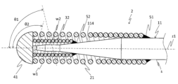
- Second Embodiment Fig. 3 is a schematic cross-sectional view showing the second embodiment.
- the guidewire 2 is generally composed of a core shaft 11, an outer coil body 21, an inner coil body 32, a distal end fixing portion 41, and proximal end fixing portions 51 and 52.
- the guidewire 2 differs from the first embodiment in that it further includes an inner coil body 32.
- the usage of the guidewire 2 is also the same as that of the first embodiment.
- the inner coil body 32 is a helical member that covers at least a portion of the tip of the core shaft 11, is disposed inside the outer coil body 21, and is formed by winding the wire w2 at a constant pitch.
- the wire w2 can be, for example, one or more solid wires, one or more twisted wires, or a combination of these.
- the material that can be used to form the inner coil body 32 is, for example, stainless steel such as SUS316; superelastic alloys such as Ni-Ti alloys; radiopaque metals such as platinum and tungsten; etc.
- the inner coil body 32 can have, for example, a tip end fixed integrally to the core shaft 11 and the outer coil body 21 at the tip fixing portion 41, and a base end fixed to any outer peripheral surface s of the core shaft 11.
- the inner coil body 32 has a tip end fixed at the tip fixing portion 41, and a base end fixed to the outer peripheral surface s of the second tapered portion 114 of the core shaft 11.
- the method of fixing the inner coil body 32 at the tip fixing portion 41 and the base end fixing portion 52 can be, for example, the same method as the fixing method at the tip fixing portion 41 and the base end fixing portion 51 of the outer coil body 21 described above, respectively.
- the winding direction of the wire w1 in the outer coil body 21 and the winding direction of the wire w2 in the inner coil body 32 may be opposite to each other, and the inclination angle ⁇ 1 of the wire w1 in the outer coil body 21 relative to the longitudinal axis z1 of the core shaft 11 may be different from the inclination angle ⁇ 2 of the wire w2 in the inner coil body 32 relative to the longitudinal axis z1 of the core shaft 11 (see Figure 3).
- the outer coil body 21 and the inner coil body 32 may be configured such that one of them is S-twisted and the other is Z-twisted, and the winding angle ⁇ 1 of the outer coil body 21 relative to the tip direction of the long axis z1 of the core shaft 11 and the winding angle ⁇ 2 of the inner coil body 32 relative to the tip direction of the long axis z1 of the core shaft 11 are different from each other.
- This makes it possible to more effectively prevent the strands of one coil body (e.g., the outer coil body 21) from entering the gaps between adjacent strands of the other coil body (e.g., the inner coil body 32).
- the guidewire 2 (medical device) is equipped with the inner coil body 32, which makes it possible to prevent the wire w1 that constitutes the outer coil body 21 from shifting in the radial direction.
- a guidewire 1 (medical device) was described in which the outer coil body 21 has a loosely wound portion 21A and a tightly wound portion 21B.
- the outer coil body 21 may be composed of only the loosely wound portion 21A without having the tightly wound portion 21B.
- the guidewires 1 and 2 are described in which the sparsely wound portion 21A is located at the tip end of the outer coil body 21.
- the sparsely wound portion 21A may be located midway in the longitudinal direction of the outer coil body or at the base end.
- the guidewires 1 and 2 are described in which the open coil portion 21A is provided at only one location on the outer coil body 21.
- the open coil portion 21A may be provided at two or more independent locations on the outer coil body.
- the guidewires 1 and 2 are described in which the core shaft 11 is configured in the following order from the tip: first columnar section 111, first tapered section 112, second columnar section 113, second tapered section 114, and third columnar section 115.
- the shape of the core shaft is not particularly limited.
- the core shaft does not have to have a tapered section, and may be configured only with a tapered section.
- the specifications of the medical device (guidewire) to be evaluated are shown in Table 1. Other specifications are as follows.
- the tip of the open coil portion in each sample is located at the tip of the outer coil body, and the length of the open coil portion in Table 1 indicates the length from the tip to the base end of the open coil portion.
- FIG. 4A(a) the guidewire to be tested was inserted from one opening 91a of a transparent silicone tube 91 with an inner diameter of 1.25 mm, and the tip of the guidewire was fixed to the silicone tube 91 via the hole 91b.
- FIG. 4A(b) the guidewire was twisted three times in the circumferential direction with respect to the silicone tube 91.
- FIG. 4B is an external photograph showing an example of a guidewire after being twisted three times in the circumferential direction.
- the fixation of the tip of the guidewire was released and removed from the silicone tube 91.
- the guidewire was disassembled to remove the outer coil body, and the angle (bending angle ⁇ 3) at which the tip of the outer coil body (21) bends with respect to the major axis z2 of the outer coil body (21) (the same as the longitudinal axis of the outer coil body before the test) was measured as shown in FIG. 5.
- the bending angle ⁇ 3 when the bending angle ⁇ 3 is 180 degrees or less, the ability to suppress the formation of a habit is evaluated as good, and when the bending angle ⁇ 3 is greater than 180 degrees, the ability to suppress the formation of a habit is evaluated as poor. In addition, when the bending angle ⁇ 3 is 90 degrees or less, the ability to suppress the formation of a habit is evaluated as even better, and when the bending angle ⁇ 3 is 45 degrees or less, the ability to suppress the formation of a habit is evaluated as best.
- the effective diameter D of the outer coil body 21/strand diameter d of the outer coil body 21 is preferably 4.5 or more and 5.5 or less.
- the effective diameter D of the outer coil body 21/strand diameter d of the outer coil body 21 is preferably 4.5 or more and 5 or less. This is because a smaller effective diameter D makes it easier to apply to guidewires with a small maximum outer diameter. It is also preferable that the effective diameter D of the outer coil body 21/strand diameter d of the outer coil body 21 is 5 or more and 5.5 or less. This is because the bending angle is suppressed.
Landscapes
- Health & Medical Sciences (AREA)
- Life Sciences & Earth Sciences (AREA)
- Biophysics (AREA)
- Pulmonology (AREA)
- Engineering & Computer Science (AREA)
- Anesthesiology (AREA)
- Biomedical Technology (AREA)
- Heart & Thoracic Surgery (AREA)
- Hematology (AREA)
- Animal Behavior & Ethology (AREA)
- General Health & Medical Sciences (AREA)
- Public Health (AREA)
- Veterinary Medicine (AREA)
- Media Introduction/Drainage Providing Device (AREA)
Abstract
Description
(1)コアシャフトと、
前記コアシャフトの先端部の少なくとも一部を覆うように設けられ、素線を巻回することで形成された外側コイル体と、
前記コアシャフトの先端と前記外側コイル体の先端とが互いに固着した先端固着部と、を備えている医療デバイスであって、
前記外側コイル体は、前記コアシャフトの長軸方向に沿って隣り合う素線の部分に隙間を有する疎巻部を具備し、
前記外側コイル体の疎巻部は、下記式(1)および(2)を満たすことを特徴とする医療デバイス、
3.5≦D/d≦6.5 ・・・(1)
1<Pa≦3 ・・・(2)
(前記式(1)中、Dは前記外側コイル体の有効径を、dは前記外側コイル体の素線径をそれぞれ示す。前記式(2)中、Paは前記外側コイル体における素線のピッチの代表値を示す。)
(2)前記ピッチの代表値Paが1<Pa≦2を満たす前記(1)に記載の医療デバイス、
(3)前記外側コイル体の有効径Dおよび前記外側コイル体の素線径dは、4.5≦D/d≦5を満たす前記(2)に記載の医療デバイス、
(4)前記外側コイル体の有効径Dおよび前記外側コイル体の素線径dは、5≦D/d≦5.5を満たす前記(2)に記載の医療デバイス、
(5)前記ピッチの代表値Paが1<Pa≦1.5を満たす前記(2)から(4)のいずれか1項に記載の医療デバイス、
(6)前記ピッチの代表値Paが1<Pa≦1.1を満たす前記(5)に記載の医療デバイス、
(7)前記疎巻部の先端は前記外側コイル体の先端に位置し、前記疎巻部の基端は前記外側コイル体の先端から基端側に向かって10mm~30mmの部位に位置する前記(1)から(6)のいずれか1項に記載の医療デバイス、
(8)前記コアシャフトの先端部の少なくとも一部を覆うと共に、前記外側コイル体の内側に配置され、素線を一定のピッチで巻回することで形成された内側コイル体をさらに備えている前記(1)から(7)のいずれか1項に記載の医療デバイス、
(9)前記外側コイル体における素線の巻回方向と前記内側コイル体における素線の巻回方向とが互いに逆向きであり、かつ前記コアシャフトの長軸に対する前記外側コイル体における素線の傾斜角度と、前記コアシャフトの長軸に対する前記内側コイル体における素線の傾斜角度とが異なる前記(8)に記載の医療デバイス、
(10)前記先端固着部を固定しながら前記コアシャフトの基端を周方向に3周捻った後に前記先端固着部の固定を解除し、外側コイル体を取り出して測定した、長軸先端方向に対する当該外側コイル体の先端部の屈曲角度が、180度以下である前記(1)から(9)のいずれか1項に記載の医療デバイス、
(11)前記屈曲角度が90度以下である前記(10)に記載の医療デバイス、並びに
(12)前記屈曲角度が45度以下である前記(11)に記載の医療デバイス、である。
図1,図2は、第1の実施形態を示す概略的断面図である。図1,図2に示すように、ガイドワイヤ1は、概略的に、コアシャフト11と、外側コイル体21と、先端固着部41と、基端固着部51とにより構成されている。
3.5≦D/d≦6.5 ・・・(1)
1<Pa≦3 ・・・(2)
ただし、式(1)中、Dは外側コイル体21の有効径を、dは外側コイル体21の素線径をそれぞれ示す。上記式(2)中、Paは外側コイル体21における素線w1のピッチの代表値を示している。
図3は、第2の実施形態を示す概略的断面図である。図3に示すように、ガイドワイヤ2は、概略的に、コアシャフト11と、外側コイル体21と、内側コイル体32と、先端固着部41と、基端固着部51、52とにより構成されている。ガイドワイヤ2は、内側コイル体32をさらに備えている点で、第1の実施形態と異なっている。なお、以下に示す内側コイル体32の構成以外の構成は第1の実施形態のものと同様であるので、同一部分には同一符号を付してその詳細な説明を省略する。また、ガイドワイヤ2の使用態様は、第1の実施形態のものと同様である。
評価に供する医療デバイス(ガイドワイヤ)の仕様を表1に示す。また、その他の仕様は以下の通りである。なお、各サンプルにおけるピッチの代表値Paは、Pa=(Pmin+Pmax)/2dの値を用いたものである。ただし、Pminは外側コイル体のピッチのうちの最小のピッチを、Pmaxは外側コイル体のピッチのうちの最大のピッチを、dは外側コイル体の素線径をそれぞれ表している。また、各サンプルにおける疎巻部の先端は、外側コイル体の先端に位置し、表1中の疎巻部の長さは、疎巻部の先端から基端までの長さを示している。
・材質 :Pt-Ni合金
・コイル有効径D :0.36mm-(d/2×2)
・コイル外径 :0.36mm
・素線径d :表1に記載
・ピッチの代表値Pa :表1に記載
・疎巻部の長さ :表1に記載
[内側コイル体]
・材質 :ステンレス鋼
・コイル外径 :0.2mm
・素線径 :0.025mm
表1に示した各ガイドワイヤを用い、癖付き抑制性および位置ズレ抑制性を下記方法に従い評価した。その結果を表1に合わせて示す。
試験(癖付き試験)に供するガイドワイヤの先端固着部を固定しながら、コアシャフトの基端を周方向に3周捻った後、先端固着部の固定を解除し、外側コイル体を取り出して測定した。この際、長軸先端方向に対する当該外側コイル体の先端部の曲がり度合(屈曲角度)を測定し、この測定値を指標として癖付き抑制性を評価した。
上述した癖付き抑制性の評価後の外側コイル体を用い、顕微鏡により倍率20倍の実体像を観察した。その際、外側コイル体1本当たりの位置ずれ箇所(明らかに位置ズレしていると認められる箇所)の数をカウントし、その数を指標として位置ズレ抑制性を評価した。

11 コアシャフト
21 外側コイル体
21A 疎巻部
32 内側コイル体
41 先端固着部
D 外側コイル体の有効径
d 外側コイル体の素線径
Pa ピッチの代表値
θ1,θ2 傾斜角度
θ3 屈曲角度
z2 外側コイル体の長軸
Claims (12)
- コアシャフトと、
前記コアシャフトの先端部の少なくとも一部を覆うように設けられ、素線を巻回することで形成された外側コイル体と、
前記コアシャフトの先端と前記外側コイル体の先端とが互いに固着した先端固着部と、を備えている医療デバイスであって、
前記外側コイル体は、前記コアシャフトの長軸方向に沿って隣り合う素線の部分に隙間を有する疎巻部を具備し、
前記外側コイル体の疎巻部は、下記式(1)および(2)を満たすことを特徴とする医療デバイス。
3.5≦D/d≦6.5 ・・・(1)
1<Pa≦3 ・・・(2)
(前記式(1)中、Dは前記外側コイル体の有効径を、dは前記外側コイル体の素線径をそれぞれ示す。前記式(2)中、Paは前記外側コイル体における素線のピッチの代表値を示す。) - 前記ピッチの代表値Paが1<Pa≦2を満たす請求項1に記載の医療デバイス。
- 前記外側コイル体の有効径Dおよび前記外側コイル体の素線径dは、4.5≦D/d≦5を満たす請求項2に記載の医療デバイス。
- 前記外側コイル体の有効径Dおよび前記外側コイル体の素線径dは、5≦D/d≦5.5を満たす請求項2に記載の医療デバイス。
- 前記ピッチの代表値Paが1<Pa≦1.5を満たす請求項2から請求項4のいずれか1項に記載の医療デバイス。
- 前記ピッチの代表値Paが1<Pa≦1.1を満たす請求項5に記載の医療デバイス。
- 前記疎巻部の先端は前記外側コイル体の先端に位置し、前記疎巻部の基端は前記外側コイル体の先端から基端側に向かって10mm~30mmの部位に位置する請求項1から請求項6のいずれか1項に記載の医療デバイス。
- 前記コアシャフトの先端部の少なくとも一部を覆うと共に、前記外側コイル体の内側に配置され、素線を一定のピッチで巻回することで形成された内側コイル体をさらに備えている請求項1から請求項7のいずれか1項に記載の医療デバイス。
- 前記外側コイル体における素線の巻回方向と前記内側コイル体における素線の巻回方向とが互いに逆向きであり、かつ前記コアシャフトの長軸に対する前記外側コイル体における素線の傾斜角度と、前記コアシャフトの長軸に対する前記内側コイル体における素線の傾斜角度とが異なる請求項8に記載の医療デバイス。
- 前記先端固着部を固定しながら前記コアシャフトの基端を周方向に3周捻った後に前記先端固着部の固定を解除し、外側コイル体を取り出して測定した、長軸先端方向に対する当該外側コイル体の先端部の屈曲角度が、180度以下である請求項1から請求項9のいずれか1項に記載の医療デバイス。
- 前記屈曲角度が90度以下である請求項10に記載の医療デバイス。
- 前記屈曲角度が45度以下である請求項11に記載の医療デバイス。
Priority Applications (3)
| Application Number | Priority Date | Filing Date | Title |
|---|---|---|---|
| EP24823191.2A EP4729106A1 (en) | 2023-06-16 | 2024-05-22 | Medical device |
| CN202480039820.3A CN121358518A (zh) | 2023-06-16 | 2024-05-22 | 医疗设备 |
| US19/421,739 US20260115428A1 (en) | 2023-06-16 | 2025-12-16 | Medical device |
Applications Claiming Priority (2)
| Application Number | Priority Date | Filing Date | Title |
|---|---|---|---|
| JP2023099120A JP2024179866A (ja) | 2023-06-16 | 2023-06-16 | 医療デバイス |
| JP2023-099120 | 2023-06-16 |
Related Child Applications (1)
| Application Number | Title | Priority Date | Filing Date |
|---|---|---|---|
| US19/421,739 Continuation US20260115428A1 (en) | 2023-06-16 | 2025-12-16 | Medical device |
Publications (1)
| Publication Number | Publication Date |
|---|---|
| WO2024257569A1 true WO2024257569A1 (ja) | 2024-12-19 |
Family
ID=93851764
Family Applications (1)
| Application Number | Title | Priority Date | Filing Date |
|---|---|---|---|
| PCT/JP2024/018830 Ceased WO2024257569A1 (ja) | 2023-06-16 | 2024-05-22 | 医療デバイス |
Country Status (5)
| Country | Link |
|---|---|
| US (1) | US20260115428A1 (ja) |
| EP (1) | EP4729106A1 (ja) |
| JP (1) | JP2024179866A (ja) |
| CN (1) | CN121358518A (ja) |
| WO (1) | WO2024257569A1 (ja) |
Citations (4)
| Publication number | Priority date | Publication date | Assignee | Title |
|---|---|---|---|---|
| JPH10146390A (ja) | 1997-12-05 | 1998-06-02 | Terumo Corp | ガイドワイヤー |
| JP2009511184A (ja) * | 2005-10-11 | 2009-03-19 | ボストン サイエンティフィック リミテッド | 医療器具コイル |
| JP2016002210A (ja) * | 2014-06-16 | 2016-01-12 | 株式会社エフエムディ | 医療用ガイドワイヤ |
| JP2017164200A (ja) * | 2016-03-15 | 2017-09-21 | テルモ株式会社 | ガイドワイヤ |
-
2023
- 2023-06-16 JP JP2023099120A patent/JP2024179866A/ja active Pending
-
2024
- 2024-05-22 CN CN202480039820.3A patent/CN121358518A/zh active Pending
- 2024-05-22 EP EP24823191.2A patent/EP4729106A1/en active Pending
- 2024-05-22 WO PCT/JP2024/018830 patent/WO2024257569A1/ja not_active Ceased
-
2025
- 2025-12-16 US US19/421,739 patent/US20260115428A1/en active Pending
Patent Citations (4)
| Publication number | Priority date | Publication date | Assignee | Title |
|---|---|---|---|---|
| JPH10146390A (ja) | 1997-12-05 | 1998-06-02 | Terumo Corp | ガイドワイヤー |
| JP2009511184A (ja) * | 2005-10-11 | 2009-03-19 | ボストン サイエンティフィック リミテッド | 医療器具コイル |
| JP2016002210A (ja) * | 2014-06-16 | 2016-01-12 | 株式会社エフエムディ | 医療用ガイドワイヤ |
| JP2017164200A (ja) * | 2016-03-15 | 2017-09-21 | テルモ株式会社 | ガイドワイヤ |
Also Published As
| Publication number | Publication date |
|---|---|
| EP4729106A1 (en) | 2026-04-22 |
| CN121358518A (zh) | 2026-01-16 |
| JP2024179866A (ja) | 2024-12-26 |
| US20260115428A1 (en) | 2026-04-30 |
Similar Documents
| Publication | Publication Date | Title |
|---|---|---|
| EP2338555B1 (en) | Guidewire | |
| EP2338556B1 (en) | Guidewire | |
| EP2361652B1 (en) | Guidewire | |
| EP2962718A1 (en) | Guidewire | |
| EP2881136B1 (en) | Guidewire | |
| JP7050175B2 (ja) | 医療機器 | |
| JP7051032B1 (ja) | ガイドワイヤ | |
| JP2024179866A (ja) | 医療デバイス | |
| JP2013176488A (ja) | ガイドワイヤ | |
| JP7509922B2 (ja) | ガイドワイヤ | |
| JP7532573B2 (ja) | ガイドワイヤ | |
| JP7689449B2 (ja) | ガイドワイヤ | |
| JP7545339B2 (ja) | 多層コイル | |
| JP2015070895A (ja) | シャフト及びそのシャフトを用いたガイドワイヤ | |
| EP4620505A1 (en) | Guide wire | |
| JP7353043B2 (ja) | ガイドワイヤ | |
| JP2017164200A (ja) | ガイドワイヤ | |
| JP7290451B2 (ja) | ガイドワイヤ | |
| JP2024062131A (ja) | 医療デバイス | |
| WO2024116318A1 (ja) | 医療デバイス | |
| JP7021350B2 (ja) | ガイドワイヤ | |
| JP2024048505A (ja) | コイル体 | |
| WO2024210114A1 (ja) | ガイドワイヤ | |
| JP2024126330A (ja) | 医療デバイス |
Legal Events
| Date | Code | Title | Description |
|---|---|---|---|
| 121 | Ep: the epo has been informed by wipo that ep was designated in this application |
Ref document number: 24823191 Country of ref document: EP Kind code of ref document: A1 |
|
| WWE | Wipo information: entry into national phase |
Ref document number: 2024823191 Country of ref document: EP |
|
| NENP | Non-entry into the national phase |
Ref country code: DE |
|
| ENP | Entry into the national phase |
Ref document number: 2024823191 Country of ref document: EP Effective date: 20260116 |
|
| ENP | Entry into the national phase |
Ref document number: 2024823191 Country of ref document: EP Effective date: 20260116 |
|
| ENP | Entry into the national phase |
Ref document number: 2024823191 Country of ref document: EP Effective date: 20260116 |
|
| ENP | Entry into the national phase |
Ref document number: 2024823191 Country of ref document: EP Effective date: 20260116 |
|
| WWP | Wipo information: published in national office |
Ref document number: 2024823191 Country of ref document: EP |