WO2024257534A1 - 地図処理装置及び地図処理方法 - Google Patents
地図処理装置及び地図処理方法 Download PDFInfo
- Publication number
- WO2024257534A1 WO2024257534A1 PCT/JP2024/017798 JP2024017798W WO2024257534A1 WO 2024257534 A1 WO2024257534 A1 WO 2024257534A1 JP 2024017798 W JP2024017798 W JP 2024017798W WO 2024257534 A1 WO2024257534 A1 WO 2024257534A1
- Authority
- WO
- WIPO (PCT)
- Prior art keywords
- lane
- route
- data
- map
- map data
- Prior art date
- Legal status (The legal status is an assumption and is not a legal conclusion. Google has not performed a legal analysis and makes no representation as to the accuracy of the status listed.)
- Ceased
Links
Images




Classifications
-
- G—PHYSICS
- G01—MEASURING; TESTING
- G01C—MEASURING DISTANCES, LEVELS OR BEARINGS; SURVEYING; NAVIGATION; GYROSCOPIC INSTRUMENTS; PHOTOGRAMMETRY OR VIDEOGRAMMETRY
- G01C21/00—Navigation; Navigational instruments not provided for in groups G01C1/00 - G01C19/00
- G01C21/26—Navigation; Navigational instruments not provided for in groups G01C1/00 - G01C19/00 specially adapted for navigation in a road network
- G01C21/34—Route searching; Route guidance
- G01C21/3407—Route searching; Route guidance specially adapted for specific applications
-
- G—PHYSICS
- G01—MEASURING; TESTING
- G01C—MEASURING DISTANCES, LEVELS OR BEARINGS; SURVEYING; NAVIGATION; GYROSCOPIC INSTRUMENTS; PHOTOGRAMMETRY OR VIDEOGRAMMETRY
- G01C21/00—Navigation; Navigational instruments not provided for in groups G01C1/00 - G01C19/00
- G01C21/26—Navigation; Navigational instruments not provided for in groups G01C1/00 - G01C19/00 specially adapted for navigation in a road network
-
- G—PHYSICS
- G01—MEASURING; TESTING
- G01C—MEASURING DISTANCES, LEVELS OR BEARINGS; SURVEYING; NAVIGATION; GYROSCOPIC INSTRUMENTS; PHOTOGRAMMETRY OR VIDEOGRAMMETRY
- G01C21/00—Navigation; Navigational instruments not provided for in groups G01C1/00 - G01C19/00
- G01C21/26—Navigation; Navigational instruments not provided for in groups G01C1/00 - G01C19/00 specially adapted for navigation in a road network
- G01C21/34—Route searching; Route guidance
-
- G—PHYSICS
- G01—MEASURING; TESTING
- G01C—MEASURING DISTANCES, LEVELS OR BEARINGS; SURVEYING; NAVIGATION; GYROSCOPIC INSTRUMENTS; PHOTOGRAMMETRY OR VIDEOGRAMMETRY
- G01C21/00—Navigation; Navigational instruments not provided for in groups G01C1/00 - G01C19/00
- G01C21/38—Electronic maps specially adapted for navigation; Updating thereof
- G01C21/3885—Transmission of map data to client devices; Reception of map data by client devices
- G01C21/3889—Transmission of selected map data, e.g. depending on route
-
- G—PHYSICS
- G16—INFORMATION AND COMMUNICATION TECHNOLOGY [ICT] SPECIALLY ADAPTED FOR SPECIFIC APPLICATION FIELDS
- G16Y—INFORMATION AND COMMUNICATION TECHNOLOGY SPECIALLY ADAPTED FOR THE INTERNET OF THINGS [IoT]
- G16Y10/00—Economic sectors
- G16Y10/40—Transportation
-
- G—PHYSICS
- G16—INFORMATION AND COMMUNICATION TECHNOLOGY [ICT] SPECIALLY ADAPTED FOR SPECIFIC APPLICATION FIELDS
- G16Y—INFORMATION AND COMMUNICATION TECHNOLOGY SPECIALLY ADAPTED FOR THE INTERNET OF THINGS [IoT]
- G16Y20/00—Information sensed or collected by the things
- G16Y20/20—Information sensed or collected by the things relating to the thing itself
-
- G—PHYSICS
- G16—INFORMATION AND COMMUNICATION TECHNOLOGY [ICT] SPECIALLY ADAPTED FOR SPECIFIC APPLICATION FIELDS
- G16Y—INFORMATION AND COMMUNICATION TECHNOLOGY SPECIALLY ADAPTED FOR THE INTERNET OF THINGS [IoT]
- G16Y40/00—IoT characterised by the purpose of the information processing
- G16Y40/60—Positioning; Navigation
-
- G—PHYSICS
- G01—MEASURING; TESTING
- G01C—MEASURING DISTANCES, LEVELS OR BEARINGS; SURVEYING; NAVIGATION; GYROSCOPIC INSTRUMENTS; PHOTOGRAMMETRY OR VIDEOGRAMMETRY
- G01C21/00—Navigation; Navigational instruments not provided for in groups G01C1/00 - G01C19/00
- G01C21/26—Navigation; Navigational instruments not provided for in groups G01C1/00 - G01C19/00 specially adapted for navigation in a road network
- G01C21/34—Route searching; Route guidance
- G01C21/3407—Route searching; Route guidance specially adapted for specific applications
- G01C21/3415—Dynamic re-routing, e.g. recalculating the route when the user deviates from calculated route or after detecting real-time traffic data or accidents
-
- G—PHYSICS
- G01—MEASURING; TESTING
- G01C—MEASURING DISTANCES, LEVELS OR BEARINGS; SURVEYING; NAVIGATION; GYROSCOPIC INSTRUMENTS; PHOTOGRAMMETRY OR VIDEOGRAMMETRY
- G01C21/00—Navigation; Navigational instruments not provided for in groups G01C1/00 - G01C19/00
- G01C21/26—Navigation; Navigational instruments not provided for in groups G01C1/00 - G01C19/00 specially adapted for navigation in a road network
- G01C21/34—Route searching; Route guidance
- G01C21/36—Input/output arrangements for on-board computers
- G01C21/3602—Input other than that of destination using image analysis, e.g. detection of road signs, lanes, buildings, real preceding vehicles using a camera
-
- G—PHYSICS
- G01—MEASURING; TESTING
- G01C—MEASURING DISTANCES, LEVELS OR BEARINGS; SURVEYING; NAVIGATION; GYROSCOPIC INSTRUMENTS; PHOTOGRAMMETRY OR VIDEOGRAMMETRY
- G01C21/00—Navigation; Navigational instruments not provided for in groups G01C1/00 - G01C19/00
- G01C21/26—Navigation; Navigational instruments not provided for in groups G01C1/00 - G01C19/00 specially adapted for navigation in a road network
- G01C21/34—Route searching; Route guidance
- G01C21/36—Input/output arrangements for on-board computers
- G01C21/3626—Details of the output of route guidance instructions
- G01C21/3658—Lane guidance
-
- G—PHYSICS
- G01—MEASURING; TESTING
- G01C—MEASURING DISTANCES, LEVELS OR BEARINGS; SURVEYING; NAVIGATION; GYROSCOPIC INSTRUMENTS; PHOTOGRAMMETRY OR VIDEOGRAMMETRY
- G01C21/00—Navigation; Navigational instruments not provided for in groups G01C1/00 - G01C19/00
- G01C21/38—Electronic maps specially adapted for navigation; Updating thereof
- G01C21/3804—Creation or updating of map data
- G01C21/3807—Creation or updating of map data characterised by the type of data
- G01C21/3815—Road data
- G01C21/3819—Road shape data, e.g. outline of a route
-
- G—PHYSICS
- G01—MEASURING; TESTING
- G01C—MEASURING DISTANCES, LEVELS OR BEARINGS; SURVEYING; NAVIGATION; GYROSCOPIC INSTRUMENTS; PHOTOGRAMMETRY OR VIDEOGRAMMETRY
- G01C21/00—Navigation; Navigational instruments not provided for in groups G01C1/00 - G01C19/00
- G01C21/38—Electronic maps specially adapted for navigation; Updating thereof
- G01C21/3804—Creation or updating of map data
- G01C21/3833—Creation or updating of map data characterised by the source of data
- G01C21/3848—Data obtained from both position sensors and additional sensors
-
- G—PHYSICS
- G01—MEASURING; TESTING
- G01C—MEASURING DISTANCES, LEVELS OR BEARINGS; SURVEYING; NAVIGATION; GYROSCOPIC INSTRUMENTS; PHOTOGRAMMETRY OR VIDEOGRAMMETRY
- G01C21/00—Navigation; Navigational instruments not provided for in groups G01C1/00 - G01C19/00
- G01C21/38—Electronic maps specially adapted for navigation; Updating thereof
- G01C21/3863—Structures of map data
- G01C21/387—Organisation of map data, e.g. version management or database structures
- G01C21/3881—Tile-based structures
-
- G—PHYSICS
- G01—MEASURING; TESTING
- G01C—MEASURING DISTANCES, LEVELS OR BEARINGS; SURVEYING; NAVIGATION; GYROSCOPIC INSTRUMENTS; PHOTOGRAMMETRY OR VIDEOGRAMMETRY
- G01C21/00—Navigation; Navigational instruments not provided for in groups G01C1/00 - G01C19/00
- G01C21/38—Electronic maps specially adapted for navigation; Updating thereof
- G01C21/3885—Transmission of map data to client devices; Reception of map data by client devices
- G01C21/3896—Transmission of map data from central databases
Definitions
- the present invention relates to a map processing device and a map processing method.
- Patent Document 1 discloses a technology for selecting map data tiles of an area including a first route and an area including a secondary route (such as a return route) selected based on the first route from the entire available map data, and extracting the map data.
- map data pre-reading technology disclosed in Patent Document 1 map data of a secondary route is pre-read based on the first route, but the amount of accessed map data is adjusted based on the priority of the secondary route.
- map processing devices that enable driving assistance at the lane level of roads (hereinafter simply referred to as "lanes"), which is necessary for the automated driving of cars that has been developed in recent years, use map data with a higher level of detail than conventional car navigation systems that can be used for driving assistance at the road level. Therefore, map processing devices that handle such high-detail map data also require a large amount of map data to be stored in the device, and the above-mentioned demand is great.
- the above-mentioned Patent Document 1 discloses a technology for predicting another route (secondary route) that is assumed based on the vehicle's position and route, but on expressways, secondary routes tend to be long distances. Therefore, even if the technology disclosed in the above-mentioned Patent Document 1 is applied to a map processing device that handles high-detail map data, it is difficult to predict all map data of secondary routes required for driving assistance.
- the present invention has been made to meet the above demand.
- the object of the present invention is to provide a technology for a map processing device used for vehicle driving assistance that can achieve both a reduction in the storage capacity required to hold map data within the device and the maintenance of device performance.
- the map processing device of the present invention includes a map data pre-reading unit capable of acquiring multiple types of map data.
- the multiple types of map data include lane connection data indicating connection information between lane sections in the extension direction of the lanes, and lane group connection data indicating connection information between lane group sections in the extension direction of a lane group made up of one or more lanes.
- the map data pre-reading unit acquires a type of map data according to the conditions of the specific point.
- the map processing method of the present invention includes the map data pre-reading unit of the map processing device of the present invention acquiring a type of map data according to the conditions of the specified location when acquiring map data of the specified location from multiple types of map data.
- the present invention configured as described above, makes it possible to reduce the storage capacity for storing map data within a map processing device used for vehicle driving assistance while maintaining the performance of the device.
- FIG. 1 is a schematic diagram showing the configuration of an in-vehicle system including a map processing device according to an embodiment of the present invention.
- FIG. 2 is a functional block diagram of a map processing device according to an embodiment of the present invention.
- FIG. 3 is a diagram showing the relationship between various map data stored in the storage unit of the map processing device according to one embodiment of the present invention and various applications that use the various map data.
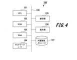
- FIG. 4 is a diagram showing the hardware configuration of a map processing device according to an embodiment of the present invention.
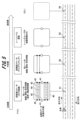
- FIG. 5 is a schematic diagram showing the relationship between various map data pre-read in a map processing device according to an embodiment of the present invention and the distance from the vehicle position to a pre-read target point.
- FIG. 1 is a schematic diagram showing the configuration of an in-vehicle system including a map processing device according to an embodiment of the present invention.
- FIG. 2 is a functional block diagram of a map processing device according to an embodiment of the present invention.
- FIG. 3 is a
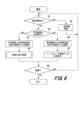
- FIG. 6 is a flowchart showing the procedure of pre-reading various map data by the map processing device according to one embodiment of the present invention.
- FIG. 7 is a flowchart showing the procedure of a pre-reading process of various map data performed by the map processing device according to an embodiment of the present invention.
- FIG. 8 is a diagram for explaining an overview of a first route change operation example when a route deviation occurs, which is performed by a map processing device according to an embodiment of the present invention.
- FIG. 9 is a diagram showing an operational flow of a first route change operation example when a route deviation occurs, by a map processing device according to an embodiment of the present invention.
- FIG. 10 is a diagram for explaining an overview of a second route change operation example when a route deviation occurs, which is performed by the map processing device according to one embodiment of the present invention.
- FIG. 11 is a diagram showing an operational flow of a second route changing operation when a route deviation occurs, performed by the map processing device according to an embodiment of the present invention.
- map processing device and a map processing method (map data read-ahead method) according to one embodiment of the present invention will be specifically described with reference to the drawings.
- vehicle control calculation device e.g., MPU (Map Positioning Unit), etc.
- ECU Electronic Control Unit
- AD Autonomous Driving
- FIG. 1 is a schematic diagram of an in-vehicle system including a map processing device according to an embodiment of the present invention, in which only components related to various processes performed by the map processing device are shown.
- the vehicle-mounted system 1 of the vehicle equipped with an automatic driving function includes a map processing device 2, a car navigation system 3 (hereinafter referred to as "car navigation 3"), and an automatic driving control device 4, and each component is connected to each other within the vehicle-mounted system 1.
- the map processing device 2 is also connected to a map distribution server 5 provided externally, such as a cloud, via a communication network 6.
- the map distribution server 5 stores various map data with high detail at the lane level required for autonomous driving assistance of the vehicle (for example, lane connection data, lane attribute data, lane boundary data, etc., described below; hereinafter, referred to as "high-precision map data").
- the map processing device 2 obtains various high-precision map data of the surroundings of the vehicle on demand from the map distribution server 5.
- the car navigation system 3 is connected via a communication network to a map distribution server for the car navigation system that is provided externally, for example, in the cloud, and obtains various map data of the road level of the surroundings of the vehicle on demand from the map distribution server for the car navigation system.
- the map processing device 2 has a function of acquiring in advance (hereinafter referred to as "pre-reading") various high-precision map data of the recommended route (hereinafter referred to as "planned driving route”) to the destination required for the autonomous driving assistance of the vehicle and its surrounding routes from the map distribution server 5.
- pre-reading various high-precision map data of the recommended route
- planned driving route the recommended route
- the "surrounding routes of the planned driving route” here means a route that can branch off from the planned driving route.
- the map processing device 2 searches for the planned driving route using the various high-precision map data that have been pre-read, and outputs information on the planned driving route determined by the search process to the autonomous driving control device 4.
- the map processing device 2 when the vehicle deviates from the planned driving route, the map processing device 2 also searches for and determines a new planned driving route using the various high-precision map data that have been pre-read. Note that the internal configuration and processing contents of the map processing device 2 will be described later with reference to the drawings.
- the car navigation system 3 searches for a recommended route to the destination using various road-level map data of the area around the vehicle obtained from a map distribution server for car navigation systems, and sets the recommended route obtained by the search process as the planned driving route.
- the car navigation system 3 outputs various information, such as the planned driving route, destination, and route search conditions set in the car navigation system 3, to the map processing device 2.
- the automatic driving control device 4 performs automatic driving control of the vehicle using information on the planned driving route to the destination set by the map processing device 2 or the car navigation system 3.
- FIG. 2 is a configuration diagram of functional blocks of a map processing device 2 according to an embodiment of the present invention. Fig. 2 shows only components related to the process of pre-reading various high-precision geographic data by the map processing device 2 and the process of searching for and determining a planned driving route to a destination.
- the map processing device 2 includes a control unit 10, a memory unit 11, a sensor unit 12, a first communication unit 13, a second communication unit 14, and a third communication unit 15.
- the control unit 10 is connected to the memory unit 11, the sensor unit 12, the first communication unit 13, and the second communication unit 14, and the memory unit 11 is connected to the third communication unit 15.
- the control unit 10 searches for a recommended route to the destination at the lane level using various data (information) acquired from the memory unit 11, the sensor unit 12, and the first communication unit 13, and outputs information on the planned driving route obtained as a result of the search to the automatic driving control device 4 via the second communication unit 14.
- the control unit 10 also searches for and determines a new planned driving route.
- the internal configuration of the control unit 10 will be described later.
- the storage unit 11 is connected to an external map distribution server 5 via a third communication unit.
- the storage unit 11 stores various high-precision map data that enables lane-level automated driving assistance distributed from the map distribution server 5.
- the map distribution server 5 stores various high-precision map data that enables lane-level automated driving assistance not only for expressways but also for general roads.
- the storage unit 11 also includes a lane connection and attribute data storage unit 31, a lane boundary data storage unit 32, a lane shape data storage unit 33, and a lane group connection data storage unit 34.
- the lane connection and attribute data storage unit 31 stores information (hereinafter referred to as "lane connection data") regarding the connection relationships between lane sections that are connected to each other via branching points (e.g., intersections, etc., hereinafter referred to as "nodes”) where the structure of the travel lane changes physically.
- lane connection data includes various information, such as connection information between lane sections (between nodes) in the extension direction of the lane, as well as information regarding the position coordinates of the nodes, lane identification information, travel direction, and information regarding whether the lane can be changed at the node.
- the lane connection and attribute data storage unit 31 also stores information relating to the attributes (properties and characteristics) of each lane between nodes (hereinafter referred to as "lane attribute data").
- the lane attribute data includes various information between nodes, such as lane type information, lane width, lane curvature, lane gradient type, and information indicating whether the lane is passable.
- the information indicating whether the lane is passable, which is included in the lane attribute data includes real-time or time-limited traffic information, such as congestion information and information on construction work.
- the lane boundary data storage unit 32 stores information about the boundaries between adjacent lanes in a direction perpendicular to the direction in which the lanes extend (hereinafter referred to as "lane boundary data").
- the lane boundary data includes information such as the type of boundary line between lanes (e.g., white line, orange line, etc.) and the pattern type of the boundary line.
- the lane shape data storage unit 33 stores information about the shape of each lane between nodes (hereinafter referred to as “lane shape data").
- the lane shape data includes separate data on the shape of the center line of each lane (hereinafter referred to as “lane center line shape data”) and data on the shape of the boundaries of each lane (hereinafter referred to as “lane boundary shape data"). Note that both the lane center line shape data and the lane boundary shape data are composed of coordinate point sequence data.
- connection information is used that aggregates multiple lanes existing between nodes into one group (hereinafter referred to as a "lane group").
- a lane group is also set for a driving route where the number of lane existing between nodes is one (for example, a general road in Figures 8 to 10 described below). That is, in this embodiment, a lane group is composed of one or more lanes.
- the lane group connection data storage unit 34 stores information regarding the connection between lane groups that are connected to each other via nodes (hereinafter referred to as "lane group connection data").
- the lane group connection data only needs to include the minimum connection information between lane groups, and in addition to the connection information between lane groups (between nodes) in the extension direction of the lane group, various information such as lane group identification information is included.
- the sensor unit 12 has various devices for recognizing structures and vehicles around the vehicle, the vehicle's position, the vehicle's driving conditions, etc.
- the sensor unit 12 includes various devices such as a camera (imaging device) capable of capturing images of the conditions around the vehicle, a GPS (Global Positioning System) module capable of measuring the vehicle's position at road level, and an acceleration sensor and angular velocity sensor capable of measuring the vehicle's driving conditions.
- the various information acquired by the sensor unit 12 is input to the control unit 10, which performs recognition processing of structures and vehicles around the vehicle and estimation processing of the vehicle's position based on this information.
- the first communication unit 13 is connected to the car navigation system 3.
- Various information set in the car navigation system 3, such as the planned driving route, destination, and route search conditions, is transmitted to the control unit 10 via the first communication unit 13.
- the second communication unit 14 is connected to the automatic driving control device 4.
- Information on the planned driving route to the destination determined by the control unit 10 is transmitted to the automatic driving control device 4 via the second communication unit 14.
- the third communication unit 15 is connected to an external map distribution server 5 via the communication network 6, receives various high-precision map data distributed from the map distribution server 5, and outputs the received various high-precision map data to the storage unit 11.
- the operations of the first communication unit 13 to the third communication unit 15 are controlled by the control unit 10.
- control unit 10 functionally includes a surrounding recognition unit 20, a self-position estimation unit 21, a candidate route search unit 22 (route search unit), a route selection unit 23 (route determination unit), a lane data pre-reading unit 24 (map data pre-reading unit), and a map access unit 25.
- the functional processing connections between the functional blocks are as follows:
- the surroundings recognition unit 20 is connected to the sensor unit 12, the self-position estimation unit 21, and the lane data read-ahead unit 24.
- the self-position estimation unit 21 is connected to the sensor unit 12, the candidate route search unit 22, and the lane data read-ahead unit 24.
- the candidate route search unit 22 is connected to the first communication unit 13, the route selection unit 23, and the lane data read-ahead unit 24.
- the route selection unit 23 is connected to the second communication unit 14 and the map access unit 25.
- the lane data read-ahead unit 24 is connected to the map access unit 25.
- the map access unit 25 is also connected to the lane connection and attribute data storage unit 31, the lane boundary data storage unit 32, the lane shape data storage unit 33, and the lane group connection data storage unit 34 in the storage unit 11.
- the surroundings recognition unit 20 recognizes the presence and position of structures and vehicles in the vicinity ahead of the vehicle based on an image of the surroundings ahead of the vehicle input from a camera (not shown) in the sensor unit 12 and various high-precision map data input from the lane data read-ahead unit 24. The surroundings recognition unit 20 then outputs the recognition results of structures and vehicles around the vehicle to the self-position estimation unit 21 and the lane data read-ahead unit 24.
- the self-position estimation unit 21 estimates the vehicle's position at the lane level based on the recognition results of structures and vehicles around the vehicle input from the surrounding recognition unit 20, various sensor information input from the sensor unit 12, and various high-precision map data input from the lane data read-ahead unit 24.
- two types of applications are installed as applications for estimating the vehicle position by the self-position estimation unit 21. Specifically, an application that estimates the vehicle position using an image of the surroundings in front of the vehicle and high-precision map data, and an application that estimates the vehicle position using high-precision map data are installed.
- the former application is referred to as a “high-precision locator (camera recognition)” and the latter application is referred to as a “high-precision locator (map matching).”
- FIG. 3 is a diagram showing the relationship between the type of vehicle position estimation application and the type of high-precision map data used, with the high-precision map data used indicated by a circle. Note that FIG. 3 also shows the high-precision map data used in the candidate route search process by the candidate route search unit 22 (described later) and the planned driving route determination process by the route selection unit 23 (described later) (see the "lane level search" column in the figure).
- the high-precision map data used in the candidate route search process by the candidate route search unit 22 is indicated by a circle
- the high-precision map data used in the planned driving route determination process by the route selection unit 23 is indicated by a triangle.
- the high-precision map data used by the high-precision locator is, as shown in FIG. 3, lane connection data, lane attribute data, lane boundary data, lane centerline shape data, lane boundary shape data, and lane group connection data.
- the high-precision locator uses all types of high-precision map data stored in the memory unit 11.
- the high-precision map data used by the high-precision locator is lane connection data, lane attribute data, lane centerline shape data, and lane group connection data.
- the high-precision map data used by the high-precision locator (map matching) does not include high-precision map data related to lane boundaries.
- the self-position estimation unit 21 outputs information on the vehicle's position estimated by the high-precision locator (camera recognition) or the high-precision locator (map matching) to the candidate route search unit 22 and the lane data pre-reading unit 24.
- the candidate route search unit 22 searches for candidates (hereinafter referred to as "candidate routes") that can be recommended routes to the set destination.
- the candidate route search unit 22 searches for multiple candidate routes based on the vehicle position input from the self-position estimation unit 21, various high-precision map data input from the lane data pre-reading unit 24, and destination information (position information, etc.) input from the car navigation system 3.
- the candidate route search unit 22 performs a candidate route search process using only lane group connection data as high-precision map data (see the circle in the "Lane level search" column in Figure 3).
- the candidate route search unit 22 then outputs information on the multiple candidate routes obtained by the search process to the route selection unit 23.
- the route selection unit 23 selects (determines) a planned driving route from among the multiple candidate routes input from the candidate route search unit 22.
- a candidate route is picked up from the multiple candidate routes in a predetermined order, and based on the lane attribute data of the picked candidate route, it is determined whether or not the candidate route is actually suitable for automatic driving. Then, if the picked candidate route is a route suitable for automatic driving (a drivable route), the route selection unit 23 determines the picked candidate route as the planned driving route. After that, the route selection unit 23 transmits information related to the selected planned driving route ("confirmed route" in the figure) to the automatic driving control device 4 via the second communication unit 14.
- one order is set in advance by the driver or the like from among the following pick-up orders (selection orders) of a plurality of types of candidate routes.
- pick-up orders selection orders
- the capacity of the map data to be loaded is not known in advance, so candidate routes are picked up in order of the number of lane groups (nodes) to be newly loaded, with the least amount being the pick-up order.
- the lane group connection data needs to include information on the distance between the lane groups (distance between nodes).
- the lane group connection data needs to include information on the average speed, and the lane group connection data needs to be linked to traffic information.
- the pick-up order of candidate routes is set according to the search conditions of the car navigation system 3, such as the use of expressways and arrival time, acquired via the first communication unit 13, etc.
- candidate routes for which the distance to the next node (branch) of a lane group or lane is too short to load high-precision map data in time are excluded.
- the lane data read-ahead unit 24 reads (acquires) from the map distribution server 5 a number of types of high-precision map data of the planned driving route ahead of the vehicle and its surrounding routes, which are necessary for smooth autonomous driving assistance of the vehicle. Specifically, the lane data read-ahead unit 24 selects a tile (hereinafter referred to as a "map tile") including the area of the planned driving route ahead of the vehicle and/or its surrounding routes from a map divided into tiles, and reads in advance various types of high-precision map data of the roads included in the map tile. At this time, the type of high-precision map data to be read in advance changes depending on the conditions of the read-ahead target point (predetermined point) ahead of the vehicle.
- a tile hereinafter referred to as a "map tile”
- the type of high-precision map data to be read in advance changes depending on conditions such as the distance on the driving route from the vehicle position to the read-ahead target point, whether the read-ahead target point is a point on the planned driving route, and the possibility of deviation from the planned driving route (ease of becoming a secondary route).
- the specific contents of the read-ahead process by the lane data read-ahead unit 24 will be described in detail later with reference to the drawings.
- the map access unit 25 accesses the storage unit 11 to acquire various high-precision map data stored in the storage unit 11, and outputs the acquired various high-precision map data to the lane data pre-reading unit 24 and the route selection unit 23.
- high-precision map data of a type corresponding to the conditions of the above-mentioned pre-reading target points is output from the map access unit 25 to the lane data pre-reading unit 24, and lane connection data and lane attribute data of the candidate route are output from the map access unit 25 to the route selection unit 23.
- the route selection unit 23 determines the planned driving route based on the lane attribute data
- the high-precision map data input from the map access unit 25 to the route selection unit 23 may be only the lane attribute data of the candidate route.
- the map processing device 2 of this embodiment can be configured with a processing device such as a computer device having a calculation function and a communication function.
- Fig. 4 is a block diagram showing an example of the hardware configuration of a processing device 100 applicable as the map processing device 2.
- the arithmetic processing device 100 includes a CPU (Central Processing Unit) 101, a ROM (Read Only Memory) 102, and a RAM (Random Access Memory) 103, all connected to a bus line 108.
- the arithmetic processing device 100 also includes a network I/F (interface) 104, an operation unit 105, a display unit 106, and a non-volatile storage 107, all connected to the bus line 108.
- the arithmetic processing device 100 also includes various interfaces used when performing input/output processing of various data (various information) with external devices.
- the arithmetic processing device 100 also includes a component equivalent to the sensor unit 12 in FIG. 2.
- the CPU 101 reads out the program code of the software for implementing the various processing functions of the map processing device 2 from the ROM 102 to the RAM 103 and executes it. At this time, variables and parameters generated during the calculation process are also temporarily written to the RAM 103. In other words, the control unit 10 of the map processing device 2 in FIG. 2 is included in the CPU 101.
- the network I/F 104 is composed of, for example, a NIC (Network Interface Card) and transmits and receives various data between each connected device.
- NIC Network Interface Card
- the operation unit 105 is composed of, for example, keys and buttons, and generates an operation signal according to the operation content input by the operator and supplies the operation signal to the CPU 101.
- the order in which candidate routes are picked up in the process of selecting a planned route by the route selection unit 23 described above can be set by operating the operation unit 105.
- Such an operation may be performed via an operation unit (not shown) provided in the car navigation system 3, in which case the map processing device 2 does not have a configuration including the operation unit 105.
- the display unit 106 is, for example, a liquid crystal panel, and displays characters, images, and the like on the screen.
- the display unit 106 may also be a touch panel, in which case the display unit 106 and the operation unit 105 are integrated.
- the output information from the map processing device 2 may be displayed on a display unit (not shown) provided for displaying various information output from, for example, the car navigation system 3, in which case the map processing device 2 does not have a display unit 106.
- the non-volatile storage 107 can be configured, for example, with a HDD (Hard disk drive), SSD (Solid State Drive), flexible disk, optical disk, magneto-optical disk, CD-ROM, CD-R, magnetic tape, non-volatile memory, etc.
- the non-volatile storage 107 stores programs for causing the arithmetic processing device 100 to function as the map processing device 2.
- the various high-precision map data described above is stored in the non-volatile storage 107, and the memory unit 11 provided in the map processing device 2 in FIG. 2 is included in the non-volatile storage 107.
- information (data) such as programs, tables, files, etc. that realize the various functions provided in the map processing device 2 may be stored in a recording medium other than the ROM 102 or the non-volatile storage 107, for example, an IC card, an SD card, a DVD, etc.
- a high-precision map data read-ahead function by the lane data read-ahead unit 24 is provided, as shown in the following (A) to (C).
- the lane data look-ahead unit 24 changes the type of high-precision map data to be read ahead (acquired) depending on the distance on the driving route from the vehicle position to the look-ahead target point.
- the look-ahead target point is a point on a peripheral route that can branch off from the planned travel route
- the lane data look-ahead unit 24 looks ahead only to the lane group connection data.
- the lane data read-ahead unit 24 reads in advance not only lane group connection data but also various high-precision map data necessary for autonomous driving assistance, such as lane connection data.
- the high-precision map data to be read in advance may be, for example, all types of high-precision map data shown in Fig. 3, or may be high-precision map data other than the high-precision map data related to lane boundaries.
- the look-ahead function (C) (hereinafter referred to as the "deviation prediction function") may not be provided in some configurations depending on, for example, the processing performance, memory capacity, etc. of the map processing device 2.
- the look-ahead function (A) and (B) may be used.
- the type of high-precision map data read ahead at the look-ahead target point on the surrounding route also changes depending on the distance on the driving route from the vehicle position to the look-ahead target point.
- the look-ahead function (B) at the look-ahead target point on the planned driving route, not only lane group connection data but also various high-precision map data necessary for autonomous driving assistance, such as lane connection data, are read ahead regardless of the distance from the vehicle position.
- Figure 5 is a schematic diagram showing the relationship between the type of high-precision map data read in advance by the lane data look-ahead unit 24 in the look-ahead function of (A) above (when the look-ahead target point is a point on the planned driving route) and the distance on the driving route from the vehicle position to the look-ahead target point.
- Figure 5 shows an example of a road with two lanes on each side. Therefore, in the example shown in Figure 5, four lanes are aggregated to form one lane group.
- one lane group area 40 i.e., one lane group section
- the lane group connection data 41 is represented by nodes (branching points) marked with white circles, and is provided at the entry and exit points of each lane group area 40.
- the lane connection data 42 is represented by nodes (branching points) marked with black circles, and is provided at the entry and exit points of the corresponding lanes in each lane group area 40.
- the lane attribute and shape data 43 (lane attribute data and lane center line shape data) are represented by solid lines (links) connecting the nodes of the lane connection data 42.
- the map data 44 relating to the lane boundaries is represented by a pattern (white line pattern) in which white rectangles are arranged at a predetermined interval along the extension direction of the road.
- the map data 44 relating to the lane boundaries includes, in addition to the white line pattern shown in the figure, for example, lines indicating the boundaries with the side walls and data on the side walls themselves.
- the lane data read-ahead unit 24 acquires various high-precision map data used in the estimation process of the vehicle position by the high-precision locator (camera recognition). Specifically, in reading ahead for the close-by point 51, the lane data read-ahead unit 24 reads ahead (acquires) lane group connection data 41, lane connection data 42, lane attribute/shape data 43, and map data 44 related to lane boundaries. In other words, in reading ahead for the close-by point 51, the lane data read-ahead unit 24 acquires all types of high-precision map data shown in FIG. 3.
- the lane data read-ahead unit 24 also acquires an image of the surroundings ahead of the vehicle captured by the camera in the sensor unit 12, thereby acquiring information about physical structures 45 and vehicles present in the surroundings ahead of the vehicle.
- the lane data pre-reading unit 24 pre-reads (acquires) not only high-precision map data for two lanes in the driving direction of the vehicle, but also high-precision map data for two lanes in the opposite driving direction when pre-reading for a nearby point 51, but the present invention is not limited to this.
- the lane data pre-reading unit 24 may pre-read high-precision map data only in the range visible from the vehicle (for example, the range shown in the peripheral image).
- the lane data pre-reading unit 24 may pre-read only high-precision map data for two lanes in the driving direction of the vehicle. In this case, there is no need to read high-precision map data for the opposite lane, so the amount of high-precision map data to be acquired can be further reduced.
- the lane data read-ahead unit 24 acquires various high-precision map data used in the estimation process of the vehicle position by the high-precision locator (map matching). Specifically, when reading ahead for a medium-distance point 52, the lane data read-ahead unit 24 reads ahead (acquires) lane group connection data 41, lane connection data 42, and lane attribute/shape data 43. Note that when reading ahead for a medium-distance point 52, the lane data read-ahead unit 24 acquires only high-precision map data for two lanes in the driving direction of the vehicle.
- the lane data read-ahead unit 24 reads (acquires) only the lane group connection data 41. If the target point to be read ahead is point 54, which is even farther away than point 53, the lane data read-ahead unit 24 does not read (acquire) high-precision map data.
- the above-mentioned boundary values of "short distance”, “medium distance”, and “long distance”, as well as the boundary values of distances at which high-precision map data is not read ahead can be set appropriately depending on, for example, the type of driving route (general road, expressway, etc.), the processing performance of the map processing device 2, memory capacity, etc.
- the look-ahead processing when the look-ahead target point is on the planned driving route and when it is a peripheral route of the planned driving route that is, the look-ahead functions (A) and (B) described above, will be described.
- the deviation prediction function (C) above which takes into account the possibility of deviation from the planned driving route, will be outlined appropriately in the explanation of the processing flow below.
- Fig. 6 is a flowchart showing the procedure of the entire high-precision map data pre-reading process executed by the lane data pre-reading unit 24.
- the entire high-precision map data pre-reading process shown in Fig. 6 is started when the map processing device 2 is started (powered on).
- the lane data read-ahead unit 24 determines whether there is free time to perform read-ahead processing (S1). In this process, the lane data read-ahead unit 24 determines whether the CPU 101 has time to perform map data read-ahead processing, that is, whether the CPU 101 has enough processing load to carry out the process, based on the current processing load of the CPU 101. For example, if the vehicle deviates from the planned driving route and a search process for a new route to the destination (for example, the operations described in Figures 8 to 11 below) is being performed, the processing load on the CPU 101 for the route search process becomes high, and there is no room for read-ahead processing. Therefore, in such a situation, there is no free time to perform read-ahead processing, the determination process of S1 is NO, and the processing from S3 onwards (read-ahead processing) described below is not performed.
- the lane data read-ahead unit 24 determines in S1 that there is no free time to perform the read-ahead process (if S1 is determined to be NO), the lane data read-ahead unit 24 performs a standby process for a certain period of time (S2). After processing S2, the lane data read-ahead unit 24 returns the process to S1 and repeats the processes from S1 onwards.
- the lane data read-ahead unit 24 determines whether or not to perform read-ahead processing on the planned driving route (S3). In this process, if there are any points remaining on the planned driving route to the destination at the time of this process for which read-ahead processing has not been performed, the lane data read-ahead unit 24 determines to perform read-ahead processing on the planned driving route (YES judgment).
- the lane data read-ahead unit 24 determines not to perform read-ahead processing on the planned driving route (NO judgment).
- the lane data read-ahead unit 24 determines in S3 that a read-ahead process should be performed on the planned driving route (if S3 is determined to be YES), the lane data read-ahead unit 24 acquires map tiles including points on the planned driving route for which high-precision map data has not yet been acquired (S4). That is, in this process, the lane data read-ahead unit 24 acquires map tiles including read-ahead target points on the planned driving route for which a read-ahead process has not yet been performed.
- the lane data read-ahead unit 24 performs a process of reading ahead high-precision map data (S5).
- the lane data read-ahead unit 24 reads (acquires) from the map distribution server 5 high-precision map data of each read-ahead target point on the planned driving route that is included in the map tile acquired in the process of S4.
- the type of high-precision map data read ahead by the lane data read-ahead unit 24 differs depending on the distance on the driving route from the vehicle position to the read-ahead target point. Details of the map data read-ahead execution process in S5 will be explained later with reference to FIG. 7 described below.
- the lane data read-ahead unit 24 determines in S3 that read-ahead processing will not be performed on the planned driving route (if S3 is determined to be NO), the lane data read-ahead unit 24 acquires map tiles including points on the surrounding routes of the planned driving route for which high-precision map data has not been acquired (S6). That is, in this processing, the lane data read-ahead unit 24 acquires map tiles including read-ahead target points for which read-ahead processing has not been performed on the surrounding routes of the planned driving route. At this time, the lane data read-ahead unit 24 acquires the map tile closest to the vehicle position.
- the lane data pre-reading unit 24 performs a process of pre-reading lane group connection data (S7).
- the lane data pre-reading unit 24 pre-reads (acquires) from the map distribution server 5 the lane group connection data of each pre-read target point on the surrounding route included in the map tile acquired in the process of S6.
- a deviation prediction function is provided, in the process of S7, not only the lane group connection data but also various high-precision map data necessary for autonomous driving assistance, such as lane connection data, is pre-read (acquired) for points on the surrounding route that are within a specified distance from the deviation point.
- the lane data pre-reading unit 24 determines whether or not to continue the pre-reading process of high-precision map data (S8). In this process, the lane data pre-reading unit 24 determines whether or not the power supply of the map processing device 2 has been turned off, and if the power supply of the map processing device 2 has not been turned off, the pre-reading process of high-precision map data continues, so the determination process of S8 is a YES determination. On the other hand, if the power supply of the map processing device 2 has been turned off, the determination process of S7 is a NO determination.
- the lane data read-ahead unit 24 determines in S8 that the high-precision map data read-ahead process should be continued (if S8 is a YES judgement), the lane data read-ahead unit 24 returns the process to S1 and repeats the processes from S1 onwards. On the other hand, if the lane data read-ahead unit 24 determines in S8 that the high-precision map data read-ahead process should not be continued (if S8 is a NO judgement: the power has been turned off), the lane data read-ahead unit 24 ends the high-precision map data read-ahead process.
- Fig. 7 is a flowchart showing the procedure of the pre-reading execution process of high precision map data performed in S5.
- the lane data pre-reading unit 24 determines whether the distance d from the vehicle position to a predetermined pre-read target point on the planned driving route included in the acquired map tile is less than a first predetermined distance D1 (S11).
- the "distance d from the vehicle position to the predetermined pre-read target point” is the distance on the planned driving route from the vehicle position to the predetermined pre-read target point.
- the "first predetermined distance D1" here is a threshold value for determining whether the distance d from the vehicle position to the predetermined pre-read target point is a short distance.
- the lane data pre-reading unit 24 determines in S11 that the distance d from the vehicle position to the predetermined pre-read target point is less than the first predetermined distance D1 (if S11 is a YES judgment), the lane data pre-reading unit 24 performs the process of S14 described below. On the other hand, if the lane data pre-reading unit 24 determines in S11 that the distance d from the vehicle position to the predetermined pre-read target point is not less than the first predetermined distance D1 (if S11 is a NO judgment), the lane data pre-reading unit 24 determines whether the distance d from the vehicle position to the predetermined pre-read target point is less than the second predetermined distance D2 (S12). Note that the "second predetermined distance D2" here is a threshold value for determining whether the distance d from the vehicle position to the predetermined pre-read target point is a medium distance.
- the lane data pre-reading unit 24 determines in S12 that the distance d from the vehicle position to the predetermined pre-read target point is less than the second predetermined distance D2 (if S12 is a YES determination), the lane data pre-reading unit 24 performs the process of S15 described below. On the other hand, if the lane data pre-reading unit 24 determines in S12 that the distance d from the vehicle position to the predetermined pre-read target point is not less than the second predetermined distance D2 (if S12 is a NO determination), the lane data pre-reading unit 24 determines whether the distance d from the vehicle position to the predetermined pre-read target point is less than the third predetermined distance D3 (S13). Note that the "third predetermined distance D3" here is a threshold value for determining whether the distance d from the vehicle position to the predetermined pre-read target point is a long distance.
- the lane data pre-reading unit 24 determines in S13 that the distance d from the vehicle position to the predetermined pre-read target point is less than the third predetermined distance D3 (if S13 is a YES determination), the lane data pre-reading unit 24 performs the process of S16 described below. On the other hand, if the lane data pre-reading unit 24 determines in S13 that the distance d from the vehicle position to the predetermined pre-read target point is not less than the third predetermined distance D3 (if S13 is a NO determination), the lane data pre-reading unit 24 performs the process of S17 described below.
- the lane data read-ahead unit 24 performs a process of read-ahead of lane boundary and boundary shape data (S14). Specifically, the lane data read-ahead unit 24 reads (acquires) the lane boundary data and lane boundary shape data of the predetermined read-ahead target point.
- the lane data read-ahead unit 24 After processing S14, or if S12 is judged as YES (if the distance d from the vehicle position to the predetermined read-ahead target point is a medium distance), the lane data read-ahead unit 24 performs a read-ahead process of lane connection, attribute, and center line shape data (S15). Specifically, the lane data read-ahead unit 24 reads (acquires) the lane connection data, lane attribute data, and lane center line shape data of the predetermined read-ahead target point.
- the lane data pre-reading unit 24 After processing S15, or if S13 is judged as YES (if the distance d from the vehicle position to the specified pre-read target point is a long distance), the lane data pre-reading unit 24 performs a pre-reading process of the lane group connection data of the specified pre-read target point (S16).
- the lane data pre-reading unit 24 judges whether or not all of the pre-reading target points included in the acquired map tile have been selected (S17).
- the lane data read-ahead unit 24 determines in S17 that all of the read-ahead target locations have not been selected (if S17 returns a NO determination), the lane data read-ahead unit 24 returns the process to S11 and repeats the processes from S11 onward. At this time, the lane data read-ahead unit 24 selects a read-ahead target location for which read-ahead processing has not been performed as a new predetermined read-ahead target location, and repeats the processes from S11 onward.
- the lane data read-ahead unit 24 determines in S17 that all of the read-ahead target points have been selected (if S17 is determined to be YES), the lane data read-ahead unit 24 ends the read-ahead execution process and moves the process to S8 during the read-ahead process (see FIG. 6).
- the look-ahead processes of S14 to S16 are performed, and all types of high-precision map data are read in advance.
- the look-ahead processes of S15 and S16 are performed, and high-precision map data other than data related to lane boundaries is read in advance.
- the look-ahead process of S16 is performed, and only lane group connection data is read in advance.
- the look-ahead execution process of this embodiment even if the target point is on the planned driving route, if the distance d from the vehicle's position to the look-ahead target point is equal to or greater than the third predetermined distance D3, the look-ahead process of S14 to S16 is not performed, and high-precision map data is not looked-ahead (acquired).
- ⁇ First Route Change Operation Example> 8 is a diagram showing a situation in which route deviation occurs when the vehicle enters an expressway from an ordinary road, and an overview of a first route change operation performed by the map processing device 2 when the situation occurs.
- the first route change operation example consider the case in which the following route deviation situation occurs.
- the planned driving route of the vehicle during automatic driving (hereinafter referred to as the "original route Ro"), which has been set in advance by the car navigation system 3, is a route from the entry point INa from the general road to the expressway to the junction point A with the expressway (solid arrow in the figure).
- the driver sees a display on the general road that displays the congestion status of the expressway, or hears the guidance voice of the car navigation system 3, and understands that the section from the junction point A to the next junction point B on the expressway is congested.
- the map processing device 2 searches for a new planned driving route (hereinafter referred to as the "new route Rn") to the destination using the lane group connection data that has been read in advance.
- new route Rn a new planned driving route
- the return route to the expressway from entry point INb toward junction point B with the expressway is determined as the new route Rn.
- Figure 9 is a diagram showing the flow (situations) of the route change operation performed by the map processing device 2 when the route deviation situation shown in Figure 8 occurs, and the relationship between the pre-read high-precision map data and the acquired high-precision map data in each situation of the route change operation.
- one lane group area is represented by a substantially rectangular block
- lane group connection data is represented by nodes (branching points) marked with white circles
- lane connection data is represented by nodes marked with black circles.
- lane attribute data and lane center line shape data are represented by links (solid lines) connecting nodes marked with black circles.
- map data related to lane boundaries is omitted from illustration in order to simplify the explanation.
- the acquired lane group connection data is omitted from illustration in order to simplify the explanation. Note that each lane group area shown in FIG. 9 exists within a medium distance from the vehicle (see FIG. 5).
- the situation (a1) in Figure 9 is the situation before the vehicle deviates from the route. Therefore, in this situation, at least the lane group connection data, lane connection data, lane attribute data, and lane center line shape data are read ahead (acquired) in each lane group area that exists along the original route Ro that has been preset by the car navigation system 3. Note that in lane group areas that exist close to the vehicle, lane boundary data and lane boundary shape data are also acquired, as well as images of the surroundings in front of the vehicle captured by the camera in the sensor unit 12.
- the vehicle continues straight (deviation) without turning right at the entry point INa, which is situation (b1) in FIG. 9.
- the map processing device 2 candidate route search unit 22 of the vehicle performs a search process for a new route Rn to the destination using the lane group connection data that has been read in advance in each lane group area ahead of the route after the deviation. Then, in situation (b1), this search process obtains multiple routes, including a return route (candidate route Rc) from the entry point INb to the expressway heading toward the junction B, as candidate routes for the new route Rn.
- the map processing device 2 (route selection unit 23) of the vehicle selects candidate routes in order of least amount of high-precision map data loaded (in order of least number of newly loaded nodes) and judges whether the candidate routes are suitable for autonomous driving of the vehicle.
- the route selection unit 23 selects candidate routes in order of fastest return to the expressway and judges whether the candidate routes are suitable for autonomous driving. Therefore, in the example shown in FIG. 9, the map processing device 2 (route selection unit 23) first acquires lane connection data and lane attribute data of each lane group area along the candidate route Rc.
- This situation is the situation (c1) in FIG. 9. Therefore, in the situation (c1), the display mode of the acquired data in each lane group area between the entry point INb and the merging point B is represented by nodes marked with black circles and links between the nodes.
- the map processing device 2 (route selection unit 23) refers to the lane attribute data of each lane group area along the candidate route Rc to determine whether the candidate route Rc is actually suitable for autonomous driving of the vehicle (whether it is possible to drive on the candidate route Rc).
- the candidate route Rc is determined to be suitable for autonomous driving, and the map processing device 2 (route selection unit 23) determines the candidate route Rc as the new route Rn. After that, the map processing device 2 acquires other high-precision map data on the new route Rn, starting from the pre-reading target points closest to the vehicle.
- the map processing device 2 When a route deviation as shown in Figures 8 and 9 occurs, the map processing device 2 performs a route change operation as described above.
- the first route change operation example described above high-precision map data for each lane group area that becomes used or unused as the vehicle progresses is deleted (discarded) as appropriate.
- the original route Ro before the deviation was set by the car navigation system 3, but the present invention is not limited to this. For example, even if the original route Ro before the deviation was set by the map processing device 2 (control unit 10), a new route Rn is determined in the same manner as in the first route change operation example described above.
- FIG. 10 is a diagram showing a situation in which route deviation occurs when the vehicle enters an expressway from an ordinary road, and an overview of a second route change operation performed by the map processing device 2 when this situation occurs.
- the route deviation situation shown in Figure 10 is similar to that described in Figure 8, so its description will be omitted here.
- the example shown in Figure 10 shows an example in which, after route deviation, a return route to the expressway from entry point INc toward junction C with the expressway is determined as the new route Rn.
- a return route to the expressway from entry point INb, which is located between entry points INa and INc, toward junction B with the expressway is also a candidate route Rc1, but this candidate route Rc1 is an example in which it is not drivable.
- FIG. 11 is a diagram showing the flow (situation) of the route change operation performed by the map processing device 2 when the route deviation situation shown in FIG. 10 occurs, and the relationship between the pre-read high-precision map data and the acquired high-precision map data in each situation of the route change operation.
- the display mode of the lane group area and various high-precision map data shown in FIG. 11 is the same as the display mode thereof explained in FIG. 9, and each lane group area shown in FIG. 11 is assumed to exist within a medium distance from the vehicle (see FIG. 5).
- the situation (a2) in Figure 11 is the situation before the vehicle deviates from the route. Therefore, in this situation, at least the lane group connection data, lane connection data, lane attribute data, and lane center line shape data are read ahead (acquired) in each lane group area that exists along the original route Ro that has been preset by the car navigation system 3. Note that in lane group areas that exist close to the vehicle, lane boundary data and lane boundary shape data are also acquired, as well as images of the surroundings in front of the vehicle captured by the camera in the sensor unit 12.
- the map processing device 2 (candidate route search unit 22) of the vehicle performs a search process for a new route Rn to the destination using the lane group connection data that has been read in advance in each lane group area ahead of the route after the deviation. Then, in situation (b2), this search process obtains multiple routes as candidate routes for the new route Rn, including a return route (candidate route Rc1) from the entry point INb to the expressway toward the junction B, and a return route (candidate route Rc2) from the entry point INc to the expressway toward the junction C.
- the map processing device 2 (route selection unit 23) of the vehicle selects candidate routes in order of least amount of high-precision map data loaded (in order of least number of newly loaded nodes), and determines whether or not the candidate routes are suitable for autonomous driving of the vehicle.
- the route selection unit 23 selects candidate routes in order of fastest return to the expressway, and determines whether or not the candidate routes are suitable for autonomous driving. Therefore, in the example shown in FIG. 11, the map processing device 2 (route selection unit 23) first acquires lane connection data and lane attribute data for each lane group area along candidate route Rc1. This situation is situation (c2) in FIG. 11.
- the map processing device 2 (route selection unit 23) refers to the lane attribute data of each lane group area along the candidate route Rc1 to determine whether the candidate route Rc1 is actually suitable for autonomous driving (whether it is drivable).
- the map processing device 2 determines that the candidate route Rc1 is not drivable and cannot be determined as the new route Rn (see the white cross in the figure).
- the map processing device 2 (route selection unit 23) of the vehicle acquires lane connection data and lane attribute data of each lane group area along the candidate route Rc2.
- This situation is the situation (d2) in FIG. 11.
- the map processing device 2 (route selection unit 23) refers to the lane attribute data of each lane group area along the candidate route Rc2 to determine whether or not the candidate route Rc2 is actually suitable for autonomous driving of the vehicle.
- the map processing device 2 determines the candidate route Rc2 as the new route Rn. After that, the map processing device 2 acquires other high-precision map data on the new route Rn, starting from the pre-reading target points close to the vehicle.
- the map processing device 2 When a route deviation as shown in Figures 10 and 11 occurs, the map processing device 2 performs a route change operation as described above. Note that, in the above-mentioned second route change operation example, high-precision map data for each lane group area that becomes used or unused as the vehicle progresses is also deleted (discarded) as appropriate. Also, in the above-mentioned second route change operation example, the original route Ro before the deviation was set by the car navigation system 3, but the present invention is not limited to this. For example, even if the original route Ro before the deviation was set by the map processing device 2 (control unit 10), a new route Rn is determined in the same manner as in the above-mentioned second route change operation example.
- the type of high-precision map data to be pre-read is changed on the planned driving route according to the distance from the vehicle position to the pre-read target point. For example, as described above, if the distance on the driving route from the vehicle position to the pre-read target point is short, all types of high-precision map data are pre-read, and if the distance is long, only lane group connection data is pre-read.
- the capacity of the high-precision map data held in the device can be reduced, thereby reducing the capacity of the storage that holds the map data in the device and reducing costs.
- all types of high-precision map data i.e., various high-precision map data necessary for assistance such as automatic driving, are pre-read, so that the performance of the map processing device 2 is maintained.
- map processing device 2 of this embodiment when map data is pre-read (acquired) from the map distribution server 5, if the target point to be pre-read is not on the planned driving route, only the lane group connection data of the target point to be pre-read is pre-read. Therefore, in this embodiment, the amount of high-precision map data held in the device can be further reduced.
- the map processing device 2 of this embodiment for points located close to the vehicle, a surrounding image in front of the vehicle is acquired, and high-precision map data is not acquired for lanes that are not shown in the surrounding image. Therefore, in this embodiment, the amount of high-precision map data stored in the device can be further reduced.
- the map processing device 2 of this embodiment has a route deviation prediction function. Specifically, if there is a branch point on the planned driving route from which deviation may occur, not only lane group connection data but also various high-precision map data necessary for assistance such as automated driving, such as lane connection data, are read in advance for points on the route from which deviation may occur that are within a predetermined distance from the branch point (a portion of points after the branch point). Therefore, in this embodiment, even if the driving route deviates from the planned driving route, various high-precision map data such as lane connection data has been read in advance for a portion of the determined new route, so that automated driving on the new route can be resumed more quickly.
- map processing device 2 of this embodiment when the vehicle deviates from the planned driving route during autonomous driving, a search is performed for a new planned driving route using the lane group connection data that is read ahead on the route after the deviation. Therefore, in this embodiment, even if the vehicle deviates from the planned driving route during autonomous driving, a new planned driving route can be quickly determined, and an early return to autonomous driving on the new planned driving route is also possible.
- each candidate route is picked up in a predetermined order set in advance, and it is determined whether the picked candidate route is drivable or not.
- multiple types of criteria are set as the criteria for the picking order of the settable candidate routes.
- criteria for the picking order are set such as the order of the least amount of high-precision map data read, the order of the shortest distance of the candidate route, the order of the shortest time required to reach the destination, and the order taking into account the search conditions of the initial planned route set in the car navigation system 3 or the like.
- the driver or the like can select a predetermined criterion from among these criteria. Therefore, when such a function is provided, a new route can be determined according to the needs and priorities of the user.
- the car navigation system 3 may be provided with the various functions of the map processing device 2 described above.
- the car navigation system 3 functions as the map processing device 2.
- the functions of the car navigation system 3 may be provided in the map processing device 2, in which case there is no need to provide the car navigation system 3.
- the automatic driving control device 4 may be provided with the various functions of the map processing device 2 described above.
- high-precision map data In the above embodiment, an example has been described in which lane connection data, lane attribute data, lane boundary data, lane centerline shape data, lane boundary shape data, and lane group connection data are provided separately as high-precision map data to be processed, but the present invention is not limited to this.
- some of the high-precision map data may be combined into one piece of high-precision map data, or one piece of high-precision map data may be divided into multiple pieces of high-precision map data.
- the high-precision map data to be processed may be, for example, similar map data that contains similar information to the various high-precision map data described above, or related data from which the various high-precision map data described above can be derived.
- map processing device 2 was provided in a vehicle with an autonomous driving function, but the present invention is not limited to this, and the map processing device 2 of the above embodiment can also be applied to vehicles that do not have an autonomous driving function.
Landscapes
- Engineering & Computer Science (AREA)
- Remote Sensing (AREA)
- Radar, Positioning & Navigation (AREA)
- General Physics & Mathematics (AREA)
- Automation & Control Theory (AREA)
- Physics & Mathematics (AREA)
- Computing Systems (AREA)
- Operations Research (AREA)
- Business, Economics & Management (AREA)
- Accounting & Taxation (AREA)
- Development Economics (AREA)
- Economics (AREA)
- General Business, Economics & Management (AREA)
- Navigation (AREA)
- Traffic Control Systems (AREA)
Abstract
Description
図1は、本発明の一実施形態に係る地図処理装置を含む車載システムの概略構成図である。なお、図1には、地図処理装置で行われる各種処理に関する構成部のみを示す。
図2は、本発明の一実施形態に係る地図処理装置2が有する機能ブロックの構成図である。なお、図2には、地図処理装置2による各種高精度地データの先読み処理、及び、目的地までの走行予定経路の探索及び決定処理に関わる構成部のみを示す。
制御部10は、図2に示すように、機能上、周辺認識部20、自己位置推定部21、候補経路探索部22(経路探索部)、経路選択部23(経路決定部)、レーンデータ先読み部24(地図データ先読み部)及び地図アクセス部25を有する。
(1)高精度地図データの読み込み量が少ない順
(2)候補経路の距離の短い順
(3)目的地までの所要時間が短い順
(4)カーナビ3等で設定された最初の走行予定経路の探索条件を考慮した順
本実施形態の地図処理装置2は、演算機能及び通信機能を備えたコンピューター装置等の演算処理装置で構成することができる。図4は、地図処理装置2として適用可能な演算処理装置100のハードウェア構成の例を示すブロック図である。
本実施形態では、次の(A)~(C)のような、レーンデータ先読み部24による高精度地図データの先読み機能が設けられている。
(A)先読み対象地点が走行予定経路上の地点である場合、レーンデータ先読み部24は、自車位置から先読み対象地点までの走行経路上の距離に応じて、先読み(取得)する高精度地図データの種別を変える。
(B)先読み対象地点が走行予定経路から分岐可能な周辺経路の地点である場合、レーンデータ先読み部24は、レーングループ接続データのみを先読みする。
(C)走行予定経路から逸脱して走行可能な経路上において、逸脱点から所定距離の範囲内にある地点に対しては、レーンデータ先読み部24は、レーングループ接続データだけでなく、レーン接続データ等の自動運転支援に必要な各種高精度地図データを先読みする。この際、先読みする高精度地図データは、例えば、図3に示す全種別の高精度地図データとしてもよいし、レーンの境界に関する高精度地図データ以外の高精度地図データとしてもよい。
次に、地図処理装置2のレーンデータ先読み部24により実行される高精度地図データの先読み処理の処理フローを説明する。なお、以下に説明するレーンデータ先読み部24による先読み処理は、図4中のCPU101により制御される。
最初に、図6を参照して、レーンデータ先読み部24により実行される高精度地図データの先読み処理全体の処理フローを説明する。図6は、レーンデータ先読み部24により実行される高精度地図データの先読み処理全体の処理手順を示すフローチャートである。なお、図6に示す高精度地図データの先読み処理全体の処理は、地図処理装置2が起動(電源オン)されれば開始される。
次に、図7を参照して、図6に示す高精度地図データの先読み処理全体の処理フロー中のS5で行う先読み実行処理の処理フローについて説明する。図7は、上記S5で行う高精度地図データの先読み実行処理の手順を示すフローチャートである。
次に、本実施形態の地図処理装置2において、自車が、走行予定経路から逸脱した際に行われる目的地までのルート(走行予定経路)の変更動作について説明する。なお、ルート逸脱時のルートの変更動作は、地図処理装置2内の候補経路探索部22及び経路選択部23により行われ、その処理動作は、図4中のCPU101により制御される。
図8は、自車が一般道から高速道に入る際に、ルート逸脱が発生した場合の状況、及び、当該状況発生時に地図処理装置2により行われた第1のルート変更動作の概要を示す図である。第1のルート変更動作例では、次のようなルート逸脱状況が発生した場合を考える。
図10は、自車が一般道から高速道に入る際に、ルート逸脱が発生した場合の状況、及び、当該状況発生時に地図処理装置2により行われた第2のルート変更動作の概要を示す図である。
上述のように、本実施形態の地図処理装置2では、地図配信サーバー5から高精度地図データを先読み(取得)する際、走行予定経路上では、自車位置から先読み対象地点までの距離に応じて先読み(取得)する地高精度図データの種別を変える。例えば、上述のように、自車位置から先読み対象地点までの走行経路上の距離が近距離であれば、全種別の高精度地図データを先読みし、遠距離であれば、レーングループ接続データのみを先読みする。それゆえ、本実施形態の地図処理装置2では、装置内で保持する高精度地図データの容量を低減することができ、これにより、装置内で地図データを保持するストレージの容量を削減し、コストを下げることができる。また、本実施形態では、自車位置から近距離に存在する先読み対象地点では、全種別の高精度地図データ、すなわち、自動運転等の支援に必要な各種高精度地図データが先読みされているので、地図処理装置2の性能が維持される。以上のことから、本実施形態の地図処理装置2では、装置内で地図データを保持するストレージの容量削減と、装置の性能維持との両立を図ることができる。
上記実施形態では、地図処理装置2とは別個にカーナビ3を設ける構成例を説明したが、本発明はこれに限定されない。地図処理装置2の上述した各種機能を、カーナビ3が備えていてもよい。この場合には、カーナビ3が地図処理装置2として機能する。また、カーナビ3の機能が地図処理装置2に設けられていてもよく、この場合には、カーナビ3を設ける必要が無い。また、同様に、地図処理装置2の上述した各種機能を、自動運転制御装置4が備えていてもよい。
Claims (8)
- レーンの延在方向におけるレーン区間同士の接続情報を示すレーン接続データ、及び、1以上のレーンで構成されたレーングループの延在方向におけるレーングループ区間同士の接続情報を示すレーングループ接続データを含む複数種の地図データを取得可能であり、前記複数種の地図データから自車前方の所定地点の地図データを取得する際には、前記所定地点の条件に応じた種類の前記地図データを取得する地図データ先読み部を備える
地図処理装置。 - 前記所定地点の条件は、自車位置から前記所定地点までの距離であり、
前記地図データ先読み部は、自車位置から前記所定地点までの距離が所定範囲内の距離であれば、前記複数種の地図データを取得し、自車位置から前記所定地点までの距離が前記所定範囲内より遠い特定範囲内の距離であれば、前記レーングループ接続データのみを取得する
請求項1に記載の地図処理装置。 - 前記所定地点の条件は、前記所定地点が自車の走行予定経路上の地点であるか否かであり、
前記地図データ先読み部は、前記所定地点が自車の走行予定経路上の地点である場合には前記レーン接続データを取得し、前記所定地点が自車の走行予定経路から分岐した経路上の地点である場合には前記レーングループ接続データを取得する
請求項1に記載の地図処理装置。 - 自車が前記走行予定経路から逸脱した際に、逸脱後に自車が走行可能な経路上の地点で取得済みの前記レーングループ接続データを参照して、新たな走行予定経路になり得る候補経路を探索する経路探索部を、さらに備える
請求項3に記載の地図処理装置。 - 前記複数種の地図データには、レーンの特徴及び走行状況に関する情報を含むレーン属性データが含まれ、
前記経路探索部により複数の前記候補経路が得られた場合に、予め設定された選択順序に従って、複数の前記候補経路から一つの前記候補経路を順次選択し、該選択された前記候補経路の前記レーン属性データを取得して、該選択された前記候補経路が自車の走行に適しているか否かを判定する経路決定部をさらに備える
請求項4に記載の地図処理装置。 - 前記地図データ先読み部は、自車の走行予定経路から分岐した経路上の地点であり且つ分岐点以降の一部の地点については前記レーン接続データを取得する
請求項3に記載の地図処理装置。 - 自車前方の周辺画像を撮影する撮影装置をさらに備え、
前記地図データ先読み部は、前記周辺画像に写らないレーンに関する前記地図データを取得しない
請求項1に記載の地図処理装置。 - レーンの延在方向におけるレーン区間同士の接続情報を示すレーン接続データ、及び、1以上のレーンで構成されたレーングループの延在方向におけるレーングループ区間同士の接続情報を示すレーングループ接続データを含む複数種の地図データを取得可能な地図データ先読み部を備える地図処理装置の前記地図データ先読み部が、前記複数種の地図データから自車前方の所定地点の地図データを取得する際に、前記所定地点の条件に応じた種類の前記地図データを取得することを含む
地図処理方法。
Priority Applications (2)
| Application Number | Priority Date | Filing Date | Title |
|---|---|---|---|
| EP24823156.5A EP4729886A1 (en) | 2023-06-15 | 2024-05-14 | Map processing device and map processing method |
| CN202480013688.9A CN120813813A (zh) | 2023-06-15 | 2024-05-14 | 地图处理装置以及地图处理方法 |
Applications Claiming Priority (2)
| Application Number | Priority Date | Filing Date | Title |
|---|---|---|---|
| JP2023098611A JP2024179625A (ja) | 2023-06-15 | 2023-06-15 | 地図処理装置及び地図処理方法 |
| JP2023-098611 | 2023-06-15 |
Publications (1)
| Publication Number | Publication Date |
|---|---|
| WO2024257534A1 true WO2024257534A1 (ja) | 2024-12-19 |
Family
ID=93852051
Family Applications (1)
| Application Number | Title | Priority Date | Filing Date |
|---|---|---|---|
| PCT/JP2024/017798 Ceased WO2024257534A1 (ja) | 2023-06-15 | 2024-05-14 | 地図処理装置及び地図処理方法 |
Country Status (4)
| Country | Link |
|---|---|
| EP (1) | EP4729886A1 (ja) |
| JP (1) | JP2024179625A (ja) |
| CN (1) | CN120813813A (ja) |
| WO (1) | WO2024257534A1 (ja) |
Citations (5)
| Publication number | Priority date | Publication date | Assignee | Title |
|---|---|---|---|---|
| JP2004077385A (ja) * | 2002-08-21 | 2004-03-11 | Mitsubishi Electric Corp | 地図情報処理装置および地図情報配信センター |
| JP2005140866A (ja) * | 2003-11-04 | 2005-06-02 | Ntt Docomo Inc | 地図情報生成システム及び通信端末 |
| JP2015501956A (ja) | 2011-12-12 | 2015-01-19 | グーグル インコーポレイテッド | レンダリングおよびオフライン経路選定のために地図データを先読みする方法 |
| WO2019151427A1 (ja) * | 2018-02-02 | 2019-08-08 | パナソニック インテレクチュアル プロパティ コーポレーション オブ アメリカ | 情報送信方法及びクライアント装置 |
| JP2022124233A (ja) * | 2021-02-15 | 2022-08-25 | 株式会社Soken | 車両用表示制御装置、車両用表示制御方法 |
-
2023
- 2023-06-15 JP JP2023098611A patent/JP2024179625A/ja active Pending
-
2024
- 2024-05-14 EP EP24823156.5A patent/EP4729886A1/en active Pending
- 2024-05-14 WO PCT/JP2024/017798 patent/WO2024257534A1/ja not_active Ceased
- 2024-05-14 CN CN202480013688.9A patent/CN120813813A/zh active Pending
Patent Citations (5)
| Publication number | Priority date | Publication date | Assignee | Title |
|---|---|---|---|---|
| JP2004077385A (ja) * | 2002-08-21 | 2004-03-11 | Mitsubishi Electric Corp | 地図情報処理装置および地図情報配信センター |
| JP2005140866A (ja) * | 2003-11-04 | 2005-06-02 | Ntt Docomo Inc | 地図情報生成システム及び通信端末 |
| JP2015501956A (ja) | 2011-12-12 | 2015-01-19 | グーグル インコーポレイテッド | レンダリングおよびオフライン経路選定のために地図データを先読みする方法 |
| WO2019151427A1 (ja) * | 2018-02-02 | 2019-08-08 | パナソニック インテレクチュアル プロパティ コーポレーション オブ アメリカ | 情報送信方法及びクライアント装置 |
| JP2022124233A (ja) * | 2021-02-15 | 2022-08-25 | 株式会社Soken | 車両用表示制御装置、車両用表示制御方法 |
Non-Patent Citations (1)
| Title |
|---|
| See also references of EP4729886A1 |
Also Published As
| Publication number | Publication date |
|---|---|
| CN120813813A (zh) | 2025-10-17 |
| EP4729886A1 (en) | 2026-04-22 |
| JP2024179625A (ja) | 2024-12-26 |
Similar Documents
| Publication | Publication Date | Title |
|---|---|---|
| US10300916B2 (en) | Autonomous driving assistance system, autonomous driving assistance method, and computer program | |
| US10399571B2 (en) | Autonomous driving assistance system, autonomous driving assistance method, and computer program | |
| CN107430807B (zh) | 自动驾驶辅助系统、自动驾驶辅助方法以及计算机程序 | |
| EP0901001B1 (en) | Method and apparatus for displaying current position of a vehicle | |
| CN113359698A (zh) | 车辆导航方法、装置、计算机设备和存储介质 | |
| US7623963B2 (en) | In-vehicle navigation device | |
| JP6689102B2 (ja) | 自動運転支援装置及びコンピュータプログラム | |
| US8190363B2 (en) | Driving support system, driving support method and computer program for setting and using facility entry difficulty levels | |
| JP4910510B2 (ja) | 制御用情報記憶装置及びプログラム | |
| CN116067387A (zh) | 标准清晰度到高清晰度导航路线确定 | |
| US11161506B2 (en) | Travel support device and non-transitory computer-readable medium | |
| JP2001116578A (ja) | 車載ナビゲーション装置及び車載ナビゲーション装置における処理プログラムを記録した記録媒体 | |
| JP7481288B2 (ja) | 車両制御装置、距離通知方法及び距離通知用コンピュータプログラム | |
| US7844393B2 (en) | Vehicle navigation system and method | |
| WO2005098364A1 (ja) | 経路案内システム及び方法 | |
| US20250123109A1 (en) | Controlled-Access Highway Egress Route Determination | |
| JP6987150B2 (ja) | 自動運転車両の3ポイントターンの最適プランナー切り替え方法 | |
| WO2020110792A1 (ja) | 車両制御システム及び地図データ管理装置 | |
| CN115123229A (zh) | 管制控制系统、行驶控制装置及管制控制方法 | |
| JP2024179625A (ja) | 地図処理装置及び地図処理方法 | |
| EP4170283A1 (en) | Navigation system with map data update mechanism and method of operation thereof | |
| JP4506312B2 (ja) | ナビゲーション装置及びナビゲーション装置のナビゲーション処理方法 | |
| JPH10332394A (ja) | 車両用道路形状データ取得装置、車両用走行制御装置及び道路形状データ取得プログラムを記憶した媒体 | |
| KR20230045447A (ko) | 차선 이동 경로를 결정하는 방법, 장치, 서버 및 기록매체 | |
| JP2008070174A (ja) | 車載用ナビゲーション装置、その制御方法及び制御プログラム |
Legal Events
| Date | Code | Title | Description |
|---|---|---|---|
| 121 | Ep: the epo has been informed by wipo that ep was designated in this application |
Ref document number: 24823156 Country of ref document: EP Kind code of ref document: A1 |
|
| WWE | Wipo information: entry into national phase |
Ref document number: 202480013688.9 Country of ref document: CN |
|
| WWP | Wipo information: published in national office |
Ref document number: 202480013688.9 Country of ref document: CN |
|
| WWE | Wipo information: entry into national phase |
Ref document number: 2024823156 Country of ref document: EP |
|
| NENP | Non-entry into the national phase |
Ref country code: DE |
|
| ENP | Entry into the national phase |
Ref document number: 2024823156 Country of ref document: EP Effective date: 20260115 |
|
| ENP | Entry into the national phase |
Ref document number: 2024823156 Country of ref document: EP Effective date: 20260115 |
|
| ENP | Entry into the national phase |
Ref document number: 2024823156 Country of ref document: EP Effective date: 20260115 |
|
| ENP | Entry into the national phase |
Ref document number: 2024823156 Country of ref document: EP Effective date: 20260115 |