WO2024257438A1 - 燃料予熱器 - Google Patents
燃料予熱器 Download PDFInfo
- Publication number
- WO2024257438A1 WO2024257438A1 PCT/JP2024/013083 JP2024013083W WO2024257438A1 WO 2024257438 A1 WO2024257438 A1 WO 2024257438A1 JP 2024013083 W JP2024013083 W JP 2024013083W WO 2024257438 A1 WO2024257438 A1 WO 2024257438A1
- Authority
- WO
- WIPO (PCT)
- Prior art keywords
- mixer
- supply line
- fuel
- ammonia
- reactor
- Prior art date
- Legal status (The legal status is an assumption and is not a legal conclusion. Google has not performed a legal analysis and makes no representation as to the accuracy of the status listed.)
- Pending
Links
Images
Classifications
-
- C—CHEMISTRY; METALLURGY
- C01—INORGANIC CHEMISTRY
- C01B—NON-METALLIC ELEMENTS; COMPOUNDS THEREOF; METALLOIDS OR COMPOUNDS THEREOF NOT COVERED BY SUBCLASS C01C
- C01B3/00—Hydrogen; Gaseous mixtures containing hydrogen; Separation of hydrogen from mixtures containing it; Purification of hydrogen
- C01B3/02—Production of hydrogen or of gaseous mixtures containing a substantial proportion of hydrogen
- C01B3/04—Production of hydrogen or of gaseous mixtures containing a substantial proportion of hydrogen by decomposition of inorganic compounds, e.g. ammonia
-
- F—MECHANICAL ENGINEERING; LIGHTING; HEATING; WEAPONS; BLASTING
- F23—COMBUSTION APPARATUS; COMBUSTION PROCESSES
- F23C—METHODS OR APPARATUS FOR COMBUSTION USING FLUID FUEL OR SOLID FUEL SUSPENDED IN A CARRIER GAS OR AIR
- F23C13/00—Apparatus in which combustion takes place in the presence of catalytic material
- F23C13/08—Apparatus in which combustion takes place in the presence of catalytic material characterised by the catalytic material
-
- F—MECHANICAL ENGINEERING; LIGHTING; HEATING; WEAPONS; BLASTING
- F23—COMBUSTION APPARATUS; COMBUSTION PROCESSES
- F23D—BURNERS
- F23D14/00—Burners for combustion of a gas, e.g. of a gas stored under pressure as a liquid
- F23D14/12—Radiant burners
- F23D14/18—Radiant burners using catalysis for flameless combustion
-
- F—MECHANICAL ENGINEERING; LIGHTING; HEATING; WEAPONS; BLASTING
- F23—COMBUSTION APPARATUS; COMBUSTION PROCESSES
- F23K—FEEDING FUEL TO COMBUSTION APPARATUS
- F23K5/00—Feeding or distributing other fuel to combustion apparatus
-
- Y—GENERAL TAGGING OF NEW TECHNOLOGICAL DEVELOPMENTS; GENERAL TAGGING OF CROSS-SECTIONAL TECHNOLOGIES SPANNING OVER SEVERAL SECTIONS OF THE IPC; TECHNICAL SUBJECTS COVERED BY FORMER USPC CROSS-REFERENCE ART COLLECTIONS [XRACs] AND DIGESTS
- Y02—TECHNOLOGIES OR APPLICATIONS FOR MITIGATION OR ADAPTATION AGAINST CLIMATE CHANGE
- Y02E—REDUCTION OF GREENHOUSE GAS [GHG] EMISSIONS, RELATED TO ENERGY GENERATION, TRANSMISSION OR DISTRIBUTION
- Y02E20/00—Combustion technologies with mitigation potential
- Y02E20/34—Indirect CO2mitigation, i.e. by acting on non CO2directly related matters of the process, e.g. pre-heating or heat recovery
Definitions
- Patent Document 1 discloses a catalytic flameless combustion device. In this device, a mixture of air and natural gas is combusted on a catalyst packed in a combustion chamber.
- Patent Document 2 also discloses a catalytic combustion burner. In this burner, a mixture of air and a gaseous fuel such as natural gas or city gas is burned on a catalyst.
- a gaseous fuel such as natural gas or city gas
- Patent document 3 also discloses a burner portion of a gas turbine.
- a mixture of natural gas and air is oxidized by a catalyst and then combusted in a pilot flame and a main flame.
- Ammonia is known as a fuel that does not emit CO2 .
- the burning rate of ammonia is slower than other burning rates such as natural gas. Therefore, when using ammonia in a combustion facility, it is desirable to increase the burning rate of ammonia.
- the present disclosure aims to provide a fuel preheater that can supply fuel to a combustion facility with an increased combustion rate when ammonia is used as fuel in the combustion facility.
- the present disclosure also aims to provide a method for installing such a fuel preheater in the combustion facility.
- a fuel preheater includes a first mixer provided in a fuel supply line connected to a combustion facility that combusts a fuel containing ammonia, the fuel supply line supplies ammonia to the first mixer, the first mixer is connected to an oxidizer supply line that supplies an oxidizer, and mixes the ammonia flowing through the fuel supply line with the oxidizer from the oxidizer supply line to generate a mixed gas, and a reactor provided downstream of the first mixer in the fuel supply line, the reactor including a catalyst that promotes the reaction of ammonia to cause an exothermic reaction, the catalyst causing an exothermic reaction by at least a portion of the ammonia in the mixed gas supplied from the first mixer, and heating the mixed gas.
- the fuel preheater may include a second mixer that is provided downstream of the reactor in the fuel supply line, the second mixer being connected to the oxidizer supply line by a first bypass line, and mixing the mixed gas supplied from the reactor with the oxidizer supplied from the first bypass line.
- the fuel preheater may include a first valve provided in the oxidizer supply line to adjust the flow rate of the oxidizer supplied to the first mixer, a temperature sensor provided in the fuel supply line downstream of the reactor to measure the temperature of the mixed gas, and a control device communicatively connected to the first valve and the temperature sensor, the control device storing a predetermined threshold value associated with the temperature at which the material forming the fuel supply line begins to nitrid, and the control device controlling the first valve to adjust the flow rate of the oxidizer supplied to the first mixer so that the temperature of the mixed gas measured by the temperature sensor is below the threshold value.
- the reactor may include a heating means for heating the catalyst, and the heating means may include a heater.
- the heating means may include a first heat exchanger for heating the catalyst with exhaust gas from the combustion facility.
- the heating means may include a second heat exchanger for heating the catalyst with steam extracted from the combustion facility.
- the fuel preheater may include a third mixer that is provided downstream of the reactor in the fuel supply line, and that is connected to a position upstream of the first mixer in the fuel supply line by a second bypass line, and that mixes the mixed gas supplied from the reactor with ammonia supplied from the second bypass line.
- the fuel preheater may include a second valve provided in the fuel supply line upstream of the first mixer and regulating the flow rate of ammonia supplied to the first mixer, a temperature sensor provided in the fuel supply line downstream of the reactor and measuring the temperature of the mixed gas, and a control device communicatively connected to the second valve and the temperature sensor, the control device storing a predetermined threshold value associated with the temperature at which the material forming the fuel supply line begins to nitrid, and the control device controlling the second valve to regulate the flow rate of ammonia supplied to the first mixer so that the temperature of the mixed gas measured by the temperature sensor is below the threshold value.
- the fuel preheater may supply the mixed gas to multiple burners of the combustion equipment.
- the exothermic reaction in the reactor catalyst may be catalytic combustion.
- Another aspect of the present disclosure is a method of installing a fuel preheater in a combustion facility, the method including: preparing a first mixer configured to mix ammonia and an oxidizer; preparing a reactor including a catalyst that causes an exothermic reaction with ammonia; installing the first mixer in a fuel supply line connected to the combustion facility that burns a fuel including ammonia, the fuel supply line supplying ammonia to the first mixer; connecting an oxidizer supply line that supplies an oxidizer to the first mixer, the first mixer mixing the ammonia flowing through the fuel supply line with the oxidizer from the oxidizer supply line to generate a mixed gas; installing a reactor downstream of the first mixer in the fuel supply line, the catalyst causing an exothermic reaction with at least a portion of the ammonia in the mixed gas supplied from the first mixer to heat the mixed gas.
- the fuel when ammonia is used as fuel in a combustion facility, the fuel can be supplied to the combustion facility with an increased combustion rate.
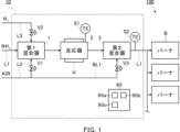
- FIG. 1 is a schematic diagram of a combustion facility including a fuel preheater according to a first embodiment.
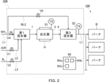
- FIG. 2 is a schematic diagram of a combustion facility including a fuel preheater according to a second embodiment.
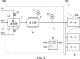
- FIG. 3 is a schematic diagram of a combustion facility including a fuel preheater according to a third embodiment.
- FIG. 1 is a schematic diagram of a combustion equipment 100 including a fuel preheater 10 according to the first embodiment.
- the fuel preheater 10 is provided in a fuel supply line L1 connected to the combustion equipment 100.
- Ammonia-containing gas flows through the fuel supply line L1.
- the combustion equipment 100 can be a boiler, an industrial furnace, a combustion furnace, or the like.
- the combustion equipment 100 is not limited to these, and can be various types of equipment that uses ammonia as fuel.
- the combustion equipment 100 may also be an existing facility. In another embodiment, the combustion equipment 100 may be a newly constructed facility.
- the combustion equipment 100 includes one or more burners B.
- Burner B burns a fuel containing ammonia.
- burner B may burn a mixture of ammonia and other fuels such as pulverized coal. Burner B may also burn only ammonia. Burner B may also burn a fuel that does not contain ammonia, if necessary.
- the fuel preheater 10 includes a first mixer 1, a reactor 2, a second mixer 3, and a control device 90.
- the fuel preheater 10 may further include other components not shown.
- the first mixer 1 is provided in the fuel supply line L1.
- the first mixer 1 may be installed on an existing fuel supply line L1 connected to an existing combustion equipment 100.
- the first mixer 1 is a gas mixer.
- the fuel supply line L1 supplies ammonia to the first mixer 1.
- the fuel supply line L1 supplies gaseous ammonia to the first mixer 1.
- An oxidizer supply line L2 is connected to the first mixer 1.
- the oxidizer supply line L2 supplies an oxidizer (e.g., air) to the first mixer 1.
- a valve (first valve) V1 is provided in the oxidizer supply line L2.
- the valve V1 is connected to the control device 90 via wired or wireless communication and is controlled by the control device 90.
- the control device 90 adjusts the flow rate of the oxidizer supplied to the first mixer 1 by controlling the opening degree of the valve V1.
- the first mixer 1 mixes the ammonia flowing through the fuel supply line L1 with the oxidizer supplied from the oxidizer supply line L2 to generate a mixed gas containing ammonia and the oxidizer.
- the mixed gas flows through the fuel supply line L1 and is supplied to the reactor 2.
- a nitrogen supply line L3 is connected to the first mixer 1.
- the nitrogen supply line L3 supplies nitrogen to the first mixer 1.
- a valve V2 is provided on the nitrogen supply line L3.
- the valve V2 is connected to the control device 90 via wired or wireless communication and is controlled by the control device 90.
- the control device 90 adjusts the flow rate of nitrogen supplied to the first mixer 1 by controlling the opening degree of the valve V2.
- the reactor 2 is provided downstream of the first mixer 1 in the fuel supply line L1. Similar to the first mixer 1, the reactor 2 may be installed on an existing fuel supply line L1 connected to an existing combustion facility 100.
- the reactor 2 receives the mixed gas from the first mixer 1.
- the reactor 2 includes a catalyst that promotes the reaction of ammonia to cause an exothermic reaction. Specifically, the catalyst promotes the reaction of at least a portion of the ammonia in the mixed gas supplied from the first mixer 1, causing catalytic combustion.
- the mixed gas is heated by the catalytic combustion. The heated mixed gas flows through the fuel supply line L1 and is supplied to the second mixer 3.
- the catalyst includes a transition element (which may also be referred to as a transition metal).
- the catalyst may include a precious metal such as Ru.
- the catalyst may include a non-precious metal such as Fe, Co, or Ni among the transition elements.
- the non-precious metal may exhibit high activity when combined with a specific support.
- a specific support for example, an oxide such as Al 2 O 3 or SiO 2 may be used. Also, if necessary, a support capable of suppressing sintering such as CeO 2 may be used.
- the reactor 2 is provided with a temperature sensor S1.
- the temperature sensor S1 is configured to measure the temperature of the catalyst.
- the temperature sensor S1 is connected to the control device 90 so as to be able to communicate with the control device 90 via wire or wirelessly, and transmits the measurement data to the control device 90.
- the reactor 2 is provided with a heating means H.
- the heating means H heats the catalyst.
- the heating means H may include an electric heater.
- the heating means H may include a first heat exchanger that heats the catalyst with exhaust gas from the combustion equipment 100.
- the heating means H may include a second heat exchanger that heats the catalyst with steam extracted from the combustion equipment 100.
- the heating means H is connected to the control device 90 so as to be able to communicate with it via wire or wirelessly, and is controlled by the control device 90.
- the control device 90 starts the operation of the heating means H and heats the catalyst until the temperature measured by the temperature sensor S1 reaches the temperature at which the catalyst starts to become active (e.g., 400°C).
- the control device 90 stops the operation of the heating means H. From this point on, the catalyst is maintained at a sufficient temperature by catalytic combustion.
- the second mixer 3 is provided downstream of the reactor 2 in the fuel supply line L1. Similar to the first mixer 1 and the reactor 2, the second mixer 3 may be installed on an existing fuel supply line L1 connected to an existing combustion facility 100. For example, the second mixer 3 is a gas mixer. The second mixer 3 receives the heated mixed gas from the reactor 2.
- the second mixer 3 is connected to the oxidant supply line L2 by a bypass line (first bypass line) BL1.
- the bypass line BL1 connects the oxidant supply line L2 directly to the second mixer 3 without passing through the first mixer 1 and the reactor 2. Therefore, at least a portion of the oxidant flowing through the oxidant supply line L2 is supplied to the first mixer 1, and the remainder of the oxidant is supplied to the second mixer 3.
- a valve V3 is provided in the bypass line BL1.
- the valve V3 is connected to the control device 90 via wired or wireless communication and is controlled by the control device 90.
- the control device 90 adjusts the flow rate of the oxidizer supplied to the second mixer 3 by controlling the opening degree of the valve V3.
- the second mixer 3 further mixes the mixed gas flowing through the fuel supply line L1 with the oxidizer supplied from the bypass line BL1.
- the mixed gas flows through the fuel supply line L1 and is supplied to the burner B as fuel (premixed combustion method).
- the burner B may be of a diffusion combustion type.
- a temperature sensor S2 is provided in the fuel supply line L1 downstream of the reactor 2, specifically, in this embodiment, downstream of the second mixer 3.
- the temperature sensor S2 is configured to measure the temperature of the mixed gas flowing through the fuel supply line L1.
- the temperature sensor S2 is connected to the control device 90 so as to be able to communicate with the control device 90 via wire or wirelessly, and transmits the measurement data to the control device 90.
- the fuel supply line L1 branches into multiple lines downstream of the temperature sensor S2 and is connected to each of the multiple burners B.
- the control device 90 controls the fuel preheater 10.
- the control device 90 may also control at least some of the components of the combustion equipment 100.
- the combustion equipment 100 may be equipped with a main control device (not shown), and the control device 90 may communicate with the main control device.
- the control device 90 includes components such as a processor 90a, a storage device 90b, and a connector 90c, and these components are connected to each other via a bus.
- the processor 90a includes a CPU (Central Processing Unit), etc.
- the storage device 90b includes a hard disk, a ROM in which programs and the like are stored, and a RAM as a work area, etc.
- the control device 90 is connected to each component of the fuel preheater 10 via the connector 90c so as to be able to communicate with each component via a wired or wireless connection.
- the control device 90 may further include other components, such as a display device such as a liquid crystal display or a touch panel, and an input device such as a keyboard, a button, or a touch panel.
- the operation of the control device 90 may be realized by having the processor 90a execute a program stored in the storage device 90b.
- the catalyst can cause both reactions (1) and (2).
- the control device 90 may control the valve V1 to adjust the amount of oxidant allocated from the oxidant supply line L2 to the first mixer 1, i.e., the amount of oxidant supplied to the reactor 2, so that most of the oxidant in the mixed gas supplied to the reactor 2 is used by the exothermic reaction (2).
- the control device 90 may also control the valve V3 as necessary.
- controller 90 increases the flow rate of oxidant supplied to reactor 2 from oxidant supply line L2. In contrast, for example, if the amount of oxidant supplied to reactor 2 is excessive, controller 90 reduces the flow rate of oxidant supplied to reactor 2 from oxidant supply line L2.
- the oxidizer required for combustion in burner B is supplied from oxidizer supply line L2 via bypass line BL1 to second mixer 3, where it is mixed with the heated mixed gas.
- the control device 90 controls valve V3 to adjust the amount of oxidizer allocated from oxidizer supply line L2 to bypass line BL1, i.e., the amount of oxidizer supplied to second mixer 3.
- the control device 90 may also control valve V1 as necessary.
- the controller 90 may increase the flow rate of oxidizer supplied from the oxidizer supply line L2 to the second mixer 3. In contrast, for example, if the amount of oxidizer supplied to burner B is excessive, the controller 90 may reduce the flow rate of oxidizer supplied from the oxidizer supply line L2 to the second mixer 3.
- the control device 90 also stores a predetermined threshold value in the memory device 90b.
- This threshold value is associated with the temperature at which the material forming the fuel supply line L1 starts to nitride.
- the fuel supply line L1 may be formed from a steel such as stainless steel. It is known that many steels become nitrided when exposed to an environment containing ammonia at approximately 400°C to 600°C. Therefore, most steels will not nitride even when exposed to an environment containing ammonia as long as the temperature is below the above range.
- the threshold value may be, for example, 400°C.
- the threshold value may also be determined by testing. For example, a test piece made of the same material as that forming the fuel supply line L1 is placed in an environment simulating the inside of the fuel supply line L1. The environment is maintained for a predetermined period of time (for example, one month, multiple months, one year, or multiple years). The nitrided layer depth of the test piece is then measured, and the nitriding rate per year (mm/year) is calculated. This test is performed at multiple temperatures. For example, the temperature at which the nitriding rate is less than a predetermined value may be determined as the threshold value (for example, less than 1 mm/year). For example, the nitrided layer depth may be measured by the "measurement method by hardness test” or “measurement method by metal structure test” of the "method of measuring the nitrided layer depth of steel" defined in JIS G0562.
- the control device 90 may adjust the flow rate of the oxidant supplied to the reactor 2 and the flow rate of the oxidant supplied to the second mixer 3 by controlling at least one of the valves V1 and V3 so that the temperature of the mixed gas measured by the temperature sensor S2 is below a threshold value.
- control device 90 may open valve V2 and add nitrogen to the mixed gas as an emergency coolant.
- the fuel supply line L1 may be provided with a valve (not shown) for adjusting the flow rate of ammonia supplied to the first mixer 1.
- Each of the lines L1, L2, and L3 may be provided with a pump (not shown) for sending fluid.
- These valves and pumps may be connected to the control device 90 in a wired or wireless manner so as to be able to communicate with each other, and may be controlled by the control device 90.
- the control device 90 starts the operation of the heating means H.
- the catalyst is heated until the temperature measured by the temperature sensor S1 reaches the temperature at which the catalyst starts to become active.
- the control device 90 controls the valve V1 to start supplying the oxidizer to the first mixer 1.
- the first mixer 1 also receives ammonia from the fuel supply line L1.
- the first mixer 1 mixes the ammonia and the oxidizer to generate a mixed gas.
- the mixed gas is supplied to the reactor 2 by the fuel supply line L1.
- the control device 90 also stops the operation of the heating means H. From this point on, the catalyst is maintained at a sufficient temperature by catalytic combustion.
- At least a portion of the oxidant in the mixed gas reacts with ammonia on the catalyst in the reactor 2, causing catalytic combustion. This heats the mixed gas.
- the heated mixed gas is supplied to the second mixer 3 by the fuel supply line L1.
- the control device 90 controls the valve V3 to start supplying the oxidizer required for combustion in the burner B to the second mixer 3.
- the second mixer 3 also receives heated mixed gas from the fuel supply line L1.
- the second mixer 3 further mixes the ammonia and the oxidizer.
- the heated mixed gas is supplied to the multiple burners B as premixed fuel via the fuel supply line L1.
- the fuel preheater 10 as described above includes a first mixer 1 provided in a fuel supply line L1 connected to a combustion facility 100 that burns a fuel containing ammonia, and a reactor 2 provided downstream of the first mixer 1 in the fuel supply line L1.
- the fuel supply line L1 supplies ammonia to the first mixer 1.
- the first mixer 1 is connected to an oxidizer supply line L2 that supplies an oxidizer, and mixes the ammonia flowing through the fuel supply line L1 with the oxidizer from the oxidizer supply line L2 to generate a mixed gas.
- the reactor 2 includes a catalyst that promotes the reaction of ammonia to cause an exothermic reaction.
- the catalyst causes an exothermic reaction by at least a portion of the ammonia in the mixed gas supplied from the first mixer 1, and heats the mixed gas.
- the mixed gas containing ammonia and heated by the exothermic reaction in the reactor 2 can be supplied to the combustion facility 100. Since the mixed gas is heated by the exothermic reaction, the ammonia in the mixed gas is also heated, and the combustion speed of the ammonia is increased. Therefore, fuel can be supplied to the combustion equipment 100 with an increased combustion rate.
- the fuel preheater 10 includes a second mixer 3 provided downstream of the reactor 2 in the fuel supply line L1.
- the second mixer 3 is connected to the oxidizer supply line L2 by a bypass line BL1, and mixes the mixed gas supplied from the reactor 2 with the oxidizer supplied from the bypass line BL1.
- the fuel preheater 10 includes a valve V1 provided in the oxidizer supply line L2 to adjust the flow rate of the oxidizer, a temperature sensor S2 provided in the fuel supply line L1 downstream of the reactor 2 to measure the temperature of the mixed gas, and a control device 90 communicatively connected to the valve V1 and the temperature sensor S2.
- the control device 90 stores a predetermined threshold value associated with the temperature at which the material forming the fuel supply line L1 starts to be nitriding.
- the control device 90 controls the valve V1 to adjust the flow rate of the oxidizer supplied to the first mixer 1 so that the temperature of the mixed gas measured by the temperature sensor S2 is below the threshold value.
- the reactor 2 also includes a heating means H for heating the catalyst, which may include a heater.
- a heating means H for heating the catalyst which may include a heater.
- the heating means H may include a first heat exchanger that heats the catalyst with exhaust gas from the combustion equipment 100.
- the catalyst can be quickly heated to a temperature at which the catalyst begins to become active, and the exhaust gas can be reused.
- the heating means H may include a second heat exchanger that heats the catalyst with steam extracted from the combustion equipment 100.
- the catalyst can be quickly heated to a temperature at which the catalyst begins to become active.
- the fuel preheater 10 supplies the mixed gas to multiple burners B of the combustion equipment 100. With this configuration, there is no need to provide a fuel preheater for each burner B.
- the exothermic reaction in the catalyst of reactor 2 is catalytic combustion. With this configuration, flameless combustion mainly occurs on the surface of reactor 2, making it very safe.
- the air ratio in reactor 2 can be changed and the temperature of the mixed gas can be controlled.
- the ignition ability and combustion stability of the flame-retardant ammonia in burner B can be improved.
- the fuel preheater 10 as described above can be installed in an existing combustion facility 100.
- the method of installing the fuel preheater 10 in the combustion facility 100 according to the present embodiment includes preparing a first mixer 1 configured to mix ammonia and an oxidizer, preparing a reactor 2 including a catalyst that causes an exothermic reaction by ammonia, and installing the first mixer 1 in a fuel supply line L1 connected to the combustion facility 100 that burns a fuel including ammonia.
- the fuel supply line L1 supplies ammonia to the first mixer 1.
- the method according to the present embodiment also includes connecting an oxidizer supply line L2 that supplies an oxidizer to the first mixer 1.
- the first mixer 1 mixes the ammonia flowing through the fuel supply line L1 with the oxidizer from the oxidizer supply line L2 to generate a mixed gas.
- the method according to the present embodiment also includes installing a reactor 2 downstream of the first mixer 1 in the fuel supply line L1.
- the catalyst causes an exothermic reaction by at least a portion of the ammonia in the mixed gas supplied from the first mixer 1, and heats the mixed gas. This configuration makes it possible to supply fuel at an increased combustion rate to existing combustion equipment 100 without major construction work.
- fuel preheaters 10, 10A, and 10B include components surrounded by dashed lines. Therefore, the method of installing fuel preheater 10, 10A, or 10B to combustion equipment 100 according to the present disclosure may further include installing components other than first mixer 1 and reactor 2 within the dashed lines to existing fuel supply line L1.
- FIG. 2 is a schematic diagram of a combustion equipment 100 including a fuel preheater 10A according to the second embodiment.
- the fuel preheater 10A differs from the fuel preheater 10 according to the first embodiment in that it includes an ammonia bypass line (second bypass line) BL2 and a third mixer 4 instead of the oxidizer bypass line BL1 and the second mixer 3.
- the fuel preheater 10A may be the same as the fuel preheater 10.
- the third mixer 4 is provided downstream of the reactor 2 in the fuel supply line L1.
- the third mixer 4 may be installed on an existing fuel supply line L1 connected to an existing combustion equipment 100.
- the third mixer 4 is a gas mixer.
- the third mixer 4 receives the heated mixed gas from the reactor 2.
- the third mixer 4 is connected to the fuel supply line L1 at a position upstream of the first mixer 1 by the bypass line BL2.
- the bypass line BL2 connects the fuel supply line L1 directly to the third mixer 4 without passing through the first mixer 1 and the reactor 2. Therefore, at least a portion of the ammonia flowing through the fuel supply line L1 is supplied to the first mixer 1, and the remainder of the ammonia is supplied to the third mixer 4.
- a valve (second valve) V4 is provided in the fuel supply line L1 between the connection to the bypass line BL2 and the first mixer 1.
- the valve V4 is connected to the control device 90 so as to be able to communicate with it via wire or wirelessly, and is controlled by the control device 90.
- the control device 90 adjusts the flow rate of ammonia supplied to the first mixer 1 by controlling the opening degree of the valve V4.
- a valve V5 is provided in the bypass line BL2.
- the valve V5 is connected to the control device 90 via wired or wireless communication and is controlled by the control device 90.
- the control device 90 adjusts the flow rate of ammonia supplied to the third mixer 4 by controlling the opening degree of the valve V5.
- the third mixer 4 further mixes the mixed gas flowing through the fuel supply line L1 with ammonia supplied from the bypass line BL2.
- the mixed gas flows through the fuel supply line L1 and is supplied to the burner B as fuel.
- control device 90 may control the valve V4 to adjust the flow rate of ammonia allocated from the fuel supply line L1 to the first mixer 1, i.e., the flow rate of ammonia supplied to the reactor 2, so that most of the ammonia in the mixed gas supplied to the reactor 2 is used by the exothermic reaction (2).
- the control device 90 may also control the valve V5 as necessary.
- the controller 90 may increase the flow rate of ammonia supplied to the reactor 2 from the fuel supply line L1. In contrast, for example, if the reactor 2 is overheating the mixed gas, the controller 90 may reduce the flow rate of oxidant supplied to the reactor 2 from the fuel supply line L1.
- the ammonia required for combustion in burner B is supplied from fuel supply line L1 through bypass line BL2 to third mixer 4, where it is mixed with the heated mixed gas.
- the control device 90 controls valve V5 to adjust the amount of ammonia allocated from fuel supply line L1 to bypass line BL2, i.e., the amount of ammonia supplied to third mixer 4.
- the control device 90 may also control valve V4 as necessary.
- the controller 90 may increase the flow rate of ammonia supplied from fuel supply line L1 to the third mixer 4. In contrast, for example, if the amount of ammonia supplied to burner B is excessive, the controller 90 may reduce the flow rate of ammonia supplied from fuel supply line L1 to the third mixer 4.
- control device 90 may control at least one of the valves V4 and V5 to adjust the flow rate of ammonia supplied to the reactor 2 and the flow rate of ammonia supplied to the third mixer 4 so that the temperature of the mixed gas measured by the temperature sensor S2 is less than a threshold value (e.g., 400°C).
- a threshold value e.g. 400°C
- the fuel preheater 10A as described above has substantially the same effects as the fuel preheater 10 according to the first embodiment.
- the fuel preheater 10A also includes a third mixer 4 that is provided downstream of the reactor 2 in the fuel supply line L1.
- the third mixer 4 is connected to the fuel supply line L1 at a position upstream of the first mixer 1 by a bypass line BL2, and mixes the mixed gas supplied from the reactor 2 with the ammonia supplied from the bypass line BL2. With this configuration, the amount of ammonia supplied from the fuel supply line L1 to the reactor 2 can be adjusted more precisely.
- the fuel preheater 10A includes a valve V4 provided upstream of the first mixer 1 in the fuel supply line L1 to adjust the flow rate of ammonia supplied to the first mixer 1, a temperature sensor S2 provided downstream of the reactor 2 in the fuel supply line L1 to measure the temperature of the mixed gas, and a control device 90 communicatively connected to the valve V4 and the temperature sensor S2.
- the control device 90 stores a predetermined threshold value associated with the temperature at which the material forming the fuel supply line L1 starts to be nitriding.
- the control device 90 controls the valve V4 to adjust the flow rate of ammonia supplied to the first mixer 1 so that the temperature of the mixed gas measured by the temperature sensor S2 is less than the threshold value.
- FIG. 3 is a schematic diagram of a combustion equipment 100 including a fuel preheater 10B according to a third embodiment.
- the fuel preheater 10B differs from the fuel preheater 10 according to the first embodiment in that it does not include a bypass line BL1 and a second mixer 3. In other respects, the fuel preheater 10B may be the same as the fuel preheater 10.
- each burner B of the combustion equipment 100 is of a diffusion combustion type. Air necessary for diffusion combustion is supplied to each burner B.
- the combustion equipment 100 may include components (not shown) such as an air register and a damper for adjusting the amount of air to each burner B. Note that in FIG. 3, air is shown only for the top burner B.
- control device 90 controls the valve V1 to adjust the amount of oxidant supplied from the oxidant supply line L2 through the first mixer 1 to the reactor 2 so that most of the oxidant in the mixed gas supplied to the reactor 2 is used by the exothermic reaction (2).
- control device 90 controls the valve V1 to adjust the flow rate of the oxidant supplied to the reactor 2 so that the temperature of the mixed gas measured by the temperature sensor S2 is less than a threshold value (e.g., 400°C).
- a threshold value e.g. 400°C
- the fuel preheater 10B described above has substantially the same effects as the fuel preheater 10 according to the first embodiment.
- the present disclosure can facilitate the use of ammonia leading to reduced CO2 emissions, thereby contributing, for example, to Sustainable Development Goal (SDG) Goal 7 "Ensure access to affordable, reliable, sustainable and modern energy” and Goal 13 "Take urgent action to combat climate change and its impacts.”
- SDG Sustainable Development Goal
Landscapes
- Engineering & Computer Science (AREA)
- Chemical & Material Sciences (AREA)
- Combustion & Propulsion (AREA)
- Mechanical Engineering (AREA)
- General Engineering & Computer Science (AREA)
- Chemical Kinetics & Catalysis (AREA)
- Organic Chemistry (AREA)
- Health & Medical Sciences (AREA)
- General Health & Medical Sciences (AREA)
- Inorganic Chemistry (AREA)
- Feeding And Controlling Fuel (AREA)
Priority Applications (4)
| Application Number | Priority Date | Filing Date | Title |
|---|---|---|---|
| JP2025527478A JPWO2024257438A1 (enExample) | 2023-06-14 | 2024-03-29 | |
| KR1020257032063A KR20250167603A (ko) | 2023-06-14 | 2024-03-29 | 연료 예열기 |
| AU2024305213A AU2024305213A1 (en) | 2023-06-14 | 2024-03-29 | Fuel preheater |
| CN202480015671.7A CN120813804A (zh) | 2023-06-14 | 2024-03-29 | 燃料预热器 |
Applications Claiming Priority (2)
| Application Number | Priority Date | Filing Date | Title |
|---|---|---|---|
| JP2023097818 | 2023-06-14 | ||
| JP2023-097818 | 2023-06-14 |
Related Child Applications (1)
| Application Number | Title | Priority Date | Filing Date |
|---|---|---|---|
| US19/317,700 Continuation US20260002669A1 (en) | 2023-06-14 | 2025-09-03 | Fuel preheater |
Publications (1)
| Publication Number | Publication Date |
|---|---|
| WO2024257438A1 true WO2024257438A1 (ja) | 2024-12-19 |
Family
ID=93851803
Family Applications (1)
| Application Number | Title | Priority Date | Filing Date |
|---|---|---|---|
| PCT/JP2024/013083 Pending WO2024257438A1 (ja) | 2023-06-14 | 2024-03-29 | 燃料予熱器 |
Country Status (5)
| Country | Link |
|---|---|
| JP (1) | JPWO2024257438A1 (enExample) |
| KR (1) | KR20250167603A (enExample) |
| CN (1) | CN120813804A (enExample) |
| AU (1) | AU2024305213A1 (enExample) |
| WO (1) | WO2024257438A1 (enExample) |
Citations (9)
| Publication number | Priority date | Publication date | Assignee | Title |
|---|---|---|---|---|
| JP2008039254A (ja) * | 2006-08-03 | 2008-02-21 | Gifu Univ | マイクロコンバスタ及びマイクロ発電装置 |
| JP2012255420A (ja) * | 2011-06-10 | 2012-12-27 | Nippon Shokubai Co Ltd | ガスタービンシステム |
| CN203892008U (zh) * | 2014-06-17 | 2014-10-22 | 厦门大学 | 一种氨发动机系统 |
| JP2015094248A (ja) * | 2013-11-11 | 2015-05-18 | 三菱日立パワーシステムズ株式会社 | 高湿分利用ガスタービンシステム |
| JP2018095512A (ja) * | 2016-12-13 | 2018-06-21 | 三菱日立パワーシステムズ株式会社 | 水素含有燃料供給システム、火力発電プラント、燃焼ユニット及び燃焼ユニットの改造方法 |
| CN112902163A (zh) * | 2021-03-08 | 2021-06-04 | 山东大学 | 一种基于氨分解的掺氢低氮燃烧系统和方法 |
| JP2021110463A (ja) * | 2020-01-06 | 2021-08-02 | 株式会社Kri | アンモニア燃焼装置及びアンモニア燃料電池システム |
| JP2023012119A (ja) * | 2021-07-13 | 2023-01-25 | 株式会社豊田自動織機 | 燃焼器及び改質装置 |
| WO2023037642A1 (ja) * | 2021-09-09 | 2023-03-16 | 中外炉工業株式会社 | アンモニア燃料燃焼装置 |
Family Cites Families (3)
| Publication number | Priority date | Publication date | Assignee | Title |
|---|---|---|---|---|
| EP0832399B1 (de) | 1995-06-12 | 2000-01-12 | Siemens Aktiengesellschaft | Katalytische zündbrenner einer gasturbine |
| CN107300169B (zh) | 2016-04-14 | 2019-12-27 | 中国科学院大连化学物理研究所 | 一种极低污染物排放的催化无焰燃烧装置及燃烧方法 |
| KR101688894B1 (ko) | 2016-08-08 | 2016-12-23 | 주식회사 지엔티엔에스 | 고온 연소촉매를 이용한 버너 |
-
2024
- 2024-03-29 JP JP2025527478A patent/JPWO2024257438A1/ja active Pending
- 2024-03-29 WO PCT/JP2024/013083 patent/WO2024257438A1/ja active Pending
- 2024-03-29 AU AU2024305213A patent/AU2024305213A1/en active Pending
- 2024-03-29 KR KR1020257032063A patent/KR20250167603A/ko active Pending
- 2024-03-29 CN CN202480015671.7A patent/CN120813804A/zh active Pending
Patent Citations (9)
| Publication number | Priority date | Publication date | Assignee | Title |
|---|---|---|---|---|
| JP2008039254A (ja) * | 2006-08-03 | 2008-02-21 | Gifu Univ | マイクロコンバスタ及びマイクロ発電装置 |
| JP2012255420A (ja) * | 2011-06-10 | 2012-12-27 | Nippon Shokubai Co Ltd | ガスタービンシステム |
| JP2015094248A (ja) * | 2013-11-11 | 2015-05-18 | 三菱日立パワーシステムズ株式会社 | 高湿分利用ガスタービンシステム |
| CN203892008U (zh) * | 2014-06-17 | 2014-10-22 | 厦门大学 | 一种氨发动机系统 |
| JP2018095512A (ja) * | 2016-12-13 | 2018-06-21 | 三菱日立パワーシステムズ株式会社 | 水素含有燃料供給システム、火力発電プラント、燃焼ユニット及び燃焼ユニットの改造方法 |
| JP2021110463A (ja) * | 2020-01-06 | 2021-08-02 | 株式会社Kri | アンモニア燃焼装置及びアンモニア燃料電池システム |
| CN112902163A (zh) * | 2021-03-08 | 2021-06-04 | 山东大学 | 一种基于氨分解的掺氢低氮燃烧系统和方法 |
| JP2023012119A (ja) * | 2021-07-13 | 2023-01-25 | 株式会社豊田自動織機 | 燃焼器及び改質装置 |
| WO2023037642A1 (ja) * | 2021-09-09 | 2023-03-16 | 中外炉工業株式会社 | アンモニア燃料燃焼装置 |
Also Published As
| Publication number | Publication date |
|---|---|
| AU2024305213A1 (en) | 2025-09-11 |
| JPWO2024257438A1 (enExample) | 2024-12-19 |
| KR20250167603A (ko) | 2025-12-01 |
| CN120813804A (zh) | 2025-10-17 |
Similar Documents
| Publication | Publication Date | Title |
|---|---|---|
| JP7385476B2 (ja) | アンモニア燃焼装置及びアンモニア燃料電池システム | |
| US12135128B2 (en) | Method to operate a modulating burner | |
| US7594394B2 (en) | Catalytic reactor and method for the combustion of fuel-air mixtures by means of a catalytic reactor | |
| CA2561255A1 (en) | Device and method for flame stabilization in a burner | |
| US20130074515A1 (en) | Gas turbine engine system and method of providing a fuel supplied to one or more combustors in a gas turbine engine system | |
| WO2023037642A1 (ja) | アンモニア燃料燃焼装置 | |
| US7444820B2 (en) | Method and system for rich-lean catalytic combustion | |
| Smith et al. | Rich-catalytic lean-burn combustion for low-single-digit NO x gas turbines | |
| WO2024257438A1 (ja) | 燃料予熱器 | |
| US6658856B2 (en) | Hybrid lean premixing catalytic combustion system for gas turbines | |
| US20260002669A1 (en) | Fuel preheater | |
| KR20240134167A (ko) | 플레어 스택 및 플레어 스택을 구비하는 시스템 | |
| CN118742722A (zh) | 燃烧装置以及燃气轮机 | |
| WO2024257430A1 (ja) | 燃焼器 | |
| JP2002025597A (ja) | 燃料電池用の改質装置とその運転方法 | |
| JP2025005757A (ja) | 燃焼器および燃焼方法 | |
| US20030126863A1 (en) | Air staged catalytic combusion system | |
| JP2023176174A (ja) | アンモニア改質燃焼システム、及びアンモニア改質燃焼方法 | |
| Smith et al. | Rich-catalytic lean-burn combustion for low-single-digit NOx gas turbines | |
| JPH0419445B2 (enExample) | ||
| WO2025109966A1 (ja) | アンモニア分解システムおよびアンモニアを分解するための方法 | |
| Chen | Combustion characteristics of small alkanes on noble metal surfaces in pre-mixed homogeneous-heterogeneous hybrid systems | |
| JP2025082614A (ja) | アンモニア改質燃焼システム | |
| JP2025015186A (ja) | アンモニア燃焼装置 | |
| JP2025125904A (ja) | 燃料吹込方法 |
Legal Events
| Date | Code | Title | Description |
|---|---|---|---|
| 121 | Ep: the epo has been informed by wipo that ep was designated in this application |
Ref document number: 24823061 Country of ref document: EP Kind code of ref document: A1 |
|
| WWE | Wipo information: entry into national phase |
Ref document number: 2025527478 Country of ref document: JP |
|
| WWE | Wipo information: entry into national phase |
Ref document number: AU2024305213 Country of ref document: AU |
|
| WWE | Wipo information: entry into national phase |
Ref document number: 202480015671.7 Country of ref document: CN |
|
| ENP | Entry into the national phase |
Ref document number: 2024305213 Country of ref document: AU Date of ref document: 20240329 Kind code of ref document: A |
|
| ENP | Entry into the national phase |
Ref document number: 1020257032063 Country of ref document: KR Free format text: ST27 STATUS EVENT CODE: A-0-1-A10-A15-NAP-PA0105 (AS PROVIDED BY THE NATIONAL OFFICE) |
|
| WWE | Wipo information: entry into national phase |
Ref document number: KR1020257032063 Country of ref document: KR |
|
| WWP | Wipo information: published in national office |
Ref document number: 202480015671.7 Country of ref document: CN |