WO2024257366A1 - 電気接続箱 - Google Patents
電気接続箱 Download PDFInfo
- Publication number
- WO2024257366A1 WO2024257366A1 PCT/JP2023/033702 JP2023033702W WO2024257366A1 WO 2024257366 A1 WO2024257366 A1 WO 2024257366A1 JP 2023033702 W JP2023033702 W JP 2023033702W WO 2024257366 A1 WO2024257366 A1 WO 2024257366A1
- Authority
- WO
- WIPO (PCT)
- Prior art keywords
- relays
- relay
- terminals
- pair
- junction box
- Prior art date
- Legal status (The legal status is an assumption and is not a legal conclusion. Google has not performed a legal analysis and makes no representation as to the accuracy of the status listed.)
- Ceased
Links
Images




Classifications
-
- H—ELECTRICITY
- H01—ELECTRIC ELEMENTS
- H01H—ELECTRIC SWITCHES; RELAYS; SELECTORS; EMERGENCY PROTECTIVE DEVICES
- H01H45/00—Details of relays
- H01H45/14—Terminal arrangements
-
- B—PERFORMING OPERATIONS; TRANSPORTING
- B60—VEHICLES IN GENERAL
- B60R—VEHICLES, VEHICLE FITTINGS, OR VEHICLE PARTS, NOT OTHERWISE PROVIDED FOR
- B60R16/00—Electric or fluid circuits specially adapted for vehicles and not otherwise provided for; Arrangement of elements of electric or fluid circuits specially adapted for vehicles and not otherwise provided for
- B60R16/02—Electric or fluid circuits specially adapted for vehicles and not otherwise provided for; Arrangement of elements of electric or fluid circuits specially adapted for vehicles and not otherwise provided for electric constitutive elements
-
- H—ELECTRICITY
- H01—ELECTRIC ELEMENTS
- H01H—ELECTRIC SWITCHES; RELAYS; SELECTORS; EMERGENCY PROTECTIVE DEVICES
- H01H45/00—Details of relays
- H01H45/02—Bases; Casings; Covers
- H01H45/04—Mounting complete relay or separate parts of relay on a base or inside a case
-
- H—ELECTRICITY
- H01—ELECTRIC ELEMENTS
- H01H—ELECTRIC SWITCHES; RELAYS; SELECTORS; EMERGENCY PROTECTIVE DEVICES
- H01H45/00—Details of relays
- H01H45/12—Ventilating; Cooling; Heating
-
- H—ELECTRICITY
- H01—ELECTRIC ELEMENTS
- H01H—ELECTRIC SWITCHES; RELAYS; SELECTORS; EMERGENCY PROTECTIVE DEVICES
- H01H50/00—Details of electromagnetic relays
- H01H50/12—Ventilating; Cooling; Heating
-
- H—ELECTRICITY
- H01—ELECTRIC ELEMENTS
- H01H—ELECTRIC SWITCHES; RELAYS; SELECTORS; EMERGENCY PROTECTIVE DEVICES
- H01H9/00—Details of switching devices, not covered by groups H01H1/00 - H01H7/00
- H01H9/02—Bases, casings, or covers
-
- H—ELECTRICITY
- H02—GENERATION; CONVERSION OR DISTRIBUTION OF ELECTRIC POWER
- H02G—INSTALLATION OF ELECTRIC CABLES OR LINES, OR OF COMBINED OPTICAL AND ELECTRIC CABLES OR LINES
- H02G3/00—Installations of electric cables or lines or protective tubing therefor in or on buildings, equivalent structures or vehicles
- H02G3/02—Details
- H02G3/08—Distribution boxes; Connection or junction boxes
- H02G3/16—Distribution boxes; Connection or junction boxes structurally associated with support for line-connecting terminals within the box
-
- H—ELECTRICITY
- H05—ELECTRIC TECHNIQUES NOT OTHERWISE PROVIDED FOR
- H05K—PRINTED CIRCUITS; CASINGS OR CONSTRUCTIONAL DETAILS OF ELECTRIC APPARATUS; MANUFACTURE OF ASSEMBLAGES OF ELECTRICAL COMPONENTS
- H05K7/00—Constructional details common to different types of electric apparatus
- H05K7/20—Modifications to facilitate cooling, ventilating, or heating
Definitions
- the present invention relates to an electrical connection box in which a relay is housed in a case.
- electrical connection boxes used in automobiles and the like are configured to mount electronic components such as relays and fuses in a case of a given shape made of resin or the like, and to electrically connect the input/output terminals of these electronic components to bus bars held in the case and terminals connected to external loads (see, for example, Patent Document 1).
- Joule heat is generated at current-carrying points such as the input/output terminals of the electronic components.
- Joule heat can be greater than at other points due to the large contact resistance. Since the heat generated at such contact points is also transferred to the internal mechanism of the electronic components via the input/output terminals, from the perspective of operating the electronic components properly for a long period of time, it is desirable to efficiently dissipate the heat generated at the contact points to the outside of the electronic components.
- One of the objectives of the present invention is to provide an electrical junction box that has excellent heat dissipation properties from a relay housed in the case of the electrical junction box.
- the electrical connection box of the present invention has the following features:
- An electrical connection box comprising: Each of the pair of relays is a plurality of terminals connected to an internal circuit of the relay; and a protrusion having a shape protruding toward the gap in the vicinity of at least one of the plurality of terminals, The heat transfer member is configured to absorb heat emitted from the at least one terminal and transfer the heat in a direction away from the at least one terminal; It is an electrical junction box.
- FIG. 1 is a perspective view of an electrical junction box according to an embodiment of the present invention.
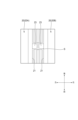
- FIG. 2 is a top view of the electrical junction box shown in FIG.
- FIG. 3 is an enlarged view of part B in FIG.
- FIG. 4 is a bottom view of the electrical junction box shown in FIG. 1 (only the bus bars and electronic components (relays and fuses) are shown).
- FIG. 5 is an enlarged bottom view of the relay shown in FIG.
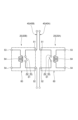
- FIG. 6 is a diagram for explaining the internal circuitry of the pair of relays shown in FIG.
- the electrical junction box 1 is typically a relay box that is mounted on a vehicle such as an automobile and houses electronic components such as relays and fuses. As shown in Figs. 1 to 6, the electrical junction box 1 comprises a case 10, a plurality of electronic components housed in the case 10 (specifically, relays 20 and fuses 30 (see Fig. 4)), and a plurality of bus bars 40 held by the case 10 (see Fig. 4).
- the front-to-back, left-to-right, and top-to-bottom directions are mutually perpendicular.
- the “top” and “bottom” sides respectively correspond to the “top” and “bottom” sides of the vehicle when the electrical junction box 1 is mounted on the vehicle. Note that these directions are defined merely for ease of explanation, and do not necessarily correspond to the front-to-back, left-to-right, and top-to-bottom directions of the vehicle when the electrical junction box 1 is mounted on the vehicle. Below, each of the components that make up the electrical junction box 1 will be explained in order.
- case 10 is a resin housing having a generally rectangular parallelepiped shape extending in the front-rear, left-right, and up-down directions.
- Case 10 may be made of a single resin molded body, or a combination of multiple resin molded bodies.
- case 10 may be made of resin in the parts that require insulation, such as the parts that hold the electronic components and bus bars 40, and other parts (e.g., the exterior parts) may be made of metal.
- a number of relays 20 are housed in the front region of the upper part of the case 10.
- Each of the relays 20 is housed in a corresponding housing portion (cavity) in the upper part of the case 10 from top to bottom.
- a rear region A adjacent to the rear side of the front region of the upper part of the case 10 is a region in which electronic components such as fuses 30 (see Figure 4) are housed.
- the fuses 30 and the like are also housed in corresponding housing portions (cavities) in the upper part of the case 10 from top to bottom.
- An electric wire insertion portion 11 is provided at the lower right end of the front surface of the case 10 (see Figures 1 and 2). From the electric wire insertion portion 11, electric wires 2 electrically connected to the bus bar 40 and electric wires 2 electrically connected to electronic components such as the relay 20 and the fuse 30 extend forward from the inside of the case 10 to the outside (see Figures 1 and 2).
- each of the multiple bus bars 40 held in the case 10 is an elongated metal plate having a predetermined shape when viewed from the top to bottom.
- Each of the multiple bus bars 40 is attached and held in a corresponding predetermined location on the lower part of the case 10 from bottom to top, with the plate thickness direction oriented in the direction perpendicular to the top to bottom direction (with the plate surface facing the direction perpendicular to the top to bottom direction).
- each of the multiple bus bars 40 is electrically connected to the input terminal or output terminal of one or more corresponding electronic components (such as relays 20 or fuses 30), and the multiple electronic components (such as relays 20 or fuses 30) are electrically connected to the electric wires 2 (see FIG. 1 and FIG. 2) via the multiple bus bars 40.
- the pair of relays 20A, 20B are relays for low-voltage circuits, but in some embodiments, they may be relays for high-voltage circuits.
- the resin relay body of each of the pair of relays 20A, 20B has a substantially rectangular parallelepiped shape extending in the front-rear, left-right, and up-down directions.
- the relay bodies of the pair of relays 20A, 20B are arranged so as to be aligned in the left-right direction with a gap S (see Figures 2 to 4) in the left-right direction.
- each relay body of the pair of relays 20A, 20B has a rectangular shape having one side 21 facing the gap S and an opposite side 22 on the opposite side to the one side 21.
- a protrusion 23 that protrudes toward the gap S is provided on one side surface 21 of each of the pair of relays 20A, 20B (see FIGS. 3 to 5).
- the protrusions 23 of the pair of relays 20A, 20B are arranged so that the protruding ends face each other with a gap in the left-right direction.
- Each of the pair of relays 20A, 20B has a plurality of terminals 51-54 (see Fig. 4-6) connected to an internal circuit 60 (see Fig. 6) built into the relay body.
- Each of the plurality of terminals 51-54 is a metal flat (tab-shaped) terminal provided so as to protrude downward from the lower end surface of each of the pair of relays 20A, 20B.
- the two terminals 51, 52 are arranged opposite each other with a gap in the left-right direction in an area closer to the one side surface 21 on which the protruding portion 23 is provided than the left-right center of the relay body.
- the protruding portion 23 is arranged near two of the plurality of terminals 51-54, the terminals 51, 52.
- the two terminals 53, 54 are arranged opposite each other with a gap in the front-rear direction in an area closer to the opposite side surface 22 than the left-right center of the relay body.
- the terminals 51 of the relays 20A and 20B function as, for example, input side contact terminals.
- the bus bar 40A is connected to the terminal 51 of the relay 20A via the connection terminal 41
- the bus bar 40B is connected to the terminal 51 of the relay 20B via the connection terminal 41.
- An electric wire (not shown) connected to an external power source (not shown) is connected to the bus bars 40A and 40B.
- the terminals 52 of the relays 20A and 20B function as, for example, output side contact terminals.
- an electric wire (not shown) connected to an external load (not shown) is connected to the terminals 52 of the relay 20A and 20B.
- Each of the bus bars 40A and 40B has a shape that extends generally in the front-rear direction, although it includes a part that is bent in a crank shape when viewed from the top-bottom direction.
- the internal circuit 60 of each of the pair of relays 20A, 20B has a switch section 61.
- the switch section 61 has a fixed contact 62 and a movable contact 63, and is connected to the terminals 51, 52.
- the switch section 61 is provided with a biasing member such as a spring (not shown), which biases the movable contact 63 in a direction away from the fixed contact 62.
- the internal circuit 60 has a coil portion 64 that is composed of a coil and an iron core (not shown) and functions as an electromagnet.
- the coil portion 64 is connected to the terminals 53 and 54.
- the terminals 53 and 54 function as coil terminals.
- the coil portion 64 generates a magnetic force when a control current is supplied via the terminals 53 and 54, and the magnetic force attracts the movable contact 63 against the biasing force of the biasing member.
- the movable contact 63 contacts the fixed contact 62 in the switch portion 61, and the switch portion 61 is in a closed state (ON).
- the switch portion 61 Conversely, when a current is not applied to the coil portion 64, the movable contact 63 is separated from the fixed contact 62 in the switch portion 61, and the switch portion 61 is in an open state (OFF).
- the operation of the pair of relays 20A, 20B is controlled, for example, by an ECU (Electronic Control Unit) (not shown).
- ECU Electronic Control Unit
- a control current is supplied from the ECU to the coil section 64 of relay 20A via terminals 53, 54 and the switch section 61 of relay 20A is closed, power from an external power source is supplied to an external load via relay 20A.
- a control current is supplied to the coil section 64 of relay 20B via terminals 53, 54 and the switch section 61 of relay 20B is closed, power from an external power source is supplied to an external load via relay 20B.
- each of the pair of relays 20A, 20B housed in the case 10 has a protrusion 23 that protrudes toward the gap S between the relays 20A, 20B.
- These protrusions 23 prevent the pair of relays 20A, 20B from being placed excessively close to each other, and an appropriate gap S exists between the pair of relays 20A, 20B.
- the protrusions 23 are placed near the two terminals 51, 52 of each of the pair of relays 20A, 20B.
- the electrical junction box 1 Since there is a gap S between the pair of relays 20A, 20B, Joule heat generated at each of the terminals 51, 52 of the relays 20A, 20B is not concentrated in an excessively narrow range, and heat dissipation is also promoted by the air flow through the gap S. Therefore, the electrical junction box 1 has excellent heat dissipation properties from the relays 20A, 20B housed in the case 10. In addition, compared to dissipating the heat generated by each of the terminals 51 and 52 to different locations, dissipating the heat generated by each of the terminals 51 and 52 in a lump into the above-mentioned gap S also contributes to the miniaturization of the electrical connection box 1.
- the pair of relays 20A and 20B are arranged so that the protrusion 23 of relay 20A and the protrusion 23 of relay 20B do not come into contact with each other. This makes it possible to widen the gap between the pair of relays 20A and 20B compared to when the protrusions 23 come into contact with each other.
- the protrusion 23 of relay 20A does not contact relay 20B, and the protrusion 23 of relay 20B does not contact relay 20A. This makes it possible to widen the gap S between the pair of relays 20A and 20B compared to when each protrusion 23 contacts the other relay 20.
- the protrusion 23 is disposed near two of the terminals 51, 52 among the multiple terminals 51 to 54. This allows the Joule heat generated at the two terminals 51, 52 of each of the relays 20A, 20B to be properly dissipated.
- the protruding end (right end) of the protruding portion 23 of relay 20A is closer to relay 20B than the terminal 51 of relay 20A
- the protruding end (left end) of the protruding portion 23 of relay 20B is closer to relay 20A than the terminal 51 of relay 20B. This allows the terminal 51 of relay 20A to be reliably positioned away from relay 20B, and the terminal 51 of relay 20B to be reliably positioned away from relay 20A. This allows the Joule heat generated at the terminal 51 to be properly dissipated.
- a protrusion 23 is provided on one side surface 21 of the relay body of each of relays 20A and 20B that faces the gap S. This allows the shape of the protrusion 23 to be simplified compared to when the protrusion 23 protrudes from the other side surface of the relay body toward the gap S. This allows the manufacturing cost of the relay 20 to be reduced.
- a heat transfer member 70 that absorbs heat emitted from at least one of the terminals 51-54 of each of the pair of relays 20A, 20B (terminals 51, 52 in FIG. 4) and transfers the heat in a direction away from the terminal may be provided in the electrical junction box 1.
- the heat transfer member 70 is made of, for example, a metal plate and is configured to extend from the vicinity of the terminals 51, 52 toward the outside of the case 10.
- the heat transfer member 70 is also referred to as a heat-drawing component. This can further improve the heat dissipation from the relays 20A, 20B housed in the case 10.
- the bus bar 40A connected to the terminal 51 of the relay 20A and the bus bar 40B connected to the terminal 51 of the relay 20B each have a shape such that, when viewed from the direction in which the relay 20 is housed in the case 10 (the up-down direction), as shown in FIG. 4, the entire bus bar 40A, 40B is located within a left-right range H1 between a straight line L1 extending in the front-rear direction as an imaginary extension of the reverse side surface 22 of the relay 20A, and a straight line L2 extending in the front-rear direction as an imaginary extension of the reverse side surface 22 of the relay 20B.
- the bus bars 40A, 40B are arranged so as to fit within the minimum left-right width (i.e., inside the range H1) required for the case 10 to house a pair of relays 20A, 20B.
- the layout of electronic components other than the relay 20 is designed based on the layout of bus bars 40A, 40B so that they fall within the above-mentioned range H1.
- the layout of the two fuses 30 is designed so that the two fuses 30 are connected to bus bar 40A based on the layout of bus bar 40A connected to terminal 51 of relay 20A.
- the electrical junction box 1 can be made smaller overall than if bus bars 40A, 40B were spread across the entire case 10.
- bus bar 40A connected to relay 20A has a shape in which the entire bus bar 40A is located within a range H2 sandwiched between a straight line L1 extending in the front-to-rear direction as a virtual extension of the opposite side 22 of relay 20A, and a straight line L3 extending in the front-to-rear direction as a virtual extension of one side 21 of relay 20B.
- bus bar 40A is positioned so that it fits within a range H2 narrower than the above-mentioned range H1.
- bus bar 40B connected to relay 20B has a shape in which the entire bus bar 40B is located within a range H3 sandwiched between a straight line L2 extending in the front-to-rear direction as an imaginary extension of the opposite side 22 of relay 20B, and a straight line L4 extending in the front-to-rear direction as an imaginary extension of one side 21 of relay 20A.
- bus bar 40B is positioned so that it fits within a range H3 narrower than the above-mentioned range H1.
- bus bars 40A, 40B so that they fall within the above-mentioned ranges H2 and H3, it is possible to further reduce the size of the electrical connection box 1.
- bus bars 40A and 40B are connected to terminals 51 for power input to relays 20A and 20B, respectively. This allows the electrical connection box 1 to be made smaller even when large, thick bus bars 40A and 40B are used to input power to relays 20A and 20B using these terminals 51.
- the present invention is not limited to the above-described embodiments, and various modifications can be made within the scope of the present invention.
- the present invention is not limited to the above-described embodiments, and modifications, improvements, etc. are possible as appropriate.
- the material, shape, dimensions, number, location, etc. of each component in the above-described embodiments are arbitrary as long as they can achieve the present invention, and are not limited.
- the electrical connection box (1) is A pair of relays (20A, 20B) arranged with a gap (S) therebetween; a case (10) for accommodating the pair of relays (20A, 20B); A heat transfer member (70) disposed in the case (10);
- An electrical connection box (1) comprising: Each of the pair of relays (20A, 20B) the relay has a plurality of terminals (51-54) connected to an internal circuit (60) of the relay, and a protrusion (23) having a shape protruding toward the gap (S) in the vicinity of at least one (51, 52) of the plurality of terminals (51-54),
- the heat transfer member (70) is The heat absorbing device is configured to absorb heat emitted from the at least one of the terminals (51, 52) and transfer the heat in a direction away from the at least one of the terminals (51, 52).
- each of the pair of relays housed in the case has a protruding portion protruding toward the gap between the relays.
- These protruding portions prevent the pair of relays from being placed too close to each other, and an appropriate gap exists between the pair of relays.
- the protruding portion is placed near at least one terminal of the relay. Since there is a gap between the pair of relays, Joule heat generated at the terminals of each relay is not concentrated in an excessively small area, and heat dissipation is also promoted by the air flow through the gap.
- the heat dissipation from the relay housed in the case can be further improved by the heat transfer member that absorbs heat released from at least one terminal and transfers it in a direction away from the terminal. Therefore, the electrical connection box of this configuration has excellent heat dissipation from the relay housed in the case. In addition, compared to the case where the heat generated at each terminal is dissipated to different locations, the heat generated from each terminal is dissipated collectively into the above-mentioned gap, which contributes to the miniaturization of the electrical connection box.
- the protrusion (23) of one of the relays (20A) and the protrusion (23) of the other of the relays (20B) may be arranged so as not to come into contact with each other.
- a pair of relays are arranged so that the protrusions of one relay and the protrusions of the other relay do not come into contact with each other. This makes it possible to widen the gap between the pair of relays compared to when the protrusions come into contact with each other.
- the protrusion (23) of one of the relays (20A) may not be in contact with the other of the relays (20B), The protrusion (23) of the other relay (20B) does not need to be in contact with the one relay (20A).
- the protrusion of one relay does not contact the other relay, and the protrusion of the other relay does not contact the one relay. This makes it possible to widen the gap between the pair of relays compared to when each protrusion contacts the other relay.
- the protrusion (23) It may be arranged in the vicinity of two of the terminals (51, 52) among the plurality of terminals (51 to 54).
- the protrusions are positioned near two of the multiple terminals. This allows the Joule heat generated at the two terminals of the relay to be properly dissipated.
- a protruding end of the protruding portion (23) of one of the relays (20A) may be closer to the other of the relays (20B) than the at least one terminal (51) of the one of the relays (20A);
- the protruding end of the protruding portion (23) of the other relay (20B) may be closer to one of the relays (20A) than the at least one terminal (51) of the other relay (20B).
- the protruding end of the protruding part of one relay is closer to the other relay than at least one terminal of the other relay.
- the protruding part of the other relay This allows the terminal of one relay to be reliably positioned away from the other relay, and the terminal of the other relay to be reliably positioned away from the one relay. This allows the Joule heat generated at each terminal to be properly dissipated.
- the protrusion (23) It may be provided on a side surface (21) of each of the pair of relays (20A, 20B) facing the gap (S) in the vicinity of the at least one terminal (51, 52).
- a protrusion is provided on the side of each relay that faces the gap between the pair of relays. This allows the shape of the protrusion to be simplified compared to when the protrusion protrudes toward the gap from the other side. This allows the manufacturing costs of the relay to be reduced.
- the electrical junction box of the present invention has excellent heat dissipation properties from the relay housed in the case of the electrical junction box.
- the present invention which has this effect, can be used, for example, as a relay box mounted on an automobile, etc.
Landscapes
- Physics & Mathematics (AREA)
- Electromagnetism (AREA)
- Engineering & Computer Science (AREA)
- Thermal Sciences (AREA)
- Microelectronics & Electronic Packaging (AREA)
- Mechanical Engineering (AREA)
- Architecture (AREA)
- Civil Engineering (AREA)
- Structural Engineering (AREA)
- Connection Or Junction Boxes (AREA)
- Cooling Or The Like Of Electrical Apparatus (AREA)
- Switch Cases, Indication, And Locking (AREA)
Abstract
電気接続箱(1)は、隙間(S)をあけて配置される一対のリレー(20A,20B)と、ケース(10)と、伝熱部材(70)と、を備える。一対のリレー(20A,20B)の各々は、複数の端子(51~54)と、複数の端子のうちの少なくとも一つ(51,52)の近傍において隙間(S)に向けて突出する形状を有する突出部(23)と、を有する。伝熱部材(70)は、端子から放出される熱を吸熱して、端子から離れる向きに伝熱する。
Description
本発明は、ケースにリレーが収容された電気接続箱に関する。
従来から、自動車等に用いられる電気接続箱は、リレーやヒューズ等の電子部品を樹脂等で構成された所定形状のケースに取り付けるとともに、それら電子部品の入出力端子と、ケースに保持されたバスバや外部負荷に繋がる端子等と、を電気的に接続するように構成されている(例えば、特許文献1を参照)。
ところで、上述した種類の電気接続箱では、一般に、電子部品(特に、リレーやヒューズ)の作動時に、電子部品の入出力端子等の通電箇所において、通電に伴うジュール熱が生じる。特に、電子部品の入出力端子と、入出力端子に接続されるバスバ等と、の接点では、接触抵抗の大きさに起因して、他の箇所よりも大きなジュール熱が生じ得る。このような接点で生じた熱は入出力端子を介して電子部品の内部機構にも伝達されるため、電子部品を長期間にわたって適正に作動させる観点では、接点で生じた熱を電子部品の外部へ効率よく放熱させることが望ましい。
本発明の目的の一つは、電気接続箱のケースに収容されたリレーからの放熱性に優れた電気接続箱を提供することにある。
前述した目的を達成するために、本発明に係る電気接続箱は、以下を特徴としている。
隙間をあけて配置される一対のリレーと、
前記一対の前記リレーを収容するケースと、
前記ケース内に配置される伝熱部材と、
を備える電気接続箱であって、
前記一対の前記リレーの各々は、
当該リレーの内部回路に繋がる複数の端子と、前記複数の前記端子のうちの少なくとも一つの近傍において前記隙間に向けて突出する形状を有する突出部と、を有し、
前記伝熱部材は、
前記少なくとも一つの前記端子から放出される熱を吸熱して前記少なくとも一つの前記端子から離れる向きに伝熱する、ように構成される、
電気接続箱であること。
前記一対の前記リレーを収容するケースと、
前記ケース内に配置される伝熱部材と、
を備える電気接続箱であって、
前記一対の前記リレーの各々は、
当該リレーの内部回路に繋がる複数の端子と、前記複数の前記端子のうちの少なくとも一つの近傍において前記隙間に向けて突出する形状を有する突出部と、を有し、
前記伝熱部材は、
前記少なくとも一つの前記端子から放出される熱を吸熱して前記少なくとも一つの前記端子から離れる向きに伝熱する、ように構成される、
電気接続箱であること。
以下、図面を参照しながら、本発明の実施形態に係る電気接続箱1について説明する。電気接続箱1は、典型的には、自動車等の車両に搭載されて、リレーやヒューズ等の電子部品を収容するリレーボックスである。電気接続箱1は、図1~図6に示すように、ケース10と、ケース10に収容される複数の電子部品(具体的には、リレー20及びヒューズ30(図4参照))と、ケース10に保持される複数のバスバ40(図4参照)と、を備える。
以下、説明の便宜上、図1等に示すように、「前」、「後」、「左」、「右」、「上」及び「下」を定義する。前後方向、左右方向及び上下方向は、互いに直交している。「上」側及び「下」側は、それぞれ、電気接続箱1が車両に搭載された状態における車両の「上」側及び「下」側と一致している。なお、これらの方向は、あくまで説明の便宜のために定めているに過ぎず、電気接続箱1が車両に搭載されたときの車両の前後方向、左右方向及び上下方向に必ずしも対応する必要はない。以下、電気接続箱1を構成する各部品について順に説明する。
ケース10は、図1及び図2に示すように、前後方向、左右方向及び上下方向に延びる略直方体状の樹脂製の筐体である。ケース10は、単一の樹脂成形体で構成されても、複数の樹脂成形体を組み合わせて構成されてもよい。更に、ケース10は、電子部品やバスバ40を保持する部分のように絶縁性が求められる部分を樹脂で構成し、それ以外の部分(例えば、外装部分)を金属で構成してもよい。
図1及び図2に示すように、ケース10の上部の前側領域には、複数のリレー20が収容されている。複数のリレー20の各々は、ケース10の上部の対応する収容箇所(キャビティ)に、上側から下側に向けてそれぞれ収容される。ケース10の上部の前側領域の後側に隣接する後側領域A(図2参照)は、ヒューズ30(図4参照)等の電子部品が収容される領域である。ヒューズ30等も、ケース10の上部の対応する収容箇所(キャビティ)に、上側から下側に向けてそれぞれ収容される。
ケース10の前面の右下の端部には、電線挿通部11が設けられている(図1及び図2参照)。電線挿通部11からは、バスバ40に電気的に接続された電線2や、リレー20及びヒューズ30等の電子部品と電気的に接続された電線2が、ケース10の内部から外部に向けて前方へ延出している(図1及び図2参照)。
図4に示すように、ケース10に保持される複数のバスバ40の各々は、上下方向からみて所定の形状を有する長尺状の金属板である。複数のバスバ40の各々は、板厚方向が上下方向に直交する方向と一致する向きで(板面が上下方向に直交する方向を向くように)、ケース10の下部の対応する所定箇所に、下側から上側に向けて装着されて保持されている。この結果、複数のバスバ40の各々が、対応する1つまたは複数の電子部品(リレー20又はヒューズ30等)の入力端子や出力端子と電気的に接続されることで、複数の電子部品(リレー20又はヒューズ30等)が、複数のバスバ40を介して電線2(図1及び図2参照)と電気的に接続される。
以下、複数のリレー20のうち、一対のリレー20A,20B(図1~図5参照)に着目する。一対のリレー20A、20Bは、本例では低電圧回路用のリレーであるが、実施形態によっては高電圧回路用のリレーであってもよい。一対のリレー20A,20Bの各々の樹脂製のリレー本体は、図1~図5に示すように、前後方向、左右方向及び上下方向に延びる略直方体状の形状を有している。一対のリレー20A,20Bのリレー本体は、左右方向に隙間S(図2~図4参照)をあけて左右方向に並ぶように配置されている。このため、一対のリレー20A,20Bの各々のリレー本体は、ケース10へのリレー20の収容方向(上下方向)から見たとき、隙間Sに面する一側面21と、一側面21とは反対側にある逆側面22と、を有する四角形状の形状を有している。一対のリレー20A,20Bの各々の一側面21には、隙間Sに向けて突出する突出部23が設けられている(図3~図5参照)。本例では、一対のリレー20A,20Bの突出部23は、突出端同士が左右方向に隙間を開けて互いに対向配置されるように、配置されている。
一対のリレー20A,20Bの各々は、リレー本体に内蔵されている内部回路60(図6参照)に繋がる複数の端子51~54を有している(図4~図6参照)。複数の端子51~54の各々は、一対のリレー20A,20Bの各々のリレー本体の下端面から下方に突出するように設けられた金属製の平板状(タブ状)の端子である。本例では、図4及び図5に示すように、2つの端子51,52は、リレー本体の左右方向中央より突出部23が設けられた一側面21に近い側の領域にて左右方向に間隔をあけて対向配置されている。換言すれば、突出部23は、複数の端子51~54のうち2つの端子51,52の近傍に配置されている。2つの端子53,54は、リレー本体の左右方向中央より逆側面22に近い側の領域にて前後方向に間隔をあけて対向配置されている。
リレー20A,20Bの端子51は、例えば、入力側の接点端子として機能する。具体的には、リレー20Aの端子51に、接続用端子41を介してバスバ40Aが接続され、リレー20Bの端子51に、接続用端子41を介してバスバ40Bが接続されている。バスバ40A,40Bには、図示しない外部電源に繋がる図示しない電線が接続されている。一方、リレー20A,20Bの端子52は、例えば、出力側の接点端子として機能する。具体的には、リレー20Aの端子52及びリレー20Bの端子52には、図示しない外部の負荷に繋がる図示しない電線が接続されている。バスバ40A、40Bの各々は、上下方向からみて、クランク状に屈曲した部分を一部に含むものの概ね前後方向に延びる形状を有している。
一対のリレー20A,20Bの各々の内部回路60は、図6に示すように、スイッチ部61を有している。スイッチ部61は、固定接点62と可動接点63とを有しており、端子51,52に接続されている。スイッチ部61には、図示しないバネ等の付勢部材が設けられており、この付勢部材によって可動接点63が固定接点62から離れる方向へ付勢されている。
内部回路60は、コイル及び図示しない鉄心等から構成されて電磁石として機能するコイル部64を有している。コイル部64は、端子53,54に接続されている。端子53,54は、コイル端子として機能する。コイル部64は、端子53,54を介して制御電流が給電されることで磁力を発生させ、その磁力によって可動接点63を付勢部材の付勢力に抗して引き寄せる。これにより、コイル部64への通電があるとき、スイッチ部61では、可動接点63が固定接点62に接触して、スイッチ部61が閉状態(ON)となる。逆に、コイル部64への通電がないとき、スイッチ部61では、可動接点63が固定接点62から離間されて、スイッチ部61が開状態(OFF)となる。
一対のリレー20A,20Bの作動は、例えば、図示しないECU(Electronic Control Unit)によって制御される。リレー20Aのコイル部64に端子53,54を介してECUから制御電流が給電されてリレー20Aのスイッチ部61が閉状態となると、外部電源からの電力がリレー20Aを介して外部の負荷に供給される。た、リレー20Bのコイル部64に端子53,54を介して制御電流が給電されてリレー20Bのスイッチ部61が閉状態となると、外部電源からの電力がリレー20Bを介して外部の負荷に供給される。
以上、説明した電気接続箱1では、ケース10に収容される一対のリレー20A,20Bの各々が、リレー20A,20Bの間の隙間Sに向けて突出する突出部23を有する。これら突出部23により、一対のリレー20A,20Bが過度に近接配置されることがなく、一対のリレー20A,20Bの間に適度な隙間Sが存在することになる。更に、突出部23は、一対のリレー20A,20Bの各々が有する2つの端子51,52の近傍に配置される。一対のリレー20A,20Bの間に隙間Sが存在する分、リレー20A,20Bの端子51,52の各々で生じるジュール熱が過度に狭い範囲に集中することがないし、隙間Sを通じた空気の流れによって放熱も促進される。よって、電気接続箱1は、ケース10に収容されたリレー20A,20Bからの放熱性に優れている。加えて、端子51,52の各々で生じる熱を各々異なる箇所に放熱させる場合に比べ、上述した隙間Sに端子51,52の各々から生じる熱を一纏めに放熱させる分、電気接続箱1の小型化にも貢献できる。
更に、リレー20Aが有する突出部23と、リレー20Bが有する突出部23と、が互いに接触しないように、一対のリレー20A,20Bが配置されている。これにより、突出部23同士が接触する場合に比べ、一対のリレー20A,20Bの間の隙間を広くすることができる。
更に、リレー20Aが有する突出部23はリレー20Bに接触せず、リレー20Bが有する突出部23はリレー20Aに接触していない。これにより、各々の突出部23が相手側のリレー20に接触する場合に比べ、一対のリレー20A,20Bの間の隙間Sを広くすることができる。
更に、突出部23が、複数の端子51~54のうちの2つの端子51,52の近傍に配置される。これにより、リレー20A,20Bの各々の2つの端子51,52で生じるジュール熱を、適正に放熱させることができる。
更に、リレー20Aが有する突出部23の突出端(右端)のほうが、リレー20Aが有する端子51よりも、リレー20Bに近く、リレー20Bが有する突出部23の突出端(左端)のほうが、リレー20Bが有する端子51よりも、リレー20Aに近い。これにより、リレー20Aの端子51をリレー20Bから離れた位置に確実に配置することができ、リレー20Bの端子51をリレー20Aから離れた位置に確実に配置することができる。よって、端子51で生じるジュール熱を適正に放熱させることができる。
更に、隙間Sに面するリレー20A,20Bの各々のリレー本体の一側面21に、突出部23が設けられる。これにより、リレー本体の他の側面から隙間Sに向けて突出部23を突出させる場合に比べ、突出部23の形状をシンプル化できる。よって、リレー20の製造コストの低減を図ることができる。
更に、図4に破線で示すように、一対のリレー20A,20Bの各々の端子51~54のうち少なくとも一つの端子(図4では、端子51,52)から放出される熱を吸熱してその端子から離れる向きに伝熱する伝熱部材70が、電気接続箱1に設けられてもよい。伝熱部材70は、例えば、金属板から構成され、端子51,52の近傍からケース10の外部に向けて延びるように構成される。伝熱部材70は、熱引き部品とも称呼される。これにより、ケース10に収容されたリレー20A,20Bからの放熱性を更に向上させることができる。
ところで、上述した放熱性向上とは別の観点から、リレー20Aの端子51に接続されたバスバ40A、及び、リレー20Bの端子51に接続されたバスバ40Bの各々は、図4に示すように、ケース10へのリレー20の収容方向(上下方向)から見たとき、リレー20Aの逆側面22を仮想的に延長した前後方向に延びる直線L1と、リレー20Bの逆側面22を仮想的に延長した前後方向に延びる直線L2と、に挟まれる左右方向の範囲H1内に、バスバ40A,40Bの全体が位置する形状、を有している。換言すると、一対のリレー20A,20Bを収容するためにケース10に求められる左右方向の最小の幅(即ち、範囲H1の内側)に収まるように、バスバ40A,40Bが配置される。
そして、上述した範囲H1の内側に収まるようなバスバ40A,40Bの配置に基づいて、リレー20とは異なる電子部品(例えば、ヒューズ30等)の配置が設計される。図4に示す例では、リレー20Aの端子51に接続されたバスバ40Aの配置に基づいて、2つのヒューズ30がバスバ40Aに接続されるように、2つのヒューズ30の配置が設計されている。その結果、バスバ40A,40Bをケース10の全体に広げる場合に比べ、電気接続箱1が全体的に小型化され易いと考えられる。
更に、リレー20Aに接続されるバスバ40Aは、リレー20の収容方向(上下方向)から見たとき、リレー20Aの逆側面22を仮想的に延長した前後方向に延びる直線L1と、リレー20Bの一側面21を仮想的に延長した前後方向に延びる直線L3と、に挟まれる範囲H2内に、バスバ40Aの全体が位置する形状を有する。換言すると、上述した範囲H1よりも狭い範囲H2の内側に収まるように、バスバ40Aが配置される。
同様に、リレー20Bに接続されるバスバ40Bは、リレー20の収容方向(上下方向)から見たとき、リレー20Bの逆側面22を仮想的に延長した前後方向に延びる直線L2と、リレー20Aの一側面21を仮想的に延長した前後方向に延びる直線L4と、に挟まれる範囲H3内に、バスバ40Bの全体が位置する形状を有する。換言すると、上述した範囲H1よりも狭い範囲H3の内側に収まるように、バスバ40Bが配置される。
このように、上述した範囲H2及び範囲H3の内側に収まるように、バスバ40A,40Bの配置を更に特定することで、電気接続箱1の更なる小型化を図ることができると考えられる。
更に、バスバ40A,40Bが、それぞれ、リレー20A,20Bの電力入力用の端子51に接続されている。これにより、それら端子51をリレー20A,20Bへの電力の入力に用いるべく、大型・肉厚のバスバ40A,40Bを用いる場合であっても、電気接続箱1の小型化を図ることができる。
なお、本発明は上記各実施形態に限定されることはなく、本発明の範囲内において種々の変形例を採用できる。例えば、本発明は、上述した実施形態に限定されるものではなく、適宜、変形、改良、等が可能である。その他、上述した実施形態における各構成要素の材質、形状、寸法、数、配置箇所、等は本発明を達成できるものであれば任意であり、限定されない。
ここで、上述した本発明の実施形態では、電気接続箱(1)は、
隙間(S)をあけて配置される一対のリレー(20A,20B)と、
前記一対の前記リレー(20A,20B)を収容するケース(10)と、
前記ケース(10)内に配置される伝熱部材(70)と、
を備える電気接続箱(1)であって、
前記一対の前記リレー(20A,20B)の各々は、
当該リレーの内部回路(60)に繋がる複数の端子(51~54)と、前記複数の前記端子(51~54)のうちの少なくとも一つ(51,52)の近傍において前記隙間(S)に向けて突出する形状を有する突出部(23)と、を有し、
前記伝熱部材(70)は、
前記少なくとも一つの前記端子(51,52)から放出される熱を吸熱して前記少なくとも一つの前記端子(51,52)から離れる向きに伝熱する、ように構成される。
隙間(S)をあけて配置される一対のリレー(20A,20B)と、
前記一対の前記リレー(20A,20B)を収容するケース(10)と、
前記ケース(10)内に配置される伝熱部材(70)と、
を備える電気接続箱(1)であって、
前記一対の前記リレー(20A,20B)の各々は、
当該リレーの内部回路(60)に繋がる複数の端子(51~54)と、前記複数の前記端子(51~54)のうちの少なくとも一つ(51,52)の近傍において前記隙間(S)に向けて突出する形状を有する突出部(23)と、を有し、
前記伝熱部材(70)は、
前記少なくとも一つの前記端子(51,52)から放出される熱を吸熱して前記少なくとも一つの前記端子(51,52)から離れる向きに伝熱する、ように構成される。
上記構成の電気接続箱によれば、ケースに収容される一対のリレーの各々が、それらリレーの間の隙間に向けて突出する突出部を有する。これら突出部により、一対のリレーが過度に近接配置されることがなく、一対のリレーの間に適度な隙間が存在することになる。更に、突出部は、リレーが有する少なくとも一つの端子の近傍に配置される。一対のリレーの間に隙間が存在する分、各々のリレーの端子で生じるジュール熱が、過度に狭い範囲に集中することがないし、隙間を通じた空気の流れによって放熱も促進される。更に、少なくとも一つの端子から放出される熱を吸熱してその端子から離れる向きに伝熱する伝熱部材により、ケースに収容されたリレーからの放熱性を更に向上させることができる。したがって、本構成の電気接続箱は、ケースに収容されたリレーからの放熱性に優れている。加えて、各々の端子で生じる熱を各々異なる箇所に放熱させる場合に比べ、上述した隙間に各々の端子から生じる熱を一纏めに放熱させる分、電気接続箱の小型化にも貢献できる。
更に、前記一対の前記リレー(20A,20B)は、
一方の前記リレー(20A)が有する前記突出部(23)と、他方の前記リレー(20B)が有する前記突出部(23)と、が互いに接触しないように配置されてもよい。
一方の前記リレー(20A)が有する前記突出部(23)と、他方の前記リレー(20B)が有する前記突出部(23)と、が互いに接触しないように配置されてもよい。
上記構成の電気接続箱によれば、一方のリレーが有する突出部と、他方のリレーが有する突出部と、が互いに接触しないように、一対のリレーが配置される。これにより、突出部同士が接触する場合に比べ、一対のリレーの間の隙間を広くすることができる。
更に、一方の前記リレー(20A)が有する前記突出部(23)は、他方の前記リレー(20B)に接触しなくてもよいし、
他方の前記リレー(20B)が有する前記突出部(23)は、一方の前記リレー(20A)に接触しなくてもよい。
他方の前記リレー(20B)が有する前記突出部(23)は、一方の前記リレー(20A)に接触しなくてもよい。
上記構成の電気接続箱によれば、一方のリレーが有する突出部は他方のリレーに接触せず、他方のリレーが有する突出部は一方のリレーに接触しない。これにより、各々の突出部が相手側のリレーに接触する場合に比べ、一対のリレーの間の隙間を広くすることができる。
更に、前記突出部(23)は、
前記複数の前記端子(51~54)のうちの二つの前記端子(51,52)の近傍に配置されてもよい。
前記複数の前記端子(51~54)のうちの二つの前記端子(51,52)の近傍に配置されてもよい。
上記構成の電気接続箱によれば、突出部が、複数の端子のうちの二つの端子の近傍に配置される。これにより、リレーの二つの端子で生じるジュール熱を、適正に放熱させることができる。
更に、一方の前記リレー(20A)が有する前記突出部(23)の突出端のほうが、一方の前記リレー(20A)が有する前記少なくとも一つの前記端子(51)よりも、他方の前記リレー(20B)に近くてもよいし、
他方の前記リレー(20B)が有する前記突出部(23)の突出端のほうが、他方の前記リレー(20B)が有する前記少なくとも一つの前記端子(51)よりも、一方の前記リレー(20A)に近くてもよい。
他方の前記リレー(20B)が有する前記突出部(23)の突出端のほうが、他方の前記リレー(20B)が有する前記少なくとも一つの前記端子(51)よりも、一方の前記リレー(20A)に近くてもよい。
上記構成の電気接続箱によれば、一方のリレーが有する突出部の突出端のほうが、一方のリレーが有する少なくとも一つの端子よりも、他方のリレーに近い。他方のリレーが有する突出部についても、同様である。これにより、一方のリレーの端子を他方のリレーから離れた位置に確実に配置することができ、他方のリレーの端子を一方のリレーから離れた位置に確実に配置することができる。よって、各々の端子で生じるジュール熱を適正に放熱させることができる。
更に、前記突出部(23)は、
前記少なくとも一つの前記端子(51,52)の近傍として、前記一対の前記リレー(20A,20B)の各々の前記隙間(S)に面する側面(21)に、設けられてもよい。
前記少なくとも一つの前記端子(51,52)の近傍として、前記一対の前記リレー(20A,20B)の各々の前記隙間(S)に面する側面(21)に、設けられてもよい。
上記構成の電気接続箱によれば、一対のリレーの間の隙間に面する各々のリレーの側面に、突出部が設けられる。これにより、他の側面から隙間に向けて突出部を突出させる場合に比べ、突出部の形状をシンプル化できる。よって、リレーの製造コストの低減を図ることができる。
本出願は、2023年6月14日出願の日本特許出願(特願2023-097655)に基づくものであり、その内容はここに参照として取り込まれる。
本発明の電気接続箱は、電気接続箱のケースに収容されたリレーからの放熱性に優れる。この効果を有する本発明は、例えば、自動車等に搭載されるリレーボックスとして用いられ得る。
1 電気接続箱
10 ケース
20A リレー
20B リレー
21 一側面(側面)
23 突出部
51~54 端子
60 内部回路
70 伝熱部材
S 隙間
10 ケース
20A リレー
20B リレー
21 一側面(側面)
23 突出部
51~54 端子
60 内部回路
70 伝熱部材
S 隙間
Claims (6)
- 隙間をあけて配置される一対のリレーと、
前記一対の前記リレーを収容するケースと、
前記ケース内に配置される伝熱部材と、
を備える電気接続箱であって、
前記一対の前記リレーの各々は、
当該リレーの内部回路に繋がる複数の端子と、前記複数の前記端子のうちの少なくとも一つの近傍において前記隙間に向けて突出する形状を有する突出部と、を有し、
前記伝熱部材は、
前記少なくとも一つの前記端子から放出される熱を吸熱して前記少なくとも一つの前記端子から離れる向きに伝熱する、ように構成される、
電気接続箱。 - 請求項1に記載の電気接続箱において、
前記一対の前記リレーは、
一方の前記リレーが有する前記突出部と、他方の前記リレーが有する前記突出部と、が互いに接触しないように配置される、
電気接続箱。 - 請求項1に記載の電気接続箱において、
一方の前記リレーが有する前記突出部は、他方の前記リレーに接触せず、
他方の前記リレーが有する前記突出部は、一方の前記リレーに接触しない、
電気接続箱。 - 請求項1に記載の電気接続箱において、
前記突出部は、
前記複数の前記端子のうちの二つの前記端子の近傍に配置される、
電気接続箱。 - 請求項1に記載の電気接続箱において、
一方の前記リレーが有する前記突出部の突出端のほうが、一方の前記リレーが有する前記少なくとも一つの前記端子よりも、他方の前記リレーに近く、
他方の前記リレーが有する前記突出部の突出端のほうが、他方の前記リレーが有する前記少なくとも一つの前記端子よりも、一方の前記リレーに近い、
電気接続箱。 - 請求項1に記載の電気接続箱において、
前記突出部は、
前記少なくとも一つの前記端子の近傍として、前記一対の前記リレーの各々の前記隙間に面する側面に、設けられる、
電気接続箱。
Priority Applications (2)
| Application Number | Priority Date | Filing Date | Title |
|---|---|---|---|
| CN202380098216.3A CN121128057A (zh) | 2023-06-14 | 2023-09-15 | 电气接线箱 |
| US19/389,781 US20260074131A1 (en) | 2023-06-14 | 2025-11-14 | Electrical Connection Box |
Applications Claiming Priority (2)
| Application Number | Priority Date | Filing Date | Title |
|---|---|---|---|
| JP2023097655A JP7719124B2 (ja) | 2023-06-14 | 2023-06-14 | 電気接続箱 |
| JP2023-097655 | 2023-06-14 |
Related Child Applications (1)
| Application Number | Title | Priority Date | Filing Date |
|---|---|---|---|
| US19/389,781 Continuation US20260074131A1 (en) | 2023-06-14 | 2025-11-14 | Electrical Connection Box |
Publications (1)
| Publication Number | Publication Date |
|---|---|
| WO2024257366A1 true WO2024257366A1 (ja) | 2024-12-19 |
Family
ID=93851696
Family Applications (1)
| Application Number | Title | Priority Date | Filing Date |
|---|---|---|---|
| PCT/JP2023/033702 Ceased WO2024257366A1 (ja) | 2023-06-14 | 2023-09-15 | 電気接続箱 |
Country Status (4)
| Country | Link |
|---|---|
| US (1) | US20260074131A1 (ja) |
| JP (1) | JP7719124B2 (ja) |
| CN (1) | CN121128057A (ja) |
| WO (1) | WO2024257366A1 (ja) |
Citations (2)
| Publication number | Priority date | Publication date | Assignee | Title |
|---|---|---|---|---|
| JP2005029023A (ja) * | 2003-07-14 | 2005-02-03 | Sumitomo Wiring Syst Ltd | リレーボックスの防水構造 |
| JP2010177330A (ja) * | 2009-01-28 | 2010-08-12 | Sumitomo Wiring Syst Ltd | 半導体リレーモジュールおよびこれを用いた台座コネクタ |
-
2023
- 2023-06-14 JP JP2023097655A patent/JP7719124B2/ja active Active
- 2023-09-15 WO PCT/JP2023/033702 patent/WO2024257366A1/ja not_active Ceased
- 2023-09-15 CN CN202380098216.3A patent/CN121128057A/zh active Pending
-
2025
- 2025-11-14 US US19/389,781 patent/US20260074131A1/en active Pending
Patent Citations (2)
| Publication number | Priority date | Publication date | Assignee | Title |
|---|---|---|---|---|
| JP2005029023A (ja) * | 2003-07-14 | 2005-02-03 | Sumitomo Wiring Syst Ltd | リレーボックスの防水構造 |
| JP2010177330A (ja) * | 2009-01-28 | 2010-08-12 | Sumitomo Wiring Syst Ltd | 半導体リレーモジュールおよびこれを用いた台座コネクタ |
Also Published As
| Publication number | Publication date |
|---|---|
| JP7719124B2 (ja) | 2025-08-05 |
| CN121128057A (zh) | 2025-12-12 |
| US20260074131A1 (en) | 2026-03-12 |
| JP2024179105A (ja) | 2024-12-26 |
Similar Documents
| Publication | Publication Date | Title |
|---|---|---|
| CN101874280B (zh) | 电磁开关装置 | |
| JP2020127302A (ja) | 電気接続箱 | |
| CN112955993B (zh) | 触点装置和电磁继电器 | |
| JP4533827B2 (ja) | ヒュージブルリンク | |
| US20210090836A1 (en) | Electromagnetic relay | |
| JP4858508B2 (ja) | 電磁開閉装置 | |
| JP7327027B2 (ja) | 電磁継電器 | |
| JP7719124B2 (ja) | 電気接続箱 | |
| WO2024257268A1 (ja) | 電気接続箱 | |
| US7061351B2 (en) | Complex relay device | |
| JP4412147B2 (ja) | 電気部品装置 | |
| JP2025037578A (ja) | 電気接続箱 | |
| US12573822B2 (en) | Electric junction box | |
| JP2004343994A (ja) | 電気接続箱 | |
| JP2007043827A (ja) | デバイス配置構造及びデバイス配置構造に用いられるヒューズ回路体 | |
| JP2007228757A (ja) | 電気接続箱 | |
| JP7443913B2 (ja) | 電磁継電器 | |
| JP2024032507A (ja) | リレーユニット | |
| JP2025022155A (ja) | 電気接続箱 | |
| JP2026065885A (ja) | 接続構造および電気接続箱 | |
| WO2025084168A1 (ja) | 回路ユニット | |
| JP2026061277A (ja) | 配索材、電気接続ユニット、および配索材の製造方法 | |
| JP2020031022A (ja) | 電気モジュール | |
| CN120712630A (zh) | 电磁继电器 | |
| WO2022168649A1 (ja) | 電気接続箱 |
Legal Events
| Date | Code | Title | Description |
|---|---|---|---|
| 121 | Ep: the epo has been informed by wipo that ep was designated in this application |
Ref document number: 23941665 Country of ref document: EP Kind code of ref document: A1 |
|
| NENP | Non-entry into the national phase |
Ref country code: DE |