WO2024257271A1 - 回転電機の固定子 - Google Patents
回転電機の固定子 Download PDFInfo
- Publication number
- WO2024257271A1 WO2024257271A1 PCT/JP2023/022103 JP2023022103W WO2024257271A1 WO 2024257271 A1 WO2024257271 A1 WO 2024257271A1 JP 2023022103 W JP2023022103 W JP 2023022103W WO 2024257271 A1 WO2024257271 A1 WO 2024257271A1
- Authority
- WO
- WIPO (PCT)
- Prior art keywords
- temperature sensor
- conductor
- stator
- clip
- stator core
- Prior art date
- Legal status (The legal status is an assumption and is not a legal conclusion. Google has not performed a legal analysis and makes no representation as to the accuracy of the status listed.)
- Ceased
Links
Images



Classifications
-
- H—ELECTRICITY
- H02—GENERATION; CONVERSION OR DISTRIBUTION OF ELECTRIC POWER
- H02K—DYNAMO-ELECTRIC MACHINES
- H02K11/00—Structural association of dynamo-electric machines with electric components or with devices for shielding, monitoring or protection
- H02K11/20—Structural association of dynamo-electric machines with electric components or with devices for shielding, monitoring or protection for measuring, monitoring, testing, protecting or switching
- H02K11/25—Devices for sensing temperature, or actuated thereby
Definitions
- the present invention relates to a stator for a rotating electrical machine.
- the applied current is reduced.
- the temperature required for current control at this time is determined by measuring the coil temperature during operation with a temperature sensor. At this time, errors due to measurement variance, etc. are corrected for the measured temperature.
- the stator of the motor has a wiring plate structure, and the temperature sensor that measures the coil temperature can be attached to this wiring plate, which has the advantage of simplifying the stator coil.
- the structure for attaching such a temperature sensor for example, the following Patent Document 1 discloses a stator with a structure that allows a thermistor holder to be attached to the conductive part without tools.
- the temperature sensor is installed farther away from the coil than in conventional technology, which creates an issue of greater discrepancy between the true coil temperature and the temperature measured by the temperature sensor.
- a stator for a rotating electric machine comprising a stator core, a coil inserted into the stator core, a conductor welded to the coil, a temperature sensor that measures the temperature of the stator core via the conductor, and a clip for attaching the temperature sensor to the conductor, the conductor comprising a welded portion welded to a terminal of the coil and a measured part that is measured by the temperature sensor, the measured part comprising a first surface to which the temperature sensor is attached and a second surface opposite to the first surface, the clip comprising a leg that is engaged with the second surface and a retaining part that holds the temperature sensor on the first surface, the first surface facing one end surface of the stator core in the axial direction, and the temperature sensor being provided between the first surface and the end surface.
- the present invention provides a stator for a rotating electrical machine that reduces the discrepancy between the true coil temperature and the temperature measured by the temperature sensor, thereby improving the motor's output.
- FIG. 1 is a diagram showing an overall view of a stator of a rotating electric machine and a diagram showing a connection plate according to an embodiment of the present invention
- 1 is an illustration of a conductor and a clip according to an embodiment of the present invention
- FIG. 1 is an illustration of a temperature sensor and a clip according to an embodiment of the present invention.
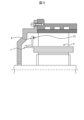
- FIG. 1 is an explanatory diagram of an installation position of a temperature sensor in a motor according to an embodiment of the present invention.
- FIG. 1(a) is an overall perspective view of a stator
- Fig. 1(b) is an enlarged view of a connection plate 18 in Fig. 1(a).
- the stator of a motor mounted on a vehicle has a stator core 2 and a plurality of coils 17.
- the plurality of coils 17 are electrically connected to the connection plate 18.
- the stator is held inside the motor housing, and the coils 17 are inserted into the slots of the stator core 2.
- the connection plate 18 is formed by molding the conductor 8 with a resin part 19, and has a number of welds 7.
- a clip 15 for attaching the temperature sensor to the conductor 8 is attached to the connection plate 18.
- the material of the conductor 8 is, for example, copper.
- the material of the clip 15 is, for example, stainless steel or ferrous spring steel.
- FIG. 2(a) is a diagram showing the clip 15 attached to the conductor 8
- Fig. 2(b) is an explanatory diagram of the configuration of the clip 15.
- the clip 15 has legs 15a, a housing part 15b, and a holding part 15c.
- the temperature sensor 12 is connected to a temperature sensor lead wire 12b covered with a temperature sensor glass tube 12a.
- the clip 15 is attached so that the temperature sensor 12 contacts the conductor 8 while holding the temperature sensor 12.
- the temperature sensor 12 measures the temperature of the stator core 2 via the conductor 8.
- the temperature sensor 12 is held by the holding portion 15c on the side opposite to the side that contacts the conductor 8, and the side of the temperature sensor 12 is covered by the housing portion 15b. Because the clip 15 has this structure, the temperature sensor 12 can ensure positional stability relative to the conductor 8.
- the legs 15a of the clip 15 are smaller in width, depth, and height than the housing 15b and the holding part 15c when the conductor 8 is used as the reference, so the space can be effectively utilized by engaging the legs 15a with the spatial insulation distance 20 with the cover 5 described below. This contributes to miniaturization.
- FIG. 3 Fig. 3(a) is a cross-sectional view showing the relationship between the temperature sensor 12 and the conductor 8
- Fig. 3(b) is an example of a different shape of the measured part 9 of Fig. 3(a). Note that only a part of the leg 15a of the clip 15 is shown in the figure.
- the clip 15 is attached to the conductor 8 by the legs 15a, and the temperature sensor 12 is fixed in contact with the conductor 8.
- the conductor 8 has a measurement part 9, which is the part whose temperature is measured by the temperature sensor 12.
- the measurement part 9 has a first surface 9a and a second surface 9b.
- the temperature sensor 12 is provided between the first surface 9a and one end surface 2a of the stator core 2.
- the first surface 9a has a temperature sensor 12 attached thereto and is in contact with the temperature sensor 12.
- the first surface 9a also faces one end surface 2a of the stator core 2 in the axial direction.
- the second surface 9b is the surface of the measured part 9 opposite the first surface 9a, and is engaged with the leg 15a of the clip 15.
- the conductor 8 When the conductor 8 is shaped by shearing, sagging and burrs (or burrs) are formed at each corner on the cross section. Therefore, when viewed in cross section, the measured part 9 has burrs 9d at each corner on the first surface 9a side and curved parts 9c with sagging shapes at each corner on the second surface 9b side.
- the clip 15 When the clip 15 is attached to the measured part 9, the legs 15a move to the second surface 9b side so as to trace the surface of the measured part 9 and are engaged by the curved parts 9c, thereby fixing the clip 15. In this way, the legs 15a are engaged by the curved parts 9c, making the process of engaging the clip 15 easier. Also, by not involving the burrs 9d in the engagement of the clip 15, the occurrence of contamination is suppressed and the welding can be stabilized.
- burr 9d side the contact surface during welding when welding the clip 15
- a large contact area can be secured between the measured part 9 and the clip 15, which promotes heat transfer between the conductors during welding and suppresses variation in the weld penetration depth.
- first surface 9a of the measured part 9 has a curved portion 9c on one side and a burr 9d on the other side.
- second surface 9b of the measured part 9 has a curved portion 9c on one side and a burr 9d on the other side.
- the conductor 8 may be formed by pressing or by forming a rectangular wire.
- the drooping shape of the curved portion 9c of the conductor 8 may be formed only on one corner of the first surface 9a or the second surface 9b of the leg 15a, or may be formed only on a part of the corner.
- the shaft 4 is provided with a resolver that detects the pole position and rotational speed of the rotor 3.
- the output from this resolver is input to a control circuit.
- the control circuit outputs a control signal to the drive circuit based on the input output information.
- the drive circuit outputs a drive signal based on the control signal to the power module.
- the power module performs switching operations based on the control signal, and converts the DC power supplied from the battery into three-phase AC power. This three-phase AC power is supplied to the stator windings, and a rotating magnetic field is generated in the stator.
- the frequency of the three-phase AC current is controlled based on the output value of the resolver, and the phase of the three-phase AC current relative to the rotor 3 is also controlled based on the output value of the resolver.
- the housing includes a first housing 13 and a second housing 14.
- the first housing 13 is for fixing the stator core 2 to the motor 100.
- the second housing 14 is for forming a refrigerant flow path 16 between the first housing 13 and the second housing 14.
- the conductor 8 is welded to the terminal of the coil 17 via the weld 7.
- the weld 7 is located on the opposite side of the conductor 8 in the axial direction from the installation position of the temperature sensor 12, which contributes to miniaturization.
- the temperature sensor 12 is positioned closer to the stator core 2, so the measured value of the temperature sensor 12 is closer to the true temperature of the stator core 2, and measurement errors can be reduced.
- the margin of temperature that should be taken into account in advance in control is reduced by the amount of error that has been reduced, making it possible to apply even larger power, which contributes to improving the output of the motor 100.
- the temperature sensor 12 may be attached to the measurement target 9 by other fasteners such as heat shrink tubing or adhesive without using the clip 15. This can reduce the number of parts.
- the measured portion 9 is a part of the conductor 8, but a part of the coil 17 may be extended and used as the measured portion 9. This eliminates the need to provide the conductor 8 that is welded to the coil 17, which contributes to reducing the number of parts.
- a stator for a rotating electric machine including a stator core 2, a coil 17 inserted into the stator core 2, a conductor 8 welded to the coil 17, a temperature sensor 12 that measures the temperature of the stator core 2 via the conductor 8, and a clip 15 for attaching the temperature sensor 12 to the conductor 8, in which the conductor 8 includes a welded portion 7 welded to a terminal of the coil 17 and a measured portion 9 that is measured by the temperature sensor 12.
- the measured portion 9 includes a first surface 9a to which the temperature sensor 12 is attached and a second surface 9b that is the surface opposite to the first surface 9a.
- the clip 15 includes a leg portion 15a that is engaged on the second surface 9b side and a holding portion 15c that holds the temperature sensor 12 on the first surface side 9a.
- the first surface 9a faces one end surface 2a of the stator core 2 in the axial direction, and the temperature sensor 12 is provided between the first surface 9a and the end surface 2a.
- the welded portion 7 is provided on the opposite side of the conductor 8 from the installation position of the temperature sensor 12 in the axial direction. This contributes to the miniaturization of the motor 100.
- the measurement target portion 9 When viewed in cross section, the measurement target portion 9 has curved portions 9c at each corner on the second surface 9b side. This makes it possible to suppress contamination and stabilize welding when the clip 15 is attached.
- the curved portion 9c is a drooping shape that is formed when the conductor 8 is sheared. This makes it possible to suppress contamination and stabilize welding when the clip 15 is assembled.
- the present invention is not limited to the above-described embodiment, and various modifications and other configurations can be combined without departing from the spirit of the invention. Furthermore, the present invention is not limited to those having all of the configurations described in the above-described embodiment, and also includes those in which some of the configurations have been omitted.
Landscapes
- Engineering & Computer Science (AREA)
- Microelectronics & Electronic Packaging (AREA)
- Power Engineering (AREA)
Priority Applications (3)
| Application Number | Priority Date | Filing Date | Title |
|---|---|---|---|
| JP2025527001A JPWO2024257271A1 (https=) | 2023-06-14 | 2023-06-14 | |
| CN202380094846.3A CN120752840A (zh) | 2023-06-14 | 2023-06-14 | 旋转电机的定子 |
| PCT/JP2023/022103 WO2024257271A1 (ja) | 2023-06-14 | 2023-06-14 | 回転電機の固定子 |
Applications Claiming Priority (1)
| Application Number | Priority Date | Filing Date | Title |
|---|---|---|---|
| PCT/JP2023/022103 WO2024257271A1 (ja) | 2023-06-14 | 2023-06-14 | 回転電機の固定子 |
Publications (1)
| Publication Number | Publication Date |
|---|---|
| WO2024257271A1 true WO2024257271A1 (ja) | 2024-12-19 |
Family
ID=93851543
Family Applications (1)
| Application Number | Title | Priority Date | Filing Date |
|---|---|---|---|
| PCT/JP2023/022103 Ceased WO2024257271A1 (ja) | 2023-06-14 | 2023-06-14 | 回転電機の固定子 |
Country Status (3)
| Country | Link |
|---|---|
| JP (1) | JPWO2024257271A1 (https=) |
| CN (1) | CN120752840A (https=) |
| WO (1) | WO2024257271A1 (https=) |
Citations (4)
| Publication number | Priority date | Publication date | Assignee | Title |
|---|---|---|---|---|
| JP2013121183A (ja) * | 2011-12-06 | 2013-06-17 | Toyota Motor Corp | 回転電機 |
| WO2019187570A1 (ja) * | 2018-03-30 | 2019-10-03 | 株式会社芝浦電子 | 温度検知装置および組付体 |
| WO2020026394A1 (ja) * | 2018-08-02 | 2020-02-06 | 株式会社芝浦電子 | 温度検知装置および組付体 |
| JP2021196170A (ja) * | 2020-06-09 | 2021-12-27 | 株式会社東芝 | 温度検出装置 |
-
2023
- 2023-06-14 CN CN202380094846.3A patent/CN120752840A/zh active Pending
- 2023-06-14 JP JP2025527001A patent/JPWO2024257271A1/ja active Pending
- 2023-06-14 WO PCT/JP2023/022103 patent/WO2024257271A1/ja not_active Ceased
Patent Citations (4)
| Publication number | Priority date | Publication date | Assignee | Title |
|---|---|---|---|---|
| JP2013121183A (ja) * | 2011-12-06 | 2013-06-17 | Toyota Motor Corp | 回転電機 |
| WO2019187570A1 (ja) * | 2018-03-30 | 2019-10-03 | 株式会社芝浦電子 | 温度検知装置および組付体 |
| WO2020026394A1 (ja) * | 2018-08-02 | 2020-02-06 | 株式会社芝浦電子 | 温度検知装置および組付体 |
| JP2021196170A (ja) * | 2020-06-09 | 2021-12-27 | 株式会社東芝 | 温度検出装置 |
Also Published As
| Publication number | Publication date |
|---|---|
| JPWO2024257271A1 (https=) | 2024-12-19 |
| CN120752840A (zh) | 2025-10-03 |
Similar Documents
| Publication | Publication Date | Title |
|---|---|---|
| CN103004059B (zh) | 无刷电机及其制造方法 | |
| CN108702052B (zh) | 定子、马达以及压缩机 | |
| CN102957270B (zh) | 马达 | |
| JP4688910B2 (ja) | 電動パワーステアリング装置用モータ | |
| JP5008742B2 (ja) | 電動式駆動装置 | |
| US7453179B2 (en) | DC brushless motor for electrical power steering and the production method thereof | |
| CN108604844B (zh) | 定子和旋转电机 | |
| JP5847543B2 (ja) | バスバーユニットおよびブラシレスモータ | |
| JP2002171708A (ja) | 回転電機 | |
| CN101682225A (zh) | 定子及使用该定子的旋转电机 | |
| JP2007014184A (ja) | 電気機械、電気機械のステータ構造及びその製造方法、並びに、直流モータ、特にブラシレス直流モータ | |
| JP2021164218A (ja) | モータおよび組み付け方法 | |
| US20190305650A1 (en) | Motor | |
| JP6184239B2 (ja) | 溶接構造および電動機 | |
| JP2021164220A (ja) | バスバーユニットおよびモータ | |
| CN112564424A (zh) | 汇流条单元和马达 | |
| JP2015012782A (ja) | モータ | |
| JP2021164221A (ja) | モータ | |
| KR101798919B1 (ko) | 회전전기기계 | |
| JP6229331B2 (ja) | モータ | |
| JP2007181314A (ja) | モータ | |
| WO2024257271A1 (ja) | 回転電機の固定子 | |
| US10958140B2 (en) | Motor | |
| JP6112983B2 (ja) | 回転電機 | |
| CN112787451A (zh) | 旋转电机以及旋转电机的制造方法 |
Legal Events
| Date | Code | Title | Description |
|---|---|---|---|
| 121 | Ep: the epo has been informed by wipo that ep was designated in this application |
Ref document number: 23941576 Country of ref document: EP Kind code of ref document: A1 |
|
| WWE | Wipo information: entry into national phase |
Ref document number: 202380094846.3 Country of ref document: CN |
|
| ENP | Entry into the national phase |
Ref document number: 2025527001 Country of ref document: JP Kind code of ref document: A |
|
| WWE | Wipo information: entry into national phase |
Ref document number: 2025527001 Country of ref document: JP |
|
| WWP | Wipo information: published in national office |
Ref document number: 202380094846.3 Country of ref document: CN |
|
| NENP | Non-entry into the national phase |
Ref country code: DE |