WO2024257260A1 - 光ケーブルの再利用システム - Google Patents
光ケーブルの再利用システム Download PDFInfo
- Publication number
- WO2024257260A1 WO2024257260A1 PCT/JP2023/022067 JP2023022067W WO2024257260A1 WO 2024257260 A1 WO2024257260 A1 WO 2024257260A1 JP 2023022067 W JP2023022067 W JP 2023022067W WO 2024257260 A1 WO2024257260 A1 WO 2024257260A1
- Authority
- WO
- WIPO (PCT)
- Prior art keywords
- optical cable
- component information
- reuse system
- sheath
- terminal
- Prior art date
- Legal status (The legal status is an assumption and is not a legal conclusion. Google has not performed a legal analysis and makes no representation as to the accuracy of the status listed.)
- Ceased
Links
Images
Classifications
-
- B—PERFORMING OPERATIONS; TRANSPORTING
- B29—WORKING OF PLASTICS; WORKING OF SUBSTANCES IN A PLASTIC STATE IN GENERAL
- B29B—PREPARATION OR PRETREATMENT OF THE MATERIAL TO BE SHAPED; MAKING GRANULES OR PREFORMS; RECOVERY OF PLASTICS OR OTHER CONSTITUENTS OF WASTE MATERIAL CONTAINING PLASTICS
- B29B17/00—Recovery of plastics or other constituents of waste material containing plastics
- B29B17/02—Separating plastics from other materials
- B29B2017/0213—Specific separating techniques
- B29B2017/0282—Specific separating techniques using information associated with the materials, e.g. labels on products
-
- B—PERFORMING OPERATIONS; TRANSPORTING
- B29—WORKING OF PLASTICS; WORKING OF SUBSTANCES IN A PLASTIC STATE IN GENERAL
- B29K—INDEXING SCHEME ASSOCIATED WITH SUBCLASSES B29B, B29C OR B29D, RELATING TO MOULDING MATERIALS OR TO MATERIALS FOR MOULDS, REINFORCEMENTS, FILLERS OR PREFORMED PARTS, e.g. INSERTS
- B29K2023/00—Use of polyalkenes or derivatives thereof as moulding material
- B29K2023/04—Polymers of ethylene
- B29K2023/06—PE, i.e. polyethylene
- B29K2023/0608—PE, i.e. polyethylene characterised by its density
- B29K2023/0633—LDPE, i.e. low density polyethylene
-
- B—PERFORMING OPERATIONS; TRANSPORTING
- B29—WORKING OF PLASTICS; WORKING OF SUBSTANCES IN A PLASTIC STATE IN GENERAL
- B29K—INDEXING SCHEME ASSOCIATED WITH SUBCLASSES B29B, B29C OR B29D, RELATING TO MOULDING MATERIALS OR TO MATERIALS FOR MOULDS, REINFORCEMENTS, FILLERS OR PREFORMED PARTS, e.g. INSERTS
- B29K2023/00—Use of polyalkenes or derivatives thereof as moulding material
- B29K2023/04—Polymers of ethylene
- B29K2023/06—PE, i.e. polyethylene
- B29K2023/0608—PE, i.e. polyethylene characterised by its density
- B29K2023/065—HDPE, i.e. high density polyethylene
-
- B—PERFORMING OPERATIONS; TRANSPORTING
- B29—WORKING OF PLASTICS; WORKING OF SUBSTANCES IN A PLASTIC STATE IN GENERAL
- B29L—INDEXING SCHEME ASSOCIATED WITH SUBCLASS B29C, RELATING TO PARTICULAR ARTICLES
- B29L2011/00—Optical elements, e.g. lenses, prisms
- B29L2011/0075—Light guides, optical cables
-
- G—PHYSICS
- G02—OPTICS
- G02B—OPTICAL ELEMENTS, SYSTEMS OR APPARATUS
- G02B6/00—Light guides; Structural details of arrangements comprising light guides and other optical elements, e.g. couplings
- G02B6/44—Mechanical structures for providing tensile strength and external protection for fibres, e.g. optical transmission cables
- G02B6/4479—Manufacturing methods of optical cables
- G02B6/4482—Code or colour marking
Definitions
- This disclosure relates to an optical cable reuse system.
- a recycler can obtain component information by accessing an external server using a device that the recycler owns.
- the tensile breaking elongation of the installation component tends to decrease.
- the ratio of optical cable sheaths reused in the installation component it is possible to prevent the tensile breaking elongation of the installation component from decreasing.
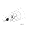
- Fig. 1 is a perspective view showing an example of an optical cable 1, a subduct 2, and a main duct 3 in which an optical cable 1 reuse system 100 according to an embodiment of the present disclosure is used.
- a subduct 2 is laid inside the main duct 3, and an optical cable 1 is further laid inside the subduct 2.
- one optical cable 1 is laid inside one subduct 2 in Fig. 1, a plurality of optical cables 1 may be laid inside one subduct 2.
- the optical cable 1 is, for example, a microduct cable that is laid inside the subduct 2 by air pressure or towing, and has an outer diameter of about 20 mm.
- the optical cable 1 includes a cable core 11 and an outer sheath 12 formed around the cable core 11.
- the cable core 11 includes an optical fiber ribbon 16 including a plurality of optical fiber cores 13, and an upper winding tape 14 that covers the plurality of optical fiber ribbons 16.
- the optical fiber cores 13 that make up the optical fiber ribbon 16 are, for example, intermittently connected to adjacent optical fiber cores 13 along the longitudinal direction of the optical cable 1. Note that although the optical cable 1 shown in FIG. 1 is a slotless type, it may be a slot type.
- the top winding tape 14 is wrapped around the multiple optical fiber ribbons 16 either vertically or spirally.
- the outer jacket 12 is formed by extrusion molding around the top winding tape 14.
- the outer jacket 12 is preferably formed from a material with a silicone additive amount in the range of 0.1% to 0.5% by mass. In this case, when the optical cable 1 is laid inside the subduct 2, the outer jackets 12 can be made slippery when they are in contact with each other or with the subduct 2, making it easier to lay the optical cable 1.
- a code 15 is attached to the outer cover 12.
- the code 15 is a QR code (registered trademark), which can record a large amount of information such as letters and numbers by combining white cells and black cells and can be read quickly.
- the code 15 stores component information of the jacket 12 of the optical cable 1.
- the component information includes the type of resin material contained in the jacket 12, such as high density polyethylene (HDPE) or low density polyethylene (LDPE), and the content of each type of resin material.
- the component information includes the type of additive contained in the jacket 12, such as carbon or silicone.
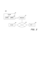
- FIG. 2 is a diagram showing a configuration of a reuse system 100 according to an embodiment of the present disclosure.
- the reuse system 100 includes a first terminal 30, a second terminal 40, and an external server 50.
- the first terminal 30 is communicatively connected to the second terminal 40 and the external server 50 via a wireless base station 61 and an external network 62 such as the Internet.
- the second terminal 40 is communicatively connected to the external server 50 via the external network 62.
- the first terminal 30 is, for example, a smartphone used by a worker who installs the optical cable 1, and includes an acquisition unit 31 equivalent to a smartphone camera, and a communication unit 32.
- the second terminal 40 is, for example, a PC (Personal Computer) used by a recycler.
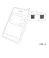
- Fig. 3 is a diagram showing an example of a method for reading the component information stored in the code 15 shown in Fig. 1.
- the codes 15 are attached to the jacket 12 of the optical cable 1 at multiple locations at predetermined intervals along the longitudinal direction of the optical cable 1.
- the predetermined intervals are, for example, within the range of 30 cm to 1 m.
- the worker uses the first terminal 30 to capture an image of one of the multiple cords 15.
- the acquisition unit 31 in the first terminal 30 acquires the component information stored in the cord 15.
- the worker acquires the component information stored in the cord 15 from the outer sheath 12 of the surplus optical cable 1, and performs an operation on the first terminal 30 to transmit the component information to the second terminal 40.
- the communication unit 32 in the first terminal 30 transmits the component information acquired by the acquisition unit 31 to the second terminal 40 via the wireless base station 61 and the external network 62.
- the second terminal 40 When the second terminal 40 receives the component information transmitted from the first terminal 30, it displays the content of the component information on the monitor of the second terminal 40, for example. This allows the recycler to accurately grasp the components of the jacket 12 of the optical cable 1 remaining after installation.
- the first terminal 30 may transmit the component information not only to the second terminal 40 but also to the external server 50.
- the code 15 stores the component information of the jacket 12 of the optical cable 1 as well as the ID (Identification) of the optical cable 1.
- the first terminal 30 can obtain the component information and ID stored in the code 15, associate the obtained component information with the ID, and store them in the external server 50.
- the second terminal 40 can also obtain the component information stored in the external server 50.
- a recycler performs an operation on the second terminal 40 to input the ID of the optical cable 1 and to request the acquisition of the component information of the jacket 12 of the optical cable 1.
- the second terminal 40 can obtain the component information corresponding to the input ID from the component information stored in the external server 50 and display the component information on a monitor or the like.
- the recycler can not only directly obtain the component information of the jacket 12 from the worker who lays the optical cable 1, but also obtain the component information of the jacket 12 stored in the external server 50 by accessing the external server 50 using the second terminal 40.
- the first terminal 30 is not limited to a smartphone, and may be AR (Argumented Reality) glasses or the like.
- a two-dimensional code or one-dimensional code other than a QR code may be attached as the code 15 to the outer sheath 12 of the optical cable 1.
- the component information stored in the code 15 is not limited to information indicating the components of the outer jacket 12 themselves, but may be identification information corresponding to the components of the outer jacket 12.
- the external server 50 stores a correspondence table indicating the correspondence between the components of the outer jacket 12 and the identification information.
- the second terminal 40 receives identification information from the first terminal 30 as the component information stored in the code 15, it can obtain the component corresponding to the identification information from the correspondence table stored in the external server 50.
- the recycler can accurately grasp the components of the jacket 12 of the optical cable 1, and therefore can more appropriately reuse the jacket 12.
- the recycler can take into consideration the type of resin material and the type of additives in the jacket 12 and more appropriately determine the mixing ratio and the destination of the jacket 12 when reusing the jacket 12.
- the outer jacket 12 of the optical cable 1 is reused, for example, as part of a laying component such as a duct in which another optical cable is laid. If the outer jacket 12 is reused as the outer jacket of another optical cable, the use of the reused outer jacket 12 may affect the characteristics of the other optical cable. In contrast, if the outer jacket 12 is reused as an installation component for the other optical cable as described above, it is possible to avoid affecting the characteristics of the other optical cable, and furthermore, the resin material contained in the outer jacket 12 can be effectively utilized.
- the proportion of the outer sheath 12 of the optical cable 1 in the installation component be 25% or less.
- the proportion of the outer sheath 12 of the optical cable 1 that is reused in the installation component it is possible to prevent the tensile breaking elongation of the installation component from becoming low.
Landscapes
- Engineering & Computer Science (AREA)
- Environmental & Geological Engineering (AREA)
- Mechanical Engineering (AREA)
- Light Guides In General And Applications Therefor (AREA)
Abstract
Description
光ケーブルに付され、前記光ケーブルの外被の成分情報が格納されたコードと、
前記成分情報を取得する取得部と、
前記光ケーブルの敷設後に前記成分情報を他の装置へ送信する通信部と、を備える。
ところで、光ケーブルの外被には、当該外被に含まれている樹脂材料の材料名が印字されていることがある。しかしながら、外被に印字されている材料名を確認するだけでは、外被に含まれる樹脂材料の種類や添加物等を十分に把握することができない可能性があり、外被の成分をより正確に把握することのできる技術が望まれている。
本開示によれば、光ケーブルの外被の成分をより正確に把握することができ、外被の再利用を適切に行うことができる。
最初に本開示の実施形態を列記して説明する。
本開示の実施形態に係る光ケーブルの再利用システムは、
(1)光ケーブルに付され、前記光ケーブルの外被の成分情報が格納されたコードと、
前記成分情報を取得する取得部と、
前記光ケーブルの敷設後に前記成分情報を他の装置へ送信する通信部と、を備える。
前記通信部は、前記成分情報を外部サーバに送信してもよい。
前記成分情報は、前記光ケーブルの外被に含まれる樹脂材料の種類を含んでもよい。
前記成分情報は、前記光ケーブルの外被に含まれる添加物の種類を含んでもよい。
前記光ケーブルの外被は、他の光ケーブルの敷設用部材に再利用されてもよい。
前記敷設用部材は、前記他の光ケーブルを内部に敷設するダクトであってもよい。
前記敷設用部材において再利用される前記光ケーブルの外被の割合は、25%以下であってもよい。
本開示の光ケーブルの再利用システムの具体例を、以下に図面を参照しつつ説明する。なお、本開示はこれらの例示に限定されるものではなく、請求の範囲によって示され、請求の範囲と均等の意味および範囲内でのすべての変更が含まれることが意図される。
図1は、本開示の実施形態に係る光ケーブル1の再利用システム100が用いられる光ケーブル1、サブダクト2およびメインダクト3の一例を示す斜視図である。図1に示すように、メインダクト3の内部にサブダクト2が敷設され、さらに、サブダクト2の内部に光ケーブル1が敷設される。図1では1つのサブダクト2の内部に1つの光ケーブル1が敷設されているが、1つのサブダクト2の内部に複数の光ケーブル1が敷設されてもよい。
図2は、本開示の実施形態に係る再利用システム100の構成を示す図である。図2を参照して、再利用システム100は、第1端末30と、第2端末40と、外部サーバ50とを備える。第1端末30は、無線基地局61、およびインターネットなどの外部ネットワーク62を介して、第2端末40および外部サーバ50との間で通信可能に接続されている。第2端末40は、外部ネットワーク62を介して外部サーバ50との間で通信可能に接続されている。
リサイクル業者において、上記のように、光ケーブル1の外被12の成分を正確に把握することができるため、当該外被12の再利用をより適切に行うことが可能となる。例えば、リサイクル業者は、外被12の樹脂材料の種類および添加物の種類を考慮して、当該外被12の再利用時における配合割合や再利用先などをより適切に決定することができる。
2 サブダクト
3 メインダクト
11 ケーブルコア
12 外被
13 光ファイバ心線
14 上巻きテープ
15 コード
16 光ファイバリボン
30 第1端末
31 取得部
32 通信部
40 第2端末
50 外部サーバ
61 無線基地局
62 外部ネットワーク
100 再利用システム
Claims (7)
- 光ケーブルに付され、前記光ケーブルの外被の成分情報が格納されたコードと、
前記成分情報を取得する取得部と、
前記光ケーブルの敷設後に前記成分情報を他の装置へ送信する通信部と、を備える、光ケーブルの再利用システム。 - 前記通信部は、前記成分情報を外部サーバに送信する、請求項1に記載の光ケーブルの再利用システム。
- 前記成分情報は、前記光ケーブルの外被に含まれる樹脂材料の種類を含む、請求項1または請求項2に記載の光ケーブルの再利用システム。
- 前記成分情報は、前記光ケーブルの外被に含まれる添加物の種類を含む、請求項1または請求項2に記載の光ケーブルの再利用システム。
- 前記光ケーブルの外被は、他の光ケーブルの敷設用部材に再利用される、請求項1または請求項2に記載の光ケーブルの再利用システム。
- 前記敷設用部材は、前記他の光ケーブルを内部に敷設するダクトである、請求項5に記載の光ケーブルの再利用システム。
- 前記敷設用部材において再利用される前記光ケーブルの外被の割合は、25%以下である、請求項5に記載の光ケーブルの再利用システム。
Priority Applications (3)
| Application Number | Priority Date | Filing Date | Title |
|---|---|---|---|
| JP2025526991A JPWO2024257260A1 (ja) | 2023-06-14 | 2023-06-14 | |
| PCT/JP2023/022067 WO2024257260A1 (ja) | 2023-06-14 | 2023-06-14 | 光ケーブルの再利用システム |
| EP23941565.6A EP4729264A4 (en) | 2023-06-14 | 2023-06-14 | OPTICAL CABLE REUSE SYSTEM |
Applications Claiming Priority (1)
| Application Number | Priority Date | Filing Date | Title |
|---|---|---|---|
| PCT/JP2023/022067 WO2024257260A1 (ja) | 2023-06-14 | 2023-06-14 | 光ケーブルの再利用システム |
Publications (1)
| Publication Number | Publication Date |
|---|---|
| WO2024257260A1 true WO2024257260A1 (ja) | 2024-12-19 |
Family
ID=93851581
Family Applications (1)
| Application Number | Title | Priority Date | Filing Date |
|---|---|---|---|
| PCT/JP2023/022067 Ceased WO2024257260A1 (ja) | 2023-06-14 | 2023-06-14 | 光ケーブルの再利用システム |
Country Status (3)
| Country | Link |
|---|---|
| EP (1) | EP4729264A4 (ja) |
| JP (1) | JPWO2024257260A1 (ja) |
| WO (1) | WO2024257260A1 (ja) |
Citations (8)
| Publication number | Priority date | Publication date | Assignee | Title |
|---|---|---|---|---|
| JP2001021730A (ja) * | 1999-07-07 | 2001-01-26 | Showa Electric Wire & Cable Co Ltd | 光ケーブルの布設関連情報管理方法 |
| JP2003241035A (ja) * | 1998-07-24 | 2003-08-27 | Nippon Telegr & Teleph Corp <Ntt> | 光ファイバコード及びこれを利用する集合型光ファイバコード |
| JP2004266886A (ja) * | 2003-02-12 | 2004-09-24 | Fujikura Ltd | Rfidを備えた連長体及びその製造方法、並びに連長体を使用した光ファイバケーブル |
| JP2005104128A (ja) * | 2003-09-12 | 2005-04-21 | Sanritsu Kikai Kogyo Kk | 光ファイバーケーブルのリサイクル方法および装置 |
| JP2005326656A (ja) | 2004-05-14 | 2005-11-24 | Sumitomo Electric Ind Ltd | 光ケーブルの解体方法及び解体装置 |
| JP2008074080A (ja) * | 2006-09-22 | 2008-04-03 | Kazuhisa Hanamiya | 電線屑リサイクル板 |
| JP2008112454A (ja) * | 2002-04-24 | 2008-05-15 | Teijin Fibers Ltd | リサイクルシステム |
| JP2022182777A (ja) * | 2021-05-28 | 2022-12-08 | 東洋インキScホールディングス株式会社 | リサイクル用包装材料と、包装材料のリサイクル方法及びリサイクルシステム |
Family Cites Families (6)
| Publication number | Priority date | Publication date | Assignee | Title |
|---|---|---|---|---|
| JP4914964B2 (ja) * | 2007-09-05 | 2012-04-11 | 株式会社ひたちなかテクノセンター | 多芯ケーブル結線管理方法とタグ製作方法及びその装置 |
| DE202013012003U1 (de) * | 2012-09-21 | 2015-02-03 | Egeplast International Gmbh | Rohr, insbesondere medienführendes Rohr oder Ummantelungsrohr |
| DE202013102180U1 (de) * | 2013-05-17 | 2014-08-18 | Kayhan Zirhlioglu | Identifizierbare Kabelummantelung |
| KR102014424B1 (ko) * | 2018-05-17 | 2019-08-26 | (주)우정넷 | 선번 확인이 가능한 광케이블시스템 |
| DE202019106920U1 (de) * | 2019-12-12 | 2021-03-15 | Rehau Ag + Co | Rohrbündel und Rohrsystem mit einem solchen Rohrbündel |
| US11328146B2 (en) * | 2020-07-28 | 2022-05-10 | Commscope Technologies Llc | Systems and methods for physical cable route tracing |
-
2023
- 2023-06-14 EP EP23941565.6A patent/EP4729264A4/en active Pending
- 2023-06-14 JP JP2025526991A patent/JPWO2024257260A1/ja active Pending
- 2023-06-14 WO PCT/JP2023/022067 patent/WO2024257260A1/ja not_active Ceased
Patent Citations (8)
| Publication number | Priority date | Publication date | Assignee | Title |
|---|---|---|---|---|
| JP2003241035A (ja) * | 1998-07-24 | 2003-08-27 | Nippon Telegr & Teleph Corp <Ntt> | 光ファイバコード及びこれを利用する集合型光ファイバコード |
| JP2001021730A (ja) * | 1999-07-07 | 2001-01-26 | Showa Electric Wire & Cable Co Ltd | 光ケーブルの布設関連情報管理方法 |
| JP2008112454A (ja) * | 2002-04-24 | 2008-05-15 | Teijin Fibers Ltd | リサイクルシステム |
| JP2004266886A (ja) * | 2003-02-12 | 2004-09-24 | Fujikura Ltd | Rfidを備えた連長体及びその製造方法、並びに連長体を使用した光ファイバケーブル |
| JP2005104128A (ja) * | 2003-09-12 | 2005-04-21 | Sanritsu Kikai Kogyo Kk | 光ファイバーケーブルのリサイクル方法および装置 |
| JP2005326656A (ja) | 2004-05-14 | 2005-11-24 | Sumitomo Electric Ind Ltd | 光ケーブルの解体方法及び解体装置 |
| JP2008074080A (ja) * | 2006-09-22 | 2008-04-03 | Kazuhisa Hanamiya | 電線屑リサイクル板 |
| JP2022182777A (ja) * | 2021-05-28 | 2022-12-08 | 東洋インキScホールディングス株式会社 | リサイクル用包装材料と、包装材料のリサイクル方法及びリサイクルシステム |
Non-Patent Citations (1)
| Title |
|---|
| See also references of EP4729264A4 |
Also Published As
| Publication number | Publication date |
|---|---|
| EP4729264A4 (en) | 2026-08-12 |
| EP4729264A1 (en) | 2026-04-22 |
| JPWO2024257260A1 (ja) | 2024-12-19 |
Similar Documents
| Publication | Publication Date | Title |
|---|---|---|
| US6185352B1 (en) | Optical fiber ribbon fan-out cables | |
| US9042693B2 (en) | Water-soluble water-blocking element | |
| US8380029B2 (en) | Fiber optic cable furcation methods and assemblies | |
| CN100498392C (zh) | 具有光波导的光纤制品、组件及电缆 | |
| US9176295B2 (en) | Stranded optical cable with connectors | |
| US6295401B1 (en) | Optical fiber ribbon cables | |
| JP2000195347A (ja) | 複合ケ―ブルユニット | |
| CN101770056A (zh) | 穿孔的阻水元件 | |
| WO2010065632A1 (en) | Optical fiber array cables and associated fiber optic cables and systems | |
| WO2003007043A1 (en) | Optical fiber cable for use in a dispersion managed cable system | |
| US6845200B1 (en) | Fiber optic assemblies, cable, and manufacturing methods therefor | |
| CA3104657A1 (en) | High density bundled optical fiber cable with preconnectorized drop points | |
| US20260066631A1 (en) | Information management system and information management method | |
| EP4403970A1 (en) | Optical fiber cable, optical fiber tape core, construction method of optical fiber cable, and optical transmission system | |
| EP4729264A1 (en) | Optical cable reuse system | |
| US20030016923A1 (en) | Dispersion managed fiber optic cable system with bridging path and marking methods therefor | |
| EP4227720A1 (en) | Optical cable | |
| JP2022187862A (ja) | 光ファイバ集合体の製造方法、光ファイバ集合体、及び、光ファイバ集合体の接続方法 | |
| WO2024134733A1 (ja) | 光ファイバケーブル、および光ファイバケーブルの情報管理方法 | |
| JP2010281966A (ja) | 光ケーブル、集合光ケーブル、及び光ケーブルの検出方法 | |
| JP2025011962A (ja) | 情報管理システムおよび情報管理方法 | |
| WO2024134732A1 (ja) | ケーブル、ケーブルの情報管理システムおよびケーブルの情報管理方法 | |
| EP3226047B1 (en) | Single layer optical fiber cable for microduct application | |
| JPH0331926Y2 (ja) | ||
| EP2466354A2 (en) | An optical fibre telecommunication cable |
Legal Events
| Date | Code | Title | Description |
|---|---|---|---|
| 121 | Ep: the epo has been informed by wipo that ep was designated in this application |
Ref document number: 23941565 Country of ref document: EP Kind code of ref document: A1 |
|
| ENP | Entry into the national phase |
Ref document number: 2025526991 Country of ref document: JP Kind code of ref document: A |
|
| WWE | Wipo information: entry into national phase |
Ref document number: 2025526991 Country of ref document: JP |
|
| WWE | Wipo information: entry into national phase |
Ref document number: 2023941565 Country of ref document: EP |
|
| NENP | Non-entry into the national phase |
Ref country code: DE |
|
| ENP | Entry into the national phase |
Ref document number: 2023941565 Country of ref document: EP Effective date: 20260114 |
|
| ENP | Entry into the national phase |
Ref document number: 2023941565 Country of ref document: EP Effective date: 20260114 |
|
| ENP | Entry into the national phase |
Ref document number: 2023941565 Country of ref document: EP Effective date: 20260114 |
|
| ENP | Entry into the national phase |
Ref document number: 2023941565 Country of ref document: EP Effective date: 20260114 |
|
| WWP | Wipo information: published in national office |
Ref document number: 2023941565 Country of ref document: EP |