WO2024257168A1 - 竪型遠心分離装置 - Google Patents
竪型遠心分離装置 Download PDFInfo
- Publication number
- WO2024257168A1 WO2024257168A1 PCT/JP2023/021748 JP2023021748W WO2024257168A1 WO 2024257168 A1 WO2024257168 A1 WO 2024257168A1 JP 2023021748 W JP2023021748 W JP 2023021748W WO 2024257168 A1 WO2024257168 A1 WO 2024257168A1
- Authority
- WO
- WIPO (PCT)
- Prior art keywords
- centrifugal separator
- vertical
- vertical centrifugal
- bottom plate
- separated liquid
- Prior art date
- Legal status (The legal status is an assumption and is not a legal conclusion. Google has not performed a legal analysis and makes no representation as to the accuracy of the status listed.)
- Ceased
Links
Images




Classifications
-
- B—PERFORMING OPERATIONS; TRANSPORTING
- B04—CENTRIFUGAL APPARATUS OR MACHINES FOR CARRYING-OUT PHYSICAL OR CHEMICAL PROCESSES
- B04B—CENTRIFUGES
- B04B1/00—Centrifuges with rotary bowls provided with solid jackets for separating predominantly liquid mixtures with or without solid particles
- B04B1/02—Centrifuges with rotary bowls provided with solid jackets for separating predominantly liquid mixtures with or without solid particles without inserted separating walls
-
- B—PERFORMING OPERATIONS; TRANSPORTING
- B04—CENTRIFUGAL APPARATUS OR MACHINES FOR CARRYING-OUT PHYSICAL OR CHEMICAL PROCESSES
- B04B—CENTRIFUGES
- B04B11/00—Feeding, charging, or discharging bowls
- B04B11/02—Continuous feeding or discharging; Control arrangements therefor
Definitions
- the present invention relates to a vertical centrifugal separator that separates the liquid being treated into solid and liquid.
- a centrifuge is a device that supplies the liquid to be treated inside a rotating bowl and applies centrifugal force to the liquid to perform separation operations according to the purpose, such as solid-liquid separation, liquid-liquid separation, or solid-liquid-liquid separation.
- Patent Document 1 discloses a vertical centrifuge apparatus that includes a cylindrical rotating cylinder that rotates around a vertical axis during centrifugation, with a supply port for the liquid to be treated formed at the bottom and a discharge port for the centrifuged separated liquid formed at the top, and a casing that houses the cylindrical rotating cylinder so that the cylindrical rotating cylinder can rotate around the vertical axis, a separated liquid collection chamber that has a circular opening formed in the bottom plate and whose inner periphery is located close to the outer periphery of the cylindrical rotating cylinder and is arranged to surround the entire orbit of the discharge port of the cylindrical rotating cylinder, a separated liquid collection cover that has a separated liquid discharge nozzle connected to the collection chamber and is arranged on the upper side of the casing, and one or more straightening blades that are arranged on the back surface of the bottom plate of the collection chamber and at least the surface on the rotation axis side of the cylindrical rotating cylinder is inclined inward, and the surface of the straightening blade is inclined so that the end
- this vertical centrifugal separator is to suppress the effects of swirling air currents generated by the high-speed rotation of the cylindrical rotating cylinder, and to prevent mist of separated liquid from leaking from the collection cover.
- a first object of the present invention is to prevent the separated liquid that has flowed into the collection chamber from overflowing.
- a second object of the present invention is to prevent the mist of separated liquid floating in the collection chamber from flowing out from the collection chamber toward the inside of the casing.
- the first configuration of the vertical centrifuge device is characterized in that (1) a cylindrical rotating cylinder having a supply port for the liquid to be treated formed at the bottom side and a discharge port for the centrifuged separated liquid formed at the top side, which rotates around a vertical axis when centrifuging, a casing in which the cylindrical rotating cylinder is housed so as to be rotatable around the vertical axis, a collection cover including a bottom plate portion having a circular opening through which the cylindrical rotating cylinder is inserted, the collection cover forming a collection chamber for the separated liquid communicating with the discharge port, and a discharge nozzle for the separated liquid connected to the collection chamber, the bottom plate portion of the collection chamber is inclined downward toward the outer periphery, and a dam portion including a vertical wall portion and a flange portion protruding from the upper end of the vertical wall portion toward the outer periphery of the bottom plate portion is provided at the edge of the circular opening of the bottom plate portion.
- the second configuration of the vertical centrifugal separator according to the present invention is characterized in that (2) an airflow generating unit that generates an airflow from the casing toward the circular opening is provided in the vertical centrifugal separator described above in (1).
- the first configuration of the present invention can prevent the separated liquid that has flowed into the collection chamber from overflowing and adhering to the back surface of the bottom plate of the collection cover (in other words, the first objective can be achieved).
- the second configuration of the present invention can further prevent the mist-like separated liquid floating in the collection chamber from flowing out of the collection chamber toward the inside of the casing (in other words, the first and second objectives can be achieved).
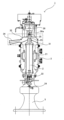
- FIG. 1 is a front view of a vertical centrifugal separator (first embodiment).
- FIG. 1 is a side view of a vertical centrifugal separator (first embodiment).
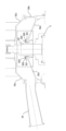
- FIG. FIG. 2 is an enlarged view of a portion of FIG.
- FIG. 5 is an enlarged view of a portion of FIG. 4 .
- FIG. 5 is an enlarged view of a portion of the vertical centrifugal separator of the first modified example, and corresponds to FIG. 4 .
- FIG. 5 is an enlarged view of a portion of the vertical centrifugal separator (second embodiment) and corresponds to FIG. 4 .
- FIG. 1 is a front view of a vertical centrifuge according to this embodiment, with the casing partially cut away.
- FIG. 2 is a side view of a vertical centrifuge according to this embodiment, with a partial perspective of the device.
- FIG. 3 is a plan view of a repair cover. This embodiment is a vertical centrifuge that achieves the first objective described in the "Objectives" section.
- the vertical centrifuge 1 comprises a bowl 2, which is a cylindrical rotating tube arranged in the vertical direction, a casing 3 as an exterior body that rotatably houses the bowl 2, a drive motor 4 as a drive device that generates power to rotate the bowl 2 around a vertical axis and perform centrifugation, and a support device 5 that supports these.
- the casing 3 has a casing body 31, and a collection cover 32 serving as an upper casing is removably attached to the top of the casing body 31.
- the collection cover 32 receives the separated liquid discharged from the upper side of the bowl 2 by the action of centrifugal force during centrifugation, and guides this separated liquid toward the discharge nozzle 34.
- a pipe (not shown) is removably connected to the tip of the discharge nozzle 34, and this pipe is connected to a storage tank (not shown).
- a pipe (not shown) is removably connected to the tip of the discharge nozzle 34, and this pipe is connected to a storage tank (not shown).
- the bowl 2 of the vertical centrifuge 1 in this embodiment is structured to separate the liquid to be treated into two phases, solid and liquid, but the present invention is not limited to this.
- the bowl 2 has a cylindrical body 21 with a hollow interior, with a supply port 22 for the liquid to be treated formed on the lower side and a separated liquid discharge port 23 for discharging the separated liquid formed on the upper side.
- a supply nozzle 24 for the liquid to be treated is inserted into a supply port 22 formed on the lower side of the bowl 2.
- the supply nozzle 24 is disposed away from the inner wall surface of the bowl 2. This makes it possible to prevent the inner wall surface of the bowl 2 from coming into contact with the supply nozzle 24 when the bowl 2 rotates.
- the liquid to be treated is delivered by a delivery means (not shown), such as a pump, and is discharged from the tip of the supply nozzle 24 and supplied into the bowl 2.
- a blade member e.g., a three-wing blade with three blades
- a blade member is arranged inside the bowl 2 to divide the internal space of the bowl 2 in the circumferential direction.
- the separated liquid is continuously discharged from the bowl 2, and the solids are accumulated in the bowl 2.
- the accumulated solids are collected after the vertical centrifuge 1 is stopped and the bowl 2 is removed from the casing 3.
- the vertical centrifuge 1 of this embodiment is a batch-type centrifuge.
- bowl 2 is not particularly limited, but as an example, the inner diameter is within the range of 95 to 160 mm, and the length is within the range of 457 to 730 mm.
- Bowl 2 is detachably connected to rotating shaft 26a of bearing assembly 26 by coupling nut 25, which is a detachment means.
- Bearing assembly 26 is connected to rotating pulley 42 of drive motor 4 through rotating belt 41.
- Bowl 2 is suspended and supported by connecting bowl 2 and bearing assembly 26 during centrifugation, and rotates about a vertical axis by power generated by drive motor 4.
- the connection between the bowl 2 and the bearing assembly 26 is released by releasing the connection by the coupling nut 25.
- FIG. 4 is an enlarged view of a portion of the vertical centrifugal separator, which is an enlargement of the area surrounded by the dotted line in Figure 1.
- Figure 5 is an enlarged view of a portion of the vertical centrifugal separator, which is an enlargement of the area surrounded by the dotted line in Figure 4.
- the collection cover 32 is composed of a bottom plate portion 32a, a side plate portion 32b, and a top surface portion 32c, and functions as a collection chamber for collecting the separated liquid obtained by the centrifugation.
- the separated liquid discharge port 23 is formed at a position facing this collection chamber.
- a circular opening 7 is formed in the center of the bottom plate portion 32a, and the tip (shaft) of the bowl 2 is inserted into this circular opening 7.
- the bottom plate portion 32a is formed in a tapered shape, and is inclined downward toward the outer periphery. By inclining the bottom plate portion 32a downward toward the outer periphery, a flow path can be formed that allows the separated liquid that flows in from the separated liquid discharge port 23 to flow toward the outer periphery. Because the circular opening 7 is formed in the center of the bottom plate portion 32a, the shape of the bottom plate portion 32a in a plan view is what is called a donut shape.
- a dam portion 320 is disposed in a ring shape on the edge of the circular opening 7 of the bottom plate portion 32a.
- the dam portion 320 includes a vertical wall portion 321 and a flange portion 322 that protrudes from the upper end of the vertical wall portion 321 toward the outer periphery of the bottom plate portion 32.
- the vertical wall portion 321 and the flange portion 322 are provided integrally with each other.
- the vertical wall portion 321 extends in the longitudinal direction (i.e., the up-down direction) of the bowl 2.
- the protruding direction of the flange portion 322 may be a direction perpendicular to the longitudinal axis of the bowl 2, or may be an inclined direction inclined with respect to the perpendicular direction.
- dam portion 320 By providing the dam portion 320 on the edge of the circular opening 7 of the bottom plate portion 32a, it is possible to prevent the separated liquid from overflowing from the circular opening 7 and leaking to the back side of the bottom plate portion 32a. Details of such an action and effect will be described later.
- the side plate portion 32b is formed to rise from the outer edge of the bottom plate portion 32a.
- a partial cutout portion is formed in the side plate portion 32b, and the discharge nozzle 34 is connected to this cutout portion.
- the bottom plate portion 32a and the side plate portion 32b can be formed integrally.
- Top surface portion 32c is attached to the upper end of side plate portion 32b and covers the upper opening of collection cover 32.
- top surface portion 32c is the upper lid of collection cover 32.
- the inner edge side of top surface portion 32c has a flat shape extending in a direction perpendicular to the longitudinal axis of bowl 2, and the outer edge side has an inclined shape that slopes toward the upper end of side plate portion 32b.
- top surface portion 32c is formed in a stepped shape.
- the inventors discovered that the separated liquid that flows into the collection chamber leaks out from the circular opening 7 by climbing over the vertical wall portion 321, and this leaked separated liquid (not in the form of a mist) adheres to the back surface side of the bottom plate portion 32a, etc.
- a swirling flow is generated by the rotation of the bowl 2, and it is presumed that this swirling flow causes the separated liquid to spread along the bottom plate portion 32a and climb over the vertical wall portion 321.
- overflow of the separated liquid can be prevented by providing a dam portion 320 consisting of a vertical wall portion 321 and a flange portion 322 on the edge of the circular opening 7. Whether or not the separated liquid has overflowed can be determined by visual inspection. If the separated liquid is found to be thickly attached when observing the back surface of the bottom plate portion 32a after centrifugation, it can be determined that the separated liquid has overflowed.
- the liquid to be treated is not particularly limited, but may include, for example, baker's yeast, baking soda, ink, cocoa mass, a mixture of minced chicken bones and fish, minced beef and pork, tea leaves, crosslinked acrylic polymer, collagen, saccharified grain (rice, barley, etc.), and vegetable pigment extract.
- the inventors have separately confirmed that when a separated liquid (e.g., ink pigment) with a surface tension smaller than that of water flows into the collection chamber, the separated liquid tends to spread along the bottom plate portion 32a. That is, even if airflow control is performed using a straightening blade (see Patent Document 1), the spreading phenomenon at the bottom plate portion 32a cannot be suppressed for a separated liquid with a surface tension smaller than that of water.
- the inventors have reviewed the means for solving the leakage of the separated liquid from scratch and discovered that a dam portion 320 is provided on the edge of the circular opening 7. Therefore, the vertical centrifugal separator of the first embodiment is more suitable for a separated liquid having a surface tension lower than that of water. However, it goes without saying that even for a separated liquid having a surface tension higher than that of water, the vertical wall portion 321 and the flange portion 322 cooperate to produce a dam effect.
- the height dimension W is preferably 10 mm or more, and the distance Z is preferably 2 mm or more.
- the height dimension W is preferably 10 mm or more, and the distance Z is preferably 2 mm or more.
- the height dimension W is preferably 10 mm or more, and the distance Z is preferably 2 mm or more.
- the dimensions W and the distance Z can be changed by adjusting the inclination angle of the bottom plate portion 32a. For example, if the inclination angle is made small in the design stage, the dimension W can be made longer.
- the clearance X is preferably 2.0 mm or more and 3.5 mm or less. If the clearance X is excessively small, there is a risk that the bowl 2 and the vertical wall portion 321 will come into contact during centrifugation. If the clearance X is excessively large, there is a risk that the separated liquid will leak out of the circular opening 7 when it flows from the separated liquid discharge port 23 into the collection chamber.
- the protruding length Y is preferably 5 mm or more. If the protruding length Y is too small, the dam effect of the flange 322 may be reduced. There is no particular upper limit to the protruding length Y, but if the protruding length Y is too long, the cleaning operation of the collection cover 32 may become complicated, and the separated liquid may stagnate on the flange 322 and be prevented from flowing into the collection chamber. Therefore, it is preferable that the protruding length Y be 15 mm or less.
- the centrifugal force of the bowl 2 is preferably 10,000 G or more, and more preferably 20,000 G or more.
- the liquid to be treated supplied to the bowl 2 is separated into two phases, solids and separated liquid, by centrifugal force and the difference in specific gravity.
- the solids accumulate on the inner surface of the bowl 2, and the separated liquid is discharged from the separated liquid discharge port 23 toward the collection chamber.
- the separated liquid that has flowed into the collection chamber is discharged from the discharge nozzle 34 along the tapered surface of the bottom plate portion 32a, but a part of the separated liquid remains in the collection chamber and spreads along the bottom plate portion 32a due to the action of the swirling flow.
- the separated liquid is blocked by the dam portion 320 consisting of the vertical wall portion 321 and the flange portion 322, so that the separated liquid can be prevented from overflowing from the circular opening 7.
- mist-like separated liquid may leak from the circular opening 7 and adhere to the wall surface of the casing body 31. Whether mist-like separated liquid has leaked or not can be determined by visual inspection. When the separated liquid is scattered in dots on the wall surface of the casing body 31, it can be determined that mist-like separated liquid has leaked.
- the dam portion 320 is configured by integrally forming the vertical wall portion 321 and the flange portion 322, but the present invention is not limited to this, and the vertical wall portion 321 and the flange portion 322 may be separate bodies.
- FIG. 6 is a cross-sectional view of a part of the vertical centrifugal separator of this modified example corresponding to FIG. 4.
- the dam portion 320 is composed of the vertical wall portion 321 and the ring-shaped flange portion 323.
- the ring-shaped flange portion 323 is composed of a flange portion main body 323a and a leg portion 323b, which are integrally formed.
- the leg portion 323b is formed in a ring shape and is in pressure contact with the surface on the outer circumferential side of the vertical wall portion 321.
- the flange portion main body 323a is provided at the upper end of the leg portion 323b and protrudes toward the outer circumferential side of the bottom plate portion 32a.
- the vertical wall portion 321 and the ring-shaped flange portion 323 of this modified example also provide the above-mentioned dam effect.
- the collecting chamber formed by the collecting cover 32 has a single stage, but the present invention is not limited to this and may have a two-stage structure (see, for example, Patent Document 1).
- the lower stage side is the heavy liquid collecting chamber and the upper stage side is the light liquid collecting chamber, and a dam portion can be provided on the edge of the circular opening of the bottom plate portion of at least one of the heavy liquid collecting chamber and the light liquid collecting chamber.
- Second Embodiment Fig. 7 is an enlarged view of a part of the vertical centrifugal separator of this embodiment, corresponding to Fig. 4.
- the direction of the airflow generated by the flow straightening blades is typically indicated by dashed arrows.
- This embodiment relates to a vertical centrifugal separator that achieves both the first and second objects described in the "Objectives" section.
- the separated liquid that flows into the collection chamber collides with the inner wall of the collection cover 32, and some of the separated liquid turns into mist. Although it is only a small amount, the mist-like separated liquid may be drawn into the swirling flow in the collection chamber and leak from the circular opening 7 toward the casing body 31. This problem is described in Patent Document 1, paragraphs 0007 to 0008, and so details will be omitted.
- a plurality of straightening vanes 51 are disposed on the rear surface of the bottom plate portion 32a. If the surface of the straightening vanes 51 is inclined inward, it is possible to generate an airflow that causes the air drawn into the casing body 31 from the supply nozzle 24 to flow toward the circular opening 7, i.e., an upward airflow, when the vertical centrifugal separator is operated.
- the structure of the straightening vanes 51 that achieves this effect is a conventional technique as disclosed in, for example, Patent Document 1, and therefore a detailed description thereof will be omitted.
- the airflow generating section is realized by the straightening blades 51, but the present invention is not limited to this.
- an upward airflow toward the circular opening 7 may be forcibly generated by blowing air from the supply nozzle 24 toward the inside of the casing body 31 using a blowing means such as a blower (corresponding to the "airflow generating section").
- the air generated by the airflow generating section can be taken in approximately evenly from the entire circumference of the circular opening 7.
- the protruding length Y of the flange 322 can be set to 5 mm or more, a portion of the air taken in through the circular opening 7 can be made to flow along the flange 322.
- leakage of the mist-like separated liquid can be more effectively prevented.
- the other dimensional conditions of W, X, Y, and Z described in the first embodiment can also be applied to this embodiment. Needless to say, the configurations of the above-mentioned modified examples 1 and 2 can also be applied to this embodiment.
Landscapes
- Centrifugal Separators (AREA)
Priority Applications (2)
| Application Number | Priority Date | Filing Date | Title |
|---|---|---|---|
| PCT/JP2023/021748 WO2024257168A1 (ja) | 2023-06-12 | 2023-06-12 | 竪型遠心分離装置 |
| JP2025526917A JPWO2024257168A1 (https=) | 2023-06-12 | 2023-06-12 |
Applications Claiming Priority (1)
| Application Number | Priority Date | Filing Date | Title |
|---|---|---|---|
| PCT/JP2023/021748 WO2024257168A1 (ja) | 2023-06-12 | 2023-06-12 | 竪型遠心分離装置 |
Publications (1)
| Publication Number | Publication Date |
|---|---|
| WO2024257168A1 true WO2024257168A1 (ja) | 2024-12-19 |
Family
ID=93851472
Family Applications (1)
| Application Number | Title | Priority Date | Filing Date |
|---|---|---|---|
| PCT/JP2023/021748 Ceased WO2024257168A1 (ja) | 2023-06-12 | 2023-06-12 | 竪型遠心分離装置 |
Country Status (2)
| Country | Link |
|---|---|
| JP (1) | JPWO2024257168A1 (https=) |
| WO (1) | WO2024257168A1 (https=) |
Citations (4)
| Publication number | Priority date | Publication date | Assignee | Title |
|---|---|---|---|---|
| US2719668A (en) * | 1952-09-04 | 1955-10-04 | Separator Ab | Centrifugal bowl |
| JPS53105767A (en) * | 1977-02-23 | 1978-09-14 | Kloeckner Humboldt Deutz Ag | Centrifugal separator for mixture* especially for molten metal* metal compound and * or metallcontaining sludge |
| JPS59180747U (ja) * | 1983-05-20 | 1984-12-03 | 三井造船株式会社 | 遠心式フイルタ |
| JP2013000652A (ja) * | 2011-06-16 | 2013-01-07 | Tomoe Engineering Co Ltd | 竪型遠心分離装置 |
-
2023
- 2023-06-12 JP JP2025526917A patent/JPWO2024257168A1/ja active Pending
- 2023-06-12 WO PCT/JP2023/021748 patent/WO2024257168A1/ja not_active Ceased
Patent Citations (4)
| Publication number | Priority date | Publication date | Assignee | Title |
|---|---|---|---|---|
| US2719668A (en) * | 1952-09-04 | 1955-10-04 | Separator Ab | Centrifugal bowl |
| JPS53105767A (en) * | 1977-02-23 | 1978-09-14 | Kloeckner Humboldt Deutz Ag | Centrifugal separator for mixture* especially for molten metal* metal compound and * or metallcontaining sludge |
| JPS59180747U (ja) * | 1983-05-20 | 1984-12-03 | 三井造船株式会社 | 遠心式フイルタ |
| JP2013000652A (ja) * | 2011-06-16 | 2013-01-07 | Tomoe Engineering Co Ltd | 竪型遠心分離装置 |
Also Published As
| Publication number | Publication date |
|---|---|
| JPWO2024257168A1 (https=) | 2024-12-19 |
Similar Documents
| Publication | Publication Date | Title |
|---|---|---|
| JP2008540908A (ja) | クランクハウジングを排気する際にガスを浄化する装置 | |
| KR101571302B1 (ko) | 분리액 분사노즐을 구비한 원심분리기 | |
| CA2246173C (en) | Flotation cells with devices to enhance recovery of froth containing mineral values | |
| US20230415170A1 (en) | Separator having a removable centrifuge container | |
| JPH0753955B2 (ja) | ガス排出装置 | |
| KR100623114B1 (ko) | 분리 장치 | |
| US2881974A (en) | Centrifuge | |
| WO2024257168A1 (ja) | 竪型遠心分離装置 | |
| US6740027B1 (en) | Solid bowl centrifuge with liquid release during rotation | |
| JP3532569B2 (ja) | 液体分離装置 | |
| US20250114801A1 (en) | Discharge device for a reaction vessel unit, centrifuge and method for cleaning a reaction vessel unit | |
| CN216459471U (zh) | 一种下卸料离心机 | |
| US5823937A (en) | Low-shear feeding system for use with centrifuges | |
| JP5710905B2 (ja) | 遠心分離機 | |
| WO1997016256A9 (en) | Low-shear centrifuge feeding system | |
| JPH11318397A (ja) | 生海苔洗浄機及び生海苔洗浄方法 | |
| JP4489482B2 (ja) | 海苔混合液の異物分離装置における液位を基準値とした回転部の回転制御方法 | |
| JP3647939B2 (ja) | 排水ポンプ | |
| CN117046214A (zh) | 气化灰水分离装置 | |
| US7118521B2 (en) | Centrifugal separator with conical pump inlet | |
| JPH0953591A (ja) | 排水ポンプ | |
| JP7630869B1 (ja) | 分離装置及び分離方法 | |
| EP0876555B1 (en) | Improvements in an unloading pump which is submersible in the cargo of a ship's cargo tank | |
| JP2000126508A (ja) | 真空脱泡機 | |
| KR101626211B1 (ko) | 물과 슬러지를 분리하는 원심분리기 |
Legal Events
| Date | Code | Title | Description |
|---|---|---|---|
| 121 | Ep: the epo has been informed by wipo that ep was designated in this application |
Ref document number: 23940939 Country of ref document: EP Kind code of ref document: A1 |
|
| WWE | Wipo information: entry into national phase |
Ref document number: 2025526917 Country of ref document: JP |
|
| NENP | Non-entry into the national phase |
Ref country code: DE |