WO2024253184A1 - 医療用デバイス - Google Patents
医療用デバイス Download PDFInfo
- Publication number
- WO2024253184A1 WO2024253184A1 PCT/JP2024/020846 JP2024020846W WO2024253184A1 WO 2024253184 A1 WO2024253184 A1 WO 2024253184A1 JP 2024020846 W JP2024020846 W JP 2024020846W WO 2024253184 A1 WO2024253184 A1 WO 2024253184A1
- Authority
- WO
- WIPO (PCT)
- Prior art keywords
- jaw
- base end
- power line
- medical device
- cylindrical body
- Prior art date
- Legal status (The legal status is an assumption and is not a legal conclusion. Google has not performed a legal analysis and makes no representation as to the accuracy of the status listed.)
- Ceased
Links
Images





Classifications
-
- A—HUMAN NECESSITIES
- A61—MEDICAL OR VETERINARY SCIENCE; HYGIENE
- A61B—DIAGNOSIS; SURGERY; IDENTIFICATION
- A61B18/00—Surgical instruments, devices or methods for transferring non-mechanical forms of energy to or from the body
- A61B18/04—Surgical instruments, devices or methods for transferring non-mechanical forms of energy to or from the body by heating
- A61B18/12—Surgical instruments, devices or methods for transferring non-mechanical forms of energy to or from the body by heating by passing a current through the tissue to be heated, e.g. high-frequency current
- A61B18/14—Probes or electrodes therefor
- A61B18/1442—Probes having pivoting end effectors, e.g. forceps
- A61B18/1445—Probes having pivoting end effectors, e.g. forceps at the distal end of a shaft, e.g. forceps or scissors at the end of a rigid rod
- A61B18/1447—Probes having pivoting end effectors, e.g. forceps at the distal end of a shaft, e.g. forceps or scissors at the end of a rigid rod wherein sliding surfaces cause opening/closing of the end effectors
-
- A—HUMAN NECESSITIES
- A61—MEDICAL OR VETERINARY SCIENCE; HYGIENE
- A61B—DIAGNOSIS; SURGERY; IDENTIFICATION
- A61B18/00—Surgical instruments, devices or methods for transferring non-mechanical forms of energy to or from the body
- A61B18/04—Surgical instruments, devices or methods for transferring non-mechanical forms of energy to or from the body by heating
- A61B18/12—Surgical instruments, devices or methods for transferring non-mechanical forms of energy to or from the body by heating by passing a current through the tissue to be heated, e.g. high-frequency current
- A61B18/14—Probes or electrodes therefor
-
- A—HUMAN NECESSITIES
- A61—MEDICAL OR VETERINARY SCIENCE; HYGIENE
- A61B—DIAGNOSIS; SURGERY; IDENTIFICATION
- A61B18/00—Surgical instruments, devices or methods for transferring non-mechanical forms of energy to or from the body
- A61B18/04—Surgical instruments, devices or methods for transferring non-mechanical forms of energy to or from the body by heating
- A61B18/12—Surgical instruments, devices or methods for transferring non-mechanical forms of energy to or from the body by heating by passing a current through the tissue to be heated, e.g. high-frequency current
- A61B18/14—Probes or electrodes therefor
- A61B18/1442—Probes having pivoting end effectors, e.g. forceps
- A61B18/1445—Probes having pivoting end effectors, e.g. forceps at the distal end of a shaft, e.g. forceps or scissors at the end of a rigid rod
-
- A—HUMAN NECESSITIES
- A61—MEDICAL OR VETERINARY SCIENCE; HYGIENE
- A61B—DIAGNOSIS; SURGERY; IDENTIFICATION
- A61B17/00—Surgical instruments, devices or methods
- A61B17/28—Surgical forceps
- A61B17/29—Forceps for use in minimally invasive surgery
- A61B2017/2926—Details of heads or jaws
- A61B2017/2932—Transmission of forces to jaw members
- A61B2017/2933—Transmission of forces to jaw members camming or guiding means
- A61B2017/2936—Pins in guiding slots
-
- A—HUMAN NECESSITIES
- A61—MEDICAL OR VETERINARY SCIENCE; HYGIENE
- A61B—DIAGNOSIS; SURGERY; IDENTIFICATION
- A61B17/00—Surgical instruments, devices or methods
- A61B17/28—Surgical forceps
- A61B17/29—Forceps for use in minimally invasive surgery
- A61B2017/2947—Pivots
-
- A—HUMAN NECESSITIES
- A61—MEDICAL OR VETERINARY SCIENCE; HYGIENE
- A61B—DIAGNOSIS; SURGERY; IDENTIFICATION
- A61B18/00—Surgical instruments, devices or methods for transferring non-mechanical forms of energy to or from the body
- A61B2018/00053—Mechanical features of the instrument of device
- A61B2018/00172—Connectors and adapters therefor
- A61B2018/00178—Electrical connectors
-
- A—HUMAN NECESSITIES
- A61—MEDICAL OR VETERINARY SCIENCE; HYGIENE
- A61B—DIAGNOSIS; SURGERY; IDENTIFICATION
- A61B18/00—Surgical instruments, devices or methods for transferring non-mechanical forms of energy to or from the body
- A61B2018/00571—Surgical instruments, devices or methods for transferring non-mechanical forms of energy to or from the body for achieving a particular surgical effect
- A61B2018/00601—Cutting
-
- A—HUMAN NECESSITIES
- A61—MEDICAL OR VETERINARY SCIENCE; HYGIENE
- A61B—DIAGNOSIS; SURGERY; IDENTIFICATION
- A61B18/00—Surgical instruments, devices or methods for transferring non-mechanical forms of energy to or from the body
- A61B2018/00571—Surgical instruments, devices or methods for transferring non-mechanical forms of energy to or from the body for achieving a particular surgical effect
- A61B2018/00607—Coagulation and cutting with the same instrument
Definitions
- the present invention relates to a medical device that has a first jaw and a second jaw that can be opened and closed, and that holds biological tissue between the two jaws when they are in a closed state.
- a blood vessel that bypasses the diseased area is connected to the artery.
- This blood vessel is harvested, for example, from the patient's leg using an endoscopic blood vessel harvesting system.
- the endoscopic blood vessel harvesting system includes a medical device equipped with a blood vessel harvesting tool.
- the medical device may have a configuration having a first jaw and a second jaw that can be opened and closed.
- a first electrode is provided on the first jaw
- a second electrode is provided on the second jaw.
- the tip of a power line is connected to each of the first electrode and the second electrode in order to pass electricity through the first electrode and the second electrode.
- the power line may be pushed by the edge of the rotating one of the first jaw and the second jaw and pulled toward the tip.
- the power line is placed under tension.
- the present invention aims to solve the above-mentioned problems.
- An aspect of the present invention is a medical device comprising a first jaw and a second jaw that can be opened and closed and that sandwich biological tissue between them when in a closed state, and at least the second jaw is rotatable, the first jaw having a first support portion, a first base end portion connected to the base end side of the first support portion, a first main body portion supported by the first support portion, and a first electrode supported by the first support portion, the second jaw having a second support portion, a second base end portion connected to the base end side of the second support portion, a second main body portion supported by the second support portion, and a first electrode supported by the second support portion.
- the first base end having a first inner surface and a first outer surface that is the reverse side of the first inner surface
- the second base end having a second inner surface that faces the first inner surface when the first jaw and the second jaw are in a closed state and a second outer surface that is the reverse side of the second inner surface
- the medical device comprising a first power line electrically connected to the first electrode and a second power line electrically connected to the second electrode, at least a portion of the first power line being disposed along the first outer surface.
- the biological tissue in the present invention includes a biological organ that is an aggregate of biological tissue.
- the first power line passes outside the first base end, when the first jaw and the second jaw change from a closed state to an open state, the first power line is prevented from being pushed by the edge of the second base end of the rotating second jaw and pulled toward the tip. Therefore, tension is prevented from being applied to the first power line.
- the medical device described in item (1) above may include a rotating shaft that serves as the center of rotation of the second jaw, and the portion of the first power line that is proximal to the rotating shaft may be disposed along the first outer surface.
- This configuration further prevents the first power line from being pulled toward the tip when the first jaw and the second jaw change from a closed state to an open state.
- the first support portion has a first support surface that extends in a first axial direction, which is the longitudinal direction of the first support portion, and in a first width direction perpendicular to the first axial direction, and supports the first main body portion.
- first support portion is divided into a first connected portion and a first non-connected portion based on a first straight line that is parallel to the first axial direction and bisects the first support surface along the first width direction
- the first base end portion is connected to the base end of the first connected portion, and the first support portion may have a first notch formed in the first connected portion and through which the first power line is passed.
- the device includes a rotating shaft that is the center of rotation of the second jaw, and a first cylindrical body that supports the first jaw and the second jaw via the rotating shaft, the first cylindrical body has a first extension portion that extends from the tip of the first cylindrical body and supports the second jaw via the rotating shaft, and when the first extension portion is cut along a direction perpendicular to the axial direction of the first cylindrical body, the first power line may be in contact with the inside of the outer contour line of the first cylindrical body that appears on the cut surface of the first extension portion, or may be located inside the outer contour line.
- the first power line By positioning the first power line as described above, the first power line can be housed inside the first cylindrical body.
- the medical device described in item (4) above may include a second cylindrical body that is housed inside the first cylindrical body and moves relative to the first cylindrical body to rotate the second jaw, the second cylindrical body having a second extension portion that extends from the tip of the second cylindrical body and overlaps the first extension portion inside the first extension portion, and when the first extension portion and the second extension portion are cut along a direction perpendicular to the axial direction of the first cylindrical body and the second cylindrical body, the first power line may be located in a first space formed by the first extension portion, the second extension portion, the outer contour line, and the first base end.
- the first power line By positioning the first power line as described above, the first power line can be housed in the first space formed between the first cylinder and the second cylinder.
- the second extension portion has an inner surface facing the first base end, an outer surface facing the first extension portion, and a side surface that is connected to the inner surface and the outer surface and extends along the axial direction of the second extension portion, and when the second extension portion is viewed from the axial direction of the second cylindrical body, the side surface may be parallel to the axis of the rotating shaft.
- the side surface is parallel to the axis of the rotating shaft.
- the capacity of the first space is larger than when the side surface is curved in an arc. Therefore, it is easy to accommodate the first power line between the first cylinder and the second cylinder.
- the first outer surface of the first base end may have a first groove extending along the axial direction of the first base end and into which the first power line is inserted.
- the space for accommodating the first power line can be narrowed. This allows the medical device to be made smaller.
- the first base end may have a penetration portion that opens at the first inner surface and the first outer surface and through which the first power line passes, and the first power line may be disposed along the first inner surface distal to the penetration portion and disposed along the first outer surface proximal to the penetration portion.
- the first power line is further prevented from being pulled toward the tip when the first jaw and the second jaw change from a closed state to an open state.
- a rotating shaft is provided as a center of rotation for the second jaw, the first jaw is rotatable around the rotating shaft, and at least a portion of the second power line may be arranged along the second outer surface.
- the second power line Since at least a portion of the second power line passes outside the second base end, when the first jaw and the second jaw change from a closed state to an open state, the second power line is prevented from being pushed by the edge of the first base end and pulled by the tip end. Therefore, tension is prevented from being applied to the second power line.
- the shape and position of the second support part and the second base end part have a rotationally symmetric relationship with the shape and position of the first support part and the first base end part, and the second power line may be disposed in a position that is rotationally symmetric with the first power line.
- This configuration allows the second jaw to achieve the same effect as the first jaw described above.
- the first power line is prevented from being pushed by the edge of the second base end of the rotating second jaw and pulled in the tip direction. This prevents tension from being applied to the first power line.
- FIG. 1 is a perspective view of a main portion of a medical device.
- FIG. 2 is a perspective view of a main part of the medical device, with the first cylindrical body not shown.
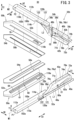
- FIG. 3 is an exploded perspective view of a collection tool constituting the medical device.
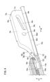
- FIG. 4 is a sectional perspective view of a main portion of the first jaw.
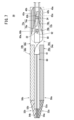
- FIG. 5 is a schematic cross-sectional view of the proximal end side of the medical device taken along a direction perpendicular to the axial direction of the first cylindrical body, looking from the proximal end side to the distal end side.
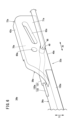
- FIG. 6 is a perspective view of a main portion of a first jaw according to a modified example.
- FIG. 1 is a perspective view of a main portion of a medical device.
- FIG. 2 is a perspective view of a main part of the medical device, with the first cylindrical body not shown.
- FIG. 3 is an exploded perspective view of a collection tool constituting the medical device.
- FIG. 7 is a schematic cross-sectional side view of the collection device in a closed position.
- FIG. 8 is a schematic cross-sectional side view of the harvesting device in a closed state with the cutter advanced.
- FIG. 9 is a schematic cross-sectional side view of the collection device in an open position.
- tip refers to the direction of each component that approaches the biological tissue when the biological tissue is harvested.
- base refers to the direction opposite to the tip of each component.
- first clamping portion 50a is located relatively closer to the tip side than the first base end portion 38a.
- the first base end portion 38a is located relatively closer to the base end side than the first clamping portion 50a.
- both the first jaw 32a and the second jaw 32b are rotatable around the rotating shaft 22.
- the positions and shapes of the first jaw 32a and the second jaw 32b are basically rotationally symmetrical with respect to the center of symmetry O shown in FIG. 5.
- the "first" in the names of the components of the first jaw 32a is replaced with "second”.
- the alphabet "a" in the reference symbols of the components of the first jaw 32a is replaced with "b" as a general rule. Note that detailed descriptions of the components of the second jaw 32b may be omitted.
- Opening and closing the collection tool 30 is synonymous with “opening and closing the first jaw 32a and the second jaw 32b.”
- the collection tool 30 is in an open state is synonymous with “the first jaw 32a and the second jaw 32b are in an open state”
- the collection tool 30 is in a closed state is synonymous with “the first jaw 32a and the second jaw 32b are in a closed state.”
- the present invention is not limited to the above embodiment.
- the first jaw 32a may be fixed so that it cannot rotate, and only the second jaw 32b may be rotatable.
- the first extension portion 132 of the first cylindrical body 130 and the second extension portion 16 of the second cylindrical body 12 do not need to be a pair, and each may be one. Even in this case, the collection device 30 opens and closes as the second jaw 32b rotates.
- biological tissue in the present invention includes biological organs.
- An example of a biological organ is a hollow organ.
- An example of a hollow organ is the digestive tract, ureter, trachea, cervical canal, etc.
- FIG. 1 is a perspective view of the main parts of a medical device 10 according to this embodiment.
- the medical device 10 comprises a first cylindrical body 130, a second cylindrical body 12, and a collection tool 30.
- the first cylindrical body 130 and the second cylindrical body 12 are tubular members that extend linearly along the axial direction.
- the first cylindrical body 130 and the second cylindrical body 12 are cylindrical in shape, but they may also be polygonal cylindrical in shape.
- the first cylindrical body 130 has a pair of first extending portions 132.
- the pair of first extending portions 132 extend from the tip of the first cylindrical body 130 along the axial direction of the first cylindrical body 130.
- the outer surface and inner surface of the pair of first extending portions 132 are a curved outer surface 133 and a curved inner surface 135 (see FIG. 5), respectively.
- a flat side surface 137 is continuous with the curved outer surface 133 and the curved inner surface 135.
- a pair of first notched grooves 134 are formed between the pair of first extending portions 132 (see FIG. 1).
- the pair of first notched grooves 134 are positioned 180° apart from each other in the circumferential direction.
- the pair of first notched grooves 134 extend along the axial direction of the first cylindrical body 130.
- a pair of support holes 136 are formed in each of the pair of first extension portions 132.
- the axial direction of the support holes 136 is perpendicular to the axial direction of the first cylindrical body 130.
- the support holes 136 penetrate from the curved outer surface 133 to the curved inner surface 135 of the first extension portion 132.
- the center positions of the pair of support holes 136 are shifted by 90° in the circumferential direction of the first cylindrical body 130 from the centers of the pair of first notch grooves 134.
- Both axial ends of the rotating shaft 22, which will be described later, are fitted into the pair of support holes 136, respectively. Based on this fit, the rotating shaft 22 is positioned and fixed relative to the first cylindrical body 130.
- a jaw operating section a cutter operating section, an energizing switch, and the like are provided at the base end of the first cylinder 130.
- the hollow interior of the first cylinder 130 accommodates, for example, a first power line 120a and a second power line 120b that carry high-frequency current.
- the second cylinder body 12 is shorter than the first cylinder body 130, and is housed in the hollow interior at the tip of the first cylinder body 130. As the operator operates the jaw operating portion, power is transmitted to the second cylinder body 12 via a power transmission member (not shown). As a result, the second cylinder body 12 moves within the first cylinder body 130. In this way, the second cylinder body 12 is housed movably within the first cylinder body 130.
- the second cylindrical body 12 has a pair of second extending portions 16.
- the pair of second extending portions 16 extend from the tip of the second cylindrical body 12 along the axial direction of the second cylindrical body 12.
- the outer surface 15 and the inner surface 17 of the pair of second extending portions 16 are curved surfaces (see FIG. 5).
- Each of the pair of second extending portions 16 has a pair of side surfaces 19 that are connected to the outer surface 15 and the inner surface 17 and extend along the axial direction of the second extending portion 16.
- the outer surface 15 may be in sliding contact with the curved inner surface 135 of the first cylindrical body 130.
- a pair of second notch grooves 14 are formed between the pair of second extension portions 16.
- the pair of second notch grooves 14 are arranged at positions spaced 180° apart from each other in the circumferential direction.
- the pair of second notch grooves 14 extend along the axial direction of the second cylindrical body 12.
- the pair of second extension portions 16 are covered by the pair of first extension portions 132.
- the pair of second notch grooves 14 overlap the pair of first notch grooves 134.
- a pair of guide grooves 18 and a pair of pin mounting holes 20 are formed in each of the pair of second extending portions 16.
- the pair of guide grooves 18 extend along the axial direction of the second cylindrical body 12 and penetrate from the outer surface 15 to the inner surface 17 of the pair of second extending portions 16.
- the pair of pin mounting holes 20 are located closer to the base end than the pair of guide grooves 18.
- the pair of pin mounting holes 20 are circular through holes that penetrate from the outer surface 15 to the inner surface 17 of the pair of second extending portions 16.
- the center positions of the pair of guide grooves 18 and the pair of pin mounting holes 20 are shifted by 90° in the circumferential direction of the second cylindrical body 12 from the center of the pair of second notch grooves 14.
- a cylindrical rotating shaft 22 is inserted into each of the pair of guide grooves 18.
- the rotating shaft 22 moves within the guide groove 18 relative to the second cylindrical body 12 in accordance with the axial displacement of the collection tool 30.
- the guide groove 18 allows the second cylindrical body 12 to move relative to the rotating shaft 22.
- the ends of the rotating shaft 22 are fitted into a pair of support holes 136 formed in a pair of first extensions 132 in the first cylindrical body 130, as described above.
- the ends of the opening/closing pins 24 are inserted into the pair of pin mounting holes 20.
- the opening/closing pins 24 are fixed to the second cylindrical body 12.
- the opening/closing pins 24 are displaced relative to the first jaw 32a and the second jaw 32b.
- the collection tool 30 includes a first jaw 32a, a second jaw 32b, and a cutter 90.
- the first jaw 32a has a first base material 34a.
- the first base material 34a integrally includes a first support portion 36a having a flat first support surface 100a, and a first base end portion 38a connected to the first support portion 36a.
- the material of the first base material 34a is typically metal.
- the first support portion 36a is located on the tip side of the first substrate 34a.
- the first base end portion 38a is located on the base end side of the first substrate 34a.
- the thickness direction T1 of the first support portion 36a is perpendicular to the thickness direction S1 of the first base end portion 38a.
- the first support portion 36a has a first support surface 100a and two side surfaces adjacent to the first support surface 100a in the first width direction W1.
- a first notch 114a which will be described later, opens into one of the two side surfaces.
- this side surface will be referred to as the first side surface 102a.
- the first width direction W1 is the same direction as the thickness direction S1 of the first base end portion 38a.
- the first support surface 100a is a flat surface extending along the first axial direction A1 and the first width direction W1.
- the first side surface 102a intersects the edge of the first support surface 100a so as to be approximately perpendicular.
- the first side surface 102a is a flat surface extending along the first axial direction A1 shown in FIG. 3 and the thickness direction T1 of the first support portion 36a which is perpendicular to the first axial direction A1.
- the first axial direction A1 is a direction extending along the longitudinal direction of the first support portion 36a.
- the thickness direction T1 of the first support portion 36a is a direction perpendicular to the first axial direction A1 and the first width direction W1.
- FIG. 3 shows a first straight line M1 that is parallel to the first axial direction A1 and bisects the first support surface 100a along the first width direction W1. That is, the first straight line M1 passes through a midpoint P1 in the first width direction W1 of the first support surface 100a.
- the first support portion 36a is divided into a first connected portion 110a and a first non-connected portion 112a based on this first straight line M1.
- the first connected portion 110a is a portion of the first support portion 36a to which the first base end portion 38a is connected
- the first non-connected portion 112a is a portion of the first support portion 36a to which the first base end portion 38a is not connected.
- the first side surface 102a is a side surface of the first support portion 36a that faces the first connected portion 110a.
- the first support portion 36a has a first notch 114a.
- the first notch 114a is located in the first connecting portion 110a.
- the first notch 114a is formed so as to hollow out a part of the first side surface 102a and a part of the first support surface 100a in a substantially rectangular parallelepiped shape. Therefore, the first notch 114a opens in the first support surface 100a and the first side surface 102a.
- the first notch 114a is located near the base end of the first support portion 36a and near the tip of the first base end portion 38a.
- the shape and position of the first notch 114a are not limited to the above shape and position.
- the first support portion 36a constitutes the first clamping portion 50a.
- the first clamping portion 50a has the first support portion 36a, a plate-shaped first main body portion 52a, and a first electrode 54a.
- the first main body portion 52a and the first electrode 54a are supported by the first support portion 36a in a stacked state.
- the first main body portion 52a is made of, for example, an insulator.
- the first main body portion 52a electrically insulates the first support portion 36a from the first electrode 54a by being interposed between the first support portion 36a and the first electrode 54a.
- the first body portion 52a has a spacer 60 that protrudes toward the second support portion 36b.
- the spacer 60 may be formed integrally with the first body portion 52a, or may be a separate member from the first body portion 52a.
- the spacer 60 has a pair of side walls 61.
- a first cutter groove 64 is formed between the pair of side walls 61.
- the first cutter groove 64 extends in the axial direction of the first jaw 32a and guides the movement of the cutter 90 in the axial direction.
- the width of the first cutter groove 64 is equal to or slightly larger than the thickness (width dimension) of the cutter 90.
- the pair of side walls 61 are interposed between the cutter 90 inserted in the first cutter groove 64 and the first electrode 54a, and electrically insulate the cutter 90 from the first electrode 54a.
- a first slit 58a is formed in the first electrode 54a.
- a pair of side wall portions 61 of the spacer 60 are exposed from the first slit 58a and protrude toward the second support portion 36b.
- the first main body portion 52a is formed with a first through hole 116a penetrating in the thickness direction of the first main body portion 52a. As shown in FIG. 4, the base end of the first through hole 116a overlaps with the tip end of the first notch 114a. The entire first through hole 116a may overlap with the entire first notch 114a. The first through hole 116a does not have to overlap with the first notch 114a.
- the first clamping portion 50a has a first clamping portion axis X1 shown in Figures 1 and 2.
- the most distal end portion 50a1 of the first clamping portion 50a may be located on the first clamping portion axis X1 or may be offset from the first clamping portion axis X1.
- the first base end 38a has a first extending end 40a (lower end in FIG. 3) from which the first support portion 36a extends, and a first non-extending end 42a, which is the end opposite the first extending end 40a.
- the first non-extending end 42a is located opposite the first extending end 40a with respect to a first parallel line L1 that passes through the first bearing hole 80a and is parallel to the axis of the first jaw 32a.
- the center C1 of the first bearing hole 80a is the rotation center of the first jaw 32a.
- the first support portion 36a extends from the tip of the first extending end 40a of the first base end 38a toward the tip direction, and is not located at the first non-extending end 42a.
- the first base end 38a has a flange shape that is wider than the first support portion 36a.
- the first base end 38a has a flat first inner surface 70a and a flat first outer surface 71a.
- the first inner surface 70a and the first outer surface 71a are opposite each other in the thickness direction S1 of the first base end 38a.
- the first inner surface 70a extends along the axial direction of the first base end 38a and a direction perpendicular to the first width direction W1 of the first support surface 100a.
- the first inner surface 70a has a first protruding portion 72a that protrudes in a direction perpendicular to the axis of the first base end 38a (or the axis of the first jaw 32a).
- the first protruding portion 72a is provided on the first non-extending side end 42a of the first base end 38a.
- the first protruding portion 72a has a first linear portion 74a and a first inclined portion 76a.
- the first linear portion 74a extends linearly along the axis from the base end to the tip end of the first base end 38a.
- the first linear portion 74a has a plane 74a1 (see FIG. 5) having a width parallel to the center C1 of the first bearing hole 80a.
- the plane 74a1 extends parallel to the center of symmetry O.
- the width of the plane 74a1 corresponds to the amount of protrusion of the first protrusion 72a.
- the first inclined portion 76a inclines in a direction away from the first parallel line L1 as it approaches the tip of the first base end 38a.
- the first inclined portion 76a is composed of a plane 76a1 (see FIG. 3) having a width parallel to the center C1 of the first bearing hole 80a.
- the width of the plane 76a1 corresponds to the amount of protrusion of the first protrusion 72a.
- the first protrusion 72a has a first sliding surface 78a. As can be seen from FIG. 5, when the collection tool 30 is in a closed state, the first sliding surface 78a faces the second inner surface 70b of the second base end 38b that constitutes the second jaw 32b. As shown in FIGS. 3 and 4, a first bearing hole 80a and a first sliding groove 82a are formed in the first base end 38a.
- the first outer surface 71a has a first groove 46a.
- the first groove 46a extends along the axial direction of the first base end 38a at the first extending side end 40a of the first outer surface 71a.
- the first groove 46a has a side portion 46a1 which is one end in a direction perpendicular to the axial direction of the first base end 38a and perpendicular to the thickness direction S1 of the first base end 38a, and a side portion 46a2 which is the other end in a direction perpendicular to the axial direction of the first base end 38a and perpendicular to the thickness direction S1 of the first base end 38a.
- the side portion 46a1 is closer to the first non-extending side end 42a than the side portion 46a2.
- the side portion 46a1 has a step 47 formed based on a recess from the outer surface of the first outer surface 71a to the bottom surface of the first groove 46a.
- the side portion 46a2 is an open space that does not have a step and opens at the axial edge of the first extending side end portion 40a.
- the side portion 46a2 is an open end. In this way, since the side portion 46a2 is an open end that forms an open space, even if the first base end portion 38a moves upward in FIG. 5 when the first jaw 32a changes from the closed state to the open state, the first base end portion 38a is prevented from getting caught on the first power line 120a. This prevents tension from being applied to the first power line 120a.
- the first electrode 54a is electrically connected to the first power line 120a. Specifically, at the tip of the first power line 120a, a conductor 122 is exposed from the insulating coating 121. At least the conductor 122 is passed through a first notch 114a formed in the first support portion 36a, and then inserted into a first through hole 116a formed in the first body portion 52a. A part of the surface of the first electrode 54a facing the first body portion 52a is exposed in the first through hole 116a. The conductor 122 is joined to the portion of the first electrode 54a exposed in the first through hole 116a.
- the insulating coating 121 exposed from the first notch 114a is inserted into the first groove 46a.
- the first power line 120a is arranged along the first outer surface 71a of the first base end 38a. Note that it is not essential to form the first groove 46a in the first base end 38a.
- the side of the insulating coating 121 may abut against the flat first outer surface 71a where the first groove 46a is not formed.
- the first groove 46a extends linearly from the tip to the base end of the first base end 38a at the first extending side end 40a of the first base end 38a. Therefore, in this case, at the tip of the first power line 120a, both the part on the tip side of the rotating shaft 22, which is the center of rotation of the first jaw 32a, and the part on the base side of the rotating shaft 22 are arranged along the first outer surface 71a.
- a socket connected to the first through hole 116a may be formed at the base end of the first body portion 52a.
- the first power line 120a is inserted from the socket, and the conductor 122 is joined to the portion of the first electrode 54a exposed in the first through hole 116a.
- a through-hole 48 may be formed in the first base end 38a.
- the through-hole 48 is formed, for example, at a position closer to the first extension end 40a than the first bearing hole 80a through which the rotating shaft 22 passes.
- the through-hole 48 is a through-hole 49.
- the through-hole 49 may be located closer to the tip side than the first bearing hole 80a in the axial direction of the first base end 38a, or closer to the base end than the first bearing hole 80a.
- the through-hole 49 may be parallel to the first bearing hole 80a in the axial direction of the first base end 38a, and closer to the first extension end 40a than the first bearing hole 80a.
- the first power line 120a is passed through the through hole 49.
- the first power line 120a is arranged along the first inner surface 70a of the first base end 38a at the tip end of the through hole 49, and along the first outer surface 71a of the first base end 38a at the base end of the through hole 49.
- both the first notch 114a and the through portion 48 may be formed in the first jaw 32a.
- the through-hole 48 may be a notch formed by cutting out a portion of the first extending end 40a of the first base end 38a.
- a socket connected to the first through-hole 116a is formed in the base end of the first main body 52a as described above.
- the first power line 120a is inserted from the socket, and the conductor 122 is joined to the portion of the first electrode 54a exposed in the first through-hole 116a.
- the surface of the first support portion 36a may be covered with an insulator. This prevents electrical conduction between the conductor 122 and the first support portion 36a.
- the conductor 122 connected to the first electrode 54a may be covered with an insulator such as silicone resin.
- the first notch 114a may be filled with silicone resin or the like.
- the second substrate 34b of the second jaw 32b has a second support portion 36b and a second base end portion 38b integrally therewith.
- the second support portion 36b has a second support surface 100b and a second side surface 102b adjacent to the second support surface 100b in the second width direction W2.
- the second side surface 102b is a flat surface extending along the second axial direction A2 and a thickness direction T2 of the second support portion 36b perpendicular to the second axial direction A2.
- the second axial direction A2 is a direction extending along the longitudinal direction of the second support portion 36b.
- the thickness direction T2 of the second support portion 36b is a direction perpendicular to the second axial direction A2 and the second width direction W2.
- the second width direction W2 is the same direction as the thickness direction S2 of the second base end portion 38b.
- FIG. 3 shows a second straight line M2 that is parallel to the second axial direction A2 and bisects the second support surface 100b along the second width direction W2. That is, the second straight line M2 passes through a midpoint P2 in the second width direction W2 of the second support surface 100b.
- the second support portion 36b is divided into a second connected portion 110b and a second non-connected portion 112b based on this second straight line M2.
- the second base end 38b is connected to the base end of the second connected portion 110b and is not located in the second non-connected portion 112b.
- the second side surface 102b faces the second connected portion 110b.
- the second support portion 36b has a second notch 114b.
- the second notch 114b is located in the second connecting portion 110b.
- the second notch 114b is formed so as to hollow out a part of the second side surface 102b and a part of the second support surface 100b in a generally rectangular parallelepiped shape.
- the second notch 114b is located near the base end of the second support portion 36b and near the tip of the second base end portion 38b.
- the shape and position of the second notch 114b are not limited to the above shape and position.
- a second cutter groove 79 and a second slit 58b are formed in the second body portion 52b and the second electrode 54b, respectively.
- the second slit 58b overlaps the second cutter groove 79.
- the second slit 58b is wider than the first cutter groove 64. Therefore, when the cutter 90 moves inside the first cutter groove 64, the side of the cutter 90 is prevented from contacting the inner surface of the second slit 58b. In other words, the side of the cutter 90 and the side of the second slit 58b are not in contact with each other. Due to this non-contact, the cutter 90 and the second electrode 54b are electrically insulated from each other.
- a second through hole 116b is formed in the second main body portion 52b, penetrating the second main body portion 52b in the thickness direction. As shown in FIG. 4, the base end of the second through hole 116b overlaps the tip end of the second notch 114b. The entire second through hole 116b may overlap the entire second notch 114b. The second through hole 116b does not have to overlap the second notch 114b.
- the second clamping portion 50b has a second clamping portion axis X2 shown in Figures 1 and 2.
- the most distal end 50b1 of the second clamping portion 50b may be located on the second clamping portion axis X2, or may be offset from the second clamping portion axis X2. In the latter case, it is preferable that the direction of offset of the most distal end 50a1 of the first clamping portion 50a relative to the first clamping portion axis X1 and the direction of offset of the most distal end 50b1 of the second clamping portion 50b relative to the second clamping portion axis X2 are the same.
- the second protrusion 72b provided at the second non-extending end 42b of the second base end 38b has a second linear portion 74b, a second inclined portion 76b, and a second sliding surface 78b.
- the second linear portion 74b has a plane 74b1 (see FIG. 5) having a width parallel to the center C2 of the second bearing hole 80b.
- the plane 74b1 extends parallel to the symmetric center O.
- the width of the plane 74b1 corresponds to the protrusion amount of the second protrusion 72b.
- the second inclined portion 76b inclines in a direction away from the second parallel line L2 toward the tip of the second base end 38b.
- the second inclined portion 76b is composed of a plane 76b1 (see FIG. 3) having a width parallel to the center C2 of the second bearing hole 80b.
- the width of the plane 76b1 corresponds to the protrusion amount of the second protrusion 72b.
- the second sliding surface 78b faces the first inner surface 70a of the first base end 38a.
- the first sliding surface 78a of the first protruding portion 72a slides against the second inner surface 70b at the second extending side end 40b of the second base end 38b.
- the second non-extending side end 42b is located on the opposite side of the second extending side end 40b with respect to the second parallel line L2 (see FIG. 3) that passes through the second bearing hole 80b and is parallel to the axis of the second jaw 32b.
- the second sliding surface 78b of the second protruding portion 72b slides against the first inner surface 70a at the first extending side end 40a of the first base end 38a.
- the conductor 122 that constitutes the tip of the second power line 120b is passed through the second notch 114b (see FIG. 3).
- the conductor 122 of the second power line 120b is pulled out through the second notch 114b to the second through-hole 116b.
- a part of the surface of the second electrode 54b facing the second body portion 52b is exposed in the second through-hole 116b.
- the conductor 122 is joined to the portion of the second electrode 54b that is exposed in the second through-hole 116b.
- a second groove 46b is formed on the second outer surface 71b of the second base end 38b.
- the insulating coating 121 exposed from the second notch 114b is inserted into the second groove 46b.
- the second power line 120b is arranged along the second outer surface 71b of the second base end 38b.
- this arrangement is one example, and it is not necessary to form the second groove 46b on the second base end 38b.
- the side of the insulating coating 121 of the second power line 120b may abut against the flat second outer surface 71b on which the second groove 46b is not formed.
- an insertion port that is connected to the second through hole 116b may be formed at the base end of the second body portion 52b.
- a through portion 48 may be formed at the second base end portion 38b.
- the parts of the second jaw 32b for which detailed explanations have been omitted are configured in the same way as the first jaw 32a.
- the first inner surface 70a and the second inner surface 70b are spaced apart by a distance corresponding to the protrusion amount of the first protrusion 72a and the second protrusion 72b (see FIG. 5). Therefore, the first inner surface 70a, the first protrusion 72a, the second inner surface 70b, and the second protrusion 72b form a cutter space 94. Specifically, the cutter space 94 is formed by the first inner surface 70a, the flat surface 74b1 of the second linear portion 74b, the second inner surface 70b, and the flat surface 74a1 of the first linear portion 74a.
- FIG. 5 is a schematic cross-sectional view of the base end side of the medical device 10 cut along a direction (width direction or radial direction) perpendicular to the axial direction of the first cylindrical body 130, viewed from the base end side to the tip side.
- the outer contour line OTL of the first cylindrical body 130 appears on the cut surface of the pair of first extension portions 132.
- the outer contour line OTL is tangent to the curved outer surface 133 of the pair of first extension portions 132.
- the space surrounded by the flat side surface 137 of one of the pair of first extension portions 132, one side surface 19 of the pair of second extension portions 16, the outer contour line OTL, and the first base end portion 38a is the first space SP1.
- the space surrounded by the other flat side surface 137 of the pair of first extension portions 132, the other side surface 19 of the pair of second extension portions 16, the outer boundary line OTL, and the second base end portion 38b is the second space SP2.
- the first power line 120a is located in the first space SP1, and the second power line 120b is located in the second space SP2. Therefore, the first power line 120a and the second power line 120b are located inside the outer boundary line OTL. Alternatively, the side of the first power line 120a or the side of the second power line 120b may contact the inside of the outer boundary line OTL.
- the second base end 38b is formed with a second bearing hole 80b and a second sliding groove 82b.
- the first bearing hole 80a and the second bearing hole 80b are sandwiched between the pair of guide grooves 18.
- the rotating shaft 22 passes through one of the pair of support holes 136, one of the pair of guide grooves 18, the first bearing hole 80a, an elongated hole 92 (described later) formed in the cutter 90, the second bearing hole 80b, the other of the pair of guide grooves 18, and the other of the pair of support holes 136.
- the first base end 38a of the first jaw 32a and the second base end 38b of the second jaw 32b are connected by the rotating shaft 22.
- the first sliding groove 82a is located on the base end side of the first bearing hole 80a in the first base end 38a.
- the first sliding groove 82a is inclined from the first extending side end 40a to the first non-extending side end 42a as it moves from the tip to the base end.
- the second sliding groove 82b formed in the second base end 38b is similar to the above.
- the first jaw 32a and the second jaw 32b are in a rotationally symmetrical relationship, when the first jaw 32a and the second jaw 32b are in an open state, the first sliding groove 82a and the second sliding groove 82b form a V shape with the opening facing the base end (see FIG. 9).
- FIG. 7 when the first jaw 32a and the second jaw 32b are in a closed state, the first sliding groove 82a and the second sliding groove 82b intersect in an X shape.
- the pair of pin mounting holes 20 overlap with predetermined positions of the first sliding groove 82a and the second sliding groove 82b. Therefore, the opening/closing pin 24 passes through one of the pair of pin mounting holes 20, the first sliding groove 82a, the long hole 92, the second sliding groove 82b, and the other of the pair of pin mounting holes 20. As described below, the first jaw 32a and the second jaw 32b open and close as the opening/closing pin 24 moves relative to the first sliding groove 82a and the second sliding groove 82b.
- the cutter 90 is disposed between the first base end 38a and the second base end 38b.
- the cutter 90 extends along the axial direction of the first cylinder 130 and the second cylinder 12.
- the cutter operating unit is provided at the base end (not shown) of the first cylinder 130.
- the cutter 90 can be moved forward or backward in the axial direction toward the tip end and the base end. Note that when the collection tool 30 is in the closed state, the cutter 90 moves toward the axial tip along the first cutter groove 64 and the second cutter groove 79 in the cutter space 94 shown in FIG. 5.
- the cutter 90 has a long hole 92 that penetrates the cutter 90 in the thickness direction.
- the rotating shaft 22 and the opening/closing pin 24 are passed through the long hole 92.
- the medical device 10 is basically configured as described above. Next, blood vessel harvesting using the medical device 10 will be described. Note that the operator in the following description is, for example, a medical professional, typically a doctor.
- the medical device 10 and the imaging device are inserted into the patient's body to harvest blood vessels such as branch blood vessels BV (see FIG. 8) from within the patient's body.
- the medical device 10 is brought close to the branch blood vessel BV to be harvested, and the medical device 10 is set in the open state shown in FIG. 9.
- the first clamping portion 50a of the first jaw 32a and the second clamping portion 50b of the second jaw 32b are moved away from each other.
- the harvesting tool 30 is located at the base end side of the second notch groove 14 of the second cylinder 12. While observing with the imaging device, the operator places the harvesting tool 30 in the open state near the specified branch blood vessel BV.
- the first inclined portion 76a and the second inclined portion 76b become escape portions that do not interfere with the tip of the cutter 90, as shown in FIG. 9.
- the first protrusion 72a and the second protrusion 72b are prevented from interfering with the cutter 90.
- the opening/closing pin 24 is immobile relative to the second cylinder 12. Therefore, the opening/closing pin 24 moves relative to the first sliding groove 82a of the first jaw 32a and the second sliding groove 82b of the second jaw 32b toward the base end. As a result of this relative movement, the first jaw 32a and the second jaw 32b rotate around the center C3 of the rotating shaft 22.
- the rotation direction of the first jaw 32a and the second jaw 32b is the direction in which the first clamping portion 50a and the second clamping portion 50b approach each other. That is, the first jaw 32a and the second jaw 32b rotate in the closing direction.
- the first sliding surface 78a of the first protruding portion 72a at the first base end 38a slides against the second inner surface 70b of the second base end 38b
- the second sliding surface 78b of the second protruding portion 72b at the second base end 38b slides against the first inner surface 70a of the first base end 38a.
- the above rotation changes the first jaw 32a and the second jaw 32b from an open state to a closed state, as shown in Figures 7 and 8.
- the branch blood vessel BV (see Figure 8) is clamped between the first clamping portion 50a and the second clamping portion 50b.
- the pair of side wall portions 61 of the spacer 60 exposed from the first slit 58a abuts against the second electrode 54b.
- the first electrode 54a and the second electrode 54b are slightly separated from each other.
- the first cutter groove 64 and the second cutter groove 79 face each other.
- the operator operates the current switch provided at the base end of the second cylinder 12. This causes a high-frequency current to be supplied to the first electrode 54a and the second electrode 54b. As a result, the branch blood vessel BV clamped between the first clamping portion 50a and the second clamping portion 50b is cauterized, and bleeding is stopped.
- the cutter 90 advances from the base end position shown in FIG. 7 toward the tip end within the cutter space 94 shown in FIG. 5, and is inserted into the first cutter groove 64 and the second cutter groove 79.
- the cutter 90 advances further along the first cutter groove 64 and the second cutter groove 79 as shown in FIG. 8, and cuts the branch blood vessel BV clamped between the first clamping portion 50a and the second clamping portion 50b.
- the medical device 10 may be advanced further inside the patient's body to cut another branch blood vessel or to dissect surrounding tissue.
- the cutter 90 can move even when the collection tool 30 is in an open state. As shown in FIG. 9, when the collection tool 30 is in an open state, the first inclined portion 76a and the second inclined portion 76b are inclined in a direction that does not interfere with the cutter 90. Therefore, when the cutter 90 advances in this state, the cutter 90 can pass between the first inclined portion 76a and the second inclined portion 76b. In other words, by providing the first inclined portion 76a and the second inclined portion 76b, interference of the first protrusion 72a or the second protrusion 72b with the cutter 90 is avoided.
- the medical device 10 and the imaging device are removed from the patient's body. This completes the main steps of blood vessel harvesting.
- the medical device 10 has a first jaw 32a and a second jaw 32b that can be opened and closed and that sandwich biological tissue between them when in a closed state. Of the two jaws 32a and 32b, at least the second jaw 32b is rotatable.
- the first jaw 32a has a first support portion 36a, a first base end portion 38a connected to the base end side of the first support portion 36a, a first main body portion 52a supported by the first support portion 36a, and a first electrode 54a supported by the first support portion 36a.
- the second jaw 32b has a second support portion 36b, a second base end portion 38b connected to the base end side of the second support portion 36b, a second main body portion 52b supported by the second support portion 36b, and a second electrode 54b supported by the second support portion 36b.
- the first base end 38a has a first inner surface 70a and a first outer surface 71a which is the reverse surface of the first inner surface 70a.
- the second base end 38b has a second inner surface 70b and a second outer surface 71b which is the reverse surface of the second inner surface 70b.
- the first inner surface 70a and the second inner surface 70b face each other when the first jaw 32a and the second jaw 32b are in a closed state.
- the medical device 10 includes a first power line 120a electrically connected to the first electrode 54a and a second power line 120b electrically connected to the second electrode 54b. In the above configuration, at least a portion of the first power line 120a is disposed along the first outer surface 71a.
- first power line 120a Since at least a portion of the first power line 120a passes outside the first base end 38a, when the first jaw 32a and the second jaw 32b change from a closed state to an open state, the first power line 120a is prevented from being pushed by the edge of the second base end 38b of the rotating second jaw 32b and pulled in the tip direction. Therefore, tension is prevented from being applied to the first power line 120a.
- the medical device 10 includes a rotating shaft 22 that serves as the center of rotation of the second jaw 32b.
- the portion of the first power line 120a that is closer to the base end than the rotating shaft 22 is disposed along the first outer surface 71a.
- This configuration further prevents the first power line 120a from being pulled toward the tip when the first jaw 32a and the second jaw 32b change from a closed state to an open state.
- the first support portion 36a has a first support surface 100a that extends in a first axial direction A1, which is the longitudinal direction of the first support portion 36a, and a first width direction W1, which is perpendicular to the first axial direction A1, and supports the first main body portion 52a.
- first support portion 36a is divided into a first connected portion 110a and a first non-connected portion 112a based on a first straight line M1 that is parallel to the first axial direction A1 and bisects the first support surface 100a along the first width direction W1, the first base end portion 38a is connected to the base end of the first connected portion 110a.
- the first support portion 36a has a first notch 114a formed in the first connected portion 110a and through which the first power line 120a is passed.
- first power line 120a By passing the first power line 120a through the first notch 114a, it is easy to electrically connect the first power line 120a to the first electrode 54a.
- the medical device 10 includes a rotating shaft 22 that is the center of rotation of the second jaw 32b, and a first cylindrical body 130 that supports the first jaw 32a and the second jaw 32b via the rotating shaft 22.
- the first cylindrical body 130 has a first extension portion 132 that extends from the tip of the first cylindrical body 130 and supports the second jaw 32b via the rotating shaft 22.
- the first power line 120a contacts the inside of the outer contour line OTL of the first cylindrical body 130 that appears on the cut surface of the first extension portion 132.
- the first power line 120a is located inside the outer contour line OTL.
- the first power line 120a By arranging the first power line 120a in the above position, the first power line 120a can be housed inside the first cylindrical body 130.
- the medical device 10 includes a second cylinder 12 that is housed inside the first cylinder 130 and moves relative to the first cylinder 130 to rotate the second jaw 32b.
- the second cylinder 12 has a second extension portion 16 that extends from the tip of the second cylinder 12 and overlaps the first extension portion 132 inside the first extension portion 132.
- the first power line 120a is located in a first space SP1 formed by the first extension portion 132, the second extension portion 16, the outer boundary line OTL, and the first base end portion 38a.
- the first power line 120a By arranging the first power line 120a in the above position, the first power line 120a can be accommodated in the first space SP1 formed between the first cylinder 130 and the second cylinder 12.
- the second extension portion 16 has an inner surface 17 facing the first base end portion 38a, an outer surface 15 facing the first extension portion 132, and a side surface 19 that is connected to the inner surface 17 and the outer surface 15 and extends along the axial direction of the second extension portion 16.
- the side surface 19 is parallel to the axis of the rotating shaft 22.
- the side surface 19 is a surface parallel to the axis of the rotating shaft 22.
- the capacity of the first space SP1 is larger than when the side surface 19 is curved in an arc shape. Therefore, it is easy to accommodate the first power line 120a between the first cylinder 130 and the second cylinder 12.
- the first outer surface 71a of the first base end 38a has a first groove 46a that extends along the axial direction of the first base end 38a and into which the first power line 120a is inserted.
- the amount of exposure of the first power line 120a is reduced. Therefore, when the first base end 38a and the second base end 38b are surrounded by some kind of member, the space for accommodating the first power line 120a can be narrowed. This allows the medical device 10 to be made smaller.
- the first base end 38a has a through-hole 48 that opens at the first inner surface 70a and the first outer surface 71a and through which the first power line 120a passes (see FIG. 6).
- the first power line 120a is disposed along the first inner surface 70a at a tip end of the through-hole 48, and is disposed along the first outer surface 71a at a base end of the through-hole 48.
- the first power line 120a is further prevented from being pulled toward the tip when the first jaw 32a and the second jaw 32b change from a closed state to an open state.
- the medical device 10 includes a rotating shaft 22 that serves as the center of rotation of the second jaw 32b.
- the first jaw 32a can rotate around the rotating shaft 22, and at least a portion of the second power line 120b is disposed along the second outer surface 71b.
- the second power line 120b Since at least a portion of the second power line 120b passes outside the second base end 38b, when the first jaw 32a and the second jaw 32b change from a closed state to an open state, the second power line 120b is prevented from being pushed by the edge of the first base end 38a and pulled by the tip end. Therefore, tension is prevented from being applied to the second power line 120b.
- the shape and position of the second support portion 36b and the second base end portion 38b have a rotationally symmetric relationship with the shape and position of the first support portion 36a and the first base end portion 38a.
- the second power line 120b is positioned in a rotationally symmetric position with the first power line 120a.
- This configuration allows the second jaw 32b to achieve the same effect as the first jaw 32a described above.
- blood vessels which are an example of a hollow organ
- the subject to be collected may be biological tissue other than blood vessels.
- Biological tissue includes biological organs.
- Biological organs include solid organs and hollow organs. Examples of hollow organs other than blood vessels include the digestive tract, ureter, trachea, cervical canal, etc.
Landscapes
- Health & Medical Sciences (AREA)
- Surgery (AREA)
- Engineering & Computer Science (AREA)
- Life Sciences & Earth Sciences (AREA)
- Biomedical Technology (AREA)
- Otolaryngology (AREA)
- Nuclear Medicine, Radiotherapy & Molecular Imaging (AREA)
- Plasma & Fusion (AREA)
- Physics & Mathematics (AREA)
- Heart & Thoracic Surgery (AREA)
- Medical Informatics (AREA)
- Molecular Biology (AREA)
- Animal Behavior & Ethology (AREA)
- General Health & Medical Sciences (AREA)
- Public Health (AREA)
- Veterinary Medicine (AREA)
- Surgical Instruments (AREA)
Abstract
医療用デバイス(10)は、互いの間に生体組織を挟む第1ジョー(32a)及び第2ジョー(32b)を備える。第2ジョーは回転可能である。第1ジョーは、第1基端部(38a)と、第1電極(54a)と、第1電極に電気的に接続された第1電力線(120a)とを有する。第1基端部は、第1内面(70a)及び第1外面(71a)を有する。第1内面は、第1ジョー及び第2ジョーが閉状態であるときに第2ジョーの第2基端部(38b)に向かい合う面である。第1外面は、第1内面の裏面である。第1電力線の少なくとも一部は、第1外面に沿って配置される。
Description
本発明は、開閉可能な第1ジョー及び第2ジョーを閉状態として両ジョーの間に生体組織を挟む医療用デバイスに関する。
冠動脈バイパス手術では、病変部位を迂回する血管が動脈に接続される。この血管は、例えば、患者の下肢から、内視鏡下血管採取システムによって採取される。
内視鏡下血管採取システムは、血管採取器具を備える医療用デバイスを含む。医療用デバイスとして、特開2011-229923号公報に記載されるように、開閉可能な第1ジョー及び第2ジョーを有する構成が考えられる。この場合、第1ジョーに第1電極を設け、第2ジョーに第2電極を設ける。この構成において血管を採取する場合、先ず、患者の体内において、第1ジョー及び第2ジョーを開状態から閉状態とすることで、第1ジョー及び第2ジョーで血管を挟む。次に、第1電極及び第2電極に通電し、挟んだ血管を焼灼する。次に、カッタで血管を切断する。血管採取器具を患者の体外に移動させることにより、第1ジョー及び第2ジョーに挟まれた血管が体外に取り出される。この場合、医療用デバイスが採取する生体組織は、血管である。
上記した構成において、第1電極及び第2電極に通電するために、第1電極及び第2電極の各々に電力線の先端が接続される。ここで、電力線の位置によっては、第1ジョー及び第2ジョーが閉状態から開状態に変化したとき、電力線が、第1ジョー及び第2ジョーのうち回転するジョーの縁部に押されて先端方向に引っ張られる懸念がある。このような事態が生じると、電力線に張力が付与された状態となる。
本発明は、上述した課題を解決することを目的とする。
(1)本発明の態様は、開閉可能であり閉状態であるときに互いの間に生体組織を挟む第1ジョー及び第2ジョーを備え、少なくとも前記第2ジョーが回転可能である医療用デバイスであって、前記第1ジョーは、第1支持部と、前記第1支持部の基端側に連なる第1基端部と、前記第1支持部に支持された第1本体部と、前記第1支持部に支持された第1電極と、を有し、前記第2ジョーは、第2支持部と、前記第2支持部の基端側に連なる第2基端部と、前記第2支持部に支持された第2本体部と、前記第2支持部に支持された第2電極と、を有し、前記第1基端部は、第1内面と、前記第1内面の裏面である第1外面とを有し、前記第2基端部は、前記第1ジョー及び前記第2ジョーが閉状態であるときに前記第1内面と向かい合う第2内面と、前記第2内面の裏面である第2外面とを有し、前記医療用デバイスは、前記第1電極に電気的に接続された第1電力線と、前記第2電極に電気的に接続された第2電力線とを備え、前記第1電力線の少なくとも一部は、前記第1外面に沿って配置される、医療用デバイスである。なお、本発明における生体組織には、生体組織の集合体である生体器官が含まれる。
第1電力線の少なくとも一部が第1基端部の外方を通るので、第1ジョー及び第2ジョーが閉状態から開状態に変化するとき、第1電力線が、回転する第2ジョーの第2基端部の縁部に押されて先端方向に引っ張られることが回避される。従って、第1電力線に張力が付与されることが回避される。
(2)上記項目(1)記載の医療用デバイスにおいて、前記第2ジョーの回転中心となる回転シャフトを備え、前記第1電力線において、前記回転シャフトよりも基端側の部分が前記第1外面に沿って配置されてもよい。
この構成により、第1ジョー及び第2ジョーが閉状態から開状態に変化するとき、第1電力線が先端方向に引っ張られることが一層回避される。
(3)上記項目(1)又は(2)記載の医療用デバイスにおいて、前記第1支持部は、該第1支持部の長手方向である第1軸線方向と、前記第1軸線方向に直交する第1幅方向とに広がり、前記第1本体部を支持する第1支持面を有し、前記第1軸線方向に平行で且つ前記第1幅方向に沿って前記第1支持面を二等分する第1直線を基準として前記第1支持部を第1連設部と第1非連設部とに区分したとき、前記第1基端部は、前記第1連設部の基端に連なり、前記第1支持部は、前記第1連設部に形成されて前記第1電力線が通される第1切欠を有してもよい。
第1切欠に第1電力線を通すことで、第1電極に第1電力線を電気的に接続することが容易である。
(4)上記項目(1)~(3)のいずれか1項に記載の医療用デバイスにおいて、前記第2ジョーの回転中心となる回転シャフトと、前記回転シャフトを介して前記第1ジョー及び前記第2ジョーを支持する第1筒体とを備え、前記第1筒体は、該第1筒体の先端から延出して前記回転シャフトを介して前記第2ジョーを支持する第1延出部を有し、前記第1延出部を、前記第1筒体の軸線方向に直交する方向に沿って切断したとき、前記第1電力線は、前記第1延出部の切断面に現れる前記第1筒体の外郭線の内側に接触するか、又は、前記外郭線よりも内方に位置してもよい。
第1電力線を上記の位置とすることにより、第1電力線を第1筒体の内部に収容することができる。
(5)上記項目(4)に記載の医療用デバイスにおいて、前記第1筒体の内部に収容され、前記第1筒体に対して相対的に移動することによって前記第2ジョーを回転させる第2筒体を備え、前記第2筒体は、該第2筒体の先端から延出して前記第1延出部の内方において該第1延出部に重なる第2延出部を有し、前記第1延出部及び前記第2延出部を、前記第1筒体及び前記第2筒体の軸線方向に直交する方向に沿って切断したとき、前記第1電力線は、前記第1延出部と、前記第2延出部と、前記外郭線と、前記第1基端部とで形成される第1スペースに位置してもよい。
第1電力線を上記の位置とすることにより、第1電力線を、第1筒体と第2筒体との間に形成される第1スペースに収容することができる。
(6)上記項目(5)に記載の医療用デバイスにおいて、前記第2延出部は、前記第1基端部を向く内面と、前記第1延出部を向く外面と、前記内面及び前記外面に連なり前記第2延出部の軸線方向に沿って延びる側面とを有し、前記第2延出部を前記第2筒体の軸線方向から見たとき、前記側面は、前記回転シャフトの軸線に対して平行であってもよい。
第2延出部を前記第2筒体の軸線方向から見たとき、側面は、回転シャフトの軸線に対して平行な面である。この場合、側面が円弧状に湾曲している場合に比べて、第1スペースの容量が大きくなる。従って、第1電力線を第1筒体と第2筒体との間に収容することが容易である。
(7)上記項目(1)~(6)のいずれか1項に記載の医療用デバイスにおいて、前記第1基端部の前記第1外面は、前記第1基端部の軸線方向に沿って延び且つ前記第1電力線が挿入される第1溝を有してもよい。
第1溝に第1電力線を挿入することにより、第1電力線の露出量が少なくなる。このため、第1基端部及び第2基端部を何らかの部材で囲む場合、第1電力線を収容するスペースを狭小化することができる。従って、医療用デバイスの小型化を図ることができる。
(8)上記項目(1)~(7)のいずれか1項に記載の医療用デバイスにおいて、前記第1基端部は、前記第1内面及び前記第1外面で開口して前記第1電力線が通る貫通部を有し、前記第1電力線は、前記貫通部よりも先端で前記第1内面に沿って配置され、前記貫通部よりも基端で前記第1外面に沿って配置されてもよい。
この構成においても、第1ジョー及び第2ジョーが閉状態から開状態に変化するとき、第1電力線が先端側に引っ張られることが一層回避される。
(9)上記項目(1)~(8)のいずれか1項に記載の医療用デバイスにおいて、前記第2ジョーの回転中心となる回転シャフトを備え、前記第1ジョーは、前記回転シャフトを回転中心として回転可能であり、前記第2電力線の少なくとも一部は、前記第2外面に沿って配置されてもよい。
第2電力線の少なくとも一部が第2基端部の外方を通るので、第1ジョー及び第2ジョーが閉状態から開状態に変化するとき、第2電力線が第1基端部の縁部に押されて先端部に引っ張られることも回避される。従って、第2電力線に張力が付与されることが回避される。
(10)上記項目(9)記載の医療用デバイスにおいて、前記第1ジョー及び前記第2ジョーを前記医療用デバイスの軸線方向から見たとき、前記第2支持部と前記第2基端部との形状及び位置は、前記第1支持部と前記第1基端部との形状及び位置と回転対称の関係を有し、且つ前記第2電力線は、前記第1電力線と回転対称の位置に配置されてもよい。
この構成により、第2ジョーについて、上記した第1ジョーと同様の効果を得ることができる。
本発明によれば、第1電力線が、回転する第2ジョーの第2基端部の縁部に押されて先端方向に引っ張られることが回避される。これにより、第1電力線に張力が付与されることが回避される。
以下において、「先端」は、各構成要素において、生体組織を採取するときに生体組織に近接する向きを指す。「基端」は、各構成要素において、先端と反対の向きを指す。例えば、図1及び図2に示す第1ジョー32aにおいて、第1挟込部50aは、第1基端部38aよりも相対的に先端側に位置する。第1基端部38aは、第1挟込部50aよりも相対的に基端側に位置する。
さらに、以下の実施形態では、第1ジョー32a及び第2ジョー32bの双方が、回転シャフト22を回転中心として回転可能である態様を例示する。第1ジョー32a及び第2ジョー32bの位置及び形状は、基本的に、図5に示す対称中心Oを中心として互いに回転対称の関係を有する。このため、第2ジョー32bにおいて、第1ジョー32aの構成要素と同一の構成要素の名称については、第1ジョー32aの構成要素の名称における「第1」を「第2」に置き換える。また、第2ジョー32bにおいて、第1ジョー32aの構成要素と同一の構成要素については、原則として、第1ジョー32aの構成要素の参照符号におけるアルファベット「a」を「b」に置き換える。なお、第2ジョー32bの構成要素について、詳細な説明を省略する場合がある。
「採取器具30の開閉」は、「第1ジョー32a及び第2ジョー32bの開閉」と同義である。「採取器具30は開状態である」は「第1ジョー32a及び第2ジョー32bは開状態である」と同義であり、「採取器具30は閉状態である」は「第1ジョー32a及び第2ジョー32bは閉状態である」と同義である。
しかしながら、本発明は上記の態様に限定されない。例えば、第1ジョー32aを回転不可能に固定し、第2ジョー32bのみを回転可能としてもよい。この場合、第1筒体130の第1延出部132、第2筒体12の第2延出部16等は一対である必要はなく、それぞれ1個であってもよい。なお、この場合においても、採取器具30は、第2ジョー32bが回転することに伴って開閉する。
以下、血管(図8に示す枝血管BV等)を採取対象の生体組織とする場合を例示して説明する。しかしながら、採取対象は血管に限定されない。採取対象は、血管以外の生体管腔であってもよい。ここで、本発明における生体組織には、生体器官が含まれる。生体器官の一例としては、管腔臓器が挙げられる。管腔臓器の一例としては、消化管、尿管、気管、子宮頸管等が挙げられる。
図1は、本実施形態に係る医療用デバイス10の要部斜視図である。医療用デバイス10は、第1筒体130と、第2筒体12と、採取器具30とを備える。第1筒体130及び第2筒体12は、軸線方向に沿って直線的に延びる筒状の部材である。図示例において、第1筒体130及び第2筒体12は円筒形状であるが、多角形筒形状であってもよい。
第1筒体130は、一対の第1延出部132を有する。一対の第1延出部132は、第1筒体130の先端から、該第1筒体130の軸線方向に沿って延出している。一対の第1延出部132における外面及び内面は、それぞれ、湾曲外面133及び湾曲内面135(図5参照)である。湾曲外面133及び湾曲内面135には、平坦側面137が連なる。一対の第1延出部132の間には、一対の第1切欠溝134が形成される(図1参照)。一対の第1切欠溝134は、周方向において互いに180°離れた位置に配置される。一対の第1切欠溝134は、第1筒体130の軸線方向に沿って延在する。
一対の第1延出部132には、一対の支持孔136がそれぞれ形成されている。支持孔136の軸線方向は、第1筒体130の軸線方向に直交する。支持孔136は、第1延出部132の湾曲外面133から湾曲内面135にわたって貫通している。一対の支持孔136の中心位置は、一対の第1切欠溝134の中心に対して第1筒体130の周方向に90°ずれている。一対の支持孔136には、後述する回転シャフト22の軸線方向の両端部がそれぞれ嵌合される。この嵌合に基づき、回転シャフト22は、第1筒体130に対して位置決め固定される。
図示していないが、第1筒体130の基端部には、ジョー操作部、カッタ操作部及び通電スイッチ等が設けられる。第1筒体130の中空内部には、例えば、高周波電流を流す第1電力線120a及び第2電力線120bが収容される。
第2筒体12は、第1筒体130よりも短尺であり、第1筒体130の先端における中空内部に収容される。作業者がジョー操作部を操作することに伴い、不図示の動力伝達部材を介して第2筒体12に動力が伝達される。その結果、第2筒体12が第1筒体130内で移動する。このように、第2筒体12は、第1筒体130内に移動可能に収容されている。
第1筒体130の図示を省略した図2に示すように、第2筒体12は、一対の第2延出部16を有する。一対の第2延出部16は、第2筒体12の先端から、該第2筒体12の軸線方向に沿って延出している。一対の第2延出部16における外面15及び内面17は湾曲面である(図5参照)。一対の第2延出部16の各々は、外面15及び内面17に連なり第2延出部16の軸線方向に沿って延びる一対の側面19を有する。外面15は、第1筒体130の湾曲内面135に摺接してもよい。
一対の第2延出部16の間には、一対の第2切欠溝14が形成される。一対の第2切欠溝14は、周方向において互いに180°離れた位置に配置される。一対の第2切欠溝14は、第2筒体12の軸線方向に沿って延在する。一対の第2延出部16は、一対の第1延出部132に覆われる。一対の第2切欠溝14は、一対の第1切欠溝134に重なる。
一対の第2延出部16には、一対の案内溝18と、一対のピン取付孔20とがそれぞれ形成される。一対の案内溝18は、第2筒体12の軸線方向に沿って延び、且つ一対の第2延出部16の外面15から内面17にわたって貫通している。一対のピン取付孔20は、一対の案内溝18よりも基端側に位置する。一対のピン取付孔20は、一対の第2延出部16の外面15から内面17にわたって貫通する円形状の貫通孔である。一対の案内溝18及び一対のピン取付孔20の中心位置は、一対の第2切欠溝14の中心に対して第2筒体12の周方向に90°ずれている。
一対の案内溝18には、円柱形状の回転シャフト22がそれぞれ挿入される。回転シャフト22は、採取器具30の軸線方向の変位に伴って、案内溝18内を第2筒体12に対して相対的に移動する。換言すれば、案内溝18は、回転シャフト22に対する第2筒体12の相対移動を許容する。なお、回転シャフト22の端部は、上記したように、第1筒体130における一対の第1延出部132に形成された一対の支持孔136に嵌合される。
一対のピン取付孔20には、開閉ピン24の端部がそれぞれ挿入される。開閉ピン24は、第2筒体12に固定されたピンである。採取器具30が軸線方向に変位するとき、開閉ピン24は、第1ジョー32a及び第2ジョー32bに対して相対的に変位する。
採取器具30は、第1ジョー32aと、第2ジョー32bと、カッタ90とを備える。図3に示すように、第1ジョー32aは、第1基材34aを有する。第1基材34aは、平坦な第1支持面100aを有する第1支持部36aと、第1支持部36aに連なる第1基端部38aとを一体的に有する。第1基材34aの素材は、典型的には金属である。
第1支持部36aは、第1基材34aの先端側に位置する。第1基端部38aは、第1基材34aの基端側に位置する。第1支持部36aの厚み方向T1は、第1基端部38aの厚み方向S1に対して直交する。
第1支持部36aは、第1支持面100aと、第1幅方向W1において第1支持面100aに隣接する2個の側面とを有する。2個の側面のうち1個においては、後述する第1切欠114aが開口する。以下、この側面を第1側面102aと呼ぶ。第1幅方向W1は、第1基端部38aの厚み方向S1と同じ方向である。
第1支持面100aは、第1軸線方向A1及び第1幅方向W1に沿って広がる平坦な面である。第1側面102aは、第1支持面100aの縁部に対して略直交するように交差する。第1側面102aは、図3に示す第1軸線方向A1と、第1軸線方向A1に直交する第1支持部36aの厚み方向T1とに沿って広がる平坦な面である。なお、第1軸線方向A1は、第1支持部36aの長手方向に沿って延びる方向である。第1支持部36aの厚み方向T1とは、第1軸線方向A1と、第1幅方向W1とに直交する方向である。
ここで、図3には、第1軸線方向A1に平行で且つ第1幅方向W1に沿って第1支持面100aを二等分する第1直線M1を示している。すなわち、第1直線M1は、第1支持面100aの第1幅方向W1における中点P1を通る。第1支持部36aは、この第1直線M1を基準に、第1連設部110aと第1非連設部112aとに区分される。第1連設部110aは、第1支持部36aにおいて第1基端部38aが連なる部位であり、第1非連設部112aは、第1支持部36aにおいて第1基端部38aが連なっていない部位である。第1側面102aは、第1支持部36aにおいて第1連設部110aを向く側面である。
第1支持部36aは、第1切欠114aを有する。第1切欠114aは、第1連設部110aに位置している。図示例において、第1切欠114aは、第1側面102aの一部と、第1支持面100aの一部とを略直方体形状に刳り抜くように形成されている。従って、第1切欠114aは、第1支持面100a及び第1側面102aにおいて開口する。第1切欠114aは、第1支持部36aの基端の近傍であり且つ第1基端部38aの先端の近傍に位置している。しかしながら、第1切欠114aの形状及び位置は、上記の形状及び位置に限定されない。
第1支持部36aは、第1挟込部50aを構成する。具体的に、第1挟込部50aは、第1支持部36aと、板状の第1本体部52aと、第1電極54aとを有する。第1本体部52a及び第1電極54aは、積層状態で第1支持部36aに支持される。第1本体部52aは、例えば、絶縁体からなる。この場合、第1本体部52aは、第1支持部36aと第1電極54aとの間に介在することに基づき、第1支持部36aと第1電極54aとを電気的に絶縁する。
第1本体部52aは、第2支持部36bに向かって突出するスペーサ60を有する。スペーサ60は、第1本体部52aと一体的に形成されていてもよいし、第1本体部52aと別部材であってもよい。スペーサ60は、一対の側壁部61を有する。一対の側壁部61の間には、第1カッタ溝64が形成される。第1カッタ溝64は、第1ジョー32aの軸線方向に延びており、カッタ90の軸線方向への移動を案内する。第1カッタ溝64の幅は、カッタ90の厚さ(幅方向の寸法)と同じか僅かに大きい。一対の側壁部61は、第1カッタ溝64内に挿入されたカッタ90と、第1電極54aとの間に介在し、カッタ90と第1電極54aとを電気的に絶縁する。
第1電極54aには、第1スリット58aが形成されている。スペーサ60における一対の側壁部61は、第1スリット58aから露出して第2支持部36bに向かって突出する。
第1本体部52aには、該第1本体部52aの厚み方向に沿って貫通する第1貫通孔116aが形成されている。図4に示すように、第1貫通孔116aの基端側端部は、第1切欠114aの先端側端部に重なる。なお、第1貫通孔116aの全体が、第1切欠114aの全体に重なってもよい。また、第1貫通孔116aが第1切欠114aに重ならなくてもよい。
第1挟込部50aは、図1及び図2に示す第1挟込部軸線X1を有する。第1挟込部50aの最先端部50a1は、第1挟込部軸線X1上に位置してもよいし、第1挟込部軸線X1からずれていてもよい。
一方、第1基端部38aは、第1支持部36aが延出する第1延出側端部40a(図3における下端部)と、第1延出側端部40aの反対側の端部である第1非延出側端部42aとを有する。ここで、第1非延出側端部42aは、第1軸受孔80aを通り且つ第1ジョー32aの軸線に平行な第1平行線L1を基準として、第1延出側端部40aの反対側に位置する。なお、第1軸受孔80aの中心C1は、第1ジョー32aの回転中心である。第1支持部36aは、第1基端部38aの第1延出側端部40aにおける先端から、先端方向に向かって延出しており、第1非延出側端部42aには位置していない。
第1基端部38aは、第1支持部36aよりも幅広なフランジ形状を有する。第1基端部38aは、平坦な第1内面70aと、平坦な第1外面71aとを有する。第1内面70aと第1外面71aとは、第1基端部38aの厚み方向S1において裏表の関係である。
第1内面70aは、第1基端部38aの軸線方向と、第1支持面100aの第1幅方向W1に直交する方向とに沿って広がる。第1内面70aは、第1基端部38aの軸線(又は第1ジョー32aの軸線)に対して直交する方向に突出する第1突出部72aを有する。第1突出部72aは、第1基端部38aの第1非延出側端部42aに設けられる。第1突出部72aは、第1直線形状部74a及び第1傾斜部76aを有する。第1直線形状部74aは、第1基端部38aの基端から先端に向かって軸線に沿って直線状に延びる。第1直線形状部74aは、第1軸受孔80aの中心C1と並行な幅を持った平面74a1(図5参照)を有している。平面74a1は、対称中心Oと平行に延びている。平面74a1の幅は、第1突出部72aの突出量に相当する。第1傾斜部76aは、第1基端部38aの先端に向かうにつれて、第1平行線L1から離間する方向に傾斜する。第1傾斜部76aは、第1軸受孔80aの中心C1と並行な幅を有する平面76a1(図3参照)にて構成されている。平面76a1の幅は、第1突出部72aの突出量に相当する。
第1突出部72aは、第1摺接面78aを有する。図5から理解されるように、採取器具30が閉状態であるとき、第1摺接面78aは、第2ジョー32bを構成する第2基端部38bの第2内面70bに向かい合う。図3及び図4に示すように、第1基端部38aには、第1軸受孔80a及び第1摺動溝82aが形成される。
第1外面71aは、第1溝46aを有する。第1溝46aは、第1外面71aの第1延出側端部40aにおいて、第1基端部38aの軸線方向に沿って延びる。図4に示すように、第1溝46aは、第1基端部38aの軸線方向に直交し且つ第1基端部38aの厚み方向S1に直交する方向における一端である側部46a1と、第1基端部38aの軸線方向に直交し且つ第1基端部38aの厚み方向S1に直交する方向における他端である側部46a2とを有する。側部46a1は、側部46a2よりも第1非延出側端部42aに近い。側部46a1は、第1外面71aの外表面から第1溝46aの底面までの凹みに基づいて形成される段差47を有する。一方、側部46a2は、第1延出側端部40aの軸線方向の縁部において開口した、段差を有しない開空間からなる。すなわち、側部46a2は開放端である。このように、側部46a2が開空間を形成する開放端であることにより、第1ジョー32aが閉状態から開状態に変化するときに第1基端部38aが図5の上方に移動しても、第1基端部38aが第1電力線120aに引っ掛かることが回避される。これにより、第1電力線120aに張力が付与されることが回避される。
第1電極54aには、第1電力線120aが電気的に接続される。具体的に、第1電力線120aの先端では、絶縁被覆121から導線122が露出する。少なくとも導線122は、第1支持部36aに形成された第1切欠114aに通され、次に、第1本体部52aに形成された第1貫通孔116aに挿入される。第1貫通孔116aには、第1電極54aにおける第1本体部52aを向く面の一部が露出している。導線122は、第1電極54aにおける第1貫通孔116aに露出した部位に接合される。
図4に示すように、第1電力線120aの先端において、第1切欠114aから露出する絶縁被覆121は、上記の第1溝46aに挿入される。この挿入に伴い、第1電力線120aは、第1基端部38aの第1外面71aに沿って配置される。なお、第1基端部38aに第1溝46aを形成することは必須ではない。絶縁被覆121の側面は、第1溝46aが形成されていない平坦な第1外面71aに当接してもよい。
第1溝46aは、第1基端部38aの第1延出側端部40aにおいて、第1基端部38aの最先端から最基端にわたって直線状に延びる。従って、この場合、第1電力線120aの先端において、第1ジョー32aの回転中心である回転シャフト22よりも先端側の部分と、回転シャフト22よりも基端側の部分との双方が第1外面71aに沿って配置される。
第1切欠114aを第1支持部36aに形成することに代替し、第1本体部52aの基端に、第1貫通孔116aに連なる差込口を形成してもよい。この場合、第1電力線120aは差込口から挿入され、第1電極54aにおける第1貫通孔116aに露出した部位に導線122が接合される。
図6に示すように、第1基端部38aに貫通部48を形成してもよい。貫通部48は、例えば、回転シャフト22が通される第1軸受孔80aよりも第1延出側端部40aに寄った位置に形成される。図示例では、貫通部48は貫通孔49である。貫通孔49は、第1基端部38aの軸線方向において、第1軸受孔80aよりも先端側に位置してもよいし、第1軸受孔80aよりも基端側に位置してもよい。又は、貫通孔49は、第1基端部38aの軸線方向において第1軸受孔80aと平行であり、且つ第1軸受孔80aよりも第1延出側端部40aに寄った位置であってもよい。
この場合、第1電力線120aは貫通孔49に通される。第1電力線120aは、貫通孔49よりも先端では、第1基端部38aの第1内面70aに沿って配置され、貫通孔49よりも基端では、第1基端部38aの第1外面71aに沿って配置される。なお、第1切欠114a及び貫通部48の双方を第1ジョー32aに形成してもよい。
貫通部48は、第1基端部38aの第1延出側端部40aの一部を切り欠いた形状の切欠であってもよい。第1電力線120aの先端を貫通部48に通して導線122を第1電極54aに接続するためには、例えば、上記と同様に、第1本体部52aの基端に、第1貫通孔116aに連なる差込口を形成する。この場合、第1電力線120aは差込口から挿入され、第1電極54aにおける第1貫通孔116aに露出した部位に導線122が接合される。
第1支持部36aの表面を絶縁体で覆ってもよい。これにより、導線122と第1支持部36aとの間で導通が起こることが回避される。又は、第1電極54aに接続された導線122を、シリコーン樹脂等の絶縁体で覆ってもよい。このために、図4に示す態様の場合、第1切欠114aにシリコーン樹脂等を充填してもよい。
第2ジョー32bの第2基材34bは、第2支持部36b及び第2基端部38bを一体的に有する。第2支持部36bは、第2本体部52b及び第2電極54bとともに第2挟込部50bを構成する。
図3に示すように、第2支持部36bは、第2支持面100bと、第2幅方向W2において第2支持面100bに隣接する第2側面102bとを有する。第2側面102bは、第2軸線方向A2と、第2軸線方向A2に直交する第2支持部36bの厚み方向T2とに沿って広がる平坦な面である。なお、第2軸線方向A2は、第2支持部36bの長手方向に沿って延びる方向である。第2支持部36bの厚み方向T2とは、第2軸線方向A2及び第2幅方向W2に直交する方向である。第2幅方向W2は、第2基端部38bの厚み方向S2と同じ方向である。
図3には、第2支持面100bに対し、第2軸線方向A2に平行で且つ第2幅方向W2に沿って二等分する第2直線M2を示している。すなわち、第2直線M2は、第2支持面100bの第2幅方向W2における中点P2を通る。第2支持部36bは、この第2直線M2を基準に、第2連設部110bと第2非連設部112bとに区分される。第2基端部38bは、第2連設部110bの基端に連なり、第2非連設部112bに位置しない。第2側面102bは、第2連設部110bを向く。
第2支持部36bは、第2切欠114bを有する。第2切欠114bは、第2連設部110bに位置する。図示例において、第2切欠114bは、第2側面102bの一部と、第2支持面100bの一部とを略直方体形状に刳り抜くように形成されている。第2切欠114bは、第2支持部36bの基端の近傍であり、且つ第2基端部38bの先端の近傍に位置している。しかしながら、第2切欠114bの形状及び位置は、上記の形状及び位置に限定されない。
図3に示すように、第2本体部52b及び第2電極54bには、第2カッタ溝79及び第2スリット58bがそれぞれ形成されている。第2スリット58bは、第2カッタ溝79に重ねられる。第2スリット58bは、第1カッタ溝64よりも幅広である。このため、第1カッタ溝64の内部にカッタ90が移動したとき、カッタ90の側面が第2スリット58bの内面に接触することが回避される。換言すれば、カッタ90の側面と第2スリット58bの側面とは互いに非接触である。この非接触に基づき、カッタ90と第2電極54bとが電気的に絶縁される。
第2本体部52bには、該第2本体部52bの厚み方向に沿って貫通する第2貫通孔116bが形成されている。図4の図示と同様に、第2貫通孔116bの基端側端部は、第2切欠114bの先端側端部に重なる。なお、第2貫通孔116bの全体が、第2切欠114bの全体に重なってもよい。また、第2貫通孔116bが第2切欠114bに重ならなくてもよい。
第2挟込部50bは、図1及び図2に示す第2挟込部軸線X2を有する。第2挟込部50bの最先端部50b1は、第2挟込部軸線X2上に位置してもよいし、第2挟込部軸線X2からずれていてもよい。後者の場合、第1挟込部軸線X1に対する第1挟込部50aの最先端部50a1のずれ方向と、第2挟込部軸線X2に対する第2挟込部50bの最先端部50b1のずれ方向とを、互いに同一方向とすることが好ましい。
図3に示すように、第2基端部38bにおける第2非延出側端部42bに設けられた第2突出部72bは、第2直線形状部74bと、第2傾斜部76bと、第2摺接面78bとを有する。第2直線形状部74bは、第2軸受孔80bの中心C2と並行な幅を有する平面74b1(図5参照)を有している。平面74b1は、対称中心Oと平行に延びている。平面74b1の幅は、第2突出部72bの突出量に相当する。第2傾斜部76bは、第2基端部38bの先端に向かうにつれて、第2平行線L2から離間する方向に傾斜する。第2傾斜部76bは、第2軸受孔80bの中心C2と並行な幅を持った平面76b1(図3参照)にて構成されている。平面76b1の幅は、第2突出部72bの突出量に相当する。
図5から理解されるように、採取器具30が閉状態であるとき、第2摺接面78bは、第1基端部38aの第1内面70aに向かい合う。第1ジョー32a及び第2ジョー32bが閉じるとき、第1突出部72aの第1摺接面78aは、第2基端部38bの第2延出側端部40bにおける第2内面70bに摺接する。ここで、第2非延出側端部42bは、第2軸受孔80bを通り且つ第2ジョー32bの軸線に平行な第2平行線L2(図3参照)を基準として、第2延出側端部40bの反対側に位置する。第2突出部72bの第2摺接面78bは、第1基端部38aの第1延出側端部40aにおける第1内面70aに摺接する。
第2切欠114bには、第2電力線120bの先端を構成する導線122が通される(図3参照)。第2電力線120bの導線122は、第2切欠114bを経て第2貫通孔116bに引き出される。第2貫通孔116bには、第2電極54bにおける第2本体部52bを向く面の一部が露出している。導線122は、第2電極54bにおける第2貫通孔116bに露出した部位に接合される。
第2基端部38bの第2外面71bには、第2溝46bが形成されている。第2電力線120bの先端において、第2切欠114bから露出する絶縁被覆121は、第2溝46bに挿入される。この挿入に伴い、第2電力線120bは、第2基端部38bの第2外面71bに沿って配置される。上記と同様にこの配置は一例であり、第2基端部38bに第2溝46bを形成することは必須ではない。例えば、第2溝46bが形成されていない平坦な第2外面71bに、第2電力線120bの絶縁被覆121の側面が当接してもよい。
第2切欠114bに代替し、第2本体部52bの基端に、第2貫通孔116bに連なる差込口を形成してもよい。又は、図6と同様に、第2基端部38bに貫通部48を形成してもよい。
第2ジョー32bにおいて、詳細な説明を省略した部分は、第1ジョー32aと同様に構成されている。
第1内面70aと第2内面70bとは、第1突出部72a及び第2突出部72bの突出量に対応する距離で離間する(図5参照)。このため、第1内面70a、第1突出部72a、第2内面70b及び第2突出部72bによってカッタ用スペース94が形成される。具体的に、カッタ用スペース94は、第1内面70aと、第2直線形状部74bの平面74b1と、第2内面70bと、第1直線形状部74aの平面74a1とによって形成される。
ここで、図5は、医療用デバイス10の基端側を第1筒体130の軸線方向に直交する方向(幅方向又は径方向)に沿って切断し、基端側から先端側を見たときの概略断面図である。一対の第1延出部132の切断面には、第1筒体130の外郭線OTLが現れる。外郭線OTLは、一対の第1延出部132の湾曲外面133に接する。一対の第1延出部132のうち一方の平坦側面137と、一対の第2延出部16のうち一方の側面19と、外郭線OTLと、第1基端部38aとで囲まれるスペースは、第1スペースSP1である。一対の第1延出部132のうち他方の平坦側面137と、一対の第2延出部16のうち他方の側面19と、外郭線OTLと、第2基端部38bとで囲まれるスペースは、第2スペースSP2である。
第1電力線120aは第1スペースSP1に位置し、第2電力線120bは第2スペースSP2に位置する。従って、第1電力線120a及び第2電力線120bは、外郭線OTLよりも内方に位置する。又は、第1電力線120aの側面又は第2電力線120bの側面が外郭線OTLの内側に接触してもよい。
図3に示すように、第2基端部38bには、第2軸受孔80b及び第2摺動溝82bが形成される。図2に示すように、第1ジョー32aの第1基端部38aと、第2ジョー32bの第2基端部38bとが第2筒体12の第2切欠溝14に挿入されて一対の第2延出部16に挟まれたとき、第1軸受孔80a及び第2軸受孔80bは、一対の案内溝18に挟まれる。従って、回転シャフト22は、一対の支持孔136のうち一方と、一対の案内溝18のうち一方と、第1軸受孔80aと、カッタ90に形成された長穴92(後述)と、第2軸受孔80bと、一対の案内溝18のうち他方と、一対の支持孔136のうち他方とに通される。第1ジョー32aの第1基端部38aと、第2ジョー32bの第2基端部38bとは、回転シャフト22により連結される。
図3に示すように、第1摺動溝82aは、第1基端部38aにおいて、第1軸受孔80aよりも基端側に位置する。第1摺動溝82aは、先端から基端に向かうにつれて、第1延出側端部40aから第1非延出側端部42aに向かうように傾斜している。第2基端部38bに形成された第2摺動溝82bも、上記と同様である。ただし、第1ジョー32aと第2ジョー32bとが回転対称の関係であるので、第1ジョー32aと第2ジョー32bとが開状態であるとき、第1摺動溝82aと第2摺動溝82bとは、開口が基端を向くV字を形成する(図9参照)。これに対し、図7に示すように、第1ジョー32aと第2ジョー32bとが閉状態であるとき、第1摺動溝82aと第2摺動溝82bとがX字形状に交差する。
図2に示すように、第1ジョー32aの第1基端部38aと、第2ジョー32bの第2基端部38bとが第2筒体12の一対の第2延出部16に挟まれたとき、第1摺動溝82a及び第2摺動溝82bの所定位置に一対のピン取付孔20が重なる。従って、開閉ピン24は、一対のピン取付孔20のうち一方と、第1摺動溝82aと、長穴92と、第2摺動溝82bと、一対のピン取付孔20のうち他方とに通される。後述するように、開閉ピン24が第1摺動溝82a及び第2摺動溝82bに対して相対的に移動することに伴い、第1ジョー32a及び第2ジョー32bが開閉する。
カッタ90は、第1基端部38aと第2基端部38bとの間に配置される。カッタ90は、第1筒体130及び第2筒体12の軸線方向に沿って延在する。カッタ90は、初期状態では基端側に位置する。ここで、第1筒体130の基端部(不図示)には、上記したようにカッタ操作部が設けられる。作業者がカッタ操作部を操作することにより、カッタ90は、軸線方向の先端方向及び基端方向に向かって前進又は後退するように移動可能である。なお、採取器具30が閉状態である場合、カッタ90は、図5に示すカッタ用スペース94において、第1カッタ溝64及び第2カッタ溝79に沿って軸線方向の先端に向かって移動する。
図1に示すように、カッタ90は、該カッタ90の厚み方向に沿って貫通する長穴92を有する。回転シャフト22及び開閉ピン24は、長穴92に通される。
本実施形態に係る医療用デバイス10は、基本的には以上のように構成される。次に、医療用デバイス10を用いた血管採取につき説明する。なお、以下における作業者は、例えば、医療従事者であり、典型的には医師である。
患者の体内から枝血管BV(図8参照)等の血管を採取するため、医療用デバイス10と撮像デバイスとが患者の体内に挿入される。採取目標の枝血管BVに医療用デバイス10を近づけ、医療用デバイス10を図9に示される開状態にする。換言すれば、第1ジョー32aの第1挟込部50aと、第2ジョー32bの第2挟込部50bとを互いに離間させる。この時点で、採取器具30は、第2筒体12の第2切欠溝14における基端側に位置している。作業者は、撮像デバイスで観察しながら、開状態の採取器具30を所定の枝血管BVの近傍に配置する。
第1ジョー32a及び第2ジョー32bの開状態において、第1傾斜部76a及び第2傾斜部76bは、図9に示すように、カッタ90の先端に干渉しない逃げ部となる。換言すれば、カッタ90が最も後退した位置であるときに第1ジョー32a及び第2ジョー32bが開状態であっても、第1突出部72a及び第2突出部72bがカッタ90に干渉することが回避される。
次に、作業者は、上記したジョー操作部を操作する。この操作により、第2筒体12が第1筒体130の内部で基端側に向かって移動する。従って、第1ジョー32a及び第2ジョー32bは、第2切欠溝14における先端側に向かって相対的に変位する。
ここで、開閉ピン24は第2筒体12に対して不動である。このため、開閉ピン24は、第1ジョー32aの第1摺動溝82a及び第2ジョー32bの第2摺動溝82bに対し、基端側に向かって相対的に移動する。この相対的な移動に伴い、第1ジョー32a及び第2ジョー32bが回転シャフト22の中心C3を回転中心として回転する。
この場合、第1ジョー32a及び第2ジョー32bの回転方向は、第1挟込部50aと第2挟込部50bとが互いに接近する方向である。すなわち、第1ジョー32a及び第2ジョー32bは、閉じる方向に回転する。この回転において、第1基端部38aにおける第1突出部72aの第1摺接面78aが第2基端部38bの第2内面70bに摺接し、且つ、第2基端部38bにおける第2突出部72bの第2摺接面78bが第1基端部38aの第1内面70aに摺接する。
上記の回転により、図7及び図8に示すように、第1ジョー32a及び第2ジョー32bが開状態から閉状態に変化する。この変化に伴い、第1挟込部50aと第2挟込部50bとの間に枝血管BV(図8参照)が挟み込まれる。その一方で、第1スリット58aから露出したスペーサ60における一対の側壁部61が、第2電極54bに当接する。この当接に伴い、第1電極54aと第2電極54bとが互いに若干離間する。また、第1カッタ溝64と第2カッタ溝79とが互いに向かい合う。
次に、作業者は、第2筒体12の基端部に設けられた通電スイッチを操作する。これにより、第1電極54a及び第2電極54bに高周波電流が供給される。その結果、第1挟込部50aと第2挟込部50bとの間に挟み込まれた枝血管BVが焼灼されて止血される。
次に、作業者は、上記したカッタ操作部を操作する。このとき、採取器具30は、閉状態に維持されている。従って、カッタ90は、図7に示す基端側の位置から、図5に示されるカッタ用スペース94内で先端に向かって前進し、第1カッタ溝64及び第2カッタ溝79に挿入される。カッタ90は、第1カッタ溝64及び第2カッタ溝79に沿って図8に示すようにさらに前進し、第1挟込部50aと第2挟込部50bとの間に挟み込まれた枝血管BVを切断する。必要に応じ、医療用デバイス10を患者の体内においてさらに前進させ、別の枝血管を切断するか、又は、周辺組織を剥離させてもよい。
カッタ90は、採取器具30が開状態である場合であっても、移動することが可能である。図9に示すように、採取器具30が開状態であるとき、第1傾斜部76a及び第2傾斜部76bは、カッタ90に干渉しない方向に傾斜する。従って、この状態においてカッタ90が前進する際、カッタ90が第1傾斜部76aと第2傾斜部76bとの間を通過することができる。すなわち、第1傾斜部76a及び第2傾斜部76bを設けたことに基づき、第1突出部72a又は第2突出部72bがカッタ90に干渉することが回避される。
所望の範囲の枝血管の切断が完了した後、医療用デバイス10及び撮像デバイスは、患者の体内から引き抜かれる。以上により、血管採取の主な作業が完了する。
本実施形態は、以下の作用効果を奏する。
医療用デバイス10は、開閉可能であり閉状態であるときに互いの間に生体組織を挟む第1ジョー32a及び第2ジョー32bを備える。両ジョー32a、32bのうち、少なくとも第2ジョー32bは回転可能である。
第1ジョー32aは、第1支持部36aと、第1支持部36aの基端側に連なる第1基端部38aと、第1支持部36aに支持された第1本体部52aと、第1支持部36aに支持された第1電極54aとを有する。第2ジョー32bは、第2支持部36bと、第2支持部36bの基端側に連なる第2基端部38bと、第2支持部36bに支持された第2本体部52bと、第2支持部36bに支持された第2電極54bとを有する。
第1基端部38aは、第1内面70aと、第1内面70aの裏面である第1外面71aとを有する。第2基端部38bは、第2内面70bと、第2内面70bの裏面である第2外面71bとを有する。第1内面70a及び第2内面70bは、第1ジョー32a及び第2ジョー32bが閉状態であるとき、互いに向かい合う。
医療用デバイス10は、第1電極54aに電気的に接続された第1電力線120aと、第2電極54bに電気的に接続された第2電力線120bとを備える。以上の構成において、第1電力線120aの少なくとも一部は、第1外面71aに沿って配置される。
第1電力線120aの少なくとも一部が第1基端部38aの外方を通るので、第1ジョー32a及び第2ジョー32bが閉状態から開状態に変化するとき、第1電力線120aが、回転する第2ジョー32bの第2基端部38bの縁部に押されて先端方向に引っ張られることが回避される。従って、第1電力線120aに張力が付与されることが回避される。
医療用デバイス10は、第2ジョー32bの回転中心となる回転シャフト22を備える。第1電力線120aにおいて、回転シャフト22よりも基端側の部分は、第1外面71aに沿って配置されている。
この構成により、第1ジョー32a及び第2ジョー32bが閉状態から開状態に変化するとき、第1電力線120aが先端方向に引っ張られることが一層回避される。
第1支持部36aは、該第1支持部36aの長手方向である第1軸線方向A1と、第1軸線方向A1に直交する第1幅方向W1とに広がり、第1本体部52aを支持する第1支持面100aを有する。第1軸線方向A1に平行で且つ第1幅方向W1に沿って第1支持面100aを二等分する第1直線M1を基準として第1支持部36aを第1連設部110aと第1非連設部112aとに区分したとき、第1基端部38aは、第1連設部110aの基端に連なる。第1支持部36aは、第1連設部110aに形成されて第1電力線120aが通される第1切欠114aを有する。
第1切欠114aに第1電力線120aを通すことで、第1電極54aに第1電力線120aを電気的に接続することが容易である。
医療用デバイス10は、第2ジョー32bの回転中心となる回転シャフト22と、回転シャフト22を介して第1ジョー32a及び第2ジョー32bを支持する第1筒体130とを備える。第1筒体130は、該第1筒体130の先端から延出して回転シャフト22を介して第2ジョー32bを支持する第1延出部132を有する。第1延出部132を、第1筒体130の軸線方向に直交する方向に沿って切断したとき、第1電力線120aは、第1延出部132の切断面に現れる第1筒体130の外郭線OTLの内側に接触する。又は、第1電力線120aは、外郭線OTLよりも内方に位置する。
第1電力線120aを上記の位置に配置することにより、該第1電力線120aを第1筒体130の内部に収容することができる。
医療用デバイス10は、第1筒体130の内部に収容され、第1筒体130に対して相対的に移動することによって第2ジョー32bを回転させる第2筒体12を備える。第2筒体12は、該第2筒体12の先端から延出して第1延出部132の内方において第1延出部132に重なる第2延出部16を有する。第1延出部132及び第2延出部16を、第1筒体130及び第2筒体12の軸線方向に直交する方向に沿って切断したとき、第1電力線120aは、第1延出部132と、第2延出部16と、外郭線OTLと、第1基端部38aとで形成される第1スペースSP1に位置する。
第1電力線120aを上記の位置に配置することにより、該第1電力線120aを、第1筒体130と第2筒体12との間に形成される第1スペースSP1に収容することができる。
第2延出部16は、第1基端部38aを向く内面17と、第1延出部132を向く外面15と、内面17及び外面15に連なり第2延出部16の軸線方向に沿って延びる側面19とを有する。第2延出部16を第2筒体12の軸線方向から見たとき、側面19は、回転シャフト22の軸線に対して平行である。
第2延出部16を第2筒体12の軸線方向から見たとき、側面19は、回転シャフト22の軸線に対して平行な面である。この場合、側面19が円弧状に湾曲している場合に比べて、第1スペースSP1の容量が大きくなる。従って、第1電力線120aを第1筒体130と第2筒体12との間に収容することが容易である。
第1基端部38aの第1外面71aは、第1基端部38aの軸線方向に沿って延び且つ第1電力線120aが挿入される第1溝46aを有する。
第1溝46aに第1電力線120aを挿入することにより、第1電力線120aの露出量が少なくなる。このため、第1基端部38a及び第2基端部38bを何らかの部材で囲む場合、第1電力線120aを収容するスペースを狭小化することができる。従って、医療用デバイス10の小型化を図ることができる。
第1基端部38aは、第1内面70a及び第1外面71aで開口して第1電力線120aが通る貫通部48を有する(図6参照)。第1電力線120aは、貫通部48よりも先端で第1内面70aに沿って配置され、貫通部48よりも基端で第1外面71aに沿って配置される。
この構成においても、第1ジョー32a及び第2ジョー32bが閉状態から開状態に変化するとき、第1電力線120aが先端側に引っ張られることが一層回避される。
医療用デバイス10は、第2ジョー32bの回転中心となる回転シャフト22を備える。第1ジョー32aは、回転シャフト22を回転中心として回転可能であり、第2電力線120bの少なくとも一部は、第2外面71bに沿って配置される。
第2電力線120bの少なくとも一部が第2基端部38bの外方を通るので、第1ジョー32a及び第2ジョー32bが閉状態から開状態に変化するとき、第2電力線120bが第1基端部38aの縁部に押されて先端部に引っ張られることも回避される。従って、第2電力線120bに張力が付与されることが回避される。
第1ジョー32a及び第2ジョー32bを医療用デバイス10の軸線方向から見たとき、第2支持部36bと第2基端部38bとの形状及び位置は、第1支持部36aと第1基端部38aとの形状及び位置と回転対称の関係を有する。第2電力線120bは、第1電力線120aと回転対称の位置に配置される。
この構成により、第2ジョー32bについて、上記した第1ジョー32aと同様の効果を得ることができる。
なお、本発明は、上述した開示に限らず、本発明の要旨を逸脱することなく、種々の構成を採り得る。例えば、上記の実施形態では、生体組織の例として、管腔臓器の一例である血管を挙げているが、上述のとおり、採取対象は血管以外の生体組織であってもよい。生体組織には生体器官が含まれる。生体器官には、実質臓器又は管腔臓器等が含まれる。血管以外の管腔臓器の一例としては、消化管、尿管、気管、子宮頸管等が挙げられる。
Claims (10)
- 開閉可能であり閉状態であるときに互いの間に生体組織を挟む第1ジョー及び第2ジョーを備え、少なくとも前記第2ジョーが回転可能である医療用デバイスであって、
前記第1ジョーは、
第1支持部と、
前記第1支持部の基端側に連なる第1基端部と、
前記第1支持部に支持された第1本体部と、
前記第1支持部に支持された第1電極と、を有し、
前記第2ジョーは、
第2支持部と、
前記第2支持部の基端側に連なる第2基端部と、
前記第2支持部に支持された第2本体部と、
前記第2支持部に支持された第2電極と、を有し、
前記第1基端部は、第1内面と、前記第1内面の裏面である第1外面とを有し、
前記第2基端部は、前記第1ジョー及び前記第2ジョーが閉状態であるときに前記第1内面と向かい合う第2内面と、前記第2内面の裏面である第2外面とを有し、
前記医療用デバイスは、前記第1電極に電気的に接続された第1電力線と、前記第2電極に電気的に接続された第2電力線とを備え、
前記第1電力線の少なくとも一部は、前記第1外面に沿って配置される、医療用デバイス。 - 請求項1記載の医療用デバイスにおいて、前記第2ジョーの回転中心となる回転シャフトを備え、
前記第1電力線において、前記回転シャフトよりも基端側の部分が前記第1外面に沿って配置される、医療用デバイス。 - 請求項1記載の医療用デバイスにおいて、前記第1支持部は、該第1支持部の長手方向である第1軸線方向と、前記第1軸線方向に直交する第1幅方向とに広がり、前記第1本体部を支持する第1支持面を有し、
前記第1軸線方向に平行で且つ前記第1幅方向に沿って前記第1支持面を二等分する第1直線を基準として前記第1支持部を第1連設部と第1非連設部とに区分したとき、前記第1基端部は、前記第1連設部の基端に連なり、
前記第1支持部は、前記第1連設部に形成されて前記第1電力線が通される第1切欠を有する、医療用デバイス。 - 請求項1記載の医療用デバイスにおいて、前記第2ジョーの回転中心となる回転シャフトと、前記回転シャフトを介して前記第1ジョー及び前記第2ジョーを支持する第1筒体とを備え、
前記第1筒体は、該第1筒体の先端から延出して前記回転シャフトを介して前記第2ジョーを支持する第1延出部を有し、
前記第1延出部を、前記第1筒体の軸線方向に直交する方向に沿って切断したとき、前記第1電力線は、前記第1延出部の切断面に現れる前記第1筒体の外郭線の内側に接触するか、又は、前記外郭線よりも内方に位置する、医療用デバイス。 - 請求項4記載の医療用デバイスにおいて、前記第1筒体の内部に収容され、前記第1筒体に対して相対的に移動することによって前記第2ジョーを回転させる第2筒体を備え、
前記第2筒体は、該第2筒体の先端から延出して前記第1延出部の内方において該第1延出部に重なる第2延出部を有し、
前記第1延出部及び前記第2延出部を、前記第1筒体及び前記第2筒体の軸線方向に直交する方向に沿って切断したとき、前記第1電力線は、前記第1延出部と、前記第2延出部と、前記外郭線と、前記第1基端部とで形成される第1スペースに位置する、医療用デバイス。 - 請求項5記載の医療用デバイスにおいて、前記第2延出部は、前記第1基端部を向く内面と、前記第1延出部を向く外面と、前記内面及び前記外面に連なり前記第2延出部の軸線方向に沿って延びる側面とを有し、
前記第2延出部を前記第2筒体の軸線方向から見たとき、前記側面は、前記回転シャフトの軸線に対して平行である、医療用デバイス。 - 請求項1記載の医療用デバイスにおいて、前記第1基端部の前記第1外面は、前記第1基端部の軸線方向に沿って延び且つ前記第1電力線が挿入される第1溝を有する、医療用デバイス。
- 請求項1記載の医療用デバイスにおいて、前記第1基端部は、前記第1内面及び前記第1外面で開口して前記第1電力線が通る貫通部を有し、前記第1電力線は、前記貫通部よりも先端で前記第1内面に沿って配置され、前記貫通部よりも基端で前記第1外面に沿って配置される、医療用デバイス。
- 請求項1記載の医療用デバイスにおいて、前記第2ジョーの回転中心となる回転シャフトを備え、
前記第1ジョーは、前記回転シャフトを回転中心として回転可能であり、前記第2電力線の少なくとも一部は、前記第2外面に沿って配置される、医療用デバイス。 - 請求項9記載の医療用デバイスにおいて、前記第1ジョー及び前記第2ジョーを前記医療用デバイスの軸線方向から見たとき、前記第2支持部と前記第2基端部との形状及び位置は、前記第1支持部と前記第1基端部との形状及び位置と回転対称の関係を有し、且つ前記第2電力線は、前記第1電力線と回転対称の位置に配置される、医療用デバイス。
Priority Applications (2)
| Application Number | Priority Date | Filing Date | Title |
|---|---|---|---|
| JP2025526160A JPWO2024253184A1 (ja) | 2023-06-09 | 2024-06-07 | |
| US19/394,055 US20260108294A1 (en) | 2023-06-09 | 2025-11-19 | Medical device |
Applications Claiming Priority (2)
| Application Number | Priority Date | Filing Date | Title |
|---|---|---|---|
| JP2023-095458 | 2023-06-09 | ||
| JP2023095458 | 2023-06-09 |
Related Child Applications (1)
| Application Number | Title | Priority Date | Filing Date |
|---|---|---|---|
| US19/394,055 Continuation US20260108294A1 (en) | 2023-06-09 | 2025-11-19 | Medical device |
Publications (1)
| Publication Number | Publication Date |
|---|---|
| WO2024253184A1 true WO2024253184A1 (ja) | 2024-12-12 |
Family
ID=93795513
Family Applications (1)
| Application Number | Title | Priority Date | Filing Date |
|---|---|---|---|
| PCT/JP2024/020846 Ceased WO2024253184A1 (ja) | 2023-06-09 | 2024-06-07 | 医療用デバイス |
Country Status (3)
| Country | Link |
|---|---|
| US (1) | US20260108294A1 (ja) |
| JP (1) | JPWO2024253184A1 (ja) |
| WO (1) | WO2024253184A1 (ja) |
Citations (5)
| Publication number | Priority date | Publication date | Assignee | Title |
|---|---|---|---|---|
| US20050159745A1 (en) * | 2004-01-16 | 2005-07-21 | Surgrx, Inc. | Electrosurgical instrument with replaceable cartridge |
| JP2005193061A (ja) * | 1993-02-11 | 2005-07-21 | Symbiosis Corp | 選択的両極性焼灼器を有する内視的生検鉗子装置 |
| JP2008012044A (ja) * | 2006-07-05 | 2008-01-24 | Olympus Medical Systems Corp | 内視鏡用処置具 |
| JP2010142279A (ja) * | 2008-12-16 | 2010-07-01 | Olympus Medical Systems Corp | 処置具 |
| WO2017170711A1 (ja) * | 2016-03-31 | 2017-10-05 | 日本ゼオン株式会社 | 鉗子型処置具 |
-
2024
- 2024-06-07 JP JP2025526160A patent/JPWO2024253184A1/ja active Pending
- 2024-06-07 WO PCT/JP2024/020846 patent/WO2024253184A1/ja not_active Ceased
-
2025
- 2025-11-19 US US19/394,055 patent/US20260108294A1/en active Pending
Patent Citations (5)
| Publication number | Priority date | Publication date | Assignee | Title |
|---|---|---|---|---|
| JP2005193061A (ja) * | 1993-02-11 | 2005-07-21 | Symbiosis Corp | 選択的両極性焼灼器を有する内視的生検鉗子装置 |
| US20050159745A1 (en) * | 2004-01-16 | 2005-07-21 | Surgrx, Inc. | Electrosurgical instrument with replaceable cartridge |
| JP2008012044A (ja) * | 2006-07-05 | 2008-01-24 | Olympus Medical Systems Corp | 内視鏡用処置具 |
| JP2010142279A (ja) * | 2008-12-16 | 2010-07-01 | Olympus Medical Systems Corp | 処置具 |
| WO2017170711A1 (ja) * | 2016-03-31 | 2017-10-05 | 日本ゼオン株式会社 | 鉗子型処置具 |
Also Published As
| Publication number | Publication date |
|---|---|
| JPWO2024253184A1 (ja) | 2024-12-12 |
| US20260108294A1 (en) | 2026-04-23 |
Similar Documents
| Publication | Publication Date | Title |
|---|---|---|
| US20230255682A1 (en) | Compact jaw including split pivot pin | |
| BR112020003332A2 (pt) | seção de articulação para conjunto de eixo de acionamento de instrumento cirúrgico | |
| CN103381108B (zh) | 具有冲压双旗形件的钳口和致动机构的医疗器械 | |
| US8920461B2 (en) | Surgical forceps with bifurcated flanged jaw components | |
| JP3802067B2 (ja) | 内視鏡検査用器具の打ち抜きuリンク及びその製造方法 | |
| US9161805B2 (en) | Surgical devices and mechanisms | |
| JP3162588U (ja) | 先端可動カテーテル | |
| US20150150620A1 (en) | Tissue resection apparatus | |
| US20130338666A1 (en) | Endoscopic electrosurgical jaws with offset knife | |
| ES2843260T3 (es) | Punta de tijera para endoscopio bipolar de alta frecuencia | |
| US20110087221A1 (en) | Vessel Sealer and Divider With Captured Cutting Element | |
| BR112018070280B1 (pt) | Aparelho com junta de articulação | |
| KR20200053637A (ko) | 양극 소작 기구 | |
| US20060189981A1 (en) | Vessel sealer and divider | |
| WO2024253183A1 (ja) | 医療用デバイス | |
| JP2025157577A (ja) | 手術用インストルメントのエンドツールおよびそれを備えた電気焼灼手術用インストルメント | |
| JP4423474B2 (ja) | 内視鏡用鉗子の先端部 | |
| JP6294964B2 (ja) | 医療用処置具 | |
| WO2024253182A1 (ja) | 医療用デバイス | |
| US20260108294A1 (en) | Medical device | |
| JP7250634B2 (ja) | 内視鏡用処置具 | |
| JP7459311B2 (ja) | 処置具 | |
| US20260047882A1 (en) | Jaw features of medical instrument end effector | |
| JP2024160034A (ja) | 内視鏡用処置具 | |
| US20260047880A1 (en) | Medical instrument shaft assembly with nested components |
Legal Events
| Date | Code | Title | Description |
|---|---|---|---|
| 121 | Ep: the epo has been informed by wipo that ep was designated in this application |
Ref document number: 24819411 Country of ref document: EP Kind code of ref document: A1 |
|
| WWE | Wipo information: entry into national phase |
Ref document number: 2025526160 Country of ref document: JP |
|
| NENP | Non-entry into the national phase |
Ref country code: DE |