WO2024253137A1 - 捺染物 - Google Patents
捺染物 Download PDFInfo
- Publication number
- WO2024253137A1 WO2024253137A1 PCT/JP2024/020562 JP2024020562W WO2024253137A1 WO 2024253137 A1 WO2024253137 A1 WO 2024253137A1 JP 2024020562 W JP2024020562 W JP 2024020562W WO 2024253137 A1 WO2024253137 A1 WO 2024253137A1
- Authority
- WO
- WIPO (PCT)
- Prior art keywords
- ink
- printed
- treatment liquid
- post
- amount
- Prior art date
- Legal status (The legal status is an assumption and is not a legal conclusion. Google has not performed a legal analysis and makes no representation as to the accuracy of the status listed.)
- Ceased
Links
Images


Classifications
-
- D—TEXTILES; PAPER
- D06—TREATMENT OF TEXTILES OR THE LIKE; LAUNDERING; FLEXIBLE MATERIALS NOT OTHERWISE PROVIDED FOR
- D06P—DYEING OR PRINTING TEXTILES; DYEING LEATHER, FURS OR SOLID MACROMOLECULAR SUBSTANCES IN ANY FORM
- D06P5/00—Other features in dyeing or printing textiles, or dyeing leather, furs, or solid macromolecular substances in any form
- D06P5/02—After-treatment
- D06P5/04—After-treatment with organic compounds
- D06P5/08—After-treatment with organic compounds macromolecular
-
- D—TEXTILES; PAPER
- D06—TREATMENT OF TEXTILES OR THE LIKE; LAUNDERING; FLEXIBLE MATERIALS NOT OTHERWISE PROVIDED FOR
- D06P—DYEING OR PRINTING TEXTILES; DYEING LEATHER, FURS OR SOLID MACROMOLECULAR SUBSTANCES IN ANY FORM
- D06P5/00—Other features in dyeing or printing textiles, or dyeing leather, furs, or solid macromolecular substances in any form
- D06P5/30—Ink jet printing
-
- B—PERFORMING OPERATIONS; TRANSPORTING
- B41—PRINTING; LINING MACHINES; TYPEWRITERS; STAMPS
- B41M—PRINTING, DUPLICATING, MARKING, OR COPYING PROCESSES; COLOUR PRINTING
- B41M5/00—Duplicating or marking methods; Sheet materials for use therein
- B41M5/0011—Pre-treatment or treatment during printing of the recording material, e.g. heating, irradiating
-
- B—PERFORMING OPERATIONS; TRANSPORTING
- B41—PRINTING; LINING MACHINES; TYPEWRITERS; STAMPS
- B41M—PRINTING, DUPLICATING, MARKING, OR COPYING PROCESSES; COLOUR PRINTING
- B41M5/00—Duplicating or marking methods; Sheet materials for use therein
- B41M5/0041—Digital printing on surfaces other than ordinary paper
- B41M5/0047—Digital printing on surfaces other than ordinary paper by ink-jet printing
-
- B—PERFORMING OPERATIONS; TRANSPORTING
- B41—PRINTING; LINING MACHINES; TYPEWRITERS; STAMPS
- B41M—PRINTING, DUPLICATING, MARKING, OR COPYING PROCESSES; COLOUR PRINTING
- B41M5/00—Duplicating or marking methods; Sheet materials for use therein
- B41M5/0041—Digital printing on surfaces other than ordinary paper
- B41M5/0064—Digital printing on surfaces other than ordinary paper on plastics, horn, rubber, or other organic polymers
-
- B—PERFORMING OPERATIONS; TRANSPORTING
- B41—PRINTING; LINING MACHINES; TYPEWRITERS; STAMPS
- B41M—PRINTING, DUPLICATING, MARKING, OR COPYING PROCESSES; COLOUR PRINTING
- B41M5/00—Duplicating or marking methods; Sheet materials for use therein
- B41M5/50—Recording sheets characterised by the coating used to improve ink, dye or pigment receptivity, e.g. for ink-jet or thermal dye transfer recording
- B41M5/502—Recording sheets characterised by the coating used to improve ink, dye or pigment receptivity, e.g. for ink-jet or thermal dye transfer recording characterised by structural details, e.g. multilayer materials
- B41M5/508—Supports
-
- B—PERFORMING OPERATIONS; TRANSPORTING
- B41—PRINTING; LINING MACHINES; TYPEWRITERS; STAMPS
- B41M—PRINTING, DUPLICATING, MARKING, OR COPYING PROCESSES; COLOUR PRINTING
- B41M5/00—Duplicating or marking methods; Sheet materials for use therein
- B41M5/50—Recording sheets characterised by the coating used to improve ink, dye or pigment receptivity, e.g. for ink-jet or thermal dye transfer recording
- B41M5/52—Macromolecular coatings
- B41M5/5218—Macromolecular coatings characterised by inorganic additives, e.g. pigments, clays
-
- B—PERFORMING OPERATIONS; TRANSPORTING
- B41—PRINTING; LINING MACHINES; TYPEWRITERS; STAMPS
- B41M—PRINTING, DUPLICATING, MARKING, OR COPYING PROCESSES; COLOUR PRINTING
- B41M5/00—Duplicating or marking methods; Sheet materials for use therein
- B41M5/50—Recording sheets characterised by the coating used to improve ink, dye or pigment receptivity, e.g. for ink-jet or thermal dye transfer recording
- B41M5/52—Macromolecular coatings
- B41M5/5254—Macromolecular coatings characterised by the use of polymers obtained by reactions only involving carbon-to-carbon unsaturated bonds, e.g. vinyl polymers
-
- B—PERFORMING OPERATIONS; TRANSPORTING
- B41—PRINTING; LINING MACHINES; TYPEWRITERS; STAMPS
- B41M—PRINTING, DUPLICATING, MARKING, OR COPYING PROCESSES; COLOUR PRINTING
- B41M5/00—Duplicating or marking methods; Sheet materials for use therein
- B41M5/50—Recording sheets characterised by the coating used to improve ink, dye or pigment receptivity, e.g. for ink-jet or thermal dye transfer recording
- B41M5/52—Macromolecular coatings
- B41M5/5263—Macromolecular coatings characterised by the use of polymers obtained otherwise than by reactions only involving carbon-to-carbon unsaturated bonds
- B41M5/5281—Polyurethanes or polyureas
-
- B—PERFORMING OPERATIONS; TRANSPORTING
- B41—PRINTING; LINING MACHINES; TYPEWRITERS; STAMPS
- B41M—PRINTING, DUPLICATING, MARKING, OR COPYING PROCESSES; COLOUR PRINTING
- B41M5/00—Duplicating or marking methods; Sheet materials for use therein
- B41M5/50—Recording sheets characterised by the coating used to improve ink, dye or pigment receptivity, e.g. for ink-jet or thermal dye transfer recording
- B41M5/52—Macromolecular coatings
- B41M5/529—Macromolecular coatings characterised by the use of fluorine- or silicon-containing organic compounds
Definitions
- This disclosure relates to a printed item in which a treatment agent containing a pigment, binder resin particles, and a silicone component is adhered to a printing subject.
- an ink containing a pigment is used.
- the ink containing the pigment may be used together with a post-treatment liquid.
- Patent Document 1 describes an inkjet recording method performed on a low-absorbency or non-absorbency recording medium using a colored ink composition containing a colorant, a clear ink composition (corresponding to a post-treatment liquid) containing a resin, and a treatment liquid containing an aggregating agent that aggregates the components of the colored ink composition.
- Patent Document 1 describes that the resin contained in the clear ink composition (corresponding to a post-treatment liquid) can protect the image and compensate for the abrasion resistance of the image.
- a printed matter according to a first aspect of the present disclosure is a printed matter in which a treatment agent containing a pigment, binder resin particles, and a silicone component is adhered to a printing subject,
- the silicone component is present on both the front surface and the back surface of the print, and
- the amount of the silicone component is less on the back surface than on the front surface.
- FIG. 1 is a schematic cross-sectional view showing an example of the configuration of a printed item according to an embodiment of the present disclosure.
- FIG. 2 is a side view showing an example of the configuration of a portion of an inkjet textile printing apparatus that can be used to produce a printed item according to an embodiment of the present disclosure.
- FIG. 3 is a perspective view showing an example of the overall configuration of an inkjet printer that can be used to create a printed material according to an embodiment of the present disclosure.
- FIG. 4 is a schematic cross-sectional view taken along line II-II in FIG.
- FIG. 5 is an enlarged perspective view of the carriage shown in FIG.
- Patent Document 1 does not suggest at all the relationship between the configuration of the printed textile itself after the printed textile is treated with a clear ink composition (corresponding to a post-treatment liquid) and the abrasion resistance.
- inkjet printing method not only ink containing a pigment is used, but also a pretreatment liquid is used as necessary for the purpose of obtaining excellent color development, etc.
- a pretreatment liquid is used as necessary for the purpose of obtaining excellent color development, etc.
- the texture (touch, feel, etc.) of the printed item is deteriorated compared to the object to be printed before the image is formed. Therefore, it is preferable to obtain a printed item that has not only good friction fastness but also good texture.
- the printed material disclosed herein has good texture and abrasion fastness properties.
- a printed item on which a treatment agent containing a pigment, binder resin particles, and a silicone component is attached means a printed item in which an ink containing a pigment and binder resin particles and a post-treatment liquid containing a silicone oil from which the silicone component is derived are ejected, applied, or coated in this order onto a desired image formation area on the printed item by any method known to those skilled in the art, such as inkjet printing, spraying, or immersion, and then appropriately heated and dried.
- the printed item may be treated with a pre-treatment liquid prior to ejecting, applying, or coating the ink.
- treatment agent does not mean any one of the ink and post-treatment liquid (or any one of the pre-treatment liquid, ink, and post-treatment liquid).
- treatment agent means a group of treatment components in the ink and post-treatment liquid (or the pre-treatment liquid, ink, and post-treatment liquid) that remain after the production of the printed item without volatilizing due to heating, etc.
- the "printing object” is not particularly limited and may be a woven fabric or a knitted fabric.
- the printing object include cotton fabric, silk fabric, linen fabric, polyester fabric, acetate fabric, rayon fabric, nylon fabric, polyurethane fabric, etc. Of these, it is preferable that the printing object is a polyester fabric.
- sicone component refers to a polymer that has a siloxane bond as its backbone, and in which organic groups, mainly methyl groups, are bonded to the silicon in the backbone.
- sicone component refers to a component of the silicone oil that is derived from the silicone oil contained in the post-treatment liquid and that remains after changing its form due to heating and drying after post-treatment, etc.
- the "amount of silicone component” can be based on the amount of Si detected (mass%) that can be measured by quantitative analysis using energy dispersive X-ray spectroscopy (EDX) (hereinafter also referred to as "EDX").
- EDX energy dispersive X-ray spectroscopy
- the ratio of the amount of silicone component can also be determined by the amount of Si detected.
- the ratio (%) of the amount of silicone component means the ratio (%) of the amount of Si detected.
- FIG. 1 is a schematic cross-sectional view showing an example of the configuration of the printed textile according to the embodiment of the present disclosure.
- the printed textile 10 has a treatment agent (treatment components in the ink and post-treatment liquid (or pre-treatment liquid, ink and post-treatment liquid) remaining after the production of the printed textile) containing a pigment 1, binder resin particles 2 and a silicone component 3 attached to the image forming region 10PR.
- the pigment 1 and the binder resin particles 2 are components derived from the ink.
- the silicone component 3 is a component derived from the silicone oil contained in the post-treatment liquid.
- the post-treatment liquid containing the ink and silicone oil will be described in detail in "2. Method for producing a printed textile" later.
- the silicone component 3 is present on both the front surface 10Sf of the printed material and the back surface 10Sb of the printed material in the image forming area 10PR.
- front surface of the printed textile means the surface of the printed textile onto which ink and post-treatment liquid (or pre-treatment liquid, ink and post-treatment liquid) are ejected, etc., in the image formation area of the printed textile.
- front surface of the printed textile means the area near the front surface of the printed textile measured under conditions described in detail later in the Examples.
- rear surface of the printed textile means the surface opposite the surface of the printed textile onto which ink and post-treatment liquid (or pre-treatment liquid, ink and post-treatment liquid) are ejected, etc., in the image formation area of the printed textile.
- rear surface of the printed textile means the area near the back surface of the printed textile measured under conditions described in detail later in the Examples.
- the inner layer portion between the front surface and the back surface of the printed material means the inner portion of the printed material sandwiched between them.
- the ratio of the amount of silicone component 3 on the back surface 10Sb of the printed product to the amount of silicone component 3 on the front surface 10Sf of the printed product is preferably 70% or less.
- the abrasion fastness, especially the wet abrasion fastness, of the printed product 10 can be improved.
- the lower limit of the ratio of the amount of silicone component 3 on the back surface 10Sb of the printed product to the amount of silicone component 3 on the front surface 10Sf of the printed product is not particularly limited, but is preferably more than 15%. When the ratio of the amount of silicone component 3 is more than 15%, the printed product 10 reliably has a good texture.
- the degree of its original texture differs depending on the type of the printed product. Therefore, the degree of texture of the printed product 10 when the ratio of the amount of silicone component 3 is more than 15% may also differ depending on the type of the printed product.
- the pigment 1 is preferably present on the front surface 10Sf of the printed material, and in the inner layer portion 10M of the printed material between the front surface 10Sf of the printed material and the back surface 10Sb of the printed material.
- the pigment 1 is not present on the back surface 10Sb of the printed textile. If the pigment 1 is not present on the back surface 10Sb of the printed textile, the color of the image of the printed textile 10 can be made more vivid. Furthermore, in such a case, it is also expected that the texture of the back side of the printed textile 10 can be made better. Furthermore, in the printed textile 10 according to this embodiment, as shown in FIG. 1, it is preferable that the silicone component 3 is present in the region of the back surface 10Sb of the printed textile facing the region of the front surface 10Sf of the printed textile where the pigment 1 is present in the image forming region 10PR. In other words, it is preferable that the penetration of the ink (pigment 1) into the vicinity of the back surface of the printed textile is suppressed in the image forming region 10PR, while the post-treatment liquid (silicone component 3) penetrates around the ink.
- a permeation gradient in which the amount of silicone components decreases from the front surface to the back surface of the printed item can be formed by selecting an appropriate method for ejecting, applying, or coating the ink and post-treatment liquid (or pre-treatment liquid, ink and post-treatment liquid).
- a printed item having such a permeation gradient of silicone components can be produced by using an inkjet printing method or a spraying method.
- the ink and post-treatment liquid (or pre-treatment liquid, ink and post-treatment liquid) are ejected onto the printing target using a wet-on-wet inkjet printing method
- the post-treatment liquid is ejected before the ink (or ink and pre-treatment liquid) dries.
- the permeation of the ink (pigment 1) is easily suppressed, and ultimately, a printed item having the above-mentioned permeation gradient of silicone components can be more easily produced.
- the ejection amount and total ejection amount of the post-treatment liquid per time, the ejection interval of the ink and the post-treatment liquid, the type of pigment in the ink, the ink properties such as the content, the silicone oil content in the post-treatment liquid, the viscosity of the post-treatment liquid, and other factors are also taken into consideration, and by appropriately adjusting the ejection amount and total ejection amount of the post-treatment liquid per time, the imparting amount and total imparting amount, the application amount and total application amount, etc., the ratio of the amount of the silicone component on the back surface to the front surface of the printed item can be controlled to be within the above numerical range.
- the printed item according to this embodiment is preferably an inkjet printed item produced by applying an inkjet printing method.
- the printed item according to this embodiment can be produced by ejecting, applying or coating the ink and the post-treatment liquid containing silicone oil in this order onto the desired image formation area on the subject to be printed using any method known to those skilled in the art, such as inkjet printing, spraying or immersion, and then drying by heating as appropriate.
- the subject to be printed may be treated with a pre-treatment liquid prior to ejecting, applying or coating the ink.
- the optionally used pre-treatment liquid, as well as the ink and post-treatment liquid will be described below.
- the optionally used pretreatment liquid is not particularly limited as long as it is any pretreatment liquid known to those skilled in the art.
- the pretreatment liquid may contain, for example, a cationic polymer, an aqueous solvent, and a component (e.g., a surfactant) that is added as needed.
- the cationic polymer contained in the pretreatment liquid may be a cationic polymer that is positively charged.
- cationic polymers include ammonium-containing polymers, amine-containing polymers, polyallylamine, polyvinylamine, polyimine, polyvinylpyrrolidone, polyethyleneimine, polyvinylpyridine, aminoacetalized polyvinyl alcohol, ionene polymers, polyvinylimidazole, polyvinylbenzylphosphonium, polyalkylallylammonium, polyamidine, polyamine sulfone, and other cationic polymers.
- the cationic polymer contains one or more selected from quaternary ammonium-containing polymers, diallyldimethylammonium sulfur dioxide copolymers, diallyldimethylammonium chloride acrylamide copolymers, diallyldimethylammonium chloride polymers, dimethylamine-ammonia-epichlorohydrin polycondensates, and dimethylamine-ammonia-epichlorohydrin polycondensates.
- the weight average molecular weight of the cationic polymer is not particularly limited, but is preferably about 1,000 to 10,000.
- the content of the cationic polymer is also not particularly limited, but is preferably 0.3% by mass or more and 35% by mass or less relative to the total mass of the pretreatment liquid.
- the aqueous solvent contained in the pretreatment liquid is not particularly limited, but typically consists of water or water and an organic solvent.
- Organic solvents include, but are not limited to, glycols, alcohols, aliphatic hydrocarbons, aromatic hydrocarbons, ketones, esters, ethers, vegetable oils, etc.
- Water-soluble organic solvents include, for example, polyhydric alcohols, ether compounds of polyhydric alcohols, nitrogen-containing compounds, alcohol compounds, sulfur-containing compounds, propylene carbonate, ethylene carbonate, etc. Of these, it is preferable to use glycols such as propylene glycol. These can be used alone or in combination of two or more.
- the content is preferably 3% by mass or more and 50% by weight or less relative to the total mass of the pretreatment liquid.
- the pretreatment liquid may contain a surfactant for the purpose of adjusting the surface tension to an appropriate level.
- Surfactants that can be used are not particularly limited, but examples include nonionic surfactants, cationic surfactants, and anionic surfactants.
- the content is preferably 0.1% by mass or more and 5% by mass or less relative to the total mass of the pretreatment liquid.
- the pretreatment liquid may be prepared by any method known to those skilled in the art. For example, a column is first filled with a basic ion exchange resin, and a cationic polymer is passed through the resin to obtain a regulated cationic polymer with a reduced halogen ion concentration. The regulated cationic polymer obtained is then mixed with an aqueous solvent and optional components (e.g., surfactants, etc.) to obtain a pretreatment liquid.
- a column is first filled with a basic ion exchange resin, and a cationic polymer is passed through the resin to obtain a regulated cationic polymer with a reduced halogen ion concentration.
- the regulated cationic polymer obtained is then mixed with an aqueous solvent and optional components (e.g., surfactants, etc.) to obtain a pretreatment liquid.
- the ink is not particularly limited as long as it is any ink containing a pigment and binder resin particles known to those skilled in the art.
- the ink contains, for example, a pigment, binder resin particles, and an aqueous medium.
- the ink may further contain at least one selected from the group consisting of a surfactant and a polyol, as necessary. These components will be described below.
- the pigment is dispersed in an aqueous medium.
- the D50 of the pigment is preferably 30 nm or more and 250 nm or less.
- the measured value of the volume median diameter ( D50 ) is the median diameter measured using a laser diffraction/scattering type particle size distribution measuring device ("LA-950" manufactured by Horiba, Ltd.).
- Examples of pigments include yellow pigments, orange pigments, red pigments, blue pigments, purple pigments, and black pigments.
- Examples of yellow pigments include C.I. Pigment Yellow (74, 93, 95, 109, 110, 120, 128, 138, 139, 151, 154, 155, 173, 180, 185, and 193).
- Examples of orange pigments include C.I. Pigment Orange (34, 36, 43, 61, 63, and 71).
- Examples of red pigments include C.I. Pigment Red (122 and 202).
- Examples of blue pigments include C.I. Pigment Blue (15, more specifically 15:3).
- Examples of purple pigments include C.I. Pigment Violet (19, 23, and 33).
- An example of a black pigment is C.I. Pigment Black (7).
- the pigment content is 1% by mass or more and 12% by mass or less, based on the total mass of the ink.
- the image density of the printed textile produced can be improved.
- an ink with high fluidity can be obtained.
- the aqueous medium contained in the ink is a medium whose main component is water.
- the aqueous medium may function as a solvent or as a dispersion medium.
- Specific examples of the aqueous medium include water, or a mixture of water and a polar solvent.
- Examples of polar solvents contained in the aqueous medium include methanol, ethanol, isopropyl alcohol, butanol, and methyl ethyl ketone.
- the water content in the aqueous medium is preferably 90% by mass or more, and particularly preferably 100% by mass.
- the aqueous medium content is preferably 5% by mass or more and 70% by mass or less, and more preferably 40% by mass or more and 60% by mass or less, based on the total mass of the ink.
- the binder resin particles exist in the form of dispersed particles in an aqueous medium.
- the binder resin particles function as a binder that bonds the printing subject to the pigment. Therefore, when an ink contains binder resin particles, it is possible to obtain a printed item with excellent pigment fixation.
- the resin contained in the binder resin particles may be a urethane resin, a (meth)acrylic resin, a styrene-(meth)acrylic resin, a styrene-maleic acid copolymer, a vinylnaphthalene-(meth)acrylic acid copolymer, a vinylnaphthalene-maleic acid copolymer, etc.
- the resin contained in the binder resin particles is preferably a urethane resin.
- the content of binder resin particles is preferably 1% by mass or more and 20% by mass or less, based on the total mass of the ink. If the content of binder resin particles is 1% by mass or more, a printing object with excellent pigment fixation can be obtained. On the other hand, if the content of binder resin particles is 20% by mass or less, the ink can be stably ejected onto the printing object.
- the ink contains a surfactant
- surfactants include anionic surfactants, cationic surfactants, nonionic surfactants, and amphoteric surfactants.
- the surfactant contained in the ink is preferably a nonionic surfactant.
- the nonionic surfactant is preferably a surfactant having an acetylene glycol structure, and more preferably an acetylene diol ethylene oxide adduct.
- the HLB value of the surfactant is preferably 3 or more and 20 or less.
- the content of the surfactant is preferably 0.1% by mass to 5.0% by mass, and more preferably 0.5% by mass to 2.0% by mass, based on the mass of the ink.
- the viscosity of the ink can be adjusted appropriately.
- polyols contained in the ink include ethylene glycol, propylene glycol, diethylene glycol, triethylene glycol, tetraethylene glycol, and glycerin.
- the ink may further contain known additives (more specifically, dissolution stabilizers, drying inhibitors, antioxidants, viscosity adjusters, pH adjusters, anti-mold agents, etc.) as necessary.
- additives more specifically, dissolution stabilizers, drying inhibitors, antioxidants, viscosity adjusters, pH adjusters, anti-mold agents, etc.
- the ink may be prepared by any method known to those skilled in the art.
- the ink may be prepared by using a mixer to mix the pigment, binder resin particles, aqueous medium, and components added as required (e.g., surfactant, polyol, etc.).
- the mixing time is, for example, from 1 minute to 30 minutes.
- the post-treatment liquid is not particularly limited as long as it is any post-treatment liquid containing silicone oil and known to those skilled in the art.
- the post-treatment liquid contains, for example, emulsified particles containing silicone oil, an aqueous medium, and components added as necessary (for example, acid, base, polyol, dispersant, etc.).
- the emulsified particles are, for example, dispersed in the aqueous medium of the post-treatment liquid. That is, the post-treatment liquid is an emulsion, more specifically, an oil-in-water (O/W) type emulsion.
- O/W oil-in-water
- the average particle size of the emulsion particles containing silicone oil is preferably 100 nm or more and 250 nm or less.
- the post-treatment liquid has a better texture, can produce a printed product with better friction fastness, and has excellent ejection properties from the processing head of the inkjet printing device.
- the average particle size of the emulsion particles means the harmonic mean particle size (also called the cumulant mean particle size) based on the scattered light intensity standard calculated based on the cumulant method.
- the average particle size of the emulsion particles is measured in accordance with the method described in ISO 13321:1996 (Particle size analysis-Photon correlation spectroscopy).
- the silicone oil contained in the emulsion particles is one or more of ionic group-containing silicone oil and non-modified silicone oil.
- the ionic group-containing silicone oil and non-modified silicone oil are explained below.
- Ionic group-containing silicone oil is a modified silicone oil, more specifically, an ionic group-modified silicone oil.
- ionic group-modified silicone oil include modified silicone oils in which ionic groups have been introduced into the side chains, and modified silicone oils in which ionic groups have been introduced into the terminal groups.
- the modified silicone oil having an ionic group introduced into the side chain has a first terminal group represented by the following formula (1a), a repeating unit represented by the following formula (1b), a repeating unit represented by the following formula (1c), and a second terminal group represented by the following formula (1d).
- R 1 indicates a group containing an ionic group.
- the ionic group of the group containing an ionic group is preferably an amino group, a carboxy group, a phenolic hydroxy group, or a silanol group.
- the modified silicone oil having an ionic group introduced into the terminal group has a first terminal group represented by the following formula (2a), a repeating unit represented by the following formula (2b), and a second terminal group represented by the following formula (2c).
- R 2 in formula (2a) and R 3 in formula (2c) each independently represent a group containing an ionic group.
- the ionic group of the group containing an ionic group is preferably an amino group, a carboxy group, a phenolic hydroxy group, or a silanol group.
- the ionic group-containing silicone oil preferably contains at least one selected from the group consisting of amino-modified silicone oil, carboxy-modified silicone oil, phenol-modified silicone oil, and silanol-modified silicone oil.
- Non-modified silicone oil is dimethylpolysiloxane.
- the silicone oil content in the post-treatment liquid is preferably 5% by mass or more and 15% by mass or less.
- a silicone oil content of 5% by mass or more the texture of the printed item can be improved, and a printed item with superior friction fastness can be produced.
- a silicone oil content of 15% by mass or less the ejection properties of the post-treatment liquid from the processing head can be improved.
- the viscosity of silicone oil is preferably 500 mm 2 /s (i.e., mm 2 /sec) or more.
- the viscosity of silicone oil means the kinetic viscosity at 25°C, and is measured according to the method described in JIS (Japanese Industrial Standards) Z8803:2011 (viscosity measurement method for liquid). For example, the silicone oil is extracted from the post-treatment liquid with toluene, washed, and dried to separate the silicone oil from the post-treatment liquid, and the viscosity of the silicone oil can be measured.
- the aqueous medium contained in the post-treatment liquid is a medium whose main component is water.
- the aqueous medium may function as a solvent or as a dispersion medium.
- Specific examples of the aqueous medium include water, or a mixture of water and a polar solvent.
- Examples of polar solvents contained in the aqueous medium include methanol, ethanol, isopropyl alcohol, butanol, and methyl ethyl ketone.
- the water content in the aqueous medium is preferably 90% by mass or more.
- the aqueous medium content is preferably 50% by mass or more and 90% by mass or less with respect to the total mass of the post-treatment liquid.
- the post-treatment liquid may further contain an acid, a base, a polyol, etc., as necessary.
- Examples of the acid include strong acids such as hydrochloric acid, paratoluenesulfonic acid, and sulfuric acid, and weak acids such as benzoic acid and acetic acid.
- Examples of the base include sodium hydroxide.
- the viscosity of the post-treatment liquid can be suitably adjusted.
- examples of polyols contained in the post-treatment liquid include ethylene glycol, propylene glycol, diethylene glycol, triethylene glycol, tetraethylene glycol, and glycerin.
- the post-treatment liquid may be prepared by any method known to those skilled in the art.
- a homogenizer is used to mix and emulsify silicone oil, an aqueous medium, and optional added components (e.g., an acid or base, and a polyol).
- optional added components e.g., an acid or base, and a polyol.
- a raw emulsion containing emulsified particles may be prepared in advance, and the raw emulsion, the aqueous medium, and, if necessary, a polyol may be mixed to obtain the post-treatment liquid.
- the raw emulsion may contain, for example, silicone oil, a portion of the aqueous medium, and an acid or base that is added if necessary.
- the emulsification time is, for example, 5 minutes to 1 hour.
- the emulsification temperature is, for example, 5°C to 40°C.
- the content of the raw emulsion is, for example, 15% by mass to 50% by mass relative to the total mass of the post-treatment liquid.
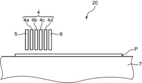
- FIG. 2 shows a side view of an example of the configuration of a portion of an inkjet textile printing device that can be used to produce a printed item according to an embodiment of the present disclosure.
- FIG. 2 mainly shows each component in a schematic manner. The size, number, etc. of each illustrated component may be changed as appropriate.
- the flatbed type inkjet printing device (part) 20 shown in Figure 2 ejects the pretreatment liquid, ink, and posttreatment liquid described above onto the printing object P.
- the inkjet printing device 20 shown in FIG. 2 includes an ink head 4, a pretreatment liquid head 5, a posttreatment liquid head 6, and a mounting table 7.
- the ink head 4 includes a first ink head 4a, a second ink head 4b, a third ink head 4c, and a fourth ink head 4d.
- the pretreatment liquid head 5 and the posttreatment liquid head 6 eject the pretreatment liquid and the posttreatment liquid, respectively, onto at least the image formation area of the printing object P.
- the pretreatment liquid head 5 and the posttreatment liquid head 6 are not particularly limited, but examples thereof include a piezoelectric head and a thermal inkjet head.
- the ink head 4 ejects ink onto the image forming area of the printing object P.
- the first ink head 4a, the second ink head 4b, the third ink head 4c, and the fourth ink head 4d of the ink head 4 each eject ink of a different color.
- the ink head 4 is not particularly limited, but examples thereof include a piezoelectric head and a thermal inkjet head.
- the printing object P is placed on the mounting table 7.
- a pretreatment liquid head 5, ink head 4, and posttreatment liquid head 6 are disposed above the mounting table 7 so that pretreatment liquid, ink, and posttreatment liquid can be ejected onto the printing object P.
- the mounting table 7 moves horizontally in a direction from the pretreatment liquid head 5 toward the posttreatment liquid head 6 (e.g., to the right in Figure 1). As the mounting table 7 moves horizontally, the printing object P on the mounting table 7 is transported.
- the placement table 7 on which the print target P is placed moves horizontally, and the print target P is transported to a position facing the pretreatment liquid head 5.
- Pretreatment liquid is ejected from the pretreatment liquid head 5 onto the print target P.
- the pretreatment liquid head 5 may eject pretreatment liquid only onto the image formation area of the print target P, may eject pretreatment liquid onto an area wider than the image formation area of the print target P, or may eject pretreatment liquid onto the entire surface of the print target P.
- it is preferable that the pretreatment liquid head 5 ejects pretreatment liquid only onto the image formation area of the print target P.
- the printing object P is transported to a position facing the ink head 4. Ink is discharged from the ink head 4 to the image forming area of the printing object P.
- the ink discharge amount discharge amount per time and total discharge amount
- the ink discharge amount (discharge amount per time and total discharge amount) for the printing object P needs to be appropriately adjusted while considering factors such as the type of the printing object P, the type of pigment in the ink, the physical properties of the ink such as the content, the discharge amount per time and the total discharge amount of the post-treatment liquid described later, the content of silicone oil in the post-treatment liquid, and the physical properties of the post-treatment liquid such as the viscosity of the post-treatment liquid.
- the amount of ink ejected is preferably 5 g/m2 or more and 40 g/m2 or less, more preferably 10 g/m2 or more and 40 g/m2 or less , and even more preferably 20 g/ m2 or more and 40 g/ m2 or less.
- total amount ejected is preferably 5 g/m2 or more and 40 g/m2 or less, more preferably 10 g/m2 or more and 40 g/m2 or less , and even more preferably 20 g/ m2 or more and 40 g/ m2 or less.
- the post-treatment liquid head 6 ejects the post-treatment liquid onto at least the image formation area of the printing object P.
- the post-treatment liquid head 6 may eject the post-treatment liquid onto only the image formation area of the printing object P.
- the post-treatment liquid head 6 may eject the post-treatment liquid onto an area wider than the image formation area of the printing object P.
- the ejection amount of the post-treatment liquid ejection amount per ejection and total ejection amount
- the ejection amount of the post-treatment liquid ejection amount per ejection and total ejection amount
- the amount of the post-treatment liquid discharged (amount discharged per time and total amount discharged) on the printing object P must be appropriately adjusted while considering factors such as the type of the printing object P, the amount of the ink discharged per time and the total amount discharged, the type of pigment in the ink, the physical properties of the ink such as the content, the content of silicone oil in the post-treatment liquid, and the physical properties of the post-treatment liquid such as the viscosity of the post-treatment liquid.
- the amount of the post-treatment liquid discharged is preferably 2 g/m 2 or more and less than 100 g/m 2 , more preferably 3 g/m 2 or more and 60 g/m 2 or less, even more preferably 4 g/m 2 or more and 45 g/m 2 or less, and particularly preferably 5 g/m 2 or more and 40 g/m 2 or less.
- the placement table 7 on which the printing object P is placed moves further horizontally, and the printing object P is transported to a position facing the heating unit (not shown).
- the heating unit heats the printing object P, thereby drying the pre-treatment liquid, ink, and post-treatment liquid.
- the heating temperature is, for example, 120°C or higher and 180°C or lower.
- the heating time is, for example, 1 minute or higher and 10 minutes or lower.
- the heating causes the volatile components contained in the pre-treatment liquid, ink, and post-treatment liquid to evaporate, promoting the fixation of the pre-treatment liquid, ink, and post-treatment liquid to the printing object P, and an image is formed using ink.
- a printed item is produced in which a treatment agent containing a pigment, binder resin particles, and a silicone component is attached to the printing object, and which has a penetration gradient such that the amount of silicone component decreases from the front side to the back side of the printed item.
- the printed material produced in this way has a penetration gradient of the silicone component as shown in Figure 1, and therefore has good texture and abrasion fastness properties.
- a spray or the like for applying the post-treatment liquid may be used to form a penetration gradient in the amount of silicone component.
- the mounting table 7 moves horizontally in the example of the manufacturing method described above, but the mounting table 7 may be fixed and the pretreatment liquid head 5, ink head 4, and posttreatment liquid head 6 may move horizontally to eject any of the pretreatment liquid, ink, and posttreatment liquid.
- the printed material according to this embodiment may be produced using an inkjet printing device that is not a flatbed type.
- FIG. 3 shows a perspective view of an example of the overall configuration of an inkjet printer that can be used to produce a printed item according to an embodiment of the present disclosure.
- the inkjet printer 1000 shown in FIG. 3 is suitable for use in digital textile printing, which uses an inkjet method to print images such as letters and patterns on a textile object made of fabric such as woven or knitted fabric. Alternatively, the inkjet printer 1000 may be used to print various images on a textile object such as a paper sheet or a resin sheet.
- FIG. 4 is a schematic cross-sectional view taken along line II-II in FIG. 3.
- the inkjet printer 1000 is a printer that prints images on a wide and long workpiece W (subject to be printed) using an inkjet method.
- the width of the workpiece W is several meters
- the inkjet printer 1000 includes an apparatus frame 100, and a work transport section 200 and a carriage 30 that are incorporated into the apparatus frame 100.
- the left-right direction is the main scanning direction S (see Figure 5) when printing on the workpiece W
- the direction from the rear to the front is the sub-scanning direction (the transport direction F of the workpiece W, which intersects with the main scanning direction S).
- the device frame 100 forms a framework for mounting various components of the inkjet printer 1000.
- the work transport unit 200 is a mechanism that intermittently feeds (transports) the work W so that the work W progresses in a transport direction F from rear to front in the printing area where the inkjet printing process is performed.
- the carriage 30 is equipped with the ink head 4, pre-treatment liquid head 5, post-treatment liquid head 6, and sub-tank 70, and moves back and forth in the main scanning direction S (left-right direction) that intersects with the transport direction F of the work W during the inkjet printing process.
- the device frame 100 includes a central frame 111, a right frame 112, and a left frame 113.
- the central frame 111 forms a framework for mounting various components of the inkjet printer 1000, and has a left-right width corresponding to the work transport section 200.
- the right frame 112 and the left frame 113 are erected to the right and left, respectively, of the central frame 111.
- Between the right frame 112 and the left frame 113 is the printing area 12 where printing processing is performed on the work W.
- the right frame 112 forms the maintenance area 13.
- the maintenance area 13 is an area where the carriage 30 is retracted when printing processing is not being performed.
- cleaning processing, purging processing, etc. of the nozzles (ejection holes) of the ink head 4, pre-treatment liquid head 5, and post-treatment liquid head 6 are performed.
- Caps are also fitted into the maintenance area 13.
- the left frame 113 forms the turn-around area 14 of the carriage 30.
- the turn-around area 14 is an area where the carriage 30 temporarily enters when it performs a main scan in the opposite direction after performing a main scan in the opposite direction from right to left in printing processing.
- a carriage guide 15 is attached to the upper side of the device frame 100 to allow the carriage 30 to move back and forth in the left-right direction.
- the carriage guide 15 is a flat member that is long in the left-right direction, and is disposed above the work transport section 200.
- a timing belt 16 is attached to the carriage guide 15 so that it can move in a circular motion in the left-right direction (main scanning direction).
- the timing belt 16 is an endless belt that is driven to move in a circular motion in the left or right direction.
- the carriage guide 15 is equipped with a pair of upper and lower guide rails 17 that extend parallel to the left and right and that hold the carriage 30 in a state in which it can move back and forth in the main scanning direction S.
- the carriage 30 engages with the guide rails 17.
- the carriage 30 is also fixed to the timing belt 16. As the timing belt 16 moves orbitally to the left or right, the carriage 30 moves left or right along the carriage guide 15 while being guided by the guide rails 17.
- the work transport section 200 includes a feed roller 21 that pays out the work W before printing, and a take-up roller 22 that takes up the work W after printing.
- the feed roller 21 is located at the rear lower part of the device frame 100, and is the take-up shaft of the feed roll WA, which is a roll of the work W before printing.
- the take-up roller 22 is located at the front lower part of the device frame 100, and is the take-up shaft of the take-up roll WB, which is a roll of the work W after the printing process.
- the take-up roller 22 is provided with a first motor M1 that drives the take-up roller 22 to rotate around its axis and perform the winding operation of the work W.
- the path between the delivery roller 21 and the take-up roller 22, passing through the printing area 12, is the transport path for the work W.
- a first tension roller 23 applies a predetermined tension to the work W on the upstream side of the transport roller 25.
- the work guide 24 changes the transport direction of the work W from upward to forward, allowing the work W to enter the printing area 12.
- the transport roller 25 is a roller that generates a transport force that intermittently feeds the workpiece W in the printing area 12.
- the transport roller 25 is driven to rotate about its axis by the second motor M2, and intermittently transports the workpiece W forward (predetermined transport direction F) so that the workpiece W passes through the printing area 12 (image forming position) facing the carriage 30.
- the pinch roller 26 is disposed to face the transport roller 25 from above, and forms a transport nip portion with the transport roller 25.
- the turn-back roller 27 changes the transport direction of the work W that has passed through the printing area 12 from the forward direction to the downward direction, and guides the work W after the printing process to the take-up roller 22.
- the second tension roller 28 applies a predetermined tension to the work W downstream of the transport roller 25.
- a platen 29 is disposed below the transport path of the work W in the printing area 12.
- the carriage 30 is supported by a cantilever on the guide rail 17 and moves back and forth in the main scanning direction S (left and right in Figs. 3 and 4) that intersects with the transport direction F (orthogonal in Figs. 3 and 4).
- the carriage 30 comprises a carriage frame 30A, and an ink head 4, a pre-treatment liquid head 5, a post-treatment liquid head 6, and a sub-tank 70 that are mounted on the carriage frame 30A (see Fig. 3).
- the carriage frame 30A includes a head support frame 31 and a back frame 32.
- the head support frame 31 is a horizontal plate that holds the ink head 4, pre-treatment liquid head 5, and post-treatment liquid head 6 described above.
- the back frame 32 is a vertical plate that extends upward from the rear edge of the head support frame 31. As described above, the timing belt 16 is fixed to the back frame 32. Also, the guide rail 17 is engaged with the back frame 32. That is, in the example shown in FIG. 4, the back frame 32 is an engagement portion that is held in a cantilevered state by the guide rail 17.
- the head support frame 31 is a horizontal plate whose rear end side is supported in a cantilevered state by the engagement portion on the guide rail 17.
- the cantilevered state refers to a state in which the engagement portion (back frame 32), which is the portion of the carriage 30 that is held by the guide rail 17, which is a holding member, is present only on one side, either upstream or downstream, from the center of the carriage 30 in the transport direction F, and no other engagement portion is present on the opposite side to the side where the engagement portion is present.
- the engagement portion may also be located outside the range in the transport direction F where the ink head 4 and the processing head are located. In other words, the engagement portion may be located only upstream or only downstream of the range in the transport direction F where the ink head 4, the pre-treatment liquid head 5, and the post-treatment liquid head 6 are located.
- Fig. 5 is an enlarged perspective view of the carriage shown in Fig. 3.
- Fig. 5 shows the transport direction F (sub-scanning direction) of the workpiece W and the main scanning direction S, which is the movement direction of the carriage 30.
- Fig. 5 shows an example in which the carriage 30 is equipped with a plurality of ink heads 4 that eject ink for image formation onto the workpiece W, a pre-treatment liquid head 5 and a post-treatment liquid head 6 that eject non-color-forming treatment liquid, and a plurality of sub-tanks 70 that supply ink, pre-treatment liquid, and post-treatment liquid to these ink heads 4, pre-treatment liquid head 5, and post-treatment liquid head 6.
- Each ink head 4 has a number of nozzles (ink ejection holes) that eject ink droplets using an ejection method such as a piezoelectric method using a piezoelectric element or a thermal method using a heating element, and ink passages that guide ink to the nozzles.
- an ejection method such as a piezoelectric method using a piezoelectric element or a thermal method using a heating element
- ink passages that guide ink to the nozzles.
- the ink for example, the inks described in detail above can be used.
- the multiple ink heads 4 are capable of ejecting eight colors of ink.
- the ink heads 4 are mounted on the head support frame 31 of the carriage 30 so as to be aligned in two rows in the main scanning direction S. Each color ink head 4 has two heads.
- the ink heads 4 have a first upstream ink head 41A and a first downstream ink head 41B. These ink heads 4 eject, for example, yellow ink.
- the ink heads 4 also have a second upstream ink head 42A and a second downstream ink head 42B. These ink heads 4 eject, for example, magenta ink.
- two ink heads 4 that eject ink of the same color are arranged at positions offset from each other in the transport direction F and the main scanning direction S. These two ink heads 4 form a set, and a total of eight sets of ink heads 4 (41A-48A, 41B-48B) eject ink of different colors.
- the pre-treatment liquid head 5 and the post-treatment liquid head 6 are disposed at different positions from the ink head 4 in the transport direction F.
- the pre-treatment liquid head 5 is disposed upstream of the ink head 4 in the transport direction F.
- FIG. 5 shows an example in which one pre-treatment liquid head 5 is disposed near the left end of the array of ink heads 4.
- the post-treatment liquid head 6 is disposed downstream of the ink head 4 in the transport direction F.
- FIG. 5 shows an example in which one post-treatment liquid head 6 is disposed at the right end of the array of ink heads 4.
- multiple pre-treatment liquid heads 5 or multiple post-treatment liquid heads 6 may be disposed.
- the series of heads along the main scanning direction S, which is made up of the ink heads 4, pretreatment liquid heads 5, and posttreatment liquid heads 6, is referred to as a row of heads, or simply as a row.
- the series of heads along the transport direction F, which is made up of the ink heads 4, pretreatment liquid heads 5, and posttreatment liquid heads 6, is referred to as a row of heads, or simply as a row.
- the pretreatment liquid head 5 ejects pretreatment liquid for performing a predetermined pretreatment on the workpiece W.
- the pretreatment liquid is ejected from the pretreatment liquid head 5 to a position on the workpiece W where ink has not yet been ejected from the ink head 4.
- the pretreatment liquid may be the same as that described above.
- the post-treatment liquid head 6 ejects post-treatment liquid for performing a predetermined post-treatment on the workpiece W to which ink has been attached.
- the post-treatment liquid is ejected from the post-treatment liquid head 6 to the position of the workpiece W after the ink has been ejected from the ink head 4.
- the post-treatment liquid may be the same as that described above.
- the amount of post-treatment liquid ejected is adjusted to an appropriate amount so that a penetration gradient is formed in which the amount of silicone component decreases from the front side to the back side of the printed material, as described above.
- pretreatment liquid, ink, and posttreatment liquid are ejected in that order onto the workpiece W in the areas where colors will be printed according to the image.
- the ink may be of one color or multiple colors.
- pretreatment liquid and posttreatment liquid are generally not ejected either.
- openings 31H are provided at the locations of the heads on the head support frame 31.
- the ink head 4, pre-treatment liquid head 5, and post-treatment liquid head 6 are attached to the head support frame 31 so as to fit into the respective openings 31H.
- Nozzles arranged on the lower end surface of each head are exposed from each opening 31H.
- the multiple sub-tanks 70 are supported by the carriage 30 above each head (ink head 4, pre-treatment liquid head 5, and post-treatment liquid head 6) via a holding frame (not shown).
- the multiple sub-tanks 70 are provided corresponding to each of the ink head 4, pre-treatment liquid head 5, and post-treatment liquid head 6.
- Ink or treatment liquid is supplied to each sub-tank 70 from a main tank 90 that contains ink and treatment liquid, and these are supplied to each head.
- Each sub-tank 70 and each head are connected by a pipe (not shown).
- the multiple subtanks 70 include a first supply subtank 71A to an eighth supply subtank 78A, a pre-processing supply subtank 7FA, and a post-processing supply subtank 7RA arranged on the rear side along the main scanning direction S. Furthermore, the multiple subtanks 70 include a first recovery subtank 71B to an eighth recovery subtank 78B, a pre-processing recovery subtank 7FB, and a post-processing recovery subtank 7RB arranged on the front side along the main scanning direction S.
- the first supply subtank 71A and the first recovery subtank 71B located on the far left side of the carriage 30 store, for example, yellow ink containing a pigment.
- the first supply subtank 71A supplies yellow ink to the first upstream ink head 41A and the first downstream ink head 41B (both of which are also referred to as supply destinations).
- the first recovery subtank 71B stores the yellow ink recovered from the first upstream ink head 41A and the first downstream ink head 41B. As described above, a portion of the yellow ink is ejected toward the workpiece W from the first upstream ink head 41A and the first downstream ink head 41B.
- the second supply subtank 72A supplies magenta ink to the second upstream ink head 42A and the second downstream ink head 42B.
- the second recovery subtank 72B stores the magenta ink recovered from the second upstream ink head 42A and the second downstream ink head 42B.
- the other sub-tanks, numbered 3 to 8, have the same structure and function as described above.
- the pre-treatment supply sub-tank 7FA supplies pre-treatment liquid to the pre-treatment liquid head 5, and the pre-treatment recovery sub-tank 7FB recovers pre-treatment liquid from the pre-treatment liquid head 5.
- the post-treatment supply sub-tank 7RA supplies post-treatment liquid to the post-treatment liquid head 6, and the post-treatment recovery sub-tank 7RB recovers post-treatment liquid from the post-treatment liquid head 6.
- the inkjet printer 1000 shown in Figures 3 to 5 is an all-in-one printer in which three types of heads, the ink head 4, the pretreatment liquid head 5, and the posttreatment liquid head 6, are mounted on a single carriage 30.
- the pretreatment liquid ejection process and the posttreatment liquid ejection process can be executed integrally. This makes it possible to simplify the textile printing process, make the textile printing device more compact, etc.
- the inkjet printer 1000 shown in Figures 3 to 5 performs printing on the workpiece W using a serial printing method. Specifically, if the workpiece W is wide, it is generally not possible to print while continuously feeding the workpiece W.
- the serial printing method is a printing method in which the carriage 30 carrying the ink heads 4 of each color moves back and forth in the main scanning direction S, and the workpiece W is intermittently fed in the transport direction F.
- a strip image is printed while the carriage 30 moves in the forward direction, which is one of the main scanning directions S.
- the feed of the workpiece W is stopped.
- the workpiece W is sent out in the transport direction F by a specified pitch.
- the carriage 30 waits in the turn-back area 14 on the left end side.
- the carriage 30 turns back in the return direction, which is opposite to the forward direction, as the timing belt 16 moves in reverse.
- the workpiece W is stationary.
- the carriage 30 prints the next strip image upstream of the strip image printed during the forward movement. The same operation is repeated thereafter.
- a printed matter according to a first aspect of the present disclosure is a printed matter in which a treatment agent containing a pigment, binder resin particles, and a silicone component is adhered to a printing subject,
- the silicone component is present on both the front surface and the back surface of the print, and
- the amount of the silicone component is less on the back surface than on the front surface.
- This print has good texture and abrasion resistance.
- the printed material according to the second aspect of the present disclosure is the printed material according to the first aspect, in which the ratio of the amount of the silicone component on the back surface to the amount of the silicone component on the front surface is 70% or less.
- the printed material according to the third aspect of the present disclosure is the printed material according to the second aspect, in which the ratio of the amount of the silicone component on the back surface to the amount of the silicone component on the front surface is greater than 15%.
- the printed item can be sure to have a good texture.
- the printed material according to the fourth aspect of the present disclosure is the printed material according to the third aspect, in which the ratio of the amount of the silicone component on the back surface to the amount of the silicone component on the front surface is 31% or more.
- the printed item can be more reliably provided with a good texture.
- the printed material according to the fifth aspect of the present disclosure is the printed material according to the fourth aspect, in which the ratio of the amount of the silicone component on the back surface to the amount of the silicone component on the front surface is 46% or more and 60% or less.
- the printed item can be more reliably provided with good texture and abrasion fastness properties (especially wet abrasion fastness).
- the printed material according to the sixth aspect of the present disclosure is a printed material according to any one of the first to fifth aspects, in which the pigment is present on the front surface of the printed material and in an inner layer portion between the front surface and the back surface of the printed material.
- This configuration allows the color of the printed image to be more vivid.
- the printed material according to the seventh aspect of the present disclosure is a printed material according to any one of the first to sixth aspects, in which the pigment is not present on the rear surface of the printed material.
- the printed item according to the eighth aspect of the present disclosure is a printed item according to any one of the first to seventh aspects, and the subject of printing is a polyester fabric.
- the printed material according to the ninth aspect of the present disclosure is a printed material according to any one of the first to eighth aspects, and is an inkjet printed material.
- various prints for evaluation were prepared by varying the ratio of the amount of detected Si on the back surface to the front surface of the print. Furthermore, the texture and friction fastness of each print for evaluation were evaluated. In addition, the cross-sections of the prints for evaluation prepared were observed to confirm the location of the pigment, and the color development of the prints for evaluation prepared was also evaluated.
- Example 1 The evaluation printed material of Example 1 was produced by ejecting the pre-treatment liquid, ink (Black) and post-treatment liquid in that order onto the polyester tropical material to be printed using an inkjet printer.
- the methods for producing the pre-treatment liquid, ink and post-treatment liquid, as well as the method for producing the evaluation printed material of Example 1 using these will be described below.
- a regulated cationic polymer solution to be contained in the pretreatment solution was prepared.
- a column was filled with 0.5 L of a strongly basic ion exchange resin (OH type), and 1 L of "PAS-A-5" (manufactured by Nittobo Medical Co., Ltd.) was passed through the column at a flow rate of 50 mL/min to obtain a regulated cationic polymer solution.
- "PAS-A-5" is a cationic polymer of a quaternary ammonium salt (diallyldimethylammonium chloride-sulfur dioxide copolymer).
- the solid content of the obtained regulated cationic polymer solution was 40%.
- a silicone emulsion to be contained in the post-treatment liquid was prepared. Specifically, 300 g of amino-modified silicone oil ("KF-864" manufactured by Shin-Etsu Chemical Co., Ltd., viscosity: 1,700 mm 2 /s, specific gravity: 0.98 (25°C), functional group equivalent: 3,800 g/mol), 600 g of ion-exchanged water, and 100 g of hydrochloric acid aqueous solution (concentration: 1 mol/L) were placed in a beaker.
- KF-864" manufactured by Shin-Etsu Chemical Co., Ltd., viscosity: 1,700 mm 2 /s, specific gravity: 0.98 (25°C), functional group equivalent: 3,800 g/mol
- 600 g of ion-exchanged water 600 g
- hydrochloric acid aqueous solution concentration: 1 mol/L
- the contents of the beaker were stirred at a rotation speed of 10,000 rpm for 15 minutes using a homogenizer ("Ultra Turrax T25" manufactured by IKA Corporation), and allowed to stand for 30 minutes.
- a homogenizer (“Ultra Turrax T25" manufactured by IKA Corporation)
- the contents of the beaker were filtered through a 120-mesh stainless steel filter to obtain a silicone emulsion.
- a post-treatment liquid was prepared using the silicone emulsion prepared as described above. Specifically, the post-treatment liquid was obtained by mixing 30 g of the silicone emulsion, 35 g of ion-exchanged water, and 35 g of propylene glycol.
- the third print head was filled with the post-treatment liquid prepared above.
- the pretreatment liquid, the ink (Black), and the posttreatment liquid were discharged from each head onto polyester tropical so that the discharge amounts (total discharge amounts) were 10 g/m 2 , 20 g/m 2 , and 5 g/m 2 , respectively.
- the droplet sizes discharged by the head were 18 pl/time for the ink and 9 pl/time for each treatment liquid.
- the ink was discharged the required number of times according to each total discharge amount.
- the ink and each treatment liquid were printed with an interval of 1 sec between them.
- the inkjet printing conditions were a cloth/head distance of 3 mm and a head temperature of 25° C.
- the printing target was heated in an oven at 160° C. for 3 minutes to dry the ink and both treatment liquids, and the evaluation printed material of Example 1 was obtained.
- Example 2 A printed textile for evaluation of Example 2 was produced in the same manner as in Example 1, except that the amount of post-treatment liquid discharged (total amount discharged) when producing a printed textile for evaluation was 20 g/m 2 .
- Example 3 A printed textile for evaluation of Example 3 was produced in the same manner as in Example 1, except that the amount of post-treatment liquid discharged (total amount discharged) when producing a printed textile for evaluation was 40 g/m 2 .
- Example 4 The printed fabric for evaluation in Example 4 was produced in the same manner as in Example 1, except that a cotton broadcloth (manufactured by Irosen Co., Ltd., size: A4 size, cotton count of warp and weft: 40/1, warp density: 130 threads/inch, weft density: 75 threads/inch, basis weight: 122 g/ m2 ) was used as the printing subject.
- a cotton broadcloth manufactured by Irosen Co., Ltd., size: A4 size, cotton count of warp and weft: 40/1, warp density: 130 threads/inch, weft density: 75 threads/inch, basis weight: 122 g/ m2 ) was used as the printing subject.
- Example 5 A printed material for evaluation of Example 5 was prepared in the same manner as in Example 1, except that an ink (Yellow) prepared by the following method was used instead of the ink (Black).
- Pigment Yellow 74 solid content concentration: 20% by mass
- a binder resin particle dispersion (“Superflex 420" manufactured by Daiichi Kogyo Seiyaku Co., Ltd., content: polyurethane dispersion, solid content concentration: 32% by mass) were added in this order to the flask. The contents of the flask were further stirred for 10 minutes to obtain an ink (Yellow).
- Example 6 The printed textile for evaluation of Example 6 was prepared in the same manner as in Example 1, except that when preparing the printed textile for evaluation, the post-treatment liquid was applied to the printed subject in an amount of 10 g/ m2 (total amount applied) using a spray.
- Example 7 A printed material for evaluation of Example 7 was prepared in the same manner as in Example 1, except that an ink (cyan) prepared in the following manner was used instead of the ink (black).
- Example 8 A printed material for evaluation of Example 8 was prepared in the same manner as in Example 1, except that an ink (magenta) prepared by the following method was used instead of the ink (black).
- Pigment Red 122, solid content concentration: 20% by mass), and 125 g of a binder resin particle dispersion ("Superflex 420" manufactured by Daiichi Kogyo Seiyaku Co., Ltd., content: polyurethane dispersion, solid content concentration: 32% by mass) were added in this order to the flask.
- the contents of the flask were further stirred for 10 minutes to obtain an ink (Magenta).
- Example 9 The printed textile for evaluation of Example 9 was produced in the same manner as in Example 1, except that the ejection amount (total ejection amount) of the ink (Black) when producing the printed textile for evaluation was 10 g/m 2 .
- Example 10 The printed textile for evaluation of Example 10 was produced in the same manner as in Example 1, except that the amount of the post-treatment liquid discharged (total amount discharged) when producing the printed textile for evaluation was 10 g/m 2 .
- Example 11 A polyester satin fabric (Stretch Royal Satin manufactured by Uni Seni Co., Ltd., warp density: approximately 100 threads/inch (actual measurement), weft density: approximately 80 threads/inch (actual measurement), basis weight: approximately 100 g/ m2 (actual measurement)) was used as the printing subject, and the evaluation printed fabric of Example 11 was produced in the same manner as in Example 1, except that the ejection amounts (total ejection amounts) of the ink (Black) and post-treatment liquid when producing the evaluation printed fabric were 40 g/ m2 and 10 g/ m2, respectively.
- Example 12 The printed fabric for evaluation of Example 12 was produced in the same manner as in Example 1, except that a nylon taffeta fabric (R5050 manufactured by Uni Seni Co., Ltd., warp density: approximately 100 threads/inch (actual measurement), weft density: approximately 80 threads/inch (actual measurement), basis weight: approximately 70 g/m2 (actual measurement)) was used as the printing target.
- a nylon taffeta fabric R5050 manufactured by Uni Seni Co., Ltd., warp density: approximately 100 threads/inch (actual measurement), weft density: approximately 80 threads/inch (actual measurement), basis weight: approximately 70 g/m2 (actual measurement)
- Example 13 The evaluation printed material of Example 13 was produced in the same manner as in Example 1, except that acetate satin fabric (KKF2660 acetate melon vintage satin manufactured by Uni Seni Co., Ltd., warp density: approximately 100 threads/inch (actual measurement), weft density: approximately 80 threads/inch (actual measurement), basis weight: approximately 120 g/ m2 (actual measurement)) was used as the printing target.
- acetate satin fabric KF2660 acetate melon vintage satin manufactured by Uni Seni Co., Ltd., warp density: approximately 100 threads/inch (actual measurement), weft density: approximately 80 threads/inch (actual measurement), basis weight: approximately 120 g/ m2 (actual measurement)
- Example 14 A printed material for evaluation of Example 14 was produced in the same manner as in Example 13, except that the ejection amounts (total ejection amounts) of the ink (Black) and the post-treatment liquid when producing the printed material for evaluation were 40 g/ m2 and 10 g/ m2 , respectively.
- Example 15 A printed fabric for evaluation of Example 15 was prepared in the same manner as in Example 1, except that a rayon spun muslin fabric (manufactured by Shikisensha Co., Ltd., warp thread: 40-count 1 thread, weft thread: 40-count 1 thread, warp density: 87 threads/inch, weft density: 72 threads/inch, basis weight: 99 g/ m2 ) was used as the printing target.
- a rayon spun muslin fabric manufactured by Shikisensha Co., Ltd., warp thread: 40-count 1 thread, weft thread: 40-count 1 thread, warp density: 87 threads/inch, weft density: 72 threads/inch, basis weight: 99 g/ m2
- Example 16 A printed material for evaluation of Example 16 was produced in the same manner as in Example 15, except that the ejection amounts (total ejection amounts) of the ink (Black) and the post-treatment liquid when producing the printed material for evaluation were 40 g/ m2 and 10 g/ m2 , respectively.
- Example 17 A printed fabric for evaluation of Example 17 was produced in the same manner as in Example 1, except that Tencel satin fabric (TN8811 manufactured by Uni Seni Co., Ltd., warp thread: 80 count-1 thread, weft thread: 80 count-1 thread, warp thread density: 210 threads/inch, weft thread density: 120 threads/inch, basis weight: approximately 100 g/ m2 (actual measurement)) was used as the printing target.
- Tencel satin fabric TN8811 manufactured by Uni Seni Co., Ltd., warp thread: 80 count-1 thread, weft thread: 80 count-1 thread, warp thread density: 210 threads/inch, weft thread density: 120 threads/inch, basis weight: approximately 100 g/ m2 (actual measurement)
- Example 18 The printed material for evaluation of Example 18 was prepared in the same manner as in Example 17, except that the ejection amounts (total ejection amounts) of the ink (Black) and the post-treatment liquid when preparing the printed material for evaluation were 40 g/ m2 and 10 g/ m2 , respectively.
- Example 19 The printed textile for evaluation of Example 19 was produced in the same manner as in Example 4, except that the ejection amount (total ejection amount) of the ink (Black) when producing the printed textile for evaluation was 10 g/ m2 .
- Example 20 The printed textile for evaluation of Example 20 was produced in the same manner as in Example 4, except that the amount of the post-treatment liquid discharged (total amount discharged) when producing the printed textile for evaluation was 10 g/m 2 .
- Example 21 The printed material for evaluation of Example 21 was produced in the same manner as in Example 4, except that the ejection amounts (total ejection amounts) of the ink (Black) and the post-treatment liquid when producing the printed material for evaluation were 40 g/ m2 and 10 g/ m2 , respectively.
- Comparative Example 1 A printed textile for evaluation of Comparative Example 1 was prepared in the same manner as in Example 1, except that the post-treatment liquid was not ejected, applied, or the like during preparation of the printed textile for evaluation.
- Comparative Example 2 The printed material of Comparative Example 2 was produced in the same manner as in Example 1, except that the post-treatment liquid was applied to the printing object by immersion in an amount of 100 g/ m2 (total amount applied).
- the mass % of Si was defined as the amount of Si detected when the total of C, O, Si, and Au was 100 Mass %.
- the amount of Si detected was measured by measuring both the amount of Si detected on the front surface of the evaluation printed materials and the amount of Si detected on the back surface.
- Table 1 below shows the amount of Si detected on the front surface, the amount of Si detected on the back surface, and the ratio of the amount of Si detected on the back surface to the amount of Si detected on the front surface for the evaluation printed materials of each Example and Comparative Example, along with the printing target, the amount of ink discharged (total amount discharged) and its type, and the amount of post-treatment liquid discharged (total amount discharged) or applied (total amount applied) and processing method.
- the Si detection ratio was calculated by rounding off to one decimal place.
- PET1 means polyester tropical fabric.
- Cotton means cotton broadcloth fabric.
- PET2 means polyester satin fabric.
- Ny means nylon taffeta fabric.
- Acetate means acetate satin fabric.
- Rayon means rayon spun muslin fabric.
- Lyocell means Tencel satin fabric.
- IJ means inkjet printing method
- SP means spray method
- DP means immersion method.
- Evaluation A The rate of change in loop height is less than 130%.
- Evaluation A' The rate of change in loop height is 130%.
- Evaluation B The rate of change in loop height is more than 130%.
- the degree of coloring of the white cotton cloth for friction was judged on a 9-level scale (1st grade, 1-2nd grade, 2nd grade, 2-3rd grade, 3rd grade, 3-4th grade, 4th grade, 4-5th grade, and 5th grade in order of increasing degree of contamination).
- the dry friction fastness and wet friction fastness were evaluated according to the following criteria based on the degree of coloring of the white cotton friction cloth after the friction test. The result of the dry test was taken as the dry friction fastness, and the result of the wet test was taken as the wet friction fastness.
- Evaluation A Dry friction fastness is grade 3 or higher.
- Evaluation B The dry friction fastness is less than grade 3.
- Evaluation A Wet friction fastness is grade 2 or higher.
- Evaluation A' Wet rubbing fastness is grade 1-2.
- Evaluation B Wet rubbing fastness is less than grade 1 or 2.
- the Si detection amount ratio of the back surface of the printed material to the front surface can vary not only depending on factors such as the discharge amount (total discharge amount), the application amount (total application amount) of the post-treatment liquid, but also depending on factors such as the type of the printed material, the discharge amount (total discharge amount) of the ink, and the type of the ink.
- the evaluation printed material was prepared by the same method as in Example 1 except that the printed material used was different, but the Si detection ratio of the back surface of the evaluation printed material to the front surface was significantly different.
- the Si detection ratio in each printed material also varies depending on the droplet size of the ink and the post-treatment liquid (or the pre-treatment liquid, the ink, and the post-treatment liquid), the number of discharges, the discharge interval of these liquids, and the specific discharge, application, or application method of these liquids. This is thought to be because, for example, the droplet size, the number of discharges, the discharge interval, etc. affect the penetration into the fabric differently depending on the type of the printed material.
- the texture of the printed material was better.
- the Si detection ratio of the back surface to the front surface of the evaluation printed material was preferably between 31% and 60%, and more preferably between 46% and 60%, both the texture and the friction fastness properties (particularly wet friction fastness) of the printed material tended to be generally better.
- the tactile feel of cotton broadcloth and the like is easily deteriorated by printing, and the rate of change in loop height tended to be slightly greater than when other types of printed materials were used.
- the print for evaluation in Comparative Example 1 was not treated with a post-treatment liquid, and therefore the texture of the print was significantly inferior.
- the print for evaluation in Comparative Example 2 had poor dry rub fastness. This is thought to be because the amount of silicone component on the back surface was greater than the amount of silicone component on the front surface, and therefore the rub resistance of the image formed on the front side of the print was reduced.
- the image density (OD) of the evaluation printed material of Example 1 was 1.28, and the evaluation result of color development was good. From this result, it was found that the image color development becomes vivid when the pigment is present only on the front surface of the printed material and in the inner layer part of the printed material. Furthermore, the image density (OD) of the evaluation printed material of Example 4, which is a cotton broadcloth fabric to be printed, was 1.30, and the evaluation result of color development was good. Furthermore, the image density (OD) of the evaluation printed material of Example 5, which is a yellow ink, was 1.25, and the evaluation result of color development was good.
Landscapes
- Engineering & Computer Science (AREA)
- Textile Engineering (AREA)
- Ink Jet (AREA)
- Treatment Of Fiber Materials (AREA)
- Coloring (AREA)
- Treatments For Attaching Organic Compounds To Fibrous Goods (AREA)
- Ink Jet Recording Methods And Recording Media Thereof (AREA)
Priority Applications (4)
| Application Number | Priority Date | Filing Date | Title |
|---|---|---|---|
| CN202480034011.3A CN121175460A (zh) | 2023-06-06 | 2024-06-05 | 印花物 |
| JP2025504371A JP7749159B2 (ja) | 2023-06-06 | 2024-06-05 | 捺染物 |
| EP24819365.8A EP4707461A1 (en) | 2023-06-06 | 2024-06-05 | Printed material |
| JP2025157045A JP2025183392A (ja) | 2023-06-06 | 2025-09-22 | 捺染物 |
Applications Claiming Priority (4)
| Application Number | Priority Date | Filing Date | Title |
|---|---|---|---|
| JP2023093424 | 2023-06-06 | ||
| JP2023-093424 | 2023-06-06 | ||
| JPPCT/JP2023/046879 | 2023-12-27 | ||
| PCT/JP2023/046879 WO2024252701A1 (ja) | 2023-06-06 | 2023-12-27 | 捺染物 |
Publications (1)
| Publication Number | Publication Date |
|---|---|
| WO2024253137A1 true WO2024253137A1 (ja) | 2024-12-12 |
Family
ID=93795519
Family Applications (1)
| Application Number | Title | Priority Date | Filing Date |
|---|---|---|---|
| PCT/JP2024/020562 Ceased WO2024253137A1 (ja) | 2023-06-06 | 2024-06-05 | 捺染物 |
Country Status (4)
| Country | Link |
|---|---|
| EP (1) | EP4707461A1 (https=) |
| JP (2) | JP7749159B2 (https=) |
| CN (1) | CN121175460A (https=) |
| WO (1) | WO2024253137A1 (https=) |
Citations (5)
| Publication number | Priority date | Publication date | Assignee | Title |
|---|---|---|---|---|
| JP2019147307A (ja) | 2018-02-27 | 2019-09-05 | セイコーエプソン株式会社 | インクジェット記録方法及び記録装置 |
| WO2021182338A1 (ja) * | 2020-03-10 | 2021-09-16 | 京セラドキュメントソリューションズ株式会社 | インクジェット用処理液、インクジェット捺染装置、及びインクジェット捺染方法 |
| WO2021210462A1 (ja) * | 2020-04-13 | 2021-10-21 | 京セラドキュメントソリューションズ株式会社 | インクジェット捺染用処理液、インクジェット捺染装置、インクジェット捺染方法及び捺染物 |
| WO2023037922A1 (ja) * | 2021-09-07 | 2023-03-16 | 京セラ株式会社 | インクジェット用処理液、インクジェット捺染装置、およびインクジェット捺染方法 |
| JP2023093424A (ja) | 2018-04-11 | 2023-07-04 | フラウンホーファー-ゲゼルシャフト ツール フエルデルング デア アンゲヴァンテン フォルシュング エー.ファオ. | 管状構造体内の物体の位置を決定するための位置決定装置 |
-
2024
- 2024-06-05 EP EP24819365.8A patent/EP4707461A1/en active Pending
- 2024-06-05 CN CN202480034011.3A patent/CN121175460A/zh active Pending
- 2024-06-05 JP JP2025504371A patent/JP7749159B2/ja active Active
- 2024-06-05 WO PCT/JP2024/020562 patent/WO2024253137A1/ja not_active Ceased
-
2025
- 2025-09-22 JP JP2025157045A patent/JP2025183392A/ja active Pending
Patent Citations (5)
| Publication number | Priority date | Publication date | Assignee | Title |
|---|---|---|---|---|
| JP2019147307A (ja) | 2018-02-27 | 2019-09-05 | セイコーエプソン株式会社 | インクジェット記録方法及び記録装置 |
| JP2023093424A (ja) | 2018-04-11 | 2023-07-04 | フラウンホーファー-ゲゼルシャフト ツール フエルデルング デア アンゲヴァンテン フォルシュング エー.ファオ. | 管状構造体内の物体の位置を決定するための位置決定装置 |
| WO2021182338A1 (ja) * | 2020-03-10 | 2021-09-16 | 京セラドキュメントソリューションズ株式会社 | インクジェット用処理液、インクジェット捺染装置、及びインクジェット捺染方法 |
| WO2021210462A1 (ja) * | 2020-04-13 | 2021-10-21 | 京セラドキュメントソリューションズ株式会社 | インクジェット捺染用処理液、インクジェット捺染装置、インクジェット捺染方法及び捺染物 |
| WO2023037922A1 (ja) * | 2021-09-07 | 2023-03-16 | 京セラ株式会社 | インクジェット用処理液、インクジェット捺染装置、およびインクジェット捺染方法 |
Also Published As
| Publication number | Publication date |
|---|---|
| JP2025183392A (ja) | 2025-12-16 |
| EP4707461A1 (en) | 2026-03-11 |
| JP7749159B2 (ja) | 2025-10-03 |
| CN121175460A (zh) | 2025-12-19 |
| JPWO2024253137A1 (https=) | 2024-12-12 |
Similar Documents
| Publication | Publication Date | Title |
|---|---|---|
| JP7401007B2 (ja) | 捺染物、捺染物の製造方法及びインクジェット捺染装置 | |
| JP2014091772A (ja) | インクジェット記録用のインク、インクジェット記録システム | |
| JP2012179825A (ja) | インクジェット記録方法 | |
| US20250051600A1 (en) | Ink-jet treatment liquid, ink-jet textile printing device, and ink-jet textile printing method | |
| JP7342305B2 (ja) | インクジェット用処理液、インクジェット捺染装置、およびインクジェット捺染方法 | |
| US20250052001A1 (en) | Ink-jet treatment liquid, ink-jet textile printing device, and ink-jet textile printing method | |
| JP2020082568A (ja) | 払拭装置、液体吐出装置、及び払拭方法 | |
| JP2025081351A (ja) | インクジェット用処理液、並びに、それを用いたインクセット及び捺染方法 | |
| US20070003715A1 (en) | Ink-jet recording ink, ink-jet recording method, recording medium, and ink-jet recording device | |
| JP7749159B2 (ja) | 捺染物 | |
| WO2024252701A1 (ja) | 捺染物 | |
| CN118043207B (zh) | 喷墨用处理液、喷墨印花装置及喷墨印花方法 | |
| EP4703514A1 (en) | Ink set for inkjet textile printing, inkjet textile printing method, and inkjet textile printing device | |
| JP2004074432A (ja) | 水性プレコート液及びインクジェット記録方法 | |
| WO2025142754A1 (ja) | インクジェット捺染用処理液、インクジェット捺染用インクセット、インクジェット捺染方法、及びインクジェット捺染装置 | |
| JP7694648B2 (ja) | インクジェット記録用インクセット、インクジェット記録方法、メンテナンス方法及びインクジェット記録装置 | |
| JP3501519B2 (ja) | インクジェット捺染用布帛、インクジェット捺染方法およびインクジェット捺染物 |
Legal Events
| Date | Code | Title | Description |
|---|---|---|---|
| 121 | Ep: the epo has been informed by wipo that ep was designated in this application |
Ref document number: 24819365 Country of ref document: EP Kind code of ref document: A1 |
|
| WWE | Wipo information: entry into national phase |
Ref document number: 2025504371 Country of ref document: JP |
|
| WWE | Wipo information: entry into national phase |
Ref document number: 2024819365 Country of ref document: EP |
|
| ENP | Entry into the national phase |
Ref document number: 2024819365 Country of ref document: EP Effective date: 20251124 |
|
| ENP | Entry into the national phase |
Ref document number: 2024819365 Country of ref document: EP Effective date: 20251124 |
|
| ENP | Entry into the national phase |
Ref document number: 2024819365 Country of ref document: EP Effective date: 20251124 |
|
| ENP | Entry into the national phase |
Ref document number: 2024819365 Country of ref document: EP Effective date: 20251124 |
|
| ENP | Entry into the national phase |
Ref document number: 2024819365 Country of ref document: EP Effective date: 20251124 |
|
| ENP | Entry into the national phase |
Ref document number: 2024819365 Country of ref document: EP Effective date: 20251124 |
|
| NENP | Non-entry into the national phase |
Ref country code: DE |
|
| ENP | Entry into the national phase |
Ref document number: 2024819365 Country of ref document: EP Effective date: 20251124 |
|
| ENP | Entry into the national phase |
Ref document number: 2024819365 Country of ref document: EP Effective date: 20251124 |
|
| ENP | Entry into the national phase |
Ref document number: 2024819365 Country of ref document: EP Effective date: 20251124 |
|
| ENP | Entry into the national phase |
Ref document number: 2024819365 Country of ref document: EP Effective date: 20251124 |
|
| WWP | Wipo information: published in national office |
Ref document number: 2024819365 Country of ref document: EP |