WO2024253015A1 - 塗装ロボットシステムおよびロボット - Google Patents
塗装ロボットシステムおよびロボット Download PDFInfo
- Publication number
- WO2024253015A1 WO2024253015A1 PCT/JP2024/019856 JP2024019856W WO2024253015A1 WO 2024253015 A1 WO2024253015 A1 WO 2024253015A1 JP 2024019856 W JP2024019856 W JP 2024019856W WO 2024253015 A1 WO2024253015 A1 WO 2024253015A1
- Authority
- WO
- WIPO (PCT)
- Prior art keywords
- arm
- tip
- base end
- base
- painting
- Prior art date
- Legal status (The legal status is an assumption and is not a legal conclusion. Google has not performed a legal analysis and makes no representation as to the accuracy of the status listed.)
- Ceased
Links
Images





Classifications
-
- B—PERFORMING OPERATIONS; TRANSPORTING
- B05—SPRAYING OR ATOMISING IN GENERAL; APPLYING FLUENT MATERIALS TO SURFACES, IN GENERAL
- B05B—SPRAYING APPARATUS; ATOMISING APPARATUS; NOZZLES
- B05B12/00—Arrangements for controlling delivery; Arrangements for controlling the spray area
-
- B—PERFORMING OPERATIONS; TRANSPORTING
- B25—HAND TOOLS; PORTABLE POWER-DRIVEN TOOLS; MANIPULATORS
- B25J—MANIPULATORS; CHAMBERS PROVIDED WITH MANIPULATION DEVICES
- B25J9/00—Program-controlled manipulators
- B25J9/06—Program-controlled manipulators characterised by multi-articulated arms
Definitions
- This disclosure relates to a painting robot system and a robot.
- JP 2018-183843 A discloses a seven-axis vertical articulated robot.
- the seven-axis vertical articulated robot of JP 2018-183843 A includes a base, a lower arm, an upper arm, and a wrist.
- a first arm and a second arm that bend relative to each other are disposed between the upper arm and the wrist.
- the seven-axis vertical articulated robot of JP 2018-183843 A has an additional seventh axis joint for bending the first arm and second arm, in comparison to a conventional six-axis vertical articulated robot.
- the seven-axis vertical articulated robot disclosed in JP 2018-183843 A is more compact in size than conventional six-axis vertical articulated robots by bending the seventh axis joint. Therefore, when arranging multiple seven-axis vertical articulated robots, the seven-axis vertical articulated robots can be arranged closely together while avoiding interference between the seven-axis vertical articulated robots. As a result, it is possible to reduce the arrangement area in which the seven-axis vertical articulated robots are arranged.
- This disclosure has been made to solve the problems described above, and one objective of this disclosure is to provide a painting robot system and a robot that can be placed in a smaller placement area.
- the painting robot system includes a plurality of vertically articulated robots that perform painting work on a workpiece, and at least one of the plurality of robots includes a base arm section, a tip arm section whose base end is connected to the base arm section, a wrist section whose base end is connected to the tip arm section and to which a painting tool is attached at its tip, and a telescopic shaft that is disposed on at least one of the base arm section and the tip arm section and that extends and retracts at least one of the base arm section and the tip arm section.
- the painting robot system includes a telescopic shaft that is disposed on at least one of the base arm portion and the tip arm portion, as described above, and that telescopically extends or retracts at least one of the base arm portion and the tip arm portion.
- a telescopic shaft that is disposed on at least one of the base arm portion and the tip arm portion, as described above, and that telescopically extends or retracts at least one of the base arm portion and the tip arm portion.
- at least one of the base arm portion and the tip arm portion contracts, thereby reducing the overall length of at least one of the base arm portion and the tip arm portion.
- the robots can be arranged closer together, allowing the robots to be arranged in a smaller arrangement area.
- painting work can be performed on a distant workpiece by extending at least one of the base arm portion and the tip arm portion using the telescopic
- the robot according to the second aspect of this disclosure is a vertical articulated robot that performs painting work on a workpiece, and includes a base arm section, a tip arm section whose base end is connected to the base arm section, a wrist section whose base end is connected to the tip arm section and has a painting tool attached to its tip, and an extension shaft that is disposed on the tip arm section and extends and retracts the tip arm section.
- the robot according to the second aspect of this disclosure is disposed on the distal arm portion and includes a telescopic shaft that extends and retracts the distal arm portion. This causes the distal arm portion to retract, thereby reducing the overall length of the distal arm portion. This makes it possible to further suppress interference between robots compared to when the distal arm portion is bent. As a result, the robots can be arranged more closely together, making it possible to provide a robot that can be arranged in a smaller arrangement area.
- painting robots can be placed in a smaller area.
- FIG. 1 is a diagram showing a painting robot system according to a first embodiment as viewed from above.
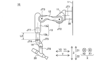
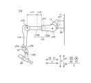
- FIG. FIG. 2 is a diagram showing the painting robot according to the first embodiment in a state where the JT7 joint is contracted.
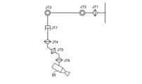
- FIG. 2 is a diagram showing joints of a painting robot according to the first embodiment.
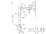
- FIG. 2 is a diagram showing the painting robot according to the first embodiment in a state where the JT7 joint is contracted.
- FIG. 1 is a block diagram of a painting robot system according to a first embodiment.
- FIG. 1 is a side view of a painting robot system according to a first embodiment.
- FIG. 2 is a diagram showing a movable range of a painting robot according to the first embodiment.
- FIG. 13 shows a painting robot according to a second embodiment in a contracted state of the JT7 joint.
- FIG. 11 is a diagram showing joints of a painting robot according to a second embodiment.
- FIG. 13 is a diagram showing a painting robot according to a second embodiment with the JT7 joint extended.
- the painting robot system 100 performs painting work on a workpiece 200.
- the workpiece 200 is, for example, a door of an automobile 210.
- the up-down direction is defined as the Z direction.
- the upper side is defined as the Z1 side
- the lower side is defined as the Z2 side.
- the direction perpendicular to the Z direction is defined as the X direction.
- One side of the X direction is defined as the X1 side, and the other side is defined as the X2 side.
- the direction perpendicular to the Z direction and the X direction is defined as the Y direction.
- One side of the Y direction is defined as the Y1 side, and the other side is defined as the Y2 side.
- the X direction is an example of a predetermined direction.
- the painting robot system 100 includes a plurality of painting robots 10.
- the painting robots 10 are arranged side by side and perform painting work on the workpiece 200.
- two painting robots 10 are arranged side by side along the X direction.
- the two painting robots 10 are attached to a wall 1 along the Z direction.
- the workpiece 200 is, for example, a door of an automobile 210.
- the painting robot 10 paints one or both of the X1 side surface and the X2 side surface of the workpiece 200.
- the workpiece 200 is transported along the X direction by a conveyor or the like.
- the painting robot 10 may paint the moving workpiece 200.
- a plurality of workpieces 200 are arranged along the X direction.
- two doors of one automobile 210 are arranged along the X direction as the workpiece 200.
- the painting robot 10 is an example of a robot.
- the configuration of the painting robot 10 will be described. Since the configurations of the two painting robots 10 are the same, the configuration of one painting robot 10 will be described.
- the painting robot 10 is a vertical multi-joint type.
- the painting robot 10 is a seven-axis vertical multi-joint type painting robot 10 including a JT1 joint, a JT2 joint, a JT3 joint, a JT4 joint, a JT5 joint, a JT6 joint, and a JT7 joint.
- the painting robot 10 includes a base unit 11, a base end arm unit 12, a tip arm unit 13, a wrist unit 14, and a robot controller 15 shown in FIG. 5.
- a painting tool 20 is connected to the tip of the painting robot 10.
- the JT7 joint is an example of a telescopic shaft of the present disclosure.
- the connection relationship between the base 11, base arm 12, tip arm 13, and wrist 14 will be described.
- the painting robot 10 is attached to a pedestal 30.
- the pedestal 30 is attached to a wall 1 along the Z direction.
- the pedestal 30 and the base 11 are connected by a JT1 joint.
- the JT1 joint rotates around an axis along the Y direction.
- the base 11 and the base end of the base arm 12 are connected by a JT2 joint.
- the JT2 joint rotates around an axis along a direction perpendicular to the axis of the JT1 joint.
- the tip of the base arm 12 and the base end of the tip arm 13 are connected by a JT3 joint.
- the JT3 joint rotates around an axis parallel to the axis of the JT2 joint.
- the tip of the tip arm 13 and the base end of the wrist 14 are connected by a JT4 joint.
- the JT4 joint rotates around an axis that is perpendicular to the axis of the JT3 joint.
- the tip of the wrist 14 and the painting tool 20 are connected by the JT6 joint.
- the JT6 joint rotates around an axis that is perpendicular to the axis of the JT3 joint.
- the JT4 joint and the JT6 joint are connected by the JT5 joint.
- the JT5 joint rotates around an axis that is perpendicular to the axis of the JT3 joint.
- a drive unit 16 shown in FIG. 5 is provided for each of the JT1 joint to the JT7 joint.
- the drive unit 16 includes a servo motor, an encoder, and a reducer.
- the JT7 joint is located on the tip arm 13 and extends and retracts the tip arm 13.
- the painting robot 10 is a 7-axis vertical multi-joint painting robot 10 having the JT7 joint as an extension axis.
- the two painting robots 10 have the same configuration, and each of the two painting robots 10 has a JT7 joint as an extension axis.
- the JT1 joint to the JT6 joint are rotary axes
- the JT7 joint is a linear axis.
- the JT7 joint includes, for example, a servo motor, and the amount of extension of the JT7 joint is adjustable.
- the tip arm section 13 has a tip arm base end portion 13a and a tip arm tip portion 13b.
- the base end of the tip arm base end portion 13a is connected to the base end arm section 12. That is, the tip arm base end portion 13a and the base end arm section 12 are connected by a JT3 joint.
- the tip of the tip arm tip portion 13b is connected to the wrist section 14 by a JT4 joint.
- the tip arm tip portion 13b is moved relative to the tip arm base end portion 13a by a JT7 joint.
- the tip arm base end portion 13a and the tip arm tip portion 13b both have a cylindrical shape.
- the tip arm tip portion 13b is inserted inside the tip arm base end portion 13a, and the tip arm tip portion 13b is inserted and removed from the tip arm base end portion 13a. This causes the tip arm section 13 to expand and contract.
- the painting robot 10 has the joints arranged in the following order from the base end to the tip end: JT1 joint, JT2 joint, JT3 joint, JT7 joint, JT4 joint, JT5 joint, and JT6 joint.
- the maximum extension amount L1 of the distal arm section 13 is greater than the length L2 of the distal arm tip portion 13b when the distal arm section 13 is in a contracted state.
- the length L2 of the distal arm tip portion 13b refers to the length of the portion of the distal arm tip portion 13b that extends beyond the distal arm base end portion 13a when the distal arm section 13 is in its most contracted state.
- the extension amount L1 of the distal arm section 13 refers to the maximum length that the distal arm tip portion 13b extends beyond the length L2.
- the robot controller 15 includes a main control unit 15a, a servo control unit 15b, and a drive circuit unit 15c.
- the main control unit 15a and the servo control unit 15b include, for example, a CPU (Central Processing Unit).
- the main control unit 15a controls the drive units 16 from the JT1 joint to the JT7 joint.
- the servo control unit 15b controls the power supplied to the drive units 16 based on instructions from the main control unit 15a.
- the drive circuit unit 15c supplies drive power to the drive units 16.
- the drive circuit unit 15c is provided for each of the JT1 joint to the JT7 joint. Note that a single common drive circuit unit 15c may be provided for the JT1 joint to the JT7 joint.
- FIG. 1 When a painting operation is performed on a workpiece 200, a plurality of painting robots 10 are positioned between the workpieces 200. Then, each of the plurality of painting robots 10 performs a painting operation on the workpiece 200 with the extension amount L1 of the JT7 joint adjusted. For example, when the painting robot 10 paints the Z1 side of the workpiece 200, the extension amount L1 of the JT7 joint is made small. Also, as shown in FIG. 6, when the painting robot 10 paints the Z2 side of the workpiece 200, the extension amount L1 of the JT7 joint is made large. That is, the extension amount L1 of the JT7 joint is adjusted according to the height of the part to be painted.
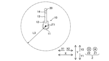
- the distance W between the painting robots 10 arranged side by side is equal to or less than the distance L3 from the axis of the JT1 joint to the end of the movable range of the painting robot 10 when the JT7 joint is retracted as shown in FIG. 7.
- the distance W between the painting robots 10 arranged side by side means the distance W in the X direction between the axes of the JT1 joints of the painting robots 10.
- the end of the movable range means, for example, the farthest end that can be reached by the point where the axis of the JT4 joint and the axis of the JT5 joint intersect in the direction away from the axis of the JT1 joint.
- the joint includes a JT7 joint that is disposed on at least one of the base arm portion 12 and the tip arm portion 13 and expands and contracts at least one of the base arm portion 12 and the tip arm portion 13.
- a JT7 joint that is disposed on at least one of the base arm portion 12 and the tip arm portion 13 and expands and contracts at least one of the base arm portion 12 and the tip arm portion 13.
- at least one of the base arm portion 12 and the tip arm portion 13 contracts, so that the overall length of at least one of the base arm portion 12 and the tip arm portion 13 is reduced. Therefore, interference between the painting robots 10 can be suppressed more effectively than when at least one of the base arm portion 12 and the tip arm portion 13 is bent.
- the painting robots 10 can be arranged closer together, so that the painting robots 10 can be arranged in a smaller arrangement area.
- the tip arm portion 13 can be extended by the JT7 joint, so that painting work can be performed on a distant workpiece 200.
- At least one of the multiple painting robots 10 includes a 7-axis vertical articulated painting robot 10 having a JT7 joint. This allows the 7-axis vertical articulated painting robots 10 to be arranged closer together in a painting robot system 100 that includes multiple 7-axis vertical articulated painting robots 10.
- Each of the multiple painting robots 10 includes a JT7 joint. This allows the seven-axis vertical articulated painting robots 10 to be arranged closer together than when only some of the multiple painting robots 10 include JT7 joints.
- Multiple workpieces 200 are arranged along the X direction, and when painting work is performed on the workpieces 200, the multiple painting robots 10 each perform painting work on the workpieces 200 with the amount of expansion and contraction of the JT7 joint adjusted between the workpieces 200. This allows the painting robots 10 to accurately perform painting work, as the amount of expansion and contraction of the JT7 joint is adjusted.
- the painting robot 10 includes a base portion 11 to which the base end of the base arm portion 12 is connected and which rotates the base arm portion 12 around the axis of the JT1 joint.
- the distance W between the painting robots 10 arranged side by side is equal to or less than the distance L3 from the axis of the JT1 joint to the end of the movable range of the painting robot 10 when the JT7 joint is in a contracted state. This reduces the distance W between the painting robots 10, so that the painting robots 10 can be arranged reliably close to each other.
- Multiple painting robots 10 are arranged along the X direction. This allows the painting robots 10 to easily perform painting work on each of the multiple workpieces 200 arranged along the X direction.
- the distal arm 13 has a distal arm base end portion 13a whose base end is connected to the base end arm 12, and a distal arm tip portion 13b whose tip is connected to the wrist portion 14 and moved relative to the distal arm base end portion 13a by the JT7 joint.
- a distal arm tip portion 13b which is a part of the distal arm portion 13 moves toward the workpiece 200. Because of this, the size of the distal arm tip portion 13b approaching the workpiece 200 is relatively small, so painting work can be performed with the distance between the distal arm tip portion 13b and the workpiece 200 relatively large. As a result, interference between the distal arm portion 13 and the workpiece 200 can be suppressed.
- the maximum extension amount L1 of the distal arm portion 13 is greater than the length L2 of the distal arm tip portion 13b when the distal arm portion 13 is retracted. This makes the extension amount L1 of the distal arm portion 13 relatively large, allowing painting work to be carried out at a more distant position.
- the configuration of a painting robot 110 according to the second embodiment will be described.
- the arrangement position of the JT7 joint is different from that of the painting robot 10 according to the first embodiment.
- the painting robot 110 is an example of a robot.
- the JT7 joint is disposed in the base arm section 112 and extends and retracts the base arm section 112.
- the base arm section 112 has a base arm base end portion 112a and a base arm tip portion 112b.
- the base end of the base arm base end portion 112a is connected to the base unit 11.
- the tip of the base arm tip portion 112b is connected to the tip arm section 13 and is moved relative to the base arm base end portion 112a by the JT7 joint.
- the base arm base end portion 112a and the base arm tip portion 112b both have a cylindrical shape.
- the base arm tip portion 112b is inserted inside the base arm base end portion 112a, and the base arm tip portion 112b is inserted and removed from the base arm base end portion 112a. This causes the base arm section 112 to extend and retract.
- the tip arm 113 of the painting robot 110 does not extend or retract.
- the painting robot 110 has the joints arranged in the following order from the base end to the tip: JT1 joint, JT2 joint, JT7 joint, JT3 joint, JT4 joint, JT5 joint, and JT6 joint.
- the extension amount L11 of the base-end arm portion 112 will be described.
- the maximum extension amount L11 of the base-end arm portion 112 is greater than the length L12 of the base-end arm tip portion 112b when the base-end arm portion 112 is in a contracted state.
- the length L12 of the base-end arm tip portion 112b refers to the length of the portion of the base-end arm tip portion 112b that extends beyond the base-end arm base portion 112a when the base-end arm portion 112 is in its most contracted state.
- the extension amount L11 of the base-end arm portion 112 refers to the maximum length that the base-end arm tip portion 112b extends beyond the length L12.
- the painting robot 110 includes a base 11 to which a base end of a base arm 112 is connected and which rotates the base arm 112 about the axis of a joint JT1.
- the base arm 112 has a base arm base portion 112a whose base end is connected to the base 11, and a base arm tip portion 112b whose tip is connected to the tip arm 13 and which is moved relative to the base arm base portion 112a by the JT7 joint.
- the JT7 joint is disposed closer to the base end of the painting robot 110, and therefore the painting robot 110 can be disposed more stably than when the JT7 joint is disposed closer to the tip of the painting robot 110.
- the maximum extension amount L11 of the base-end arm portion 112 is greater than the length L12 of the base-end arm tip portion 112b when the base-end arm portion 112 is in a contracted state. This makes the extension amount L11 of the base-end arm portion 112 relatively large, allowing painting work to be performed at a more distant position.
- a JT7 joint is disposed on each of the multiple painting robots 10, but the present disclosure is not limited to this.
- a JT7 joint may be disposed on some of the multiple painting robots 10.
- the painting robots included in the painting robot system 100 may include a mixture of 6-axis painting robots and 7-axis painting robots 10. The same applies to the painting robot 110 of the second embodiment.
- the painting robot 10 includes six joints, from JT1 joint to JT6 joint, as rotation axes, but the present disclosure is not limited to this.
- the painting robot 10 may include a number of joints other than six as rotation axes. The same applies to the painting robot 110 of the second embodiment.
- the painting robot 10 may perform painting work on the workpieces 200 arranged in front of the painting robot 10. The same applies to the painting robot 110 of the second embodiment.
- multiple painting robots 10 each perform painting work on multiple workpieces 200 arranged along the X direction, but the present disclosure is not limited to this.
- multiple painting robots 10 may perform painting work on a common workpiece 200.
- the distance W between the painting robots 10 is equal to or less than the distance L3 along a direction perpendicular to the axis of the JT1 joint from the axis of the JT1 joint to the end of the range that the painting robot 10 can reach when JT7 is in a retracted state, but the present disclosure is not limited to this.
- the distance W between the painting robots 10 may be greater than the distance L3.
- the distal arm tip portion 13b was moved relative to the distal arm base end portion 13a by the JT7 joint, but the present disclosure is not limited to this.
- the distal arm base end portion 13a may be moved relative to the distal arm tip portion 13b by the JT7 joint.
- the base arm tip portion 112b was moved relative to the base arm base end portion 112a by the JT7 joint, but for example, the base arm base end portion 112a may be moved relative to the base arm tip portion 112b by the JT7 joint.
- the maximum extension amount L1 of the distal arm portion 13 is greater than the length L2 of the distal arm tip portion 13b when the distal arm portion 13 is in a retracted state, but for example, the maximum extension amount L1 of the distal arm portion 13 may be less than the length L2 of the distal arm tip portion 13b when the distal arm portion 13 is in a retracted state.
- the maximum extension amount L11 of the base arm portion 112 is greater than the length L12 of the base arm tip portion 112b when the base arm portion 112 is in a retracted state, but for example, the maximum extension amount L11 of the base arm portion 112 may be less than the length L12 of the base arm tip portion 112b when the base arm portion 112 is in a retracted state.
- the JT7 joint includes, for example, a servo motor, and the amount of expansion and contraction of the JT7 joint is adjustable, but the present disclosure is not limited to this.
- the JT7 joint may include an air cylinder or the like, and the JT7 joint may be adjusted to only two lengths, an expanded state and a contracted state.
- the JT7 joint is disposed between the JT3 joint and the JT4 joint
- an example is shown in which the JT7 joint is disposed between the JT2 joint and the JT3 joint, but the present disclosure is not limited to this.
- the JT7 joint may be disposed between joints other than these joints.
- multiple painting robots 10 were arranged on a wall portion 1 aligned in the Z direction, but the present disclosure is not limited to this.
- multiple painting robots 10 may be arranged on a floor surface aligned in the horizontal direction. The same applies to the painting robot 110 of the second embodiment.
- the workpiece 200 is a door of the automobile 210, but the present disclosure is not limited to this.
- the workpiece 200 may be a workpiece 200 other than a door of the automobile 210.
- the JT7 joint as the telescopic shaft is disposed in the distal arm portion 13 and in the second embodiment, the JT7 joint as the telescopic shaft is disposed in the proximal arm portion 112, but the present disclosure is not limited to this.
- the telescopic shaft may be disposed in both the proximal arm portion and the distal arm portion.
- the system is equipped with multiple vertical articulated robots that perform painting work on the workpieces, At least one of the plurality of robots A base end arm portion, a distal arm portion having a proximal end connected to the proximal arm portion; A wrist portion having a base end connected to the distal arm portion and a coating tool attached to a distal end thereof; a telescopic shaft disposed on at least one of the base arm portion and the tip arm portion, the telescopic shaft extending and contracting at least one of the base arm portion and the tip arm portion.
- each of the plurality of robots includes the telescopic shaft.
- each of the plurality of robots performs a painting operation on the workpiece with the extension/retraction amount of the telescopic shaft adjusted between the workpieces.
- the robot includes a base portion to which a base end of the base end arm portion is connected and which rotates the base end arm portion around a predetermined axis;
- the distal arm portion is a tip arm base end portion having a base end connected to the base end arm section; and a tip arm tip portion having a tip connected to the wrist section and moved by the telescopic shaft relative to the tip arm base end portion.
- the painting robot includes a base portion to which a base end of the base end arm portion is connected and which rotates the base end arm portion about a predetermined axis;
- the base end arm portion is A painting robot system according to any one of claims 1 to 8, comprising: a base end of a base end arm base end portion connected to the base portion; and a base end arm tip end portion having a tip connected to the tip arm portion and moved by the telescopic shaft relative to the base end arm base end portion.
- a vertical articulated robot that performs painting work on a workpiece, The robot comprises: A base end arm portion, a distal arm portion having a proximal end connected to the proximal arm portion; A wrist portion having a base end connected to the distal arm portion and a coating tool attached to a distal end thereof; a telescopic shaft disposed on the distal arm portion and configured to extend and retract the distal arm portion.
- the distal arm portion is 12.
- the robot according to aspect 11, comprising: a tip arm base end portion having a base end connected to the base end arm section; and a tip arm tip portion having a tip connected to the wrist section and moved by the telescopic shaft relative to the tip arm base end portion.
Landscapes
- Engineering & Computer Science (AREA)
- Robotics (AREA)
- Mechanical Engineering (AREA)
- Manipulator (AREA)
- Spray Control Apparatus (AREA)
Abstract
この塗装ロボットシステム(100)では、ロボット(10)は、基端アーム部(12)と、先端アーム部(13)と、先端に塗装器具(20)が取り付けられる手首部(14)と、基端アーム部(12)と先端アーム部(13)とのうちの少なくとも一方を伸縮する伸縮軸(JT7)と、を含む。
Description
この開示は、塗装ロボットシステムおよびロボットに関する。
従来、塗装などの作業を実行するロボットが開示されている。特開2018-183843号公報には、7軸の垂直多関節ロボットが開示されている。特開2018-183843号公報の7軸の垂直多関節ロボットは、ベース部と、下部アーム部と、上部アーム部と、手首部と、を備えている。また、特開2018-183843号公報では、上部アーム部と手首部との間に、互いに屈曲する第1アームと第2アームとが配置されている。すなわち、特開2018-183843号公報の7軸の垂直多関節ロボットは、従来の6軸の垂直多関節ロボットに対して、第1アームと第2アームとを屈曲するための7軸目としての関節が追加されている。
特開2018-183843号公報に開示されている7軸の垂直多関節ロボットは、7軸目の関節を折り曲げることにより、従来の6軸の垂直多関節ロボットに比べて大きさがコンパクトになる。このため、複数の7軸の垂直多関節ロボットを配置する場合、7軸の垂直多関節ロボット同士の干渉を避けながら、7軸の垂直多関節ロボット同士を密に配置することができる。その結果、7軸の垂直多関節ロボットが配置される配置領域を小さくすることが可能になる。しかしながら、特開2018-183843号公報の7軸の垂直多関節ロボットでは、第1アームと第2アームとが屈曲する一方、第1アームと第2アームとの全長は変わらないため、7軸の垂直多関節ロボット同士の間隔を小さくしすぎると、7軸の垂直多関節ロボット同士が干渉してしまう。そこで、より小さな配置領域に配置することが可能な垂直多関節ロボットが望まれている。
この開示は、上記のような課題を解決するためになされたものであり、この開示の1つの目的は、より小さな配置領域に配置することが可能な塗装ロボットシステムおよびロボットを提供することである。
この開示の第1の局面による塗装ロボットシステムは、ワークに対して塗装作業を実行する垂直多関節型の複数のロボットを備え、複数のロボットのうちの少なくとも1つは、基端アーム部と、基端が基端アーム部に接続される先端アーム部と、基端が先端アーム部に接続され、先端に塗装器具が取り付けられる手首部と、基端アーム部と先端アーム部とのうちの少なくとも一方に配置され、基端アーム部と先端アーム部とのうちの少なくとも一方を伸縮する伸縮軸と、を含む。
この開示の第1の局面による塗装ロボットシステムは、上記のように、基端アーム部と先端アーム部とのうちの少なくとも一方に配置され、基端アーム部と先端アーム部とのうちの少なくとも一方を伸縮する伸縮軸を含む。これにより、基端アーム部と先端アーム部とのうちの少なくとも一方が縮むので、基端アーム部と先端アーム部とのうちの少なくとも一方の全長が小さくなる。このため、基端アーム部と先端アーム部とのうちの少なくとも一方が屈曲する場合と比べて、ロボット同士の干渉をより抑制できる。その結果、ロボット同士をより密に配置することができるので、より小さな配置領域にロボットを配置することができる。また、基端アーム部と先端アーム部とのうちの少なくとも一方が比較的短い場合でも、伸縮軸によって基端アーム部と先端アーム部とのうちの少なくとも一方を伸長することにより、遠方のワークに対して塗装作業を実行することができる。
この開示の第2の局面によるロボットは、ワークに対して塗装作業を実行する垂直多関節型のロボットであって、ロボットは、基端アーム部と、基端が基端アーム部に接続される先端アーム部と、基端が先端アーム部に接続され、先端に塗装器具が取り付けられる手首部と、先端アーム部に配置され、先端アーム部を伸縮する伸縮軸と、を含む。
この開示の第2の局面によるロボットは、上記のように、先端アーム部に配置され、先端アーム部を伸縮する伸縮軸を含む。これにより、先端アーム部が縮むので、先端アーム部の全長が小さくなる。このため、先端アーム部が屈曲する場合と比べて、ロボット同士の干渉をより抑制できる。その結果、ロボット同士をより密に配置することができるので、より小さな配置領域に配置可能なロボットを提供できる。
本開示によれば、塗装ロボットを、より小さな配置領域に配置することができる。
以下、本開示を具体化した本開示の一実施形態を図面に基づいて説明する。
[第1実施形態]
(塗装ロボットシステム)
第1実施形態による塗装ロボットシステム100の構成について説明する。図1に示すように、塗装ロボットシステム100は、ワーク200に対して塗装作業を実行する。ワーク200は、たとえば、自動車210のドアである。なお、本願明細書において、上下方向をZ方向とする。上方側をZ1側とし、下方側をZ2側とする。Z方向に直交する方向をX方向とする。X方向の一方側をX1側とし、他方側をX2側とする。Z方向およびX方向に直交する方向をY方向とする。Y方向の一方側をY1側とし、他方側をY2側とする。なお、X方向は、所定の方向の一例である。
(塗装ロボットシステム)
第1実施形態による塗装ロボットシステム100の構成について説明する。図1に示すように、塗装ロボットシステム100は、ワーク200に対して塗装作業を実行する。ワーク200は、たとえば、自動車210のドアである。なお、本願明細書において、上下方向をZ方向とする。上方側をZ1側とし、下方側をZ2側とする。Z方向に直交する方向をX方向とする。X方向の一方側をX1側とし、他方側をX2側とする。Z方向およびX方向に直交する方向をY方向とする。Y方向の一方側をY1側とし、他方側をY2側とする。なお、X方向は、所定の方向の一例である。
図1に示すように、塗装ロボットシステム100は、複数の塗装ロボット10を備えている。複数の塗装ロボット10は、並んで配置されており、ワーク200に対して塗装作業を実行する。図1では、2台の塗装ロボット10がX方向に沿って並んで配置されている。また、2台の塗装ロボット10は、Z方向に沿った壁部1に取り付けられている。ワーク200は、たとえば、自動車210のドアである。塗装ロボット10は、ワーク200のX1側の面とX2側の面とのうちの一方、または、両方を塗装する。ワーク200は、コンベアなどにより、X方向に沿って搬送される。塗装ロボット10によりワーク200が塗装される際には、ワーク200は停止されている。なお、塗装ロボット10は、移動するワーク200を塗装してもよい。また、ワーク200は、X方向に沿って複数配置されている。なお、図1に示す例では、1台の自動車210の2のドアが、ワーク200としてX方向に沿って2つ配置されている。なお、塗装ロボット10は、ロボットの一例である。
(塗装ロボット)
塗装ロボット10の構成について説明する。なお、2台の塗装ロボット10の構成は同様であるので、1台の塗装ロボット10の構成について説明する。図2に示すように、塗装ロボット10は、垂直多関節型である。また、塗装ロボット10は、JT1関節、JT2関節、JT3関節、JT4関節、JT5関節、JT6関節およびJT7関節を含む7軸の垂直多関節型の塗装ロボット10である。塗装ロボット10は、基台部11と、基端アーム部12と、先端アーム部13と、手首部14と、図5に示すロボットコントローラ15と、を備えている。塗装ロボット10の先端には、塗装器具20が接続されている。なお、JT7関節は、本開示の伸縮軸の一例である。
塗装ロボット10の構成について説明する。なお、2台の塗装ロボット10の構成は同様であるので、1台の塗装ロボット10の構成について説明する。図2に示すように、塗装ロボット10は、垂直多関節型である。また、塗装ロボット10は、JT1関節、JT2関節、JT3関節、JT4関節、JT5関節、JT6関節およびJT7関節を含む7軸の垂直多関節型の塗装ロボット10である。塗装ロボット10は、基台部11と、基端アーム部12と、先端アーム部13と、手首部14と、図5に示すロボットコントローラ15と、を備えている。塗装ロボット10の先端には、塗装器具20が接続されている。なお、JT7関節は、本開示の伸縮軸の一例である。
基台部11と基端アーム部12と先端アーム部13と手首部14との接続関係について説明する。塗装ロボット10は、台座30に取り付けられている。台座30は、Z方向に沿った壁部1に取り付けられている。台座30と基台部11とは、JT1関節により接続されている。図2に示す例では、JT1関節は、Y方向に沿った軸線周りに回転する。基台部11と基端アーム部12の基端とは、JT2関節により接続されている。JT2関節は、JT1関節の軸線に対して直交する方向に沿った軸線周りに回転する。基端アーム部12の先端と、先端アーム部13の基端とは、JT3関節により接続されている。JT3関節は、JT2関節の軸線と平行な軸線周りに回転する。先端アーム部13の先端と、手首部14の基端とは、JT4関節により接続されている。JT4関節は、JT3関節の軸線に対して直交する方向に沿った軸線周りに回転する。手首部14の先端と、塗装器具20とは、JT6関節により接続されている。JT6関節は、JT3関節の軸線に対して直交する方向に沿った軸線周りに回転する。また、JT4関節とJT6関節とは、JT5関節により接続されている。JT5関節は、JT3関節の軸線に対して直交する方向に沿った軸線周りに回転する。また、JT4関節の軸線とJT5関節の軸線とは、互いに交差する。また、JT5関節の軸線とJT6関節の軸線とは、互いに交差する。また、JT1関節からJT7関節までの各々に図5に示す駆動部16が配置されている。駆動部16は、サーボモータとエンコーダと減速機とを含む。
JT7関節の配置位置について説明する。第1実施形態では、JT7関節は、先端アーム部13に配置され、先端アーム部13を伸縮する。すなわち、塗装ロボット10は、伸縮軸としてのJT7関節を有する7軸の垂直多関節型の塗装ロボット10である。なお、上記のように2台の塗装ロボット10は、同様の構成を有しており、2台の塗装ロボット10は、各々、伸縮軸としてのJT7関節を有する。また、JT1関節からJT6関節までは、回転軸である一方、JT7関節は、直動軸である。JT7関節は、たとえば、サーボモータを含み、JT7関節の伸縮量は、調整可能である。
先端アーム部13の具体的な構成について説明する。第1実施形態では、図2に示すように、先端アーム部13は、先端アーム基端部分13aと、先端アーム先端部分13bと、を有する。先端アーム基端部分13aは、基端が基端アーム部12に接続されている。すなわち、先端アーム基端部分13aと基端アーム部12とは、JT3関節により接続されている。先端アーム先端部分13bの先端と、手首部14とがJT4関節により接続されている。先端アーム先端部分13bは、先端アーム基端部分13aに対してJT7関節により移動される。具体的には、先端アーム基端部分13aと先端アーム先端部分13bとは、共に筒形状を有する。そして、先端アーム先端部分13bが、先端アーム基端部分13aの内部に挿入されており、先端アーム先端部分13bが先端アーム基端部分13aに出し入れされる。これにより、先端アーム部13が伸縮する。このように、図3に示すように、塗装ロボット10では、基端から先端に向かって、JT1関節、JT2関節、JT3関節、JT7関節、JT4関節、JT5関節、および、JT6関節の順に関節が配置されている。
先端アーム部13の伸長量L1について説明する。第1実施形態では、図4に示すように、先端アーム部13の最大の伸長量L1は、先端アーム部13が縮んだ状態での先端アーム先端部分13bの長さL2よりも大きい。なお、先端アーム先端部分13bの長さL2とは、先端アーム部13が最も縮んだ状態で、先端アーム先端部分13bのうちの先端アーム基端部分13aから出ている部分の長さを意味する。また、先端アーム部13の伸長量L1とは、先端アーム先端部分13bが長さL2からさらに伸びる最大の長さを意味する。
ロボットコントローラ15について説明する。図5に示すように、ロボットコントローラ15は、メイン制御部15aと、サーボ制御部15bと、駆動回路部15cと、を含む。メイン制御部15a、および、サーボ制御部15bは、たとえば、CPU(Central Processing Unit)を含む。メイン制御部15aは、JT1関節からJT7関節までの駆動部16を制御する。サーボ制御部15bは、メイン制御部15aからの指令に基づいて、駆動部16に供給される電力を制御する。駆動回路部15cは、駆動部16に駆動電力を供給する。駆動回路部15cは、JT1関節からJT7関節までの各々に対して配置されている。なお、JT1関節からJT7関節までに対して共通の1つの駆動回路部15cを配置してもよい。
(塗装ロボットシステムのレイアウト)
塗装ロボットシステム100のレイアウトについて説明する。第1実施形態では、図1に示すように、ワーク200に対して塗装作業が実行される際に、複数の塗装ロボット10は、各々、ワーク200同士の間に位置している。そして、複数の塗装ロボット10は、各々、JT7関節の伸長量L1が調整された状態でワーク200に対して塗装作業を実行する。たとえば、塗装ロボット10がワーク200のZ1側を塗装する場合には、JT7関節の伸長量L1が小さくされる。また、図6に示すように、塗装ロボット10がワーク200のZ2側を塗装する場合には、JT7関節の伸長量L1が大きくされる。つまり、塗装する部分の高さに合わせて、JT7関節の伸長量L1が調整される。
塗装ロボットシステム100のレイアウトについて説明する。第1実施形態では、図1に示すように、ワーク200に対して塗装作業が実行される際に、複数の塗装ロボット10は、各々、ワーク200同士の間に位置している。そして、複数の塗装ロボット10は、各々、JT7関節の伸長量L1が調整された状態でワーク200に対して塗装作業を実行する。たとえば、塗装ロボット10がワーク200のZ1側を塗装する場合には、JT7関節の伸長量L1が小さくされる。また、図6に示すように、塗装ロボット10がワーク200のZ2側を塗装する場合には、JT7関節の伸長量L1が大きくされる。つまり、塗装する部分の高さに合わせて、JT7関節の伸長量L1が調整される。
塗装ロボット10同士の間隔について説明する。第1実施形態では、図1に示すように、並んで配置された塗装ロボット10同士の間隔Wは、図7に示すように、JT7関節が縮んだ状態において、JT1関節の軸線から塗装ロボット10の可動範囲の端部までの距離L3以下である。なお、並んで配置された塗装ロボット10同士の間隔Wとは、塗装ロボット10のJT1関節の軸線同士のX方向に沿った間隔Wを意味する。また、可動範囲の端部とは、たとえば、JT4関節の軸線とJT5関節の軸線とが交差する点が、JT1関節の軸線から離間する方向において到達可能な最遠端を意味する。
[第1実施形態の効果]
基端アーム部12と先端アーム部13とのうちの少なくとも一方に配置され、基端アーム部12と先端アーム部13とのうちの少なくとも一方を伸縮するJT7関節を含む。これにより、基端アーム部12と先端アーム部13とのうちの少なくとも一方が縮むので、基端アーム部12と先端アーム部13とのうちの少なくとも一方の全長が小さくなる。このため、基端アーム部12と先端アーム部13とのうちの少なくとも一方が屈曲する場合と比べて、塗装ロボット10同士の干渉をより抑制できる。その結果、塗装ロボット10同士をより密に配置することができるので、より小さな配置領域に塗装ロボット10を配置することができる。また、先端アーム部13が比較的短い場合でも、JT7関節によって先端アーム部13を伸長することにより、遠方のワーク200に対して塗装作業を実行することができる。
基端アーム部12と先端アーム部13とのうちの少なくとも一方に配置され、基端アーム部12と先端アーム部13とのうちの少なくとも一方を伸縮するJT7関節を含む。これにより、基端アーム部12と先端アーム部13とのうちの少なくとも一方が縮むので、基端アーム部12と先端アーム部13とのうちの少なくとも一方の全長が小さくなる。このため、基端アーム部12と先端アーム部13とのうちの少なくとも一方が屈曲する場合と比べて、塗装ロボット10同士の干渉をより抑制できる。その結果、塗装ロボット10同士をより密に配置することができるので、より小さな配置領域に塗装ロボット10を配置することができる。また、先端アーム部13が比較的短い場合でも、JT7関節によって先端アーム部13を伸長することにより、遠方のワーク200に対して塗装作業を実行することができる。
複数の塗装ロボット10のうちの少なくとも1つは、JT7関節を有する7軸の垂直多関節型の塗装ロボット10を含む。これにより、複数の7軸の垂直多関節型の塗装ロボット10を備える塗装ロボットシステム100において、7軸の垂直多関節型の塗装ロボット10同士をより密に配置することができる。
複数の塗装ロボット10の各々は、JT7関節を含む。これにより、複数の塗装ロボット10の一部のみがJT7関節を含む場合と比べて、7軸の垂直多関節型の塗装ロボット10同士をより一層密に配置することができる。
ワーク200は、X方向に沿って複数配置され、ワーク200に対して塗装作業が実行される際に、複数の塗装ロボット10は、各々、ワーク200同士の間においてJT7関節の伸縮量が調整された状態でワーク200に対して塗装作業を実行する。これにより、JT7関節の伸縮量が調整されるので、塗装ロボット10は、正確に塗装作業を実行することができる。
塗装ロボット10は、基端アーム部12の基端が接続され、基端アーム部12をJT1関節の軸線周りに回転させる基台部11を含む。並んで配置された塗装ロボット10同士の間隔Wは、JT7関節が縮んだ状態において、JT1関節の軸線から塗装ロボット10の可動範囲の端部までの距離L3以下である。これにより、塗装ロボット10同士の間隔Wが小さくなるので、塗装ロボット10同士を確実に密に配置することができる。
塗装ロボット10は、X方向に沿って複数配置されている。これにより、X方向に沿って複数配置されているワーク200の各々に対して、塗装ロボット10により塗装作業を容易に実行できる。
先端アーム部13は、基端が基端アーム部12に接続される先端アーム基端部分13aと、先端が手首部14に接続され先端アーム基端部分13aに対してJT7関節により移動される先端アーム先端部分13bと、を有する。これにより、基端アーム部12が伸長して先端アーム部13の全体がワーク200側に移動する場合と異なり、先端アーム部13の一部分である先端アーム先端部分13bのみがワーク200側に移動する。このため、ワーク200に近づく先端アーム先端部分13bの大きさが比較的小さいので、先端アーム先端部分13bとワーク200との間の距離を比較的大きくした状態で塗装作業を実行できる。その結果、先端アーム部13とワーク200との干渉を抑制できる。
先端アーム部13の最大の伸長量L1は、先端アーム部13が縮んだ状態での先端アーム先端部分13bの長さL2よりも大きい。これにより、先端アーム部13の伸長量L1が比較的大きくなるので、より遠い位置まで塗装作業を実行することができる。
[第2実施形態]
第2実施形態による塗装ロボット110の構成について説明する。第2実施形態による塗装ロボット110では、JT7関節の配置位置が、第1実施形態による塗装ロボット10と異なっている。なお、塗装ロボット110は、ロボットの一例である。
第2実施形態による塗装ロボット110の構成について説明する。第2実施形態による塗装ロボット110では、JT7関節の配置位置が、第1実施形態による塗装ロボット10と異なっている。なお、塗装ロボット110は、ロボットの一例である。
第2実施形態では、図8に示すように、JT7関節は、基端アーム部112に配置され、基端アーム部112を伸縮する。具体的には、基端アーム部112は、基端アーム基端部分112aと、基端アーム先端部分112bと、を有する。基端アーム基端部分112aは、基端が基台部11に接続されている。基端アーム先端部分112bは、先端が先端アーム部13に接続され基端アーム基端部分112aに対してJT7関節により移動される。具体的には、基端アーム基端部分112aと基端アーム先端部分112bとは、共に筒形状を有する。そして、基端アーム先端部分112bが、基端アーム基端部分112aの内部に挿入されており、基端アーム先端部分112bが基端アーム基端部分112aに出し入れされる。これにより、基端アーム部112が伸縮する。なお、塗装ロボット110の先端アーム部113は、伸縮しない。このように、図9に示すように、塗装ロボット110では、基端から先端に向かって、JT1関節、JT2関節、JT7関節、JT3関節、JT4関節、JT5関節、および、JT6関節の順に関節が配置されている。
基端アーム部112の伸長量L11について説明する。第2実施形態では、図10に示すように、基端アーム部112の最大の伸長量L11は、基端アーム部112が縮んだ状態での基端アーム先端部分112bの長さL12よりも大きい。なお、基端アーム先端部分112bの長さL12とは、基端アーム部112が最も縮んだ状態で、基端アーム先端部分112bのうちの基端アーム基端部分112aから出ている部分の長さを意味する。また、基端アーム部112の伸長量L11とは、基端アーム先端部分112bが長さL12からさらに伸びる最大の長さを意味する。
なお、第2実施形態のその他の構成は、上記第1実施形態と同様である。
[第2実施形態の効果]
塗装ロボット110は、基端アーム部112の基端が接続され、基端アーム部112を関節JT1の軸線周りに回転させる基台部11を含む。基端アーム部112は、基端が基台部11に接続される基端アーム基端部分112aと、先端が先端アーム部13に接続され基端アーム基端部分112aに対してJT7関節により移動される基端アーム先端部分112bと、を有する。これにより、JT7関節が塗装ロボット110の基端寄りに配置されるので、JT7関節が塗装ロボット110の先端よりに配置される場合と比べて、塗装ロボット110を安定して配置できる。
塗装ロボット110は、基端アーム部112の基端が接続され、基端アーム部112を関節JT1の軸線周りに回転させる基台部11を含む。基端アーム部112は、基端が基台部11に接続される基端アーム基端部分112aと、先端が先端アーム部13に接続され基端アーム基端部分112aに対してJT7関節により移動される基端アーム先端部分112bと、を有する。これにより、JT7関節が塗装ロボット110の基端寄りに配置されるので、JT7関節が塗装ロボット110の先端よりに配置される場合と比べて、塗装ロボット110を安定して配置できる。
基端アーム部112の最大の伸長量L11は、基端アーム部112が縮んだ状態での基端アーム先端部分112bの長さL12よりも大きい。これにより、基端アーム部112の伸長量L11が比較的大きくなるので、より遠い位置まで塗装作業を実行することができる。
[変形例]
なお、今回開示された実施形態は、すべての点で例示であって制限的なものではないと考えられるべきである。本開示の範囲は、上記した実施形態の説明ではなく請求の範囲によって示され、さらに請求の範囲と均等の意味および範囲内でのすべての変更(変形例)が含まれる。
なお、今回開示された実施形態は、すべての点で例示であって制限的なものではないと考えられるべきである。本開示の範囲は、上記した実施形態の説明ではなく請求の範囲によって示され、さらに請求の範囲と均等の意味および範囲内でのすべての変更(変形例)が含まれる。
上記第1実施形態では、複数の塗装ロボット10の各々にJT7関節が配置されている例を示したが、本開示はこれに限られない。たとえば、複数の塗装ロボット10の一部にJT7関節が配置されていてもよい。すわなち、塗装ロボットシステム100に含まれる塗装ロボットに、6軸の塗装ロボットと7軸の塗装ロボット10とが混在していてもよい。第2実施形態の塗装ロボット110についても同様である。
上記第1実施形態では、塗装ロボット10が、回転軸として、JT1関節からJT6関節までの6つの関節を含む例を示したが、本開示はこれに限られない。たとえば、塗装ロボット10が、回転軸として、6つ以外の数の関節を含んでいてもよい。第2実施形態の塗装ロボット110についても同様である。
上記第1実施形態では、ワーク200に対して塗装作業が実行される際に、複数の塗装ロボット10は、各々、ワーク200同士の間において塗装作業を実行する例を示したが、本開示はこれに限られない。たとえば、塗装ロボット10の正面に配置されたワーク200に対して、塗装ロボット10が塗装作業を実行してもよい。第2実施形態の塗装ロボット110についても同様である。
上記第1実施形態では、複数の塗装ロボット10が、各々、X方向に沿って複数配置されたワーク200の各々に塗装作業を実行する例を示したが、本開示はこれに限られない。たとえば、複数の塗装ロボット10が、共通のワーク200に対して塗装作業を実行してもよい。第2実施形態の塗装ロボット110についても同様である。
上記第1実施形態では、塗装ロボット10同士の間隔Wは、JT7が縮んだ状態において、JT1関節の軸線から塗装ロボット10が届く範囲の端部までのJT1関節の軸線に直交する方向に沿った距離L3以下である例を示したが、本開示はこれに限られない。たとえば、塗装ロボット10同士の間隔Wを、距離L3よりも大きくしてもよい。第2実施形態の塗装ロボット110についても同様である。
上記第1実施形態では、先端アーム先端部分13bが、JT7関節により、先端アーム基端部分13aに対して移動される例を示したが、本開示はこれに限られない。たとえば、先端アーム基端部分13aが、JT7関節により、先端アーム先端部分13bに対して移動されてもよい。同様に、上記第2実施形態では、基端アーム先端部分112bが、JT7関節により、基端アーム基端部分112aに対して移動される例を示したが、たとえば、基端アーム基端部分112aが、JT7関節により、基端アーム先端部分112bに対して移動されてもよい。
上記第1実施形態では、先端アーム部13の最大の伸長量L1は、先端アーム部13が縮んだ状態での先端アーム先端部分13bの長さL2よりも大きい例を示したが、たとえば、先端アーム部13の最大の伸長量L1を、先端アーム部13が縮んだ状態での先端アーム先端部分13bの長さL2以下にしてもよい。同様に、上記第2実施形態では、基端アーム部112の最大の伸長量L11は、基端アーム部112が縮んだ状態での基端アーム先端部分112bの長さL12よりも大きい例を示したが、たとえば、基端アーム部112の最大の伸長量L11を、基端アーム部112が縮んだ状態での基端アーム先端部分112bの長さL12以下にしてもよい。
上記第1および第2実施形態では、JT7関節は、たとえば、サーボモータを含み、JT7関節の伸縮量は、調整可能である例を示したが、本開示はこれに限られない。たとえば、JT7関節が、エアシリンダなど含み、JT7関節は、伸びた状態または縮んだ状態の2つの長さのみに調整されてもよい。
上記第1実施形態では、JT7関節が、JT3関節とJT4関節との間に配置され、上記第2実施形態では、JT7関節が、JT2関節とJT3関節との間に配置される例を示したが、本開示はこれに限られない。たとえば、JT7関節が、これらの関節の間以外の関節の間に配置されていてもよい。
上記第1実施形態では、複数の塗装ロボット10が、Z方向に沿った壁部1に配置される例を示したが、本開示はこれに限られない。たとえば、複数の塗装ロボット10が、水平方向に沿った床面に配置されていてもよい。第2実施形態の塗装ロボット110についても同様である。
上記第1および第2実施形態では、ワーク200が自動車210のドアである例を示したが、本開示はこれに限られない。たとえば、ワーク200が自動車210のドア以外のワーク200であってもよい。
上記第1実施形態では、伸縮軸としてのJT7関節が先端アーム部13に配置され、上記第2実施形態では、伸縮軸としてのJT7関節が基端アーム部112に配置される例を示したが、本開示はこれに限られない。たとえば、伸縮軸が、基端アーム部および先端アーム部の両方に配置されていてもよい。
[態様]
上記した例示的な実施形態は、以下の態様の具体例であることが当業者により理解される。
上記した例示的な実施形態は、以下の態様の具体例であることが当業者により理解される。
(態様1)
ワークに対して塗装作業を実行する垂直多関節型の複数のロボットを備え、
前記複数のロボットのうちの少なくとも1つは、
基端アーム部と、
基端が前記基端アーム部に接続される先端アーム部と、
基端が前記先端アーム部に接続され、先端に塗装器具が取り付けられる手首部と、
前記基端アーム部と前記先端アーム部とのうちの少なくとも一方に配置され、前記基端アーム部と前記先端アーム部とのうちの少なくとも一方を伸縮する伸縮軸と、を含む、塗装ロボットシステム。
ワークに対して塗装作業を実行する垂直多関節型の複数のロボットを備え、
前記複数のロボットのうちの少なくとも1つは、
基端アーム部と、
基端が前記基端アーム部に接続される先端アーム部と、
基端が前記先端アーム部に接続され、先端に塗装器具が取り付けられる手首部と、
前記基端アーム部と前記先端アーム部とのうちの少なくとも一方に配置され、前記基端アーム部と前記先端アーム部とのうちの少なくとも一方を伸縮する伸縮軸と、を含む、塗装ロボットシステム。
(態様2)
前記複数のロボットのうちの少なくとも1つは、前記伸縮軸を有する7軸の垂直多関節型のロボットを含む、態様1に記載の塗装ロボットシステム。
前記複数のロボットのうちの少なくとも1つは、前記伸縮軸を有する7軸の垂直多関節型のロボットを含む、態様1に記載の塗装ロボットシステム。
(態様3)
前記複数のロボットの各々は、前記伸縮軸を含む、態様1または態様2に記載の塗装ロボットシステム。
前記複数のロボットの各々は、前記伸縮軸を含む、態様1または態様2に記載の塗装ロボットシステム。
(態様4)
前記ワークは、所定の方向に沿って複数配置され、
前記ワークに対して塗装作業が実行される際に、前記複数のロボットは、各々、前記ワーク同士の間において前記伸縮軸の伸縮量が調整された状態で前記ワークに対して塗装作業を実行する、態様3に記載の塗装ロボットシステム。
前記ワークは、所定の方向に沿って複数配置され、
前記ワークに対して塗装作業が実行される際に、前記複数のロボットは、各々、前記ワーク同士の間において前記伸縮軸の伸縮量が調整された状態で前記ワークに対して塗装作業を実行する、態様3に記載の塗装ロボットシステム。
(態様5)
前記ロボットは、前記基端アーム部の基端が接続され、前記基端アーム部を所定の軸線周りに回転させる基台部を含み、
並んで配置された前記ロボット同士の間隔は、前記伸縮軸が縮んだ状態において、前記所定の軸線から前記ロボットの可動範囲の端部までの距離以下である、態様4に記載の塗装ロボットシステム。
前記ロボットは、前記基端アーム部の基端が接続され、前記基端アーム部を所定の軸線周りに回転させる基台部を含み、
並んで配置された前記ロボット同士の間隔は、前記伸縮軸が縮んだ状態において、前記所定の軸線から前記ロボットの可動範囲の端部までの距離以下である、態様4に記載の塗装ロボットシステム。
(態様6)
前記ロボットは、前記所定の方向に沿って複数配置されている、態様4または態様5に記載の塗装ロボットシステム。
前記ロボットは、前記所定の方向に沿って複数配置されている、態様4または態様5に記載の塗装ロボットシステム。
(態様7)
前記先端アーム部は、
基端が前記基端アーム部に接続される先端アーム基端部分と、先端が前記手首部に接続され前記先端アーム基端部分に対して前記伸縮軸により移動される先端アーム先端部分と、を有する、態様1から態様6までのいずれか1項に記載の塗装ロボットシステム。
前記先端アーム部は、
基端が前記基端アーム部に接続される先端アーム基端部分と、先端が前記手首部に接続され前記先端アーム基端部分に対して前記伸縮軸により移動される先端アーム先端部分と、を有する、態様1から態様6までのいずれか1項に記載の塗装ロボットシステム。
(態様8)
前記先端アーム部の最大の伸長量は、前記先端アーム部が縮んだ状態での前記先端アーム先端部分の長さよりも大きい、態様7に記載の塗装ロボットシステム。
前記先端アーム部の最大の伸長量は、前記先端アーム部が縮んだ状態での前記先端アーム先端部分の長さよりも大きい、態様7に記載の塗装ロボットシステム。
(態様9)
前記塗装ロボットは、前記基端アーム部の基端が接続され、前記基端アーム部を所定の軸線周りに回転させる基台部を含み、
前記基端アーム部は、
基端が前記基台部に接続される基端アーム基端部分と、先端が前記先端アーム部に接続され前記基端アーム基端部分に対して前記伸縮軸により移動される基端アーム先端部分と、を有する、態様1から態様8までのいずれか1項に記載の塗装ロボットシステム。
前記塗装ロボットは、前記基端アーム部の基端が接続され、前記基端アーム部を所定の軸線周りに回転させる基台部を含み、
前記基端アーム部は、
基端が前記基台部に接続される基端アーム基端部分と、先端が前記先端アーム部に接続され前記基端アーム基端部分に対して前記伸縮軸により移動される基端アーム先端部分と、を有する、態様1から態様8までのいずれか1項に記載の塗装ロボットシステム。
(態様10)
前記基端アーム部の最大の伸長量は、前記基端アーム部が縮んだ状態での前記基端アーム先端部分の長さよりも大きい、態様9に記載の塗装ロボットシステム。
前記基端アーム部の最大の伸長量は、前記基端アーム部が縮んだ状態での前記基端アーム先端部分の長さよりも大きい、態様9に記載の塗装ロボットシステム。
(態様11)
ワークに対して塗装作業を実行する垂直多関節型のロボットであって、
前記ロボットは、
基端アーム部と、
基端が前記基端アーム部に接続される先端アーム部と、
基端が前記先端アーム部に接続され、先端に塗装器具が取り付けられる手首部と、
前記先端アーム部に配置され、前記先端アーム部を伸縮する伸縮軸と、を含む、ロボット。
ワークに対して塗装作業を実行する垂直多関節型のロボットであって、
前記ロボットは、
基端アーム部と、
基端が前記基端アーム部に接続される先端アーム部と、
基端が前記先端アーム部に接続され、先端に塗装器具が取り付けられる手首部と、
前記先端アーム部に配置され、前記先端アーム部を伸縮する伸縮軸と、を含む、ロボット。
(態様12)
前記先端アーム部は、
基端が前記基端アーム部に接続される先端アーム基端部分と、先端が前記手首部に接続され前記先端アーム基端部分に対して前記伸縮軸により移動される先端アーム先端部分と、を有する、態様11に記載のロボット。
前記先端アーム部は、
基端が前記基端アーム部に接続される先端アーム基端部分と、先端が前記手首部に接続され前記先端アーム基端部分に対して前記伸縮軸により移動される先端アーム先端部分と、を有する、態様11に記載のロボット。
(態様13)
前記先端アーム先端部分の最大の伸長量は、前記先端アーム部が縮んだ状態での前記先端アーム先端部分の長さよりも大きい、態様12に記載のロボット。
前記先端アーム先端部分の最大の伸長量は、前記先端アーム部が縮んだ状態での前記先端アーム先端部分の長さよりも大きい、態様12に記載のロボット。
Claims (13)
- ワークに対して塗装作業を実行する垂直多関節型の複数のロボットを備え、
前記複数のロボットのうちの少なくとも1つは、
基端アーム部と、
基端が前記基端アーム部に接続される先端アーム部と、
基端が前記先端アーム部に接続され、先端に塗装器具が取り付けられる手首部と、
前記基端アーム部と前記先端アーム部とのうちの少なくとも一方に配置され、前記基端アーム部と前記先端アーム部とのうちの少なくとも一方を伸縮する伸縮軸と、を含む、塗装ロボットシステム。 - 前記複数のロボットのうちの少なくとも1つは、前記伸縮軸を有する7軸の垂直多関節型のロボットを含む、請求項1に記載の塗装ロボットシステム。
- 前記複数のロボットの各々は、前記伸縮軸を含む、請求項1に記載の塗装ロボットシステム。
- 前記ワークは、所定の方向に沿って複数配置され、
前記ワークに対して塗装作業が実行される際に、前記複数のロボットは、各々、前記ワーク同士の間において前記伸縮軸の伸縮量が調整された状態で前記ワークに対して塗装作業を実行する、請求項3に記載の塗装ロボットシステム。 - 前記ロボットは、前記基端アーム部の基端が接続され、前記基端アーム部を所定の軸線周りに回転させる基台部を含み、
並んで配置された前記ロボット同士の間隔は、前記伸縮軸が縮んだ状態において、前記所定の軸線から前記ロボットの可動範囲の端部までの距離以下である、請求項4に記載の塗装ロボットシステム。 - 前記ロボットは、前記所定の方向に沿って複数配置されている、請求項4に記載の塗装ロボットシステム。
- 前記先端アーム部は、
基端が前記基端アーム部に接続される先端アーム基端部分と、先端が前記手首部に接続され前記先端アーム基端部分に対して前記伸縮軸により移動される先端アーム先端部分と、を有する、請求項1に記載の塗装ロボットシステム。 - 前記先端アーム部の最大の伸長量は、前記先端アーム部が縮んだ状態での前記先端アーム先端部分の長さよりも大きい、請求項7に記載の塗装ロボットシステム。
- 前記ロボットは、前記基端アーム部の基端が接続され、前記基端アーム部を所定の軸線周りに回転させる基台部を含み、
前記基端アーム部は、
基端が前記基台部に接続される基端アーム基端部分と、先端が前記先端アーム部に接続され前記基端アーム基端部分に対して前記伸縮軸により移動される基端アーム先端部分と、を有する、請求項1に記載の塗装ロボットシステム。 - 前記基端アーム部の最大の伸長量は、前記基端アーム部が縮んだ状態での前記基端アーム先端部分の長さよりも大きい、請求項9に記載の塗装ロボットシステム。
- ワークに対して塗装作業を実行する垂直多関節型のロボットであって、
前記ロボットは、
基端アーム部と、
基端が前記基端アーム部に接続される先端アーム部と、
基端が前記先端アーム部に接続され、先端に塗装器具が取り付けられる手首部と、
前記先端アーム部に配置され、前記先端アーム部を伸縮する伸縮軸と、を含む、ロボット。 - 前記先端アーム部は、
基端が前記基端アーム部に接続される先端アーム基端部分と、先端が前記手首部に接続され前記先端アーム基端部分に対して前記伸縮軸により移動される先端アーム先端部分と、を有する、請求項11に記載のロボット。 - 前記先端アーム先端部分の最大の伸長量は、前記先端アーム部が縮んだ状態での前記先端アーム先端部分の長さよりも大きい、請求項12に記載のロボット。
Applications Claiming Priority (2)
| Application Number | Priority Date | Filing Date | Title |
|---|---|---|---|
| JP2023094686A JP2024176256A (ja) | 2023-06-08 | 2023-06-08 | 塗装ロボットシステムおよびロボット |
| JP2023-094686 | 2023-06-08 |
Publications (1)
| Publication Number | Publication Date |
|---|---|
| WO2024253015A1 true WO2024253015A1 (ja) | 2024-12-12 |
Family
ID=93795902
Family Applications (1)
| Application Number | Title | Priority Date | Filing Date |
|---|---|---|---|
| PCT/JP2024/019856 Ceased WO2024253015A1 (ja) | 2023-06-08 | 2024-05-30 | 塗装ロボットシステムおよびロボット |
Country Status (2)
| Country | Link |
|---|---|
| JP (1) | JP2024176256A (ja) |
| WO (1) | WO2024253015A1 (ja) |
Citations (3)
| Publication number | Priority date | Publication date | Assignee | Title |
|---|---|---|---|---|
| JP2007044839A (ja) * | 2005-08-11 | 2007-02-22 | Toshiba Mach Co Ltd | 産業用ロボット |
| JP2018183843A (ja) * | 2017-04-26 | 2018-11-22 | 株式会社安川電機 | ロボット |
| WO2021009903A1 (ja) * | 2019-07-18 | 2021-01-21 | 株式会社安川電機 | ロボットシステム、ロボットの制御方法、サーボシステム |
-
2023
- 2023-06-08 JP JP2023094686A patent/JP2024176256A/ja active Pending
-
2024
- 2024-05-30 WO PCT/JP2024/019856 patent/WO2024253015A1/ja not_active Ceased
Patent Citations (3)
| Publication number | Priority date | Publication date | Assignee | Title |
|---|---|---|---|---|
| JP2007044839A (ja) * | 2005-08-11 | 2007-02-22 | Toshiba Mach Co Ltd | 産業用ロボット |
| JP2018183843A (ja) * | 2017-04-26 | 2018-11-22 | 株式会社安川電機 | ロボット |
| WO2021009903A1 (ja) * | 2019-07-18 | 2021-01-21 | 株式会社安川電機 | ロボットシステム、ロボットの制御方法、サーボシステム |
Also Published As
| Publication number | Publication date |
|---|---|
| JP2024176256A (ja) | 2024-12-19 |
Similar Documents
| Publication | Publication Date | Title |
|---|---|---|
| JP5418545B2 (ja) | 塗装システム | |
| JP7590998B2 (ja) | ロボット装置 | |
| EP3231562B1 (en) | Automatic production system | |
| CN107835728B (zh) | 涂覆设备机器人、特别是操纵机器人 | |
| US20110064554A1 (en) | Robot manipulator and robot system | |
| KR101182600B1 (ko) | 실린더 형태의 큰 작업영역을 갖는 병렬형 로봇기구 | |
| KR101486098B1 (ko) | 다관절 용접 로봇 | |
| CN112405519A (zh) | 上下料机器人运动轨迹规划方法 | |
| EP1688194A3 (en) | Bending device | |
| JP2010099787A (ja) | ロボット | |
| CN105899334A (zh) | 加工装置以及工件的生产方法 | |
| KR102603904B1 (ko) | 로봇 장치 | |
| JP2024176256A (ja) | 塗装ロボットシステムおよびロボット | |
| JP7481941B2 (ja) | ロボットおよびロボットシステム | |
| CN119188793A (zh) | 涂装机器人 | |
| KR101812026B1 (ko) | 6축 다관절 로봇 | |
| JP6268924B2 (ja) | ロボット、およびロボットの作業方法 | |
| JP3638676B2 (ja) | ベンディング用6軸垂直多関節型ロボット | |
| JP2017007053A (ja) | ロボットセル装置 | |
| US12434394B2 (en) | Micromanipulator | |
| JP2026038453A (ja) | 多関節型ロボット | |
| KR101201760B1 (ko) | 매니퓰레이터 | |
| JP7001352B2 (ja) | ロボット | |
| Zhang | Programming method of a robot to cut automotive upholsteries | |
| JP2025018823A (ja) | ロボットシステム |
Legal Events
| Date | Code | Title | Description |
|---|---|---|---|
| 121 | Ep: the epo has been informed by wipo that ep was designated in this application |
Ref document number: 24819246 Country of ref document: EP Kind code of ref document: A1 |
|
| NENP | Non-entry into the national phase |
Ref country code: DE |
|
| 122 | Ep: pct application non-entry in european phase |
Ref document number: 24819246 Country of ref document: EP Kind code of ref document: A1 |