WO2024252954A1 - 運動案内装置 - Google Patents
運動案内装置 Download PDFInfo
- Publication number
- WO2024252954A1 WO2024252954A1 PCT/JP2024/019175 JP2024019175W WO2024252954A1 WO 2024252954 A1 WO2024252954 A1 WO 2024252954A1 JP 2024019175 W JP2024019175 W JP 2024019175W WO 2024252954 A1 WO2024252954 A1 WO 2024252954A1
- Authority
- WO
- WIPO (PCT)
- Prior art keywords
- path
- ball passing
- rolling
- turning
- balls
- Prior art date
- Legal status (The legal status is an assumption and is not a legal conclusion. Google has not performed a legal analysis and makes no representation as to the accuracy of the status listed.)
- Ceased
Links
Images






Classifications
-
- F—MECHANICAL ENGINEERING; LIGHTING; HEATING; WEAPONS; BLASTING
- F16—ENGINEERING ELEMENTS AND UNITS; GENERAL MEASURES FOR PRODUCING AND MAINTAINING EFFECTIVE FUNCTIONING OF MACHINES OR INSTALLATIONS; THERMAL INSULATION IN GENERAL
- F16C—SHAFTS; FLEXIBLE SHAFTS; ELEMENTS OR CRANKSHAFT MECHANISMS; ROTARY BODIES OTHER THAN GEARING ELEMENTS; BEARINGS
- F16C19/00—Bearings with rolling contact, for exclusively rotary movement
- F16C19/02—Bearings with rolling contact, for exclusively rotary movement with bearing balls essentially of the same size in one or more circular rows
- F16C19/04—Bearings with rolling contact, for exclusively rotary movement with bearing balls essentially of the same size in one or more circular rows for radial load mainly
- F16C19/08—Bearings with rolling contact, for exclusively rotary movement with bearing balls essentially of the same size in one or more circular rows for radial load mainly with two or more rows of balls
-
- F—MECHANICAL ENGINEERING; LIGHTING; HEATING; WEAPONS; BLASTING
- F16—ENGINEERING ELEMENTS AND UNITS; GENERAL MEASURES FOR PRODUCING AND MAINTAINING EFFECTIVE FUNCTIONING OF MACHINES OR INSTALLATIONS; THERMAL INSULATION IN GENERAL
- F16C—SHAFTS; FLEXIBLE SHAFTS; ELEMENTS OR CRANKSHAFT MECHANISMS; ROTARY BODIES OTHER THAN GEARING ELEMENTS; BEARINGS
- F16C29/00—Bearings for parts moving only linearly
- F16C29/04—Ball or roller bearings
- F16C29/06—Ball or roller bearings in which the rolling bodies circulate partly without carrying load
-
- F—MECHANICAL ENGINEERING; LIGHTING; HEATING; WEAPONS; BLASTING
- F16—ENGINEERING ELEMENTS AND UNITS; GENERAL MEASURES FOR PRODUCING AND MAINTAINING EFFECTIVE FUNCTIONING OF MACHINES OR INSTALLATIONS; THERMAL INSULATION IN GENERAL
- F16C—SHAFTS; FLEXIBLE SHAFTS; ELEMENTS OR CRANKSHAFT MECHANISMS; ROTARY BODIES OTHER THAN GEARING ELEMENTS; BEARINGS
- F16C33/00—Parts of bearings; Special methods for making bearings or parts thereof
- F16C33/30—Parts of ball or roller bearings
- F16C33/58—Raceways; Race rings
Definitions
- the present invention relates to a motion guide device that guides the linear motion of a movable body.
- the motion guide device comprises a track member and a carriage that is attached to the track member via a number of balls so that it can move linearly.
- the track member is attached to a fixed body such as a base.
- the carriage is attached to a movable body such as a table. The linear motion of the movable body relative to the fixed body is guided by the motion guide device.
- the track member is formed with a rolling section along which the balls roll.
- the carriage is also formed with a rolling section along which the balls roll.
- the circulation path includes a rolling path between the rolling part of the track member and the rolling part of the carriage, and a turn path and return path provided on the carriage. When the carriage moves linearly along the track member, the balls roll on the rolling path and circulate in the circulation path.
- two rows of balls may be arranged in a staggered pattern in the first and second ball passing sections of the circulation path. By having the two rows of balls alternately enter and exit the rolling path, it is possible to reduce waving.
- the positions of the two rows of balls can be determined. However, if the two rows of balls are not held by a retainer band, the positions of the two rows of balls cannot be determined. This causes the balls in the first ball passing section to overtake the balls in the second ball passing section on the turning path, making it difficult to obtain a motion guide device with smooth movement.
- the present invention was made in consideration of the above problems, and aims to provide a motion guide device with smooth movement in which two rows of balls are not held by a retainer band.
- one aspect of the present invention is a motion guide device that includes a track member having a rolling part, and a carriage having a rolling part facing the rolling part, a return path, and a turning path, and in which two rows of balls are arranged in adjacent first and second ball passing parts of a circulation path including the rolling path between the rolling part of the track member and the rolling part of the carriage, the return path, and the turning path, the two rows of balls are not held by a retainer band, and when viewed from a direction perpendicular to a plane including the rolling path and the return path, the first ball passing trajectory of the first ball passing part is arranged outside the second ball passing trajectory of the second ball passing part at the end of the turning path on the rolling path side and the end of the returning path side, and the first ball passing trajectory is arranged inside the second ball passing trajectory at the top of the turning path, and the perimeter of the first ball passing trajectory of the turning path and the perimeter of the second ball passing trajectory of the turning path are set to be substantially the same.
- the first ball passing trajectory and the second ball passing trajectory on the turning path are configured as described above, making it possible to provide a motion guide device with smooth movement.
- FIG. 1 is a perspective view (including a partial cross section) of a motion guide device according to a first embodiment of the present invention
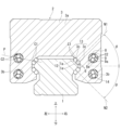
- 3 is a perpendicular cross-sectional view of a track member of the motion guide device of the present embodiment.
- FIG. FIG. 3(a) is a perpendicular cross-sectional view of the rolling path of the motion guide device of this embodiment
- FIG. 3(b) is a perpendicular cross-sectional view of the return path
- FIG. 3(c) is a perpendicular cross-sectional view of the turning path.
- FIG. 2 is a perspective view of an inner plate of the motion guide device of the present embodiment.
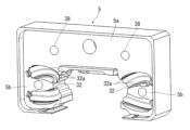
- 2 is a perspective view of an end plate of the motion guide device of the present embodiment.
- FIG. 6(a) is a perspective view showing two rows of balls arranged on a turning path of the motion guide device of this embodiment
- FIG. 6(b) is a diagram showing a first ball passing trajectory and a second ball passing trajectory on the turning path.
- FIG. 7(a) is a plan view of a turning road of the motion guide device of this embodiment
- FIG. 7(b) is a front view of the turning road
- FIG. 7(c) is a side view of the turning road.
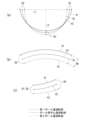
- 8(a), (b), and (c) are diagrams showing the first ball passing trajectory and the second ball passing trajectory as viewed from the same direction as FIG. 7(a), (b), and (c).
- FIG. 10(a) is a diagram showing the transmission of force of a ball on a turning road of the motion guide device of this embodiment
- FIG. 10(b) is a diagram showing the transmission of force of a ball on a turning road of a comparative example.
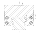
- FIG. 6 is a perpendicular cross-sectional view of a track member of a motion guide device according to a second embodiment of the present invention.
- FIG. 12(a) is a perpendicular cross-sectional view of the rolling path of a motion guide device of a second embodiment of the present invention
- FIG. 12(b) is a perpendicular cross-sectional view of the return path
- FIG. 12(c) is a perpendicular cross-sectional view of the turning path.
- FIGS. 1 to 3 show a motion guide device according to a first embodiment of the present invention.
- FIG. 1 shows a perspective view of the motion guide device.
- FIG. 2 shows a perpendicular cross-sectional view of a track member of the motion guide device.
- FIG. 3 shows an enlarged cross-sectional view of the rolling path, return path, and turning path of the motion guide device.
- the configuration of the motion guide device will be explained using the directions when the motion guide device arranged on a horizontal plane is viewed from the relative movement direction of the carriage 2, that is, the up/down, left/right, and front/back directions in Figures 1 and 2.
- the arrangement of the motion guide device is not limited to this.
- the motion guide device includes a track member 1 and a carriage 2.
- the track member 1 is attached to a base or the like (not shown).
- the carriage 2 is attached to a table or the like (not shown).
- the carriage 2 is capable of linear motion along the track member 1.
- a large number of balls 6 are interposed between the track member 1 and the carriage 2.
- the carriage 2 is provided with a circulation path 7 for circulating the large number of balls 6.
- the circulation path 7 includes a rolling path C1 between the rolling part 12 of the track member 1 and the rolling part 13 of the carriage 2, and a return path C2 and a turn path C3 provided in the carriage 2.
- Two rows of balls 6 are arranged in the circulation path 7.
- the two rows of balls 6 are not held by a retainer band.
- the two rows of balls 6 roll under load.
- the two rows of balls 6 move while being pushed by the following balls 6.
- the track member 1 is rail-shaped.
- four rolling sections 12 are formed on the track member 1.
- Protrusions 11 that protrude in the left-right direction are formed on the left and right sides of the upper part of the track member 1.
- the rolling sections 12 are formed above and below the protrusions 11 so as to sandwich the protrusions 11.
- the rolling sections 12 have two rolling grooves 1a in which two rows of balls 6 roll.
- the rolling grooves 1a are circular arc grooves whose cross section is, for example, a single arc.
- the track member 1 is provided with mounting holes 1b for mounting the track member 1 to a base or the like.
- the carriage 2 comprises a carriage body 3, an inner plate 4 attached to both end faces of the carriage body 3, and an end plate 5 attached to both end faces of the carriage body 3 so as to cover the inner plate 4.
- a return path C2 is provided in the carriage body 3.
- a roughly U-shaped turn path C3 is formed between the inner plate 4 and the end plate 5.
- the carriage body 3 has a central portion 3a that faces the upper surface of the track member 1, and left and right sleeve portions 3b that face the side surfaces of the track member 1.
- a rolling portion 13 that faces the rolling portion 12 of the track member 1 is formed on the sleeve portions 3b of the carriage body 3.
- the rolling portion 13 has two rolling grooves 3c in which two rows of balls 6 roll.
- the rolling groove 3c is a circular arc groove whose cross section is, for example, a single arc.
- a linear rolling path C1 is formed that extends in the longitudinal direction of the track member 1.
- the rolling path C1 has adjacent first and second ball passing parts 21 and 22.
- Two rows of balls 6 are arranged in a staggered pattern in the first and second ball passing parts 21 and 22. When viewed from the direction in which the balls 6 travel, adjacent balls 6 partially overlap.
- the balls 6 roll while receiving a load.
- the symbol ⁇ in Figure 2 is a contact angle that indicates the direction in which the balls 6 receive a load.
- the contact angle ⁇ is set to, for example, 30 to 60°.
- through holes 14 are formed above and below the left and right sleeves 3b of the carriage body 3, parallel to the rolling path C1.
- Two half pipes 8, 9 are inserted into the through holes 14.
- Two track surfaces 8a, 9a with arc-shaped cross sections are formed in each half pipe 8, 9.
- a return path C2 is formed between the track surface 8a of the half pipe 8 and the track surface 9a of the half pipe 9, extending in the length direction of the track member 1.
- the return path C2 is linear and parallel to the rolling path C1.
- the return path C2 is positioned offset from the direction of the contact angle line N1.
- the upper return path C2 is positioned below the contact angle line N1 of the upper ball 6.
- the lower return path C2 is positioned above the contact angle line N2 of the lower ball 6. This allows the carriage 2 to be made more compact.
- the return path C2 has a first ball passing section 21 and a second ball passing section 22 adjacent to each other.
- the perpendicular cross section of the return path C2 is gourd-shaped, and the first ball passing section 21 and the second ball passing section 22 of the return path C2 are based on two imaginary circles that partially overlap each other.
- Two rows of balls 6 are arranged in a staggered pattern in the first ball passing section 21 and the second ball passing section 22. Adjacent balls 6 partially overlap when viewed from the direction in which the balls 6 travel.
- the balls 6 move while being pushed by the following balls 6. A gap is left between the balls 6 and the first ball passing section 21, and a gap is left between the balls 6 and the second ball passing section 22.
- the inner plate 4 has a central portion 4a facing the top surface of the track member 1, and a pair of left and right sleeve portions 4b facing the side surfaces of the track member 1.
- R piece portions 31 having a roughly semi-cylindrical shape are formed above and below the left and right sleeve portions 4b of the inner plate 4.
- Two track surfaces 31a having an arc-shaped cross section are formed on the outer periphery of the R piece portion 31.
- reference numeral 31b denotes two rolling grooves connected to the two rolling grooves 3c of the carriage body 3, which face the two rolling grooves 1a of the track member 1 and function as rolling portions.
- the radius of the arc of the cross section of the rolling groove 31b may be made larger than that of the rolling groove 3c, or a step may be provided between the rolling grooves 31b and 3c, so that the load received by the ball 6 rolling in the rolling groove 31b is reduced or eliminated.
- reference numeral 31c denotes the end of the track surface 31a on the rolling path C1 side, i.e., the end of the turn path C3 on the rolling path C1 side.
- Reference numeral 31d denotes the end of the track surface 31a on the return path C2 side, i.e., the end of the turn path C3 on the return path C2 side.
- the end plate 5 also has a central portion 5a facing the top surface of the track member 1, and a pair of left and right sleeve portions 5b facing the side surfaces of the track member 1.
- Recesses 32 into which the R piece portion 31 fits are formed above and below the left and right sleeve portions 5b of the end plate 5.
- Two track surfaces 32a with arc-shaped cross sections are formed in the recess 32.
- a roughly U-shaped turning path C3 is formed between the track surface 31a of the R piece portion 31 of the inner plate 4 and the track surface 32a of the recess 32 of the end plate 5.
- the end plate 5 and the inner plate 4 are attached to the carriage body 3 by screws. Through holes 37, 38 for screws are formed in the end plate 5 and the inner plate 4.
- FIG. 3(c) shows a right-angled cross section of the turning path C3 at the top of the turning path C3.
- Reference numeral 4 denotes an inner piece
- reference numeral 5 denotes an end piece.
- the turning path C3 has a first ball passing section 21 and a second ball passing section 22 adjacent to each other.
- the right-angled cross section of the turning path C3 is gourd-shaped, and the first ball passing section 21 and the second ball passing section 22 are based on two imaginary circles that partially overlap each other.
- two rows of balls 6 are arranged in a staggered pattern. When viewed from the traveling direction of the balls 6, adjacent balls 6 partially overlap each other.
- the balls 6 move while being pushed by the following balls 6, as in the return path C2.
- a gap is left between the balls 6 and the first ball passing section 21, and a gap is left between the balls 6 and the second ball passing section 22.
- Figure 6(a) shows two rows of balls 6 arranged on the turning path C3.
- Figure 6(a) shows an oblique view of the turning path C3 of the circulating path 7 in the upper left of Figure 2.
- Reference numeral 1 denotes a track member
- reference numeral 4 denotes an inner plate
- reference numeral C3 denotes a turning path.
- Figure 6(b) shows the first ball passing trajectory 41 and the second ball passing trajectory 42 of the first ball passing section 21 of the turning path C3.
- the first ball passing trajectory 41 of the turning path C3 is represented by the center of the first ball passing section 21.
- the second ball passing trajectory 42 of the turning path C3 is represented by the center of the second ball passing section 22 of the turning path C3.
- the first ball passing trajectory and the second ball passing trajectory of the turning path are two-dimensional trajectories, whereas in the motion guide device of this embodiment, the first ball passing trajectory 41 and the second ball passing trajectory 42 of the turning path C3 are three-dimensional trajectories as described below.
- the reference number 43 in FIG. 6(b) indicates the ball center passing trajectory.
- Figure 7(a) shows the turning path C3 as viewed from a direction perpendicular to the plane P (the plane P including the center between the balls of the rolling path C1 and the center between the balls of the return path C2, see Figure 2) that contains the rolling path C1 and the return path C2.
- Figure 7(b) shows a front view of the turning path C3.
- Figure 7(c) shows a side view of the turning path C3.
- Figures 8(a), (b), and (c) show the first ball passing trajectory 41, the second ball passing trajectory 42, and the ball center trajectory 43 as viewed from the same direction as Figures 7(a), (b), and (c).
- the first ball passing trajectory 41 is positioned outward of the second ball passing trajectory 42 at the end Q1 on the rolling path C1 side and the end Q2 on the return path C2 side of the turning path C3.
- the inter-point distance L1 between the end Q1 and the end Q2 is greater for the first ball passing trajectory 41 than for the second ball passing trajectory 42.
- the first ball passing trajectory 41 is positioned inward of the second ball passing trajectory 42.
- the protruding distance L2 between the apex Q3 of the first ball passing trajectory 41 and the second ball passing trajectory 42 is smaller for the first ball passing trajectory 41 than for the second ball passing trajectory 42.
- the first ball passing trajectory 41 and the second ball passing trajectory 42 are curved upwardly convexly.
- the first ball passing trajectory 41 and the second ball passing trajectory 42 are curved upwardly from the ends Q1, Q2 toward the apex Q3 of the turning path C3.
- the circumference of the first ball passing trajectory 41 and the circumference of the second ball passing trajectory 42 of the turning path C3 are set to be substantially the same.
- the first ball passing trajectory 41 and the second ball passing trajectory 42 of the turning path C3 are set, for example, as follows.
- a rectangular virtual plate VP is prepared in which the length M1 of the short sides 61a and 61b is set to the distance M1 (see FIG. 8(b)) between the first ball passing trajectory 41 and the second ball passing trajectory 42 of the turning path C3, and the length M2 of the long sides 62a and 62b is set to the perimeter of the first ball passing trajectory 41 and the second ball passing trajectory 42 of the turning path C3.
- the short side 61a of this virtual plate VP is aligned with the end Q1 on the rolling path C1 side of the turning path C3, and the short side 61b is aligned with the end Q2 on the return path C2 side of the turning path C3, and the virtual plate VP is curved along the turning path C3.
- the shape of the long side 62a of the virtual plate VP at this time is set to the first ball passing trajectory 41 of the turning path C3, and the shape of the long side 62b is set to the second ball passing trajectory 42 of the turning path C3.
- the shape of the virtual plate VP when it is curved along the turning path C3 can be obtained by the finite element method.
- Figure 10(a) shows balls 6 circulating on the turning path C3 of this embodiment.
- any ball 6 turning on the first ball passing section 21 comes into contact with the balls 6 before and after the first ball passing section 21.
- any ball 6 turning on the second ball passing section 22 comes into contact with the balls 6 before and after the second ball passing section 22.
- the balls 6 move forward by being pushed by the balls 6 coming out of the rolling path C1, but on the turning path C3, any ball 6 comes into contact with the balls 6 before and after it, allowing for smooth force transmission between the balls 6.
- the force transmission is indicated by arrows in the figure.
- Figure 10(b) shows the first ball passing section 21' and the second ball passing section 22' of the turning path C3' of the comparative example.
- this turning path C3' of the comparative example any ball 6' during a turn in the first ball passing section 21' does not come into contact with the balls 6' before or after the first ball passing section 21', but comes into contact with the ball 6' in the adjacent second ball passing section 22'.
- the pushed ball 6' in the second ball passing section 22' then pushes the ball 6' in the adjacent first ball passing section 21' in an oblique direction, and the pushed ball 6' in the first ball passing section 21' also pushes the ball 6' in the adjacent second ball passing section 22' in an oblique direction. This reduces the efficiency of force transmission between the balls 6'.
- the first ball passing trajectory 41 and the second ball passing trajectory 42 of the turning path C3 are set to the shape of the long sides 62a, 62b when a rectangular virtual plate VP is curved along the turning path C3, so that the perpendicular cross section of the turning path C3 can be made substantially the same at any position on the turning path C3. This makes it possible to provide a motion guide device with smooth movement.
- the two rows of balls 6 are arranged in a staggered pattern in the first ball passing section 21 and the second ball passing section 22 adjacent to each other in the circulation path 7, thereby making it possible to reduce waving.
- any ball 6 comes into contact with the balls 6 in front and behind it in the turning path C3, making it possible to smoothly transmit force between the balls 6.
- Figure 11 shows a perpendicular cross-sectional view of a track member of a motion guide device of a second embodiment of the present invention.
- Figure 12(a) shows a perpendicular cross-sectional view of the rolling path of a motion guide device of a second embodiment of the present invention
- Figure 12(b) shows a perpendicular cross-sectional view of the return path
- Figure 12(c) shows a perpendicular cross-sectional view of the turning path.
- the configurations of the track member 1, carriage 2, carriage body 3, inner plate 4, end plate 5, and half pipes 8 and 9 are substantially the same as those of the motion guide device of the first embodiment, so the same reference numerals are used and their description will be omitted.
- the adjacent first ball passing portion 21 and second ball passing portion 22 are shifted closer to each other in the return path C2.
- the interval T2 between the adjacent first ball passing portion 21 and second ball passing portion 22 in the return path C2 is made narrower than the interval T1 between the adjacent first ball passing portion 21 and second ball passing portion 22 in the rolling path C1 shown in FIG. 12(a).
- the adjacent first ball passing portion 21 and second ball passing portion 22 are shifted closer to each other in the turn path C3.
- the interval T3 between the adjacent first ball passing portion 21 and second ball passing portion 22 in the turn path C3 is made narrower than the interval T1 between the adjacent first ball passing portion 21 and second ball passing portion 22 in the rolling path C1 shown in FIG. 12(a). T3 and T2 are equal.
- the first ball passing trajectory 41 on the turning path C3 is not represented by the center of the first ball passing section 21, but by the passing trajectory of the ball 6 on the first ball passing section 21 when the adjacent balls 6 are located at separate positions. The same is true for the second ball passing trajectory 42 on the turning path C3.
- the motion guide device of the second embodiment According to the motion guide device of the second embodiment, the following effects are achieved.
- the adjacent balls 6 can be made to partially overlap each other when viewed from the traveling direction of the balls 6. Therefore, on the return path C2 and the turn path C3, the ball 6 on the first ball passing portion 21 can be prevented from overtaking the ball 6 on the second ball passing portion 22, and the staggered arrangement can be maintained.
- the present invention is not limited to being embodied in the motion guide device of the first and second embodiments, but can be embodied in other embodiments without changing the gist of the present invention.
- the track member is linear and the motion guide device guides the linear motion of the movable body, but the track member may be curved and the motion guide device may guide the curved motion of the movable body.
- two rows of balls are arranged in a staggered pattern on the circulation path so that the two rows of balls overlap when viewed from the direction of travel, but it is also possible to arrange two rows of balls on the circulation path in the same phase and space the two rows of balls apart when viewed from the direction of travel.
Landscapes
- Engineering & Computer Science (AREA)
- General Engineering & Computer Science (AREA)
- Mechanical Engineering (AREA)
- Bearings For Parts Moving Linearly (AREA)
- Rolling Contact Bearings (AREA)
Abstract
動きの滑らかな運動案内装置を提供する。 転動路と戻し路が含まれる平面に対して垂直方向から見て(図8(a))、ターン路の転動路側の端部(Q1)及び戻し路側の端部(Q2)において第1ボール通過部の第1ボール通過軌跡(41)が第2ボール通過部の第2ボール通過軌跡(42)よりも外側に配置され、ターン路の頂部(Q3)において第1ボール通過軌跡(41)が第2ボール通過軌跡(42)よりも内側に配置される。ターン路の第1ボール通過軌跡(41)の周長とターン路の第2ボール通過軌跡(42)の周長が実質的に同一である。
Description
本発明は、可動体が直線運動するのを案内する運動案内装置に関する。
運動案内装置は、軌道部材と、軌道部材に多数のボールを介して直線運動可能に組み付けられるキャリッジと、を備える。軌道部材がベース等の固定体に取り付けられる。キャリッジがテーブル等の可動体に取り付けられる。固定体に対する可動体の直線運動は、運動案内装置によって案内される。
軌道部材には、ボールが転がる転動部が形成される。キャリッジにも、ボールが転がる転動部が形成される。循環路は、軌道部材の転動部とキャリッジの転動部との間の転動路、キャリッジに設けられたターン路と戻し路を備える。キャリッジが軌道部材に沿って直線運動すると、ボールが転動路を転がり、循環路を循環する。
運動案内装置の低ウェービング化(玉通過振動の低減)を目的に、循環路の第1ボール通過部と第2ボール通過部に2列のボールを千鳥状に配置する場合がある。2列のボールが転動路に交互に入ったり、出たりすることで、低ウェービング化を図ることができる。
2列のボールをリテーナバンドによって保持すれば、2列のボールの位置を定めることができる。しかし、2列のボールがリテーナバンドによって保持されていない場合、2列のボールの位置を定めることができない。このため、ターン路において第1ボール通過部のボールが第2ボール通過部のボールを追い越すことがあり、動きの滑らかな運動案内装置を得にくいという課題がある。
本発明は、上記の課題を鑑みてなされたものであり、2列のボールがリテーナバンドで保持されていない運動案内装置において、動きの滑らかな運動案内装置を提供することを目的とする。
上記課題を解決するために、本発明の一態様は、転動部を有する軌道部材と、前記転動部に対向する転動部、戻し路、ターン路を有するキャリッジと、を備え、前記軌道部材の前記転動部と前記キャリッジの前記転動部との間の転動路、前記戻し路、前記ターン路を含む循環路の隣り合う第1ボール通過部と第2ボール通過部に2列のボールが配置される運動案内装置において、前記2列のボールがリテーナバンドによって保持されておらず、前記転動路と前記戻し路が含まれる平面に対して垂直方向から見て、前記ターン路の転動路側の端部及び戻し路側の端部において前記第1ボール通過部の第1ボール通過軌跡が前記第2ボール通過部の第2ボール通過軌跡よりも外側に配置され、前記ターン路の頂部において前記第1ボール通過軌跡が前記第2ボール通過軌跡よりも内側に配置され、前記ターン路の前記第1ボール通過軌跡の周長と前記ターン路の前記第2ボール通過軌跡の周長が実質的に同一に設定される運動案内装置である。
本発明によれば、ターン路における第1ボール通過軌跡と第2ボール通過軌跡を上記のように構成するので、動きの滑らかな運動案内装置を提供することができる。
以下、添付図面に基づいて、本発明の実施形態の運動案内装置を説明する。ただし、本発明の運動案内装置は種々の形態で具体化することができ、本明細書に記載される実施形態に限定されるものではない。本実施形態は、明細書の開示を十分にすることによって、当業者が発明を十分に理解できるようにする意図をもって提供されるものである。
(第1実施形態)
(第1実施形態)
図1ないし図3は、本発明の第1実施形態の運動案内装置を示す。図1は、運動案内装置の斜視図を示す。図2は、運動案内装置の軌道部材直角断面図を示す。図3は、運動案内装置の転動路、戻し路、ターン路の拡大断面図を示す。
なお、以下の説明において、説明の便宜上、水平面に配置した運動案内装置をキャリッジ2の相対移動方向から見たときの方向、すなわち図1、図2の上下、左右、前後を用いて運動案内装置の構成を説明する。運動案内装置の配置はこれに限られるものではない。
図1に示すように、運動案内装置は、軌道部材1と、キャリッジ2と、を備える。軌道部材1は、図示しないベース等に取り付けられる。キャリッジ2は、図示しないテーブル等に取り付けられる。キャリッジ2は、軌道部材1に沿って直線運動可能である。軌道部材1とキャリッジ2との間には、多数のボール6が介在する。キャリッジ2には、多数のボール6を循環させるための循環路7が設けられる。循環路7は、例えば合計4つであり、キャリッジ2の左右の上下に設けられる。循環路7は、軌道部材1の転動部12とキャリッジ2の転動部13との間の転動路C1、キャリッジ2に設けられた戻し路C2とターン路C3を含む。循環路7には、2列のボール6が配置される。2列のボール6は、リテーナバンドによって保持されていない。転動路C1では、2列のボール6は負荷を受けながら転がる。戻し路C2とターン路C3では、2列のボール6は後続のボール6に押されながら移動する。
軌道部材1は、レール状である。軌道部材1には、例えば4つの転動部12が形成される。軌道部材1の上部の左右には、左右方向に突出する突条11が形成される。転動部12は、突条11を挟むように突条11の上下に形成される。転動部12は、2列のボール6が転動する2つの転動溝1aを有する。転動溝1aは、断面が例えば単一円弧のサーキュラーアーク溝である。軌道部材1には、軌道部材1をベース等に取り付けるための取付け穴1bが開けられる。
キャリッジ2は、キャリッジ本体3と、キャリッジ本体3の両端面に取り付けられるインナープレート4と、キャリッジ本体3の両端面にインナープレート4を覆うように取り付けられるエンドプレート5と、を備える。キャリッジ本体3に戻し路C2が設けられる。インナープレート4とエンドプレート5との間に略U字状のターン路C3が形成される。
図2に示すように、キャリッジ本体3は、軌道部材1の上面に対向する中央部3aと、軌道部材1の側面に対向する左右の袖部3bと、を有する。キャリッジ本体3の袖部3bには、軌道部材1の転動部12に対向する転動部13が形成される。図3(a)に示すように、転動部13は、2列のボール6が転動する2つの転動溝3cを有する。転動溝3cは、断面が例えば単一円弧のサーキュラーアーク溝である。
キャリッジ本体3の転動部13と軌道部材1の転動部12との間には、軌道部材1の長さ方向に延びる直線状の転動路C1が形成される。転動路C1は、隣り合う第1ボール通過部21と第2ボール通過部22を有する。第1ボール通過部21と第2ボール通過部22には、2列のボール6が千鳥状に配置される。ボール6の進行方向から見て隣り合うボール6同士は一部がオーバーラップする。転動路C1では、ボール6が負荷を受けながら転がる。図2の符号θはボール6が荷重を受ける方向を表す接触角である。接触角θは、例えば30~60°に設定される。
図2に示すように、キャリッジ本体3の左右の袖部3bの上下には、転動路C1と平行に貫通穴14が形成される。貫通穴14には、2つの半パイプ8,9が挿入される。各半パイプ8,9には、2つの断面円弧状の軌道面8a,9aが形成される。半パイプ8の軌道面8aと半パイプ9の軌道面9aとの間には、軌道部材1の長さ方向に延びる戻し路C2が形成される。戻し路C2は、直線状で転動路C1と平行である。
戻し路C2は、接触角線N1の方向からずれて配置される。上側の戻し路C2は、上側のボール6の接触角線N1の下側に配置される。下側の戻し路C2は、下側のボール6の接触角線N2の上側に配置される。これにより、キャリッジ2の小型化を図ることができる。
図3(b)に示すように、戻し路C2は、隣り合う第1ボール通過部21と第2ボール通過部22を有する。戻し路C2の直角断面は、ひょうたん状であり、戻し路C2の第1ボール通過部21と第2ボール通過部22は、互いに一部がオーバーラップする2つの仮想円を基礎とする。第1ボール通過部21と第2ボール通過部22には、2列のボール6が千鳥状に配置される。ボール6の進行方向から見て隣り合うボール6同士は一部がオーバーラップする。戻し路C2では、転動路C1と異なり、ボール6は後続のボール6に押されながら移動する。ボール6と第1ボール通過部21との間には隙間が空き、ボール6と第2ボール通過部22との間には隙間が空く。
図4に示すように、インナープレート4は、軌道部材1の上面に対向する中央部4aと、軌道部材1の側面に対向する左右一対の袖部4bと、を有する。インナープレート4の左右の袖部4bの上下には、略半円柱状のRピース部31が形成される。Rピース部31の外周には、2つの断面円弧状の軌道面31aが形成される。なお、符号31bは、キャリッジ本体3の2つの転動溝3cに繋がる2つの転動溝であり、軌道部材1の2つの転動溝1aに対向し、転動部として機能する。ただし、転動溝31bの断面の円弧の半径を転動溝3cよりも大きくし、又は転動溝31bと転動溝3cとの間に段差を設け、転動溝31bを転がるボール6が受ける荷重を小さくし、又は無くなるようにしてもよい。また、符号31cは、軌道面31aの転動路C1側の端部、すなわちターン路C3の転動路C1側の端部を表す。符号31dは、軌道面31aの戻し路C2側の端部、すなわちターン路C3の戻し路C2側の端部を表す。
図5に示すように、エンドプレート5も、軌道部材1の上面に対向する中央部5aと、軌道部材1の側面に対向する左右一対の袖部5bと、を有する。エンドプレート5の左右の袖部5bの上下には、Rピース部31が嵌合する凹部32が形成される。凹部32には、2つの断面円弧状の軌道面32aが形成される。インナープレート4のRピース部31の軌道面31aとエンドプレート5の凹部32の軌道面32aとの間には、略U字状のターン路C3が形成される。エンドプレート5とインナープレート4とは、ねじによってキャリッジ本体3に取り付けられる。エンドプレート5とインナープレート4には、ねじ用の通し穴37,38が形成される。
図3(c)は、ターン路C3の頂部におけるターン路C3の直角断面を示す。符号4はインナーピース、符号5はエンドピースである。ターン路C3は、隣り合う第1ボール通過部21と第2ボール通過部22を有する。ターン路C3の直角断面は、ひょうたん状であり、第1ボール通過部21と第2ボール通過部22は、互いに一部がオーバーラップする2つの仮想円を基礎とする。ターン路C3の第1ボール通過部21と第2ボール通過部22には、2列のボール6が千鳥状に配置される。ボール6の進行方向から見て隣り合うボール6同士は一部がオーバーラップする。ターン路C3では、戻し路C2と同様に、ボール6は後続のボール6に押されながら移動する。ボール6と第1ボール通過部21との間には隙間が空き、ボール6と第2ボール通過部22との間には隙間が空く。
図6(a)は、ターン路C3に配置される2列のボール6を示す。図6(a)は、図2の左上の循環路7のターン路C3の斜視図を示す。符号1は軌道部材、符号4はインナープレート、符号C3はターン路である。図6(b)は、ターン路C3の第1ボール通過部21の第1ボール通過軌跡41と第2ボール通過軌跡42を示す。本実施形態では、ターン路C3の第1ボール通過軌跡41は、第1ボール通過部21の中心によって表される。同様に、ターン路C3の第2ボール通過軌跡42は、ターン路C3の第2ボール通過部22の中心によって表される。従来の運動案内装置では、ターン路の第1ボール通過軌跡と第2ボール通過軌跡が2次元的な軌跡であるのに対し、本実施形態の運動案内装置では、ターン路C3の第1ボール通過軌跡41と第2ボール通過軌跡42は、以下に説明するように3次元的な軌跡である。図6(b)の符号43はボール間中心通過軌跡を示す。
図7(a)は、転動路C1と戻し路C2が含まれる平面P(転動路C1のボール間中心と戻し路C2のボール間中心が含まれる平面P、図2参照)に対して垂直方向から見たターン路C3を示す。図7(b)は、ターン路C3の正面図を示す。図7(c)は、ターン路C3の側面図を示す。図8(a)(b)(c)は、図7(a)(b)(c)と同一方向から見た第1ボール通過軌跡41、第2ボール通過軌跡42、ボール間中心軌跡43を示す。
図8(a)に示すように、ターン路C3の平面図において、ターン路C3の転動路C1側の端部Q1及び戻し路C2側の端部Q2において第1ボール通過軌跡41が第2ボール通過軌跡42よりも外側に配置される。言い換えれば、端部Q1と端部Q2との点間距離L1は、第1ボール通過軌跡41の方が第2ボール通過軌跡42よりも大きい。また、ターン路C3の頂部Q3において第1ボール通過軌跡41が第2ボール通過軌跡42よりも内側に配置される。言い換えれば、第1ボール通過軌跡41と第2ボール通過軌跡42の頂部Q3の突出距離L2は、第1ボール通過軌跡41の方が第2ボール通過軌跡42よりも小さい。
図8(b)に示すように、ターン路C3の正面図において、第1ボール通過軌跡41と第2ボール通過軌跡42は、上に凸に湾曲する。図8(c)に示すように、ターン路C3の側面図において、第1ボール通過軌跡41と第2ボール通過軌跡42は、端部Q1,Q2からターン路C3の頂部Q3に向かって上方に湾曲する。ターン路C3の第1ボール通過軌跡41の周長と第2ボール通過軌跡42の周長は実質的に同一に設定される。
ターン路C3の第1ボール通過軌跡41と第2ボール通過軌跡42は、例えば以下のように設定される。図9(a)に示すように、短辺61a,61bの長さM1をターン路C3の第1ボール通過軌跡41と第2ボール通過軌跡42との間の距離M1(図8(b)参照)に設定し、長辺62a,62bの長さM2をターン路C3の第1ボール通過軌跡41と第2ボール通過軌跡42の周長に設定した長方形の仮想板VPを用意する。そして、図9(b)に示すように、この仮想板VPの短辺61aをターン路C3の転動路C1側の端部Q1に合わせ、短辺61bをターン路C3の戻し路C2側の端部Q2に合わせ、ターン路C3に沿って仮想板VPを湾曲させる。このときの仮想板VPの長辺62aの形状をターン路C3の第1ボール通過軌跡41に設定し、長辺62bの形状をターン路C3の第2ボール通過軌跡42に設定する。なお、仮想板VPをターン路C3に沿って湾曲させたときの形状は、有限要素法によって求めることができる。
図10(a)は、本実施形態のターン路C3を循環するボール6を示す。図10(a)に示すように、本実施形態のターン路C3では、第1ボール通過部21のターン中の任意のボール6は、第1ボール通過部21の前後のボール6と接触する。同様に、第2ボール通過部22のターン中の任意のボール6は、第2ボール通過部22の前後のボール6と接触する。ターン路C3、戻し路C2では、ボール6が転動路C1から出てきたボール6に押されることにより進むが、ターン路C3において任意のボール6が前後のボール6に接触するので、ボール6同士の滑らかな力の伝達が可能になる。力の伝達を図中矢印で示す。
図10(b)は、比較例のターン路C3´の第1ボール通過部21´と第2ボール通過部22´を示す。この比較例のターン路C3´では、第1ボール通過部21´のターン中の任意のボール6´は、第1ボール通過部21´の前後のボール6´と接触せずに、隣の第2ボール通過部22´のボール6´と接触してしまう。そして、第2ボール通過部22´の押されたボール6´が隣の第1ボール通過部21´のボール6´を斜め方向に押し、第1ボール通過部21´の押されたボール6´も隣の第2ボール通過部22´のボール6´を斜め方向に押すことになる。このため、ボール6´同士の力の伝達効率が悪くなる。
以下に本実施形態の運動案内装置の効果を説明する。
ターン路C3における第1ボール通過軌跡41と第2ボール通過軌跡42を上記のように構成し、第1ボール通過軌跡41の周長と第2ボール通過軌跡42の周長を実質的に同一に設定するので、動きの滑らかな運動案内装置を提供することができる。
ターン路C3における第1ボール通過軌跡41と第2ボール通過軌跡42を上記のように構成し、第1ボール通過軌跡41の周長と第2ボール通過軌跡42の周長を実質的に同一に設定するので、動きの滑らかな運動案内装置を提供することができる。
ターン路C3の第1ボール通過軌跡41と第2ボール通過軌跡42を、長方形の仮想板VPをターン路C3に沿って湾曲させたときの長辺62a,62bの形状に設定するので、ターン路C3のどこの位置においても、ターン路C3の直角断面を略同一にすることができる。このため、動きの滑らかな運動案内装置を提供することができる。
循環路7の隣り合う第1ボール通過部21と第2ボール通過部22に2列のボール6を千鳥状に配置するので、低ウェービング化を図ることができる。また、ターン路C3において任意のボール6が前後のボール6に接触するので、ボール6同士の滑らかな力の伝達が可能になる。
(第2実施形態)
(第2実施形態)
図11は、本発明の第2実施形態の運動案内装置の軌道部材直角断面図を示す。図12(a)は、本発明の第2実施形態の運動案内装置の転動路の直角断面図を示し、図12(b)は、戻し路の直角断面図を示し、図12(c)は、ターン路の直角断面図を示す。軌道部材1、キャリッジ2、キャリッジ本体3、インナープレート4、エンドプレート5、半パイプ8,9の構成は、第1実施形態の運動案内装置と略同一であるので、同一の符号を附してその説明を省略する。
第1実施形態の運動案内装置では、図3(b)に示すように、戻し路C2において、第1ボール通過部21とボール6との間には隙間があり、第2ボール通過部22とボールとの間には、隙間がある。同様に、図3(c)に示すように、ターン路C3において、第1ボール通過部21とボール6との間には隙間があり、第2ボール通過部22とボールとの間には、隙間がある。このため、戻し路C2とターン路C3において、隣り合うボール6が離れたとき、ボール6の進行方向から見て、隣り合うボール6同士の一部がオーバーラップしない場合がある。こうなると、第1ボール通過部21のボール6が第2ボール通過部22のボールを追い越すおそれがある。
これを防止するために、第2実施形態の運動案内装置では、図12(b)に示すように、戻し路C2において、隣り合う第1ボール通過部21と第2ボール通過部22を互いに近づくようにシフトさせる。そして、戻し路C2の隣り合う第1ボール通過部21と第2ボール通過部22との間隔T2を図12(a)に示す転動路C1の隣り合う第1ボール通過部21と第2ボール通過部22の間隔T1よりも狭くする。同様に、図12(c)に示すように、ターン路C3において、隣り合う第1ボール通過部21と第2ボール通過部22を互いに近づくようにシフトさせる。そして、ターン路C3の隣り合う第1ボール通過部21と第2ボール通過部22の間隔T3を図12(a)に示す転動路C1の隣り合う第1ボール通過部21と第2ボール通過部22の間隔T1よりも狭くする。T3とT2は等しい。
なお、第2実施形態の運動案内装置では、ターン路C3の第1ボール通過軌跡41は、第1ボール通過部21の中心によって表されるのではなく、隣り合うボール6が離れた位置にあるときの第1ボール通過部21のボール6の通過軌跡によって表される。ターン路C3の第2ボール通過軌跡42も同様である。
第2実施形態の運動案内装置によれば、以下の効果を奏する。
戻し路C2とターン路C3において、隣り合うボール6が離れた位置に移動しても、ボール6の進行方向から見て、隣り合うボール6同士の一部をオーバーラップさせることができる。したがって、戻し路C2とターン路C3において、第1ボール通過部21のボール6が第2ボール通過部22のボール6を追い越すのを防止でき、千鳥配列を保つことができる。
戻し路C2とターン路C3において、隣り合うボール6が離れた位置に移動しても、ボール6の進行方向から見て、隣り合うボール6同士の一部をオーバーラップさせることができる。したがって、戻し路C2とターン路C3において、第1ボール通過部21のボール6が第2ボール通過部22のボール6を追い越すのを防止でき、千鳥配列を保つことができる。
なお、本発明は第1及び第2実施形態の運動案内装置に具現化されるのに限られることはなく、本発明の要旨を変更しない範囲で他の実施形態に具現化できる。
例えば、上記第1及び上記第2実施形態では、軌道部材を直線状にし、運動案内装置が可動体の直線運動を案内しているが、軌道部材を曲線状にし、運動案内装置が可動体の曲線運動を案内してもよい。
上記第1実施形態では、循環路に2列のボールを千鳥状に配置し、進行方向から見て2列のボールをオーバーラップするようにしているが、循環路に2列のボールを同位相に配置し、進行方向から見て2列のボールを離してもよい。
本明細書は、2023年6月8日出願の特願2023-094913に基づく。この内容はすべてここに含めておく。
1…軌道部材、2…キャリッジ、6…ボール、12…軌道部材の転動部、13…キャリッジの転動部、21…第1ボール通過部、22…第2ボール通過部、41…ターン路の第1ボール通過軌跡、42…ターン路の第2ボール通過軌跡、C1…転動路、C2…戻し路、C3…ターン路、P…転動路と戻し路が含まれる平面、Q1…ターン路の転動路側の端部、Q2…ターン路の戻し路側の端部、Q3…ターン路の頂部、VP…仮想板、M1…仮想板の短辺の長さ、M2…仮想板の長辺の長さ、T1…転動路の隣り合う第1ボール通過部と第2ボール通過部の間隔、T2…戻し路の隣り合う第1ボール通過部と第2ボール通過部の間隔、T3…ターン路の隣り合う第1ボール通過部と第2ボール通過部の間隔
Claims (5)
- 転動部を有する軌道部材と、
前記転動部に対向する転動部、戻し路、ターン路を有するキャリッジと、を備え、
前記軌道部材の前記転動部と前記キャリッジの前記転動部との間の転動路、前記戻し路、前記ターン路を含む循環路の隣り合う第1ボール通過部と第2ボール通過部に2列のボールが配置される運動案内装置において、
前記2列のボールがリテーナバンドによって保持されておらず、
前記転動路と前記戻し路が含まれる平面に対して垂直方向から見て、前記ターン路の転動路側の端部及び戻し路側の端部において前記第1ボール通過部の第1ボール通過軌跡が前記第2ボール通過部の第2ボール通過軌跡よりも外側に配置され、前記ターン路の頂部において前記第1ボール通過軌跡が前記第2ボール通過軌跡よりも内側に配置され、
前記ターン路の前記第1ボール通過軌跡の周長と前記ターン路の前記第2ボール通過軌跡の周長が実質的に同一に設定される運動案内装置。 - 前記ターン路の前記第1ボール通過軌跡と前記第2ボール通過軌跡は、短辺の長さを前記ターン路の前記第1ボール通過軌跡と前記第2ボール通過軌跡との間の距離に設定し、長辺の長さを前記ターン路の前記第1ボール通過軌跡と前記第2ボール通過軌跡の周長に設定した長方形の仮想板を、前記ターン路に沿って湾曲させたときの長辺の形状に形成されることを特徴とする請求項1に記載の運動案内装置。
- 前記循環路の隣り合う前記第1ボール通過部と前記第2ボール通過部に前記2列のボールが千鳥状に配置されることを特徴とする請求項1又は2に記載の運動案内装置。
- 前記戻し路の隣り合う前記第1ボール通過部と前記第2ボール通過部の間隔が、前記転動路の隣り合う前記第1ボール通過部と前記第2ボール通過部の間隔よりも狭いことを特徴とする請求項3に記載の運動案内装置。
- 前記ターン路の隣り合う前記第1ボール通過部と前記第2ボール通過部の間隔が、前記転動路の隣り合う前記第1ボール通過部と前記第2ボール通過部の間隔よりも狭いことを特徴とする請求項3に記載の運動案内装置。
Applications Claiming Priority (2)
| Application Number | Priority Date | Filing Date | Title |
|---|---|---|---|
| JP2023094913A JP2024176408A (ja) | 2023-06-08 | 2023-06-08 | 運動案内装置 |
| JP2023-094913 | 2023-06-08 |
Publications (1)
| Publication Number | Publication Date |
|---|---|
| WO2024252954A1 true WO2024252954A1 (ja) | 2024-12-12 |
Family
ID=93795887
Family Applications (1)
| Application Number | Title | Priority Date | Filing Date |
|---|---|---|---|
| PCT/JP2024/019175 Ceased WO2024252954A1 (ja) | 2023-06-08 | 2024-05-24 | 運動案内装置 |
Country Status (3)
| Country | Link |
|---|---|
| JP (1) | JP2024176408A (ja) |
| TW (1) | TW202505116A (ja) |
| WO (1) | WO2024252954A1 (ja) |
Citations (2)
| Publication number | Priority date | Publication date | Assignee | Title |
|---|---|---|---|---|
| JP2014055670A (ja) * | 2012-05-28 | 2014-03-27 | Nsk Ltd | 直動案内装置 |
| JP2018179077A (ja) * | 2017-04-07 | 2018-11-15 | Thk株式会社 | 運動案内装置 |
-
2023
- 2023-06-08 JP JP2023094913A patent/JP2024176408A/ja active Pending
-
2024
- 2024-05-24 WO PCT/JP2024/019175 patent/WO2024252954A1/ja not_active Ceased
- 2024-06-03 TW TW113120414A patent/TW202505116A/zh unknown
Patent Citations (2)
| Publication number | Priority date | Publication date | Assignee | Title |
|---|---|---|---|---|
| JP2014055670A (ja) * | 2012-05-28 | 2014-03-27 | Nsk Ltd | 直動案内装置 |
| JP2018179077A (ja) * | 2017-04-07 | 2018-11-15 | Thk株式会社 | 運動案内装置 |
Also Published As
| Publication number | Publication date |
|---|---|
| JP2024176408A (ja) | 2024-12-19 |
| TW202505116A (zh) | 2025-02-01 |
Similar Documents
| Publication | Publication Date | Title |
|---|---|---|
| JP6323127B2 (ja) | 直動案内装置 | |
| JP5726922B2 (ja) | 運動案内装置 | |
| KR102118841B1 (ko) | 운동 안내 장치 | |
| WO2018079588A1 (ja) | 運動案内装置及び搬送装置 | |
| JP2024176408A (ja) | 運動案内装置 | |
| JP4285286B2 (ja) | 直動案内軸受装置 | |
| US9115753B2 (en) | Motion device | |
| JP2014219098A (ja) | 運動案内装置 | |
| JP2024176407A (ja) | 運動案内装置 | |
| JP5373462B2 (ja) | 運動案内装置 | |
| JP4493103B2 (ja) | 運動案内装置 | |
| JP5909869B2 (ja) | リニアガイド装置 | |
| JP7471912B2 (ja) | 運動案内装置 | |
| JP2010106919A (ja) | リニアガイド装置 | |
| US7296930B2 (en) | Rolling guide device and manufacturing method thereof, and driving device including the rolling guide device | |
| JP5872398B2 (ja) | 転がり案内装置 | |
| JP4305162B2 (ja) | 直動案内軸受装置 | |
| JP7221814B2 (ja) | 運動案内装置 | |
| JP2005172027A (ja) | 直動案内軸受装置 | |
| WO2025070433A1 (ja) | 運動案内装置 | |
| JP4556830B2 (ja) | 直動案内装置用転動体収容ベルトおよび直動案内装置 | |
| JP2012087904A (ja) | ボール連結ベルト及びこれを用いた運動案内装置 | |
| JPH04102715A (ja) | 直動形ガイド装置 | |
| WO2026070580A1 (ja) | 運動案内装置 | |
| JP2006300164A (ja) | リニアガイド装置 |
Legal Events
| Date | Code | Title | Description |
|---|---|---|---|
| 121 | Ep: the epo has been informed by wipo that ep was designated in this application |
Ref document number: 24819186 Country of ref document: EP Kind code of ref document: A1 |
|
| NENP | Non-entry into the national phase |
Ref country code: DE |
|
| 122 | Ep: pct application non-entry in european phase |
Ref document number: 24819186 Country of ref document: EP Kind code of ref document: A1 |