WO2024252901A1 - 可変ダンパの制御方法 - Google Patents
可変ダンパの制御方法 Download PDFInfo
- Publication number
- WO2024252901A1 WO2024252901A1 PCT/JP2024/018429 JP2024018429W WO2024252901A1 WO 2024252901 A1 WO2024252901 A1 WO 2024252901A1 JP 2024018429 W JP2024018429 W JP 2024018429W WO 2024252901 A1 WO2024252901 A1 WO 2024252901A1
- Authority
- WO
- WIPO (PCT)
- Prior art keywords
- wheel
- variable damper
- vehicle
- driven
- damping force
- Prior art date
- Legal status (The legal status is an assumption and is not a legal conclusion. Google has not performed a legal analysis and makes no representation as to the accuracy of the status listed.)
- Ceased
Links
Images



Classifications
-
- B—PERFORMING OPERATIONS; TRANSPORTING
- B60—VEHICLES IN GENERAL
- B60G—VEHICLE SUSPENSION ARRANGEMENTS
- B60G17/00—Resilient suspensions having means for adjusting the spring or vibration-damper characteristics, for regulating the distance between a supporting surface and a sprung part of vehicle or for locking suspension during use to meet varying vehicular or surface conditions, e.g. due to speed or load
- B60G17/015—Resilient suspensions having means for adjusting the spring or vibration-damper characteristics, for regulating the distance between a supporting surface and a sprung part of vehicle or for locking suspension during use to meet varying vehicular or surface conditions, e.g. due to speed or load the regulating means comprising electric or electronic elements
- B60G17/016—Resilient suspensions having means for adjusting the spring or vibration-damper characteristics, for regulating the distance between a supporting surface and a sprung part of vehicle or for locking suspension during use to meet varying vehicular or surface conditions, e.g. due to speed or load the regulating means comprising electric or electronic elements characterised by their responsiveness, when the vehicle is travelling, to specific motion, a specific condition, or driver input
- B60G17/0165—Resilient suspensions having means for adjusting the spring or vibration-damper characteristics, for regulating the distance between a supporting surface and a sprung part of vehicle or for locking suspension during use to meet varying vehicular or surface conditions, e.g. due to speed or load the regulating means comprising electric or electronic elements characterised by their responsiveness, when the vehicle is travelling, to specific motion, a specific condition, or driver input to an external condition, e.g. rough road surface, side wind
-
- B—PERFORMING OPERATIONS; TRANSPORTING
- B60—VEHICLES IN GENERAL
- B60G—VEHICLE SUSPENSION ARRANGEMENTS
- B60G17/00—Resilient suspensions having means for adjusting the spring or vibration-damper characteristics, for regulating the distance between a supporting surface and a sprung part of vehicle or for locking suspension during use to meet varying vehicular or surface conditions, e.g. due to speed or load
- B60G17/015—Resilient suspensions having means for adjusting the spring or vibration-damper characteristics, for regulating the distance between a supporting surface and a sprung part of vehicle or for locking suspension during use to meet varying vehicular or surface conditions, e.g. due to speed or load the regulating means comprising electric or electronic elements
-
- B—PERFORMING OPERATIONS; TRANSPORTING
- B60—VEHICLES IN GENERAL
- B60G—VEHICLE SUSPENSION ARRANGEMENTS
- B60G17/00—Resilient suspensions having means for adjusting the spring or vibration-damper characteristics, for regulating the distance between a supporting surface and a sprung part of vehicle or for locking suspension during use to meet varying vehicular or surface conditions, e.g. due to speed or load
- B60G17/015—Resilient suspensions having means for adjusting the spring or vibration-damper characteristics, for regulating the distance between a supporting surface and a sprung part of vehicle or for locking suspension during use to meet varying vehicular or surface conditions, e.g. due to speed or load the regulating means comprising electric or electronic elements
- B60G17/0152—Resilient suspensions having means for adjusting the spring or vibration-damper characteristics, for regulating the distance between a supporting surface and a sprung part of vehicle or for locking suspension during use to meet varying vehicular or surface conditions, e.g. due to speed or load the regulating means comprising electric or electronic elements characterised by the action on a particular type of suspension unit
- B60G17/0157—Resilient suspensions having means for adjusting the spring or vibration-damper characteristics, for regulating the distance between a supporting surface and a sprung part of vehicle or for locking suspension during use to meet varying vehicular or surface conditions, e.g. due to speed or load the regulating means comprising electric or electronic elements characterised by the action on a particular type of suspension unit non-fluid unit, e.g. electric motor
-
- B—PERFORMING OPERATIONS; TRANSPORTING
- B60—VEHICLES IN GENERAL
- B60G—VEHICLE SUSPENSION ARRANGEMENTS
- B60G17/00—Resilient suspensions having means for adjusting the spring or vibration-damper characteristics, for regulating the distance between a supporting surface and a sprung part of vehicle or for locking suspension during use to meet varying vehicular or surface conditions, e.g. due to speed or load
- B60G17/015—Resilient suspensions having means for adjusting the spring or vibration-damper characteristics, for regulating the distance between a supporting surface and a sprung part of vehicle or for locking suspension during use to meet varying vehicular or surface conditions, e.g. due to speed or load the regulating means comprising electric or electronic elements
- B60G17/018—Resilient suspensions having means for adjusting the spring or vibration-damper characteristics, for regulating the distance between a supporting surface and a sprung part of vehicle or for locking suspension during use to meet varying vehicular or surface conditions, e.g. due to speed or load the regulating means comprising electric or electronic elements characterised by the use of a specific signal treatment or control method
-
- B—PERFORMING OPERATIONS; TRANSPORTING
- B60—VEHICLES IN GENERAL
- B60G—VEHICLE SUSPENSION ARRANGEMENTS
- B60G17/00—Resilient suspensions having means for adjusting the spring or vibration-damper characteristics, for regulating the distance between a supporting surface and a sprung part of vehicle or for locking suspension during use to meet varying vehicular or surface conditions, e.g. due to speed or load
- B60G17/015—Resilient suspensions having means for adjusting the spring or vibration-damper characteristics, for regulating the distance between a supporting surface and a sprung part of vehicle or for locking suspension during use to meet varying vehicular or surface conditions, e.g. due to speed or load the regulating means comprising electric or electronic elements
- B60G17/0195—Resilient suspensions having means for adjusting the spring or vibration-damper characteristics, for regulating the distance between a supporting surface and a sprung part of vehicle or for locking suspension during use to meet varying vehicular or surface conditions, e.g. due to speed or load the regulating means comprising electric or electronic elements characterised by the regulation being combined with other vehicle control systems
-
- B—PERFORMING OPERATIONS; TRANSPORTING
- B60—VEHICLES IN GENERAL
- B60G—VEHICLE SUSPENSION ARRANGEMENTS
- B60G17/00—Resilient suspensions having means for adjusting the spring or vibration-damper characteristics, for regulating the distance between a supporting surface and a sprung part of vehicle or for locking suspension during use to meet varying vehicular or surface conditions, e.g. due to speed or load
- B60G17/06—Characteristics of dampers, e.g. mechanical dampers
-
- B—PERFORMING OPERATIONS; TRANSPORTING
- B60—VEHICLES IN GENERAL
- B60G—VEHICLE SUSPENSION ARRANGEMENTS
- B60G17/00—Resilient suspensions having means for adjusting the spring or vibration-damper characteristics, for regulating the distance between a supporting surface and a sprung part of vehicle or for locking suspension during use to meet varying vehicular or surface conditions, e.g. due to speed or load
- B60G17/06—Characteristics of dampers, e.g. mechanical dampers
- B60G17/08—Characteristics of fluid dampers
-
- B—PERFORMING OPERATIONS; TRANSPORTING
- B60—VEHICLES IN GENERAL
- B60G—VEHICLE SUSPENSION ARRANGEMENTS
- B60G2202/00—Indexing codes relating to the type of spring, damper or actuator
- B60G2202/20—Type of damper
- B60G2202/22—Rotary Damper
-
- B—PERFORMING OPERATIONS; TRANSPORTING
- B60—VEHICLES IN GENERAL
- B60G—VEHICLE SUSPENSION ARRANGEMENTS
- B60G2202/00—Indexing codes relating to the type of spring, damper or actuator
- B60G2202/40—Type of actuator
- B60G2202/42—Electric actuator
-
- B—PERFORMING OPERATIONS; TRANSPORTING
- B60—VEHICLES IN GENERAL
- B60G—VEHICLE SUSPENSION ARRANGEMENTS
- B60G2204/00—Indexing codes related to suspensions per se or to auxiliary parts
- B60G2204/10—Mounting of suspension elements
- B60G2204/30—In-wheel mountings
-
- B—PERFORMING OPERATIONS; TRANSPORTING
- B60—VEHICLES IN GENERAL
- B60G—VEHICLE SUSPENSION ARRANGEMENTS
- B60G2300/00—Indexing codes relating to the type of vehicle
- B60G2300/50—Electric vehicles; Hybrid vehicles
-
- B—PERFORMING OPERATIONS; TRANSPORTING
- B60—VEHICLES IN GENERAL
- B60G—VEHICLE SUSPENSION ARRANGEMENTS
- B60G2400/00—Indexing codes relating to detected, measured or calculated conditions or factors
- B60G2400/05—Attitude
- B60G2400/052—Angular rate
- B60G2400/0523—Yaw rate
-
- B—PERFORMING OPERATIONS; TRANSPORTING
- B60—VEHICLES IN GENERAL
- B60G—VEHICLE SUSPENSION ARRANGEMENTS
- B60G2400/00—Indexing codes relating to detected, measured or calculated conditions or factors
- B60G2400/10—Acceleration; Deceleration
- B60G2400/102—Acceleration; Deceleration vertical
-
- B—PERFORMING OPERATIONS; TRANSPORTING
- B60—VEHICLES IN GENERAL
- B60G—VEHICLE SUSPENSION ARRANGEMENTS
- B60G2400/00—Indexing codes relating to detected, measured or calculated conditions or factors
- B60G2400/20—Speed
- B60G2400/204—Vehicle speed
-
- B—PERFORMING OPERATIONS; TRANSPORTING
- B60—VEHICLES IN GENERAL
- B60G—VEHICLE SUSPENSION ARRANGEMENTS
- B60G2400/00—Indexing codes relating to detected, measured or calculated conditions or factors
- B60G2400/20—Speed
- B60G2400/208—Speed of wheel rotation
-
- B—PERFORMING OPERATIONS; TRANSPORTING
- B60—VEHICLES IN GENERAL
- B60G—VEHICLE SUSPENSION ARRANGEMENTS
- B60G2400/00—Indexing codes relating to detected, measured or calculated conditions or factors
- B60G2400/25—Stroke; Height; Displacement
- B60G2400/252—Stroke; Height; Displacement vertical
-
- B—PERFORMING OPERATIONS; TRANSPORTING
- B60—VEHICLES IN GENERAL
- B60G—VEHICLE SUSPENSION ARRANGEMENTS
- B60G2400/00—Indexing codes relating to detected, measured or calculated conditions or factors
- B60G2400/40—Steering conditions
- B60G2400/41—Steering angle
-
- B—PERFORMING OPERATIONS; TRANSPORTING
- B60—VEHICLES IN GENERAL
- B60G—VEHICLE SUSPENSION ARRANGEMENTS
- B60G2400/00—Indexing codes relating to detected, measured or calculated conditions or factors
- B60G2400/80—Exterior conditions
- B60G2400/82—Ground surface
- B60G2400/821—Uneven, rough road sensing affecting vehicle body vibration
-
- B—PERFORMING OPERATIONS; TRANSPORTING
- B60—VEHICLES IN GENERAL
- B60G—VEHICLE SUSPENSION ARRANGEMENTS
- B60G2400/00—Indexing codes relating to detected, measured or calculated conditions or factors
- B60G2400/90—Other conditions or factors
- B60G2400/91—Frequency
-
- B—PERFORMING OPERATIONS; TRANSPORTING
- B60—VEHICLES IN GENERAL
- B60G—VEHICLE SUSPENSION ARRANGEMENTS
- B60G2500/00—Indexing codes relating to the regulated action or device
- B60G2500/10—Damping action or damper
-
- B—PERFORMING OPERATIONS; TRANSPORTING
- B60—VEHICLES IN GENERAL
- B60G—VEHICLE SUSPENSION ARRANGEMENTS
- B60G2500/00—Indexing codes relating to the regulated action or device
- B60G2500/10—Damping action or damper
- B60G2500/104—Damping action or damper continuous
-
- B—PERFORMING OPERATIONS; TRANSPORTING
- B60—VEHICLES IN GENERAL
- B60G—VEHICLE SUSPENSION ARRANGEMENTS
- B60G2500/00—Indexing codes relating to the regulated action or device
- B60G2500/30—Height or ground clearance
-
- B—PERFORMING OPERATIONS; TRANSPORTING
- B60—VEHICLES IN GENERAL
- B60G—VEHICLE SUSPENSION ARRANGEMENTS
- B60G2800/00—Indexing codes relating to the type of movement or to the condition of the vehicle and to the end result to be achieved by the control action
- B60G2800/16—Running
- B60G2800/162—Reducing road induced vibrations
-
- B—PERFORMING OPERATIONS; TRANSPORTING
- B60—VEHICLES IN GENERAL
- B60G—VEHICLE SUSPENSION ARRANGEMENTS
- B60G2800/00—Indexing codes relating to the type of movement or to the condition of the vehicle and to the end result to be achieved by the control action
- B60G2800/90—System Controller type
- B60G2800/91—Suspension Control
- B60G2800/916—Body Vibration Control
Definitions
- the present invention relates to a method for controlling a variable damper, and in particular to a method for controlling a variable damper attached to the wheel of a vehicle equipped with an in-wheel motor.
- a control method in which a vehicle is provided with an electronic suspension and the damping force of the electronic suspension is adjusted to improve the vehicle's handling stability when the vehicle is traveling on rough roads.
- the vehicle suspension control device described in Patent Document 1 includes a vertical acceleration detection means for detecting the acceleration of the vehicle in the vertical direction, a rough road determination function for determining whether the road on which the vehicle is traveling is rough based on the vertical acceleration detected by the vertical acceleration detection means, and a rough road sensitive control function for setting the damping force of the suspension mechanism of the vehicle to a harder state when the road on which the vehicle is traveling is determined to be rough.
- the vehicle suspension control device includes a driving wheel speed detection means for detecting the wheel speed of the driving wheels, and a driven wheel speed detection means for detecting the wheel speed of the driven wheels.
- the suspension control means includes a slippage determination function for determining whether the driving wheels are slipping based on the difference between the wheel speed of the driving wheels detected by the driving wheel speed detection means and the wheel speed of the driven wheels detected by the driven wheel speed detection means, and a rough road slippage sensitive control function for setting the damping force of the suspension mechanism to a relatively softer state when the road on which the vehicle is traveling is determined to be rough and slippage is occurring at the driving wheels.
- EVs electric vehicles
- motors such as motors
- on-board motor types in which a motor is mounted on the vehicle body like a conventional vehicle equipped with an internal combustion engine and the torque of the motor is transmitted to each wheel to generate driving force
- in-wheel motor types in which a motor is housed in the wheels of the vehicle to drive the wheels.
- Such electric vehicles with in-wheel motors have various advantages, such as reducing energy loss caused by conventional gears and drive shafts because most of the driving force from the electric motor is transmitted directly to the wheels, and eliminating the need to place these gears and drive shafts on the vehicle body, making it easier to reduce the vehicle weight and ensure the volume of the passenger compartment.
- the present invention has been made to solve the above problems, and aims to provide a variable damper control method that improves tire ground contact and vibration resistance by controlling a variable damper installed on a vehicle in which either the front or rear wheels are driven by an in-wheel motor and the other of the front or rear wheels is driven by an on-board motor, thereby realizing vehicle driving with high road surface tracking even on rough roads.
- variable damper control method of the present invention which solves the above problems, is a method for controlling a variable damper of a vehicle in which either the front or rear wheels are driven by an in-wheel motor housed in the wheel, and the other wheel is driven by an on-board motor mounted on the vehicle body, and at least the wheel driven by the in-wheel motor is attached to a suspension device having a variable damper with adjustable damping force, and the variable damper adjusts the damping force according to the wheel speed of the wheel driven by the in-wheel motor.
- variable damper control method of the present invention determines whether the wheel is pressed against the road surface or floating from the wheel speed of the wheel driven by the in-wheel motor, and adjusts the damping force of the variable damper according to the state. This improves tire contact with the road when driving on rough roads and reduces vibration, making it possible to drive on rough roads with high road-following ability.
- FIG. 1 is a schematic diagram of a vehicle equipped with a variable damper for performing a variable damper control method according to an embodiment of the present invention
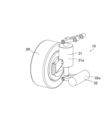
- 1 is a diagram showing a suspension device having a variable damper for performing a variable damper control method according to an embodiment of the present invention
- FIG. 2 is a block diagram showing a basic control block of a variable damper control method according to an embodiment of the present invention.
- FIG. 4 is a diagram showing a control law of a variable damper control method according to an embodiment of the present invention.
- 5 is a graph showing the relationship between wheel input load and travel distance in a simulation of a vehicle traveling on a rough road to which a variable damper control method according to an embodiment of the present invention is applied.
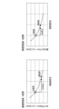
- 5 is a graph showing the results of a sensory evaluation by a driver of a vehicle to which a variable damper control method according to an embodiment of the present invention is applied.
- variable damper control method according to the present invention will be described with reference to the drawings. Note that the following embodiment does not limit the invention according to each claim, and not all of the combinations of features described in the embodiment are necessarily essential to the solution of the invention.
- FIG. 1 is a schematic diagram of a vehicle equipped with a variable damper that performs the variable damper control method according to an embodiment of the present invention
- FIG. 2 is a diagram showing a suspension device having a variable damper that performs the variable damper control method according to an embodiment of the present invention
- FIG. 3 is a block diagram showing the basic control blocks of the variable damper control method according to an embodiment of the present invention
- FIG. 4 is a diagram showing the control law of the variable damper control method according to an embodiment of the present invention
- FIG. 5 is a graph showing the relationship between wheel input load and travel distance simulating rough road driving of a vehicle to which the variable damper control method according to an embodiment of the present invention is applied
- FIG. 6 is a graph showing the results of a sensory evaluation by a driver of a vehicle to which the variable damper control method according to an embodiment of the present invention is applied.
- variable damper control method is executed by an electronic control unit 7 mounted on a vehicle 1.
- vehicle 1 has front wheels 2F arranged on the left and right sides of the front of the vehicle 1, and rear wheels 2R arranged on the left and right sides of the rear of the vehicle 1.
- the front wheels 2F and rear wheels 2R have friction brake devices 3 that brake the rotation of the wheels by frictional force.
- the front wheels 2F are driven by an on-board motor 4 mounted on the vehicle body, and the rear wheels 2R are driven by an in-wheel motor 5 housed within the rear wheels 2R.
- the front wheels 2F are also equipped with a steering mechanism (not shown) that tilts the front wheels 2F in the steering direction in response to the operation of a steering wheel 6 located in the driver's seat, and function as steered wheels.
- the steering mechanism can employ various conventionally known configurations, for example, a by-wire system with a steering actuator can be used.
- the steering actuator is wired so that it can receive signals from an electronic control unit 7, which receives signals from an operating unit 6a having a steering wheel 6 operated by the driver and performs predetermined processing, and controls the steering angle of the front wheels 2F to correspond to the steering wheel 6 operated by the driver.
- the electronic control unit 7 is also connected to the on-board motor 4 and the in-wheel motor 5, and when the driver operates the accelerator pedal 9a, it controls the on-board motor 4 and the in-wheel motor 5 to apply driving force in accordance with the amount of operation of the accelerator pedal 9a.
- the driver operates the brake pedal 9b, it controls the friction brake device 3 and the on-board motor 4 and the in-wheel motor 5 to operate as regenerative braking means in accordance with the brake operation.
- the friction brake device 3 has a disk-shaped brake disc 3a attached coaxially to the axles of the front wheels 2F and rear wheels 2R, and a caliper 3b equipped with brake pads that grip the brake disc 3a in the axial direction.
- the caliper 3b is connected to a master cylinder (not shown) that is activated when the driver operates the brake pedal 9b, and generates frictional force by being pressed against the brake disc 3a due to the amplification effect of hydraulic pressure and air pressure from the master cylinder.
- the friction brake device 3 can adjust the degree of pressing of the caliper 3b as necessary to adjust the frictional force between the brake pads and the brake disc 3a, regardless of the force applied to the brake pedal 9b by the driver, upon receiving a signal from the electronic control unit 7.
- the on-board motor 4 and the in-wheel motor 5 rotate in such a way that the vehicle 1 moves forward or backward in the direction of travel in response to a signal from the electronic control unit 7 in accordance with the opening degree of the accelerator pedal 9a operated by the driver.
- the brake pedal 9b is operated to brake
- the on-board motor 4 and the in-wheel motor 5 input shaft rotation in the opposite direction to operate as a generator, and are also used as regenerative braking devices that convert kinetic energy into electrical energy and recover or consume it to use for braking.
- the electronic control unit 7 has a microprocessor as a control means, and is powered by a battery (not shown).
- the electronic control unit 7 receives signals from the operation unit 6a, brake pedal 9b, accelerator pedal 9a, etc., processes the various signals, and transmits signals to drive the on-board motor 4 and in-wheel motor 5 at a predetermined rotation speed.
- the front wheels 2F and rear wheels 2R are attached to an active suspension device 10.
- the active suspension device 10 is attached between each wheel (e.g., rear wheel 2R) and the vehicle body, and absorbs vibrations and shocks input from the road surface, maintains the posture of the vehicle body, and ensures driving stability.
- the active suspension device 10 has an active suspension 31 and a variable damper 32.
- the active suspension 31 is equipped with a spring, which is a compression coil spring, and a vehicle height adjustment actuator 31a that suppresses the oscillating movement of the spring and can adjust the height of the vehicle body from the ground.
- a spring which is a compression coil spring
- a vehicle height adjustment actuator 31a that suppresses the oscillating movement of the spring and can adjust the height of the vehicle body from the ground.
- the vehicle height adjustment actuator 31a for example, has a ball screw mechanism in which a ball screw and a ball screw nut are screwed together, and generates a damping force from the resistance force of the motor that generates electricity by the vertical expansion and contraction movement of the ball screw mechanism.
- the damping force can be adjusted by the driving force of the ball screw mechanism, which expands and contracts up and down when electricity is applied to the motor.
- the overall length of the active suspension 31 can be expanded and contracted, and the height of the vehicle body from the ground can be adjusted by changing the distance between the wheels and the vehicle body.
- the variable damper 32 is a rotary damper that utilizes the damping force generated by magnetic viscosity resistance.
- the variable damper 32 is connected to the electronic control unit 7 and is equipped with a variable damper actuator 32a that can adjust the damping force by current control.
- variable damper actuator 32a is held by, for example, bearings so that the rotating shaft can rotate relative to the main body case.
- a coil and rotor are built into the main body case, and the rotating shaft is attached to the rotor. There is a gap around the rotor, which is filled with magnetic fluid.
- current is passed through the coil of such a variable damper actuator 32a, the viscous resistance of the magnetic fluid increases, generating a force that impedes the rotation of the rotor.
- the variable damper actuator 32a can adjust the damping force of the variable damper 32.
- variable damper 32 can generate a damping force electrically, resulting in excellent responsiveness and the ability to suppress vibrations of the vehicle body even when there are high-frequency bumps in the road surface while driving.
- the viscous resistance of the magnetic fluid can be adjusted steplessly, it is possible to control the current to a minimum in order to generate the required torque, thereby reducing power consumption.
- the active suspension device 10 is connected to the electronic control unit 7 and is configured to transmit the amount of expansion and contraction of the active suspension 31 and the damping force of the variable damper 32 to the electronic control unit 7.
- a vehicle height sensor 8 is also attached to the vehicle 1.
- the vehicle height sensor 8 is a sensor that can measure the distance from the underside of the vehicle 1 to the road surface, and for example, an optical sensor or an ultrasonic distance sensor is preferably used.
- the vehicle height data measured by the vehicle height sensor 8 is transmitted to the electronic control unit 7 and processed.
- control method of the variable damper 32 according to this embodiment controls the damping force of the variable damper 32 of the active suspension device 10 attached to the rear wheel 2R of the vehicle 1 described above.
- the electronic control unit 7 includes a tire load determination unit 21 that acquires the wheel rotation speeds of the front wheels 2F and rear wheels 2R and determines the loads on the front wheels 2F and rear wheels 2R, a suspension stroke speed determination unit 22 that acquires the suspension stroke of the active suspension 31 and determines the suspension stroke speed, a target damping force calculation unit 23 that calculates a target damping force from the tire load and suspension stroke speed obtained from the tire load determination unit 21 and the suspension stroke speed determination unit 22, and a damping force control device 24 that controls the variable damper 32 to achieve the calculated target damping force.
- a tire load determination unit 21 that acquires the wheel rotation speeds of the front wheels 2F and rear wheels 2R and determines the loads on the front wheels 2F and rear wheels 2R
- a suspension stroke speed determination unit 22 that acquires the suspension stroke of the active suspension 31 and determines the suspension stroke speed
- a target damping force calculation unit 23 that calculates a target damping force from the tire load and suspension stroke speed obtained from the tire load determination unit 21 and the suspension stroke speed
- the damping force control device 24 may be in operation all the time, but it is preferable to set it to operate, for example, when it is determined that the vehicle 1 is traveling on a rough road with large bumps.
- the determination of whether or not the vehicle 1 is traveling on a rough road may be made by setting it to operate when the vehicle height data obtained by the vehicle height sensor 8 exceeds a predetermined fluctuation range, or by performing image processing on image data of the road surface obtained by an on-board camera (not shown) to determine whether or not the vehicle 1 is traveling on a rough road.
- the target damping force calculation unit 23 compares the wheel speeds of the front wheels 2F and rear wheels 2R based on the tire load determined by the tire load determination unit 21.
- the stroke direction can be known from the suspension stroke speed determined by the suspension stroke speed determination unit 22, and therefore it is possible to determine whether the variable damper 32 is in an extended or contracted state.
- the target damping force calculation unit 23 calculates the target damping force of the variable damper 32 based on the control law shown in FIG. 4 according to the wheel speed and the state of the variable damper.
- the rear wheel 2R when the wheel speed of the rear wheel 2R is lower than the wheel speed of the front wheel 2F and the variable damper 32 is in an extended state, the rear wheel 2R is pressed against the road surface while traveling on a rough road. At this time, the rear wheel 2R is in an overloaded state and the tire contact with the ground is deteriorated, so the target damping force is maximized so that the damping force becomes large in order to suppress the extension of the variable damper 32.
- variable damper 32 transitions to a compressed state
- the rear wheel 2R is lifted off the road surface while traveling on a rough road, and the overload on the rear wheel 2R is improved.
- the target damping force is minimized so that the damping force is reduced in order to promote the compression of the variable damper 32.
- the rear wheel 2R will be lifted off the road surface while traveling on a rough road.
- the rear wheel 2R is in an insufficient load state, and the tire contact with the ground is deteriorated.
- the target damping force is maximized so that the damping force becomes large in order to suppress the compression of the variable damper 32.
- the rear wheel 2R which is traveling on a rough road, is about to come into contact with the road surface, and the load deficiency of the rear wheel 2R is improved. At this time, the target damping force is minimized so that the damping force is reduced in order to promote the extension of the variable damper 32.
- the in-wheel motor 5 is provided and the damping force of the variable damper 32 of the rear wheels 2R is controlled so that the wheel speed of the rear wheels 2R, which have a large unsprung weight, matches the wheel speed of the front wheels 2F, which have a light unsprung weight.
- This improves the road surface following ability of the rear wheels 2R when traveling on rough roads, suppressing slippage and improving tire contact with the ground, and suppressing unsprung and over-sprung vibrations.
- variable damper control method As shown in FIG. 5, it can be seen that the example in which the variable damper control method according to this embodiment is applied has a reduced wheel input load compared to the comparative example in which a vehicle having a conventional damper is simulated.
- the reduced wheel input load indicates that unsprung vibration is suppressed.
- the amplitude of the tire input load is reduced, which confirms that tire ground contact is improved.
- a sensory test was conducted to compare a vehicle to which the variable damper control method according to the present embodiment was applied with a conventional vehicle, to ascertain how the driver felt the vehicle vibrations.
- the sensory test was conducted by quantifying and evaluating how the driver felt the vehicle vibrations while driving the vehicle over a set driving section.
- the sensory test evaluated the degree to which the driver felt continuous large vibrations and the degree to which the driver felt impact when the driver felt large vibrations, using numerical values.
- the road surface used in the sensory test was a rough road similar to the Belgian road used in the simulation in Figure 5, and the vehicle was actually driven over it.
- the vibration sensation was evaluated in the A section, and the impact sensation was evaluated in the B section.
- the average value of the wheel input load in the A section in Figure 5 was plotted on the vertical axis, and the degree to which the driver felt it was plotted on the horizontal axis.
- the maximum value of the wheel input load in the B section in Figure 5 was plotted on the vertical axis, and the degree to which the driver felt it was plotted on the horizontal axis, similar to the vibration sensation.
- the sensory evaluation of the vibration sensation of the Example is improved by 0.6 points compared to the Comparative Example, and the evaluation of the impact sensation is improved by 0.2 points.
- the vibration sensation and impact sensation scores are improved to an average of 2.4 points compared to a conventional vehicle, with 2.6 points in the vibration sensation area and 2.2 points in the impact sensation area, and the sensory test results also confirmed that vehicle vibration is less noticeable than before.
- variable damper control method can improve the tire contact with the ground of the rear wheel 2R equipped with the in-wheel motor 5 and reduce unsprung vibration, making it possible to provide a vehicle with excellent road surface tracking when traveling on rough roads.
- the vehicle that performs the variable damper control method according to this embodiment is equipped with the active suspension device 10 as described above, it is possible to obtain vehicle posture information from the stroke amount obtained from each active suspension device 10 attached to each wheel and a horizontal sensor attached to the vehicle, and it is also possible to correct the damping force appropriately according to the posture.
- the wheel speed is controlled by comparing the wheel speeds of the front and rear wheels, but the damping force may be controlled based on the magnitude relationship between the rear wheels equipped with in-wheel motors 5 and the vehicle speed.
- the variable damper control method according to this embodiment is applied to a vehicle 1 in which the front wheels 2F are driven by an on-board motor 4, but it may also be applied to a vehicle in which the front wheels 2F are also driven by in-wheel motors 5 and the rear wheels are driven by an on-board motor 4. It is clear from the claims that such modified or improved forms are also included within the technical scope of the present invention.
Landscapes
- Engineering & Computer Science (AREA)
- Mechanical Engineering (AREA)
- Automation & Control Theory (AREA)
- Vehicle Body Suspensions (AREA)
Abstract
Description
Claims (6)
- 前輪又は後輪の何れか一方の車輪が当該車輪に収納されたインホイールモータによって駆動され、何れか他方が車体に備えたオンボードモータで駆動され、少なくとも前記インホイールモータによって駆動される車輪が減衰力を調整可能な可変ダンパを有するサスペンション装置に取り付けられる車両の可変ダンパの制御方法であって、
前記可変ダンパは、前記インホイールモータによって駆動される車輪の車輪速に応じて減衰力を調整することを特徴とする可変ダンパの制御方法。 - 請求項1に記載の可変ダンパの制御方法において、
前記可変ダンパは、前記インホイールモータによって駆動される車輪の車輪速と、前記オンボードモータで駆動される車輪の車輪速とを比較して前記減衰力を調整することを特徴とする可変ダンパの制御方法。 - 請求項1に記載の可変ダンパの制御方法において、
前記可変ダンパは、前記インホイールモータによって駆動される車輪の車輪速と、前記車両の車速とを比較して前記減衰力を調整することを特徴とする可変ダンパの制御方法。 - 請求項1又は2に記載の可変ダンパの制御方法において、
前記車両は、前輪がオンボードモータによって駆動され、後輪が前記インホイールモータによって駆動されることを特徴とする可変ダンパの制御方法。 - 請求項1に記載の車両の制御方法において、
前記可変ダンパは、前記車両の姿勢情報に基づいて減衰力を補正することを特徴とする可変ダンパの制御方法。 - 請求項1に記載の可変ダンパの制御方法において、
前記可変ダンパは、前記サスペンション装置の抵抗力を一定に保つように前記減衰力を調整することを特徴とする可変ダンパの制御方法。
Priority Applications (2)
| Application Number | Priority Date | Filing Date | Title |
|---|---|---|---|
| CN202480032194.5A CN121100071A (zh) | 2023-06-09 | 2024-05-20 | 可变阻尼器的控制方法 |
| EP24819134.8A EP4725723A1 (en) | 2023-06-09 | 2024-05-20 | Method for controlling variable damper |
Applications Claiming Priority (2)
| Application Number | Priority Date | Filing Date | Title |
|---|---|---|---|
| JP2023-095696 | 2023-06-09 | ||
| JP2023095696A JP2024176858A (ja) | 2023-06-09 | 2023-06-09 | 可変ダンパの制御方法 |
Publications (1)
| Publication Number | Publication Date |
|---|---|
| WO2024252901A1 true WO2024252901A1 (ja) | 2024-12-12 |
Family
ID=93795380
Family Applications (1)
| Application Number | Title | Priority Date | Filing Date |
|---|---|---|---|
| PCT/JP2024/018429 Ceased WO2024252901A1 (ja) | 2023-06-09 | 2024-05-20 | 可変ダンパの制御方法 |
Country Status (4)
| Country | Link |
|---|---|
| EP (1) | EP4725723A1 (ja) |
| JP (1) | JP2024176858A (ja) |
| CN (1) | CN121100071A (ja) |
| WO (1) | WO2024252901A1 (ja) |
Citations (7)
| Publication number | Priority date | Publication date | Assignee | Title |
|---|---|---|---|---|
| JPH06336109A (ja) | 1993-05-27 | 1994-12-06 | Suzuki Motor Corp | 車両用サスペンション制御装置 |
| JPH0781352A (ja) * | 1993-09-13 | 1995-03-28 | Suzuki Motor Corp | 車両用サスペンション制御装置 |
| JP2008207739A (ja) * | 2007-02-27 | 2008-09-11 | Honda Motor Co Ltd | 電動車両 |
| JP2009040174A (ja) * | 2007-08-08 | 2009-02-26 | Nippon Soken Inc | ハイブリッド車両 |
| JP2009279984A (ja) * | 2008-05-20 | 2009-12-03 | Toyota Motor Corp | 車両用サスペンションシステム |
| JP2011093415A (ja) * | 2009-10-29 | 2011-05-12 | Equos Research Co Ltd | 車両用キャンバ角制御装置 |
| JP2019199149A (ja) * | 2018-05-16 | 2019-11-21 | トヨタ自動車株式会社 | 減衰力制御装置 |
-
2023
- 2023-06-09 JP JP2023095696A patent/JP2024176858A/ja active Pending
-
2024
- 2024-05-20 CN CN202480032194.5A patent/CN121100071A/zh active Pending
- 2024-05-20 EP EP24819134.8A patent/EP4725723A1/en active Pending
- 2024-05-20 WO PCT/JP2024/018429 patent/WO2024252901A1/ja not_active Ceased
Patent Citations (7)
| Publication number | Priority date | Publication date | Assignee | Title |
|---|---|---|---|---|
| JPH06336109A (ja) | 1993-05-27 | 1994-12-06 | Suzuki Motor Corp | 車両用サスペンション制御装置 |
| JPH0781352A (ja) * | 1993-09-13 | 1995-03-28 | Suzuki Motor Corp | 車両用サスペンション制御装置 |
| JP2008207739A (ja) * | 2007-02-27 | 2008-09-11 | Honda Motor Co Ltd | 電動車両 |
| JP2009040174A (ja) * | 2007-08-08 | 2009-02-26 | Nippon Soken Inc | ハイブリッド車両 |
| JP2009279984A (ja) * | 2008-05-20 | 2009-12-03 | Toyota Motor Corp | 車両用サスペンションシステム |
| JP2011093415A (ja) * | 2009-10-29 | 2011-05-12 | Equos Research Co Ltd | 車両用キャンバ角制御装置 |
| JP2019199149A (ja) * | 2018-05-16 | 2019-11-21 | トヨタ自動車株式会社 | 減衰力制御装置 |
Also Published As
| Publication number | Publication date |
|---|---|
| EP4725723A1 (en) | 2026-04-15 |
| JP2024176858A (ja) | 2024-12-19 |
| CN121100071A (zh) | 2025-12-09 |
Similar Documents
| Publication | Publication Date | Title |
|---|---|---|
| US7788011B2 (en) | Braking and drive force control apparatus for a vehicle | |
| CN111137096B (zh) | 用于可变阻尼力阻尼器的控制系统 | |
| CN112848832B (zh) | 车辆集成控制方法和车辆集成控制系统 | |
| CN103153728B (zh) | 车辆制动/驱动力控制系统和车辆制动/驱动力控制方法 | |
| US9233689B2 (en) | Vehicle braking/driving force control apparatus | |
| US9227637B2 (en) | Vehicle braking/driving force control apparatus | |
| WO2012066612A1 (ja) | 車両制御装置 | |
| JP2011529822A (ja) | オートバイ用セミアクティブサスペンションシステムを制御する方法および装置 | |
| US11912089B1 (en) | Method and apparatus to dynamically increase tire traction in a vehicle by generating positive forces between a wheel and a body of the vehicle and then quickly removing such forces | |
| CN115257273A (zh) | 一种悬架系统的控制方法、装置及悬架系统 | |
| WO2011070634A1 (ja) | 車両制御装置 | |
| JP2009173089A (ja) | 車両の制御装置 | |
| US20170028983A1 (en) | Electric vehicle | |
| JP5144289B2 (ja) | 減衰力可変ダンパの制御装置 | |
| CN109996689A (zh) | 用于控制车辆的轮轴悬架的方法 | |
| JP2024176858A (ja) | 可変ダンパの制御方法 | |
| US9139063B2 (en) | Vehicle suspension device | |
| WO2024247547A1 (ja) | 車両の制御方法 | |
| JP4797586B2 (ja) | 車輌の制駆動力制御装置 | |
| JP4577149B2 (ja) | 車両の制御装置 | |
| JPH07205628A (ja) | サスペンション制御装置 | |
| EP4204283B1 (en) | A system and a method for counteracting cabin vibrations | |
| JP2020185957A (ja) | 弾性体ブッシュ、サスペンション装置、及び、動力伝達機構の支持構造 | |
| JP2008544926A (ja) | 車両のローリング防止方法およびシステムならびに対応する車両 | |
| KR101297961B1 (ko) | 차량용 능동제어 후륜 현가장치의 토우제어장치와 그제어방법 |
Legal Events
| Date | Code | Title | Description |
|---|---|---|---|
| 121 | Ep: the epo has been informed by wipo that ep was designated in this application |
Ref document number: 24819134 Country of ref document: EP Kind code of ref document: A1 |
|
| WWE | Wipo information: entry into national phase |
Ref document number: 2024819134 Country of ref document: EP |
|
| NENP | Non-entry into the national phase |
Ref country code: DE |
|
| ENP | Entry into the national phase |
Ref document number: 2024819134 Country of ref document: EP Effective date: 20260109 |
|
| ENP | Entry into the national phase |
Ref document number: 2024819134 Country of ref document: EP Effective date: 20260109 |
|
| ENP | Entry into the national phase |
Ref document number: 2024819134 Country of ref document: EP Effective date: 20260109 |
|
| ENP | Entry into the national phase |
Ref document number: 2024819134 Country of ref document: EP Effective date: 20260109 |
|
| ENP | Entry into the national phase |
Ref document number: 2024819134 Country of ref document: EP Effective date: 20260109 |
|
| WWP | Wipo information: published in national office |
Ref document number: 2024819134 Country of ref document: EP |