WO2024252877A1 - 積層フィルムおよび画像表示装置 - Google Patents
積層フィルムおよび画像表示装置 Download PDFInfo
- Publication number
- WO2024252877A1 WO2024252877A1 PCT/JP2024/018020 JP2024018020W WO2024252877A1 WO 2024252877 A1 WO2024252877 A1 WO 2024252877A1 JP 2024018020 W JP2024018020 W JP 2024018020W WO 2024252877 A1 WO2024252877 A1 WO 2024252877A1
- Authority
- WO
- WIPO (PCT)
- Prior art keywords
- refractive index
- index layer
- layer
- low refractive
- laminated film
- Prior art date
- Legal status (The legal status is an assumption and is not a legal conclusion. Google has not performed a legal analysis and makes no representation as to the accuracy of the status listed.)
- Ceased
Links
Images

Classifications
-
- G—PHYSICS
- G02—OPTICS
- G02B—OPTICAL ELEMENTS, SYSTEMS OR APPARATUS
- G02B3/00—Simple or compound lenses
-
- G—PHYSICS
- G02—OPTICS
- G02B—OPTICAL ELEMENTS, SYSTEMS OR APPARATUS
- G02B3/00—Simple or compound lenses
- G02B3/02—Simple or compound lenses with non-spherical faces
- G02B3/06—Simple or compound lenses with non-spherical faces with cylindrical or toric faces
-
- G—PHYSICS
- G02—OPTICS
- G02B—OPTICAL ELEMENTS, SYSTEMS OR APPARATUS
- G02B5/00—Optical elements other than lenses
-
- G—PHYSICS
- G02—OPTICS
- G02B—OPTICAL ELEMENTS, SYSTEMS OR APPARATUS
- G02B5/00—Optical elements other than lenses
- G02B5/04—Prisms
-
- G—PHYSICS
- G02—OPTICS
- G02B—OPTICAL ELEMENTS, SYSTEMS OR APPARATUS
- G02B5/00—Optical elements other than lenses
- G02B5/08—Mirrors
-
- G—PHYSICS
- G03—PHOTOGRAPHY; CINEMATOGRAPHY; ANALOGOUS TECHNIQUES USING WAVES OTHER THAN OPTICAL WAVES; ELECTROGRAPHY; HOLOGRAPHY
- G03H—HOLOGRAPHIC PROCESSES OR APPARATUS
- G03H1/00—Holographic processes or apparatus using light, infrared or ultraviolet waves for obtaining holograms or for obtaining an image from them; Details peculiar thereto
- G03H1/02—Details of features involved during the holographic process; Replication of holograms without interference recording
-
- G—PHYSICS
- G09—EDUCATION; CRYPTOGRAPHY; DISPLAY; ADVERTISING; SEALS
- G09F—DISPLAYING; ADVERTISING; SIGNS; LABELS OR NAME-PLATES; SEALS
- G09F19/00—Advertising or display means not otherwise provided for
- G09F19/12—Advertising or display means not otherwise provided for using special optical effects
Definitions
- the present invention relates to a laminated film and an image display device.
- Decorative films are used as a means of improving the design of various products.
- a technique has been proposed in which a decorative film is attached to a cover case that houses a smartphone, tablet terminal, etc., and/or a glass panel that constitutes the back surface (the surface not involved in image display) of an image display device, thereby imparting design to the image display device itself.
- a decorative film having a concave-convex layer and a low refractive index layer is known.
- problems may arise such as insufficient brightness of the applied design and/or uneven coloring of the applied design. Therefore, a decorative film that can further increase the commercial value of image display devices is desired.
- the present invention was made to solve the above-mentioned problems in the past, and its main objective is to provide a laminated film that can realize a design with high brightness and reduced color unevenness.
- a laminate film according to an embodiment of the present invention has a decorative layer having a first main surface and a second main surface, the first main surface having a concave-convex structure; a low refractive index layer provided on the first main surface of the decorative layer; and a high refractive index layer provided on the side of the low refractive index layer opposite the decorative layer.
- the low refractive index layer has a refractive index of 1.30 or less and a thickness of 0.3 ⁇ m or more.
- the high refractive index layer has a refractive index of 1.60 to 2.20 and a thickness of 0.3 ⁇ m or more.
- the decorative layer has a function of changing the direction of light.
- P/H is 1.5 or more.
- the laminate film further has a colored layer on the opposite side of the high refractive index layer to the low refractive index layer.
- a laminated film can be provided that can realize a design with high brightness and reduced color unevenness.
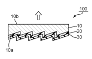
- FIG. 1 is a schematic cross-sectional view of a laminated film according to one embodiment of the present invention.
- FIG. 2 is a schematic cross-sectional view of a laminated film according to another embodiment of the present invention.
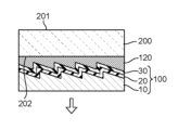
- FIG. 2 is a schematic cross-sectional view illustrating a usage form of the laminated film of FIG. 1.
- FIG. 1 is a schematic cross-sectional view of a laminated film according to one embodiment of the present invention.
- the laminated film 100 of the illustrated example has a decorative layer 10, a low refractive index layer 20, and a high refractive index layer 30.
- the decorative layer 10 has a first main surface 10a and a second main surface 10b, and the first main surface 10a has an uneven structure.
- the low refractive index layer 20 is provided on the first main surface 10a of the decorative layer 10.
- the high refractive index layer 30 is provided on the opposite side of the decorative layer 10 from the low refractive index layer 20.
- the low refractive index layer 20 and the high refractive index layer 30 in combination in such a positional relationship with respect to the decorative layer 10, a laminated film that can realize a design with high brightness and suppressed color unevenness can be obtained.
- the low refractive index layer 20 and the high refractive index layer 30 typically follow the uneven structure of the decorative layer 10 as shown in the illustrated example due to the relationship between their thickness and the height (depth) of the uneven structure.
- either the low refractive index layer 20 or the high refractive index layer 30 may fill the recesses of the uneven structure, making the side opposite the decorative layer a flat surface.
- the decorative layer 10 typically has a function of changing the direction of light.
- the decorative layer 10 can express a design according to the purpose by controlling the uneven structure, for example, by controlling the transmission, reflection, diffraction, scattering, and diffusion of light in combination.
- a laminated film including such a decorative layer can achieve the following effects depending on the type of decorative layer: (1) it can decorate the surface of various products and improve their design; (2) it can change the color of the surface of various products depending on the viewing angle; and (3) it can display different images, characters, etc. on the surface of various products depending on the viewing angle. Therefore, the laminated film according to the embodiment of the present invention can also be called a decorative film, an optical laminate, etc.
- the decorative layer 10 can express a design on one or both of the first main surface side and the second main surface side depending on the specific configuration.
- the decorative layer 10 can preferably express a design at least on the arrow side in FIG. 1.
- any appropriate configuration can be adopted as long as it has the above-mentioned functions.
- the specific structure of the decorative layer will be explained in Section B below.
- the low refractive index layer 20 typically has a refractive index of 1.30 or less. By providing such a low refractive index layer at a predetermined position, appropriate reflection can be achieved at the interface with the decorative layer. As a result, the reflectance of the laminated film can be increased, and therefore a design with high brightness can be expressed.
- the low refractive index layer 20 may be formed on the first main surface 10a of the decorative layer 10 via an adhesive layer, or may be formed directly on the first main surface. Preferably, the low refractive index layer is formed directly on the first main surface. With this configuration, adverse effects caused by the refractive index of the adhesive layer can be avoided. Such direct formation can be achieved, for example, by coating or printing a low refractive index layer forming liquid as described below.
- the thickness of the low refractive index layer 20 is preferably 0.3 ⁇ m or more. If the thickness of the low refractive index layer is in this range, the effect of the embodiment of the present invention can be more remarkable. Specifically, the hue change of the laminated film can be suppressed, and as a result, color unevenness of the expressed design can be suppressed. This can be presumed to be because thin film interference between the low refractive index layer and the high refractive index layer is suppressed.
- the specific configuration of the low refractive index layer will be described in Section C below.
- the adhesive layer may be composed of a pressure-sensitive adhesive or an adhesive.
- the adhesive layer (or the adhesive or pressure-sensitive adhesive that constitutes it) may have a configuration that is well known in the industry, so a detailed description will be omitted. Unless otherwise specified below, the same applies to other "adhesive layers.”
- the high refractive index layer 30 typically has a refractive index of 1.60 to 2.20. By providing such a high refractive index layer at a predetermined position, a synergistic effect with the effect of providing a low refractive index layer can be achieved, resulting in an even better reflection in the laminated film. As a result, a design with higher brightness than when a low refractive index layer is provided alone can be expressed.
- the high refractive index layer 30 may be formed on the low refractive index layer 20 via an adhesive layer, or may be formed directly on the low refractive index layer 20. Preferably, the high refractive index layer is formed directly on the low refractive index layer. With this configuration, adverse effects caused by the refractive index of the adhesive layer can be avoided.
- Such direct formation can be achieved, for example, by coating or printing a high refractive index layer forming liquid as described below.
- the thickness of the high refractive index layer 30 is preferably 0.3 ⁇ m or more. If the thickness of the high refractive index layer is in this range, the effects of the embodiment of the present invention can be more pronounced, as in the case where the thickness of the low refractive index layer is set to a predetermined value or more. Specifically, the hue change of the laminated film can be suppressed, and as a result, color unevenness of the displayed design can be suppressed.
- the thickness of the high refractive index layer is greater than the thickness of the low refractive index layer.
- the difference between the thickness of the high refractive index layer and the thickness of the low refractive index layer may be, for example, 0.2 ⁇ m to 3.0 ⁇ m, or may be, for example, 1.0 ⁇ m to 2.0 ⁇ m.
- the specific configuration of the high refractive index layer will be described in Section D below.
- FIG. 2 is a schematic cross-sectional view of a laminated film according to another embodiment of the present invention.
- the laminated film 101 in the illustrated example further has a colored layer 40 on the side of the high refractive index layer 30 opposite the low refractive index layer 20.
- the colored layer 40 may be formed on the high refractive index layer 30 via an adhesive layer, or may be formed directly on the high refractive index layer 30.
- the colored layer 40 is formed on the high refractive index layer 30 via an adhesive layer 50.
- the adhesive layer in this embodiment may typically be a pressure-sensitive adhesive layer. The specific configuration of the colored layer will be described in Section E below.
- an adhesive layer (not shown) may be provided as the outermost layer on the high refractive index layer 30 side.
- the laminate film can be attached to an image display device.
- a release liner (not shown) is temporarily attached until the laminate film is used. By temporarily attaching the release liner, the adhesive layer is protected and the laminate film can be formed into a roll.
- the decorative layer 10 has a function of changing the direction of light, as described above.
- Specific examples of the decorative layer include a shaping film, a reflective hologram film, a microlens array film, a prism film, and a lenticular lens.
- a reflective hologram film and the like may also be included in the shaping film, but in this specification, for convenience, the shaping film and the reflective hologram film are both described.
- any suitable configuration may be adopted for the shaped film depending on the purpose.
- the uneven structure of the shaped film include a structure in which rectangular parallelepiped unevenness is arranged in a checkerboard pattern in a plan view, a structure in which the recesses have inclined surfaces at different angles as shown in FIG.
- a structure in which the recesses are in the shape of a quadrangular pyramid a structure in which the recesses are in the shape of a truncated quadrangular pyramid, a structure in which the recesses are in the shape of a dome, an uneven shape having convex portions at regular intervals with a rectangular cross section and extending in one direction (striped in a plan view, so-called line and space), an uneven shape having convex portions at regular intervals with a corrugated cross section and extending in one direction, an uneven shape having convex portions at regular intervals with a triangular cross section and extending in one direction, and combinations thereof.
- the shaped film may be produced by any suitable method.
- the shaped film may be produced by transferring the relief structure of a mold to a soft resin sheet.
- soft resin sheets include semi-cured thermosetting or active energy ray curable resin sheets and thermoplastic resin sheets softened by heating. After the relief structure is transferred to the thermosetting or active energy ray curable resin sheet, the sheet is cured by heating or exposure to active energy rays (typically visible light or ultraviolet light) to fix the relief structure. After the relief structure is transferred to the thermoplastic resin sheet, the sheet is solidified by cooling to fix the relief structure.
- any appropriate configuration may be adopted as the reflective hologram film depending on the purpose.
- Any appropriate fine uneven shape capable of exhibiting functions such as light diffusion, light scattering, light reflection, and light diffraction may be adopted as the uneven shape of the reflective hologram film.
- Representative examples include a Fourier transform structure, a lenticular lens, a light diffraction pattern, and a moth-eye structure.
- uneven shapes such as a hairline pattern, a matte pattern, a line pattern, and an interference pattern that do not have a light diffraction function but can exhibit a unique brilliance may also be used.
- the reflective hologram film can convert reflected light into diffracted light.
- a microlens array film typically has a flat base portion and a lens portion provided on one surface of the base portion.
- the lens portion is composed of a plurality of lenses.
- the lenses that make up the lens portion are typically convex lenses, and may have a dome shape, for example.
- the lenses may be arranged in a matrix, in a predetermined pattern (for example, stripes), or randomly.
- a prism film typically has a flat base portion and a prism portion.
- the prism portion typically consists of an array of multiple unit prisms that extend in one direction and have a triangular cross-section that is convex on the side opposite the base portion.
- the direction in which the unit prisms extend (the ridge direction of the unit prisms) can be set appropriately depending on the purpose.
- a lenticular lens typically has multiple convex cylindrical lenses with semicircular cross sections arranged in parallel (i.e., in a stripe pattern).
- P/H is preferably 1.5 or more, more preferably 2.0 or more, even more preferably 3.0 or more, and particularly preferably 5.0 or more.
- P/H is preferably 100 or less, more preferably 70 or less, even more preferably 60 or less, and particularly preferably 50 or less. If the P/H of the uneven structure of the decorative layer is in such a range, the effect of the embodiment of the present invention can be more remarkable. If P/H is too small, the low refractive index layer may not be properly formed. The upper limit of P/H can be determined according to the desired design.
- the "height of the unevenness” means the distance from the peak (or top) to the valley (or flat end) in one uneven portion, and when the unevenness is an irregular structure, it means the average distance from the peak (or top) to the valley (or flat end) in each uneven portion.
- pitches of unevenness refers to the distance from adjacent peaks (or apexes) to adjacent peaks (or apexes), and when the unevenness has an irregular structure, refers to the average distance from adjacent peaks (or apexes) to adjacent peaks (or apexes).
- the pitch P of the irregularities and the height H of the irregularities can each be set appropriately as long as the desired P/H is obtained.
- the pitch P is preferably 10 ⁇ m to 500 ⁇ m, more preferably 30 ⁇ m to 200 ⁇ m, and even more preferably 50 ⁇ m to 100 ⁇ m.
- the height H is preferably 0.1 ⁇ m to 100 ⁇ m, more preferably 1 ⁇ m to 50 ⁇ m, and even more preferably 2 ⁇ m to 20 ⁇ m.
- the thickness of the decorative layer (the maximum thickness corresponding to the convex portion) is preferably 50 ⁇ m to 3 mm (3000 ⁇ m), and more preferably 100 ⁇ m to 1 mm (1000 ⁇ m).
- the refractive index of the low refractive index layer 20 is typically 1.30 or less as described above, with the lower limit being greater than 1.00.
- the refractive index of the low refractive index layer 20 is preferably 1.13 to 1.28, more preferably 1.14 to 1.27, even more preferably 1.15 to 1.26, and particularly preferably 1.16 to 1.25. If the refractive index of the low refractive index layer is in such a range, the deterioration of the function of the decorative layer due to the provision of a layer on the first main surface (uneven surface) side of the decorative layer can be extremely well suppressed.
- the refractive index refers to the refractive index measured at a wavelength of 550 nm, unless otherwise specified.
- the refractive index is, for example, a value measured by the method described in the Examples below.
- the total light transmittance of the low refractive index layer 20 is preferably 85% to 99%, more preferably 87% to 98%, and even more preferably 89% to 97%.
- the haze of the low refractive index layer 20 is preferably less than 5%, more preferably less than 3%.
- the haze may be, for example, 0.1% or more, and may be 0.2% or more.
- the thickness of the low refractive index layer 20 is preferably 0.3 ⁇ m or more, more preferably 1.0 ⁇ m or more, even more preferably 1.2 ⁇ m or more, particularly preferably 1.5 ⁇ m or more, and particularly preferably 1.8 ⁇ m or more.
- the thickness of the low refractive index layer may be, for example, 2.2 ⁇ m or more, or may be, for example, 2.5 ⁇ m or more, or may be, for example, 2.8 ⁇ m or more.
- the thickness of the low refractive index layer may be, for example, 20 ⁇ m or less, or may be, for example, 10 ⁇ m or less, or may be, for example, 8 ⁇ m or less, or may be, for example, 5 ⁇ m or less. If the thickness of the low refractive index layer is in such a range, as described above, the hue change of the laminated film can be suppressed, and as a result, the color unevenness of the resulting design can be suppressed.
- the low refractive index layer may have any suitable structure that can achieve the desired characteristics.
- Materials for the low refractive index layer include, for example, materials described in International Publication No. 2004/113966, JP 2013-254183 A, and JP 2012-189802 A.
- Representative examples of materials for the low refractive index layer include silicon compounds. Examples of silicon compounds include silica-based compounds; hydrolyzable silanes and their partial hydrolyzates and dehydration condensates; silicon compounds containing silanol groups; and activated silica obtained by contacting silicate with acid or ion exchange resin.
- materials for the low refractive index layer include organic polymers; polymerizable monomers (e.g., (meth)acrylic monomers and styrene monomers); and curable resins (e.g., (meth)acrylic resins, fluorine-containing resins, and urethane resins). These materials may be used alone or in combination of two or more.
- the low refractive index layer may contain spaces such as holes and gaps therein.
- the porosity of the low refractive index layer is preferably 20 volume % to 60 volume %, more preferably 25 volume % to 55 volume %, even more preferably 30 volume % to 50 volume %, and particularly preferably 35 volume % to 45 volume %.
- the refractive index of the low refractive index layer can be set in an appropriate range and strength can be ensured.
- the porosity is a value calculated from the refractive index measured by an ellipsometer using the Lorentz-Lorenz's formula.
- the size of the voids that can be contained in the low refractive index layer can be adjusted to a desired size depending on the purpose and application.
- the size of the voids that can be contained in the low refractive index layer is, for example, 2 nm or more, preferably 5 nm or more, more preferably 10 nm or more, and even more preferably 20 nm or more.
- the size of the voids that can be contained in the low refractive index layer is, for example, 500 nm or less, preferably 200 nm or less, and more preferably 100 nm or less.
- the size of the voids refers to the diameter of the long axis of the voids, out of the diameter of the long axis and the diameter of the short axis.
- the pore size can be quantified by the BET test method.
- a measurement sample e.g., the formed low refractive index layer
- a specific surface area measurement device e.g., "ASAP2020” manufactured by Micromeritics
- the measurement sample is dried under reduced pressure at room temperature for 24 hours to degas the gas contained in the measurement sample.
- an adsorption isotherm is drawn by adsorbing nitrogen gas onto the measurement sample, and the pore distribution is determined. This makes it possible to evaluate the pore size.
- the low refractive index layer having a space therein examples include a porous layer composed of a porous body and/or a layer containing an air layer at least in a part thereof.
- the low refractive index layer typically contains aerogel and/or particles (which may be hollow fine particles and/or porous particles, for example).
- the low refractive index layer may preferably be a nanoporous layer (specifically, a porous layer in which 90% or more of the pores have a diameter in the range of 10-1 nm to 103 nm).
- the particle is typically made of a silica-based compound.
- particle shapes include spherical, plate-like, needle-like, string-like, and bunch-of-grapes shapes.
- string-like particles include particles in which multiple particles having spherical, plate-like, or needle-like shapes are strung together like beads, short fiber-like particles (such as the short fiber-like particles described in JP-A-2001-188104), and combinations of these.
- the string-like particles may be linear or branched.
- bunch-of-grapes-shaped particles include particles in which multiple spherical, plate-like, and needle-like particles are aggregated to form a bunch-of-grapes shape. The shape of the particles can be confirmed, for example, by observation with a transmission electron microscope.
- An example of a low refractive index layer is a structure composed of one or more types of constituent units that form a fine void structure, and in which these constituent units are bonded together (for example, chemically bonded via catalytic action).
- the shape of the constituent units can be, for example, particulate, fibrous, rod-like, or flat.
- the constituent units may have only one shape, or a combination of two or more shapes.
- a specific example of the low refractive index layer is a porous layer made of a porous body in which particles having micropores (hereinafter referred to as micropore particles) are chemically bonded to each other.
- a porous layer can be obtained, for example, by chemically bonding micropore particles to each other.
- the shape of the micropore particles is not particularly limited, and may be, for example, spherical or other shapes.
- the micropore particles may be, for example, sol-gel beaded particles, nanoparticles (for example, hollow nanosilica nanoballoon particles), nanofibers, etc.
- the micropore particles typically include inorganic substances.
- the micropore particles are, for example, micropore particles of a silicon compound, and the porous body is, for example, a silicone porous body.
- the micropore particles of a silicon compound include, for example, a pulverized gel silica compound.
- a low refractive index layer is a layer that contains a fibrous material such as nanofibers, and in which spaces are formed by the entanglement of the fibrous material.
- Further examples of low refractive index layers include layers formed using hollow nanoparticles or nanoclay, and layers formed using hollow nanoballoons or magnesium fluoride.
- the low refractive index layer may be composed of a single constituent material, or may be composed of multiple constituent materials.
- the low refractive index layer may be composed of a single form of the above examples, or may be composed of multiple forms of the above examples.
- the porous layer may be, for example, an open-cell structure in which the pore structure is continuous.
- the open-cell structure means that the pore structure is three-dimensionally connected in a porous body (for example, a silicone porous body), and can also be said to be a state in which the spaces of the pore structure are continuous.
- the open-cell structure of the porous layer can increase the porosity. It is difficult to form an open-cell structure using closed-cell particles having individual pore structures, such as hollow particles (for example, hollow silica).
- the silica sol particles can have a three-dimensional dendritic structure, so that the dendritic particles can settle and accumulate in the coating film (coated film of a sol containing a pulverized gel-like silicon compound) to easily form an open-cell structure.
- the porous layer has a monolith structure in which the open-cell structure includes a plurality of pore distributions.
- the monolith structure means, for example, a hierarchical structure including a structure in which nano-sized fine pores exist and an open-cell structure in which nano-sized fine pores are aggregated. With a monolithic structure, for example, it is possible to achieve both membrane strength with fine pores and high porosity with a coarse open-cell structure.
- the monolith structure can be formed by controlling the pore distribution of the void structure generated in the gel (gel-like silicon compound) prior to pulverization into silica sol particles.
- the monolith structure when pulverizing the gel-like silicon compound, can be formed by controlling the particle size distribution of the pulverized silica sol particles to a predetermined size.
- the particle size distribution can be measured, for example, by a particle size distribution evaluation device such as a dynamic light scattering method or a laser diffraction method, or an electron microscope such as a scanning electron microscope (SEM) or a transmission electron microscope (TEM).
- the porous layer may contain pulverized gel compounds such as gel silicon compounds, and the pulverized particles are, for example, chemically bonded (chemically bonded).
- chemical bonds include cross-linking, covalent bonding, and hydrogen bonding.
- the volume average particle size of the pulverized particles in the porous layer is, for example, 0.10 ⁇ m or more, preferably 0.20 ⁇ m or more, and more preferably 0.40 ⁇ m or more.
- the volume average particle size of the pulverized particles in the porous layer is, for example, 2.00 ⁇ m or less, preferably 1.50 ⁇ m or less, and more preferably 1.00 ⁇ m or less.
- the volume average particle size is an index of the variation in particle size of the pulverized particles, and is determined by particle size distribution measurement.
- the low refractive index layer may contain silicon atoms.
- the silicon atoms contained in the low refractive index layer are preferably siloxane-bonded.
- the proportion of unbonded silicon atoms is, for example, less than 50%, preferably 30% or less, and more preferably 15% or less.
- the low refractive index layer can be formed, for example, by coating or printing a low refractive index layer forming liquid (sometimes referred to as a coating liquid) on the first main surface (uneven surface) of the decorative layer. More specifically, the low refractive index layer can be formed by heating a coating film or a printed layer of the low refractive index layer forming liquid formed on the first main surface (uneven surface) of the decorative layer.
- a low refractive index layer forming liquid sometimes referred to as a coating liquid
- the low refractive index layer can be formed by heating a coating film or a printed layer of the low refractive index layer forming liquid formed on the first main surface (uneven surface) of the decorative layer.
- the coating film can be formed using a coating liquid containing microporous particles, and the microporous particles can be chemically bonded to each other by heating (including drying) this coating liquid.
- the coating liquid containing microporous particles is, for example, a suspension.
- a catalyst crosslinking reaction promoter
- a substance catalyst generator
- catalysts include photoactive catalysts and thermally active catalysts.
- Examples of substances that generate catalysts include photocatalyst generators and thermal catalyst generators.
- Examples of photocatalyst generators include photobase generators (catalysts that generate a basic catalyst when irradiated with light) and photoacid generators (substances that generate an acidic catalyst when irradiated with light).
- the microporous particles are pulverized products of a gel-like compound (preferably, a gel-like silicon compound), and the low refractive index layer is a porous layer composed of a porous body (preferably, a silicone porous body) containing the pulverized product of the gel-like compound.
- Such microporous particles may have a state in which the three-dimensional structure of the gel-like compound before pulverization is dispersed in the three-dimensional basic structure, and a structure based on the three-dimensional basic structure may be formed by using such microporous particles. Specifically, a new structure different from the three-dimensional structure of the gel-like compound may be formed. In this way, the finally obtained low refractive index layer (porous layer) may have a low refractive index similar to that of an air layer, for example.
- the microporous particles by chemically bonding the microporous particles to each other, the above-mentioned three-dimensional basic structure can be fixed, and sufficient strength can be ensured in the finally obtained low refractive index layer (porous layer).
- the specific configuration and details of the formation method of the low refractive index layer (porous layer) are described, for example, in International Publication No. WO 2019/151073. The description of the publication is incorporated herein by reference.
- the coating thickness of the coating liquid can be set according to the thickness desired for the low refractive index layer.
- the heating temperature of the coating film (coating liquid) is, for example, 20°C or higher, and preferably 50°C or higher.
- the heating temperature of the coating film (coating liquid) is, for example, 200°C or lower, and preferably 150°C or lower.
- the heating time of the coating film (coating liquid) is, for example, 10 seconds or longer.
- the heating time of the coating film (coating liquid) is, for example, 24 hours or shorter, preferably 1 hour or shorter, more preferably 30 minutes or shorter, and even more preferably 10 minutes or shorter.
- the refractive index of the high refractive index layer 30 is typically 1.60 to 2.20 as described above.
- the refractive index of the high refractive index layer 30 is preferably 1.62 to 2.00, more preferably 1.63 to 1.90, even more preferably 1.65 to 1.85, and particularly preferably 1.67 to 1.80. If the refractive index of the high refractive index layer is in such a range, even better reflection can be achieved in the laminate film. As a result, a design with very high brightness can be expressed.
- the total light transmittance of the high refractive index layer 30 is preferably 85% to 99%, more preferably 87% to 98%, and even more preferably 89% to 97%. If the total light transmittance of the high refractive index layer is in this range, for example, when the laminate film is applied to various products, the visibility of the design that can be expressed can be ensured well.
- the haze of the high refractive index layer 30 is preferably less than 2%, and more preferably less than 1.5%. On the other hand, the haze is, for example, 0.1% or more, and may be 0.2% or more. If the haze of the high refractive index layer is in this range, for example, when the laminate film is applied to various products, the visibility of the design that can be expressed can be ensured well.
- the thickness of the high refractive index layer 30 is preferably 0.3 ⁇ m or more, more preferably 1.0 ⁇ m or more, even more preferably 1.2 ⁇ m or more, particularly preferably 1.5 ⁇ m or more, and particularly preferably 1.8 ⁇ m or more.
- the thickness of the high refractive index layer may be, for example, 3.0 ⁇ m or more, or may be, for example, 3.5 ⁇ m or more, or may be, for example, 4.0 ⁇ m or more.
- the thickness of the high refractive index layer may be, for example, 20 ⁇ m or less, or may be, for example, 12 ⁇ m or less, or may be, for example, 10 ⁇ m or less, or may be, for example, 7 ⁇ m or less. If the thickness of the high refractive index layer is in such a range, as described above, the hue change of the laminated film can be suppressed, and as a result, the color unevenness of the resulting design can be suppressed.
- the high refractive index layer 30 typically includes a binder resin (matrix) and a refractive index adjusting material. Any appropriate resin may be used as the binder resin.
- a water-soluble resin is preferable. Representative examples of water-soluble resins include polyvinyl alcohol (PVA)-based resins and water-soluble acrylic resins. PVA-based resins are preferable. Any appropriate resin may be adopted as the PVA-based resin. Examples include polyvinyl alcohol and ethylene-vinyl alcohol copolymers. Polyvinyl alcohol is obtained by saponifying polyvinyl acetate. Ethylene-vinyl alcohol copolymers are obtained by saponifying ethylene-vinyl acetate copolymers.
- the degree of saponification of the PVA-based resin is preferably 93.5 mol% or more, more preferably 95.0 mol% or more, and even more preferably 99.0 mol% or more.
- the upper limit of the degree of saponification may be, for example, 100 mol%, or may be, for example, 99.95 mol%, or may be, for example, 99.93 mol%.
- the weight average molecular weight of the PVA-based resin can be appropriately selected depending on the purpose.
- the weight average molecular weight is preferably 20,000 to 110,000, more preferably 30,000 to 100,000, and even more preferably 40,000 to 80,000.
- the weight average molecular weight can be measured, for example, by gel permeation chromatography (GPC).
- the refractive index adjusting material is used to substantially increase the refractive index of the layer to be formed. Therefore, the refractive index adjusting material is typically a high refractive index material, and may have a refractive index of, for example, 2.30 or more. As the refractive index adjusting material, any appropriate configuration may be adopted as long as it has such a refractive index. Representative examples of the refractive index adjusting material include metal oxide fine particles.
- metal oxides include titanium oxide (TiO 2 ), silica (SiO 2 ), zirconium oxide (ZrO 2 ), cerium oxide (CeO 2 ), tin oxide (SnO 2 ), iron oxide (Fe 2 O 3 , Fe 3 O 4 ), zinc oxide (ZnO), antimony tin oxide (ATO), indium tin oxide (ITO), phosphorus tin compound (PTO), antimony oxide (Sb 2 O 5 ), aluminum zinc oxide (AZO), gallium zinc oxide (GZO), and zinc antimonate (ZnSb 2 O 6 ).
- the metal oxide fine particles may be used alone or in combination of two or more kinds.
- the average particle diameter of the high refractive index fine particles is preferably 1 nm to 100 nm, more preferably 2 nm to 50 nm, and even more preferably 5 nm to 20 nm. Such an average particle diameter provides excellent transparency and ease of handling.
- the average particle diameter is a value measured without distinguishing between primary and secondary particles, regarding secondary particles as one particle.
- the average particle diameter can be determined, for example, by observing a predetermined region of the cross section of the high refractive index layer with a transmission electron microscope and averaging the particle diameters of particles (e.g., 50 particles) observed in that region.
- the content of the high refractive index fine particles in the high refractive index layer may be, for example, 40 parts by weight to 300 parts by weight, and is, for example, 70 parts by weight to 150 parts by weight, per 100 parts by weight of the binder resin.
- the colored layer 40 may be a monochromatic layer or a design layer having a predetermined design.
- the colored layer is preferably a monochromatic layer, more preferably a black monochromatic layer. With this configuration, the design that appears by reflection in the laminated film can be made clearer.
- the colored layer typically contains a binder resin (matrix) and a colorant.
- binder resins include chlorinated polyolefins (e.g., chlorinated polyethylene, chlorinated polypropylene), polyester resins, urethane resins, acrylic resins, vinyl acetate resins, vinyl chloride-vinyl acetate copolymers, and cellulose resins.
- the binder resins may be used alone or in combination of two or more.
- the binder resin is a thermally polymerizable resin. Since the amount of thermally polymerizable resin used is smaller than that of photopolymerizable resins, the amount of colorant used (colorant content in the colored layer) can be increased.
- the binder resin is an acrylic resin, preferably an acrylic resin containing a polyfunctional monomer (e.g., pentaerythritol triacrylate) as a copolymerization component.
- a polyfunctional monomer e.g., pentaerythritol triacrylate
- any suitable colorant may be used depending on the purpose.
- colorants include inorganic pigments such as titanium white, zinc white, carbon black, iron black, red oxide, chrome vermilion, ultramarine blue, cobalt blue, yellow lead, and titanium yellow; organic pigments or dyes such as phthalocyanine blue, indanthrene blue, isoindolinone yellow, benzidine yellow, quinacridone red, polyazo red, perylene red, and aniline black; metal pigments made of scaly foil such as aluminum and brass; and pearlescent pigments (pearl pigments) made of scaly foil such as titanium dioxide-coated mica and basic lead carbonate.
- inorganic pigments such as titanium white, zinc white, carbon black, iron black, red oxide, chrome vermilion, ultramarine blue, cobalt blue, yellow lead, and titanium yellow
- organic pigments or dyes such as phthalocyanine blue, indanthrene blue, isoindolinone yellow, benzidine yellow, quinacridone red, poly
- colorants When forming a black colored layer, carbon black, iron black, and aniline black are preferably used. In this case, it is preferable to use colorants in combination. This is because they absorb visible light widely and evenly and can form a colored layer that is not colored (i.e., completely black).
- colorants in addition to the above colorants, azo compounds and/or quinone compounds may be used.
- the colorant contains carbon black as a main component and other colorants (e.g., an azo compound and/or a quinone compound). With this configuration, a colored layer that is not colored and has excellent stability over time can be formed.
- the colorant When forming a black colored layer, the colorant can be used in a ratio of preferably 50 parts by weight to 200 parts by weight per 100 parts by weight of the binder resin. In this case, the content of carbon black in the colorant is preferably 80% to 100%. By using the colorant (especially carbon black) in such a ratio, a colored layer that has a very small total light transmittance and excellent stability over time can be formed.
- the thickness of the colored layer may be, for example, 1 ⁇ m to 3 mm (3000 ⁇ m), or may be, for example, 10 ⁇ m to 1 mm (1000 ⁇ m). Furthermore, the colored layer preferably has a total light transmittance of 0.01% or less at a thickness of 100 ⁇ m, and more preferably 0.008% or less. If the total light transmittance is in this range, the design that appears through reflection in the laminated film can be made exceptionally clear.
- Image display device The laminate film according to the embodiment of the present invention is used in an image display device. Therefore, such an image display device can also be included in the embodiment of the present invention.
- Representative examples of the image display device include a liquid crystal display device and an electroluminescence (EL) display device (e.g., an organic EL display device and an inorganic EL display device).
- Examples of the product form of the image display device include a smartphone and a tablet terminal.
- the laminate film according to the embodiment of the present invention may be used in a cover case that houses the image display device.
- FIG. 3 is a schematic cross-sectional view for explaining an image display device according to one embodiment of the present invention (in other words, a usage form of the laminated film in FIG. 1).
- the image display device 200 in the illustrated example has an image display surface 201 and a back surface (a surface not involved in image display) 202.
- the laminated film 100 in FIG. 1 is disposed on the back surface 202 of the image display device 200. More specifically, the laminated film 100 is attached to the back surface 202 of the image display device 200 via the adhesive layer 120 so that the high refractive index layer 30 faces the image display device 200.
- the laminated film creates a design on the back surface of the image display device, and the image display device itself can be given a design.
- the commercial value of the smartphone can be increased.
- the design by the laminated film is created on the back surface 202 of the image display device 200 as indicated by the arrow, and is not involved in image display.
- FIG. 3 illustrates an embodiment in which the laminate film of FIG. 1 is disposed in an image display device, but it goes without saying that laminate films according to other embodiments of the present invention (e.g., the laminate film of FIG. 2, laminate films according to embodiments not shown) can also be disposed in an image display device.
- laminate films according to other embodiments of the present invention e.g., the laminate film of FIG. 2, laminate films according to embodiments not shown
- the low refractive index layer or high refractive index layer used in the examples and comparative examples was formed on an acrylic film.
- the obtained laminate was cut to a size of 25 mm x 50 mm.
- the cut laminate was attached to the surface of a glass plate (thickness: 3 mm) via an adhesive.
- the center of the back surface of the glass plate (diameter: about 20 mm) was filled with black marker to obtain a sample that was not reflected on the back surface of the glass plate.
- the sample was set in an ellipsometer (J.A. Woollam Japan: VASE) and the refractive index was measured under conditions of a wavelength of 550 nm and an incident angle of 50 to 80 degrees.
- Thickness Measured using an interference thickness meter (manufactured by Otsuka Electronics Co., Ltd., product name "MCPD-3000").
- Hue change Chromaticity values were calculated from the spectral reflectance obtained in (3) above.
- the obtained ⁇ xy was evaluated as an index of hue change according to the following criteria. ⁇ (Excellent): ⁇ xy ( ⁇ 10 2 ) is less than 3.0 ⁇ (Good): ⁇ xy ( ⁇ 10 2 ) is 3.0 or more and less than 5.0 ⁇ (Acceptable): ⁇ xy ( ⁇ 10 2 ) is 5.0 or more and less than 7.0
- IPA isopropyl alcohol
- the crushing process (high-pressure media-less crushing) was performed using a homogenizer (manufactured by SMT Co., Ltd., product name "UH-50"), and 1.85 g of the gel-like compound and 1.15 g of IPA in the mixed liquid D were weighed into a 5 cc screw bottle, and then crushed for 2 minutes under the conditions of 50 W and 20 kHz. By this grinding process, the gel-like silicon compound in the mixed liquid D was ground, and the mixed liquid D became a ground sol liquid E.
- a homogenizer manufactured by SMT Co., Ltd., product name "UH-50”
- the volume average particle size indicating the particle size variation of the ground material contained in the sol liquid E was confirmed by a dynamic light scattering nanotrack particle size analyzer (manufactured by Nikkiso Co., Ltd., UPA-EX150 type), and was 0.50 to 0.70 ⁇ m.
- 0.015 g of a 1.5 wt % concentration MEK (methyl ethyl ketone) solution of a photobase generator (Wako Pure Chemical Industries, Ltd., product name: WPBG266) and 0.005 g of a 5% concentration MEK solution of a bis-crosslinking accelerator ((trimethoxysilyl)hexane) were added to 0.75 g of the sol liquid E, and a coating liquid 1 for forming a low refractive index layer was obtained.
- the refractive index of the low refractive index layer formed using this coating liquid was 1.16.
- Example 1 An acrylic film having an uneven structure on one side was used as the decorative layer.
- the coating liquid 1 for forming a low refractive index layer prepared in Production Example 1 was applied to the uneven surface of the acrylic film.
- the coating film was treated at a temperature of 100° C. for 1 minute and dried to form a low refractive index layer (thickness 3.0 ⁇ m) on the uneven surface of the acrylic film.
- the refractive index of the low refractive index layer was 1.16 as described above.
- the coating liquid B for forming a high refractive index layer prepared in Production Example 5 was applied to the surface of the low refractive index layer.
- the coating film was treated at a temperature of 100° C.
- Examples 2 to 8 A laminate film was obtained in the same manner as in Example 1, except that the types and coating thicknesses of the low refractive index layer-forming coating liquid and the high refractive index layer-forming coating liquid were changed to form low refractive index layers and high refractive index layers having the refractive indices and thicknesses shown in Table 1. The obtained laminate film was subjected to the same evaluation as in Example 1. The results are shown in Table 1.
- Example 1 The acrylic film used in Example 1 was directly subjected to the same evaluation as in Example 1. The results are shown in Table 1.
- Example 2 A laminate film having a decorative layer/low refractive index layer structure was obtained in the same manner as in Example 2, except that the high refractive index layer was not formed. The obtained laminate film was subjected to the same evaluation as in Example 1. The results are shown in Table 1.
- the examples of the present invention provide a laminated film with high reflectance and reduced hue change.
- Such a laminated film can realize a design with high brightness and reduced color unevenness.
- the laminated film according to the embodiment of the present invention can be suitably used as a decorative film, and in particular, can be suitably used as a decorative film applied to the back surface (the surface not involved in image display) of an image display device.
- Decorative layer 10a First main surface 10b: Second main surface 20: Low refractive index layer 30: High refractive index layer 100: Laminated film 120: Pressure-sensitive adhesive layer 200: Image display device
Landscapes
- Physics & Mathematics (AREA)
- General Physics & Mathematics (AREA)
- Optics & Photonics (AREA)
- Business, Economics & Management (AREA)
- Accounting & Taxation (AREA)
- Marketing (AREA)
- Engineering & Computer Science (AREA)
- Theoretical Computer Science (AREA)
- Laminated Bodies (AREA)
- Optical Elements Other Than Lenses (AREA)
- Holo Graphy (AREA)
- Electroluminescent Light Sources (AREA)
Abstract
輝度が高く、かつ、色ムラが抑制されたデザインを実現し得る積層フィルムが提供される。本発明の実施形態による積層フィルムは、第1主面と第2主面とを有し、第1主面が凹凸構造を有する、加飾層と;加飾層の第1主面に設けられた低屈折率層と;低屈折率層の加飾層と反対側に設けられた高屈折率層と;を有する。1つの実施形態においては、低屈折率層の屈折率は1.30以下であり、かつ、厚みは0.3μm以上であり;および/または、高屈折率層の屈折率は1.60~2.20であり、かつ、厚みは0.3μm以上である。
Description
本発明は、積層フィルムおよび画像表示装置に関する。
各種製品のデザイン性向上の手段として、加飾フィルムが用いられている。例えば、スマートフォンおよびタブレット端末等を収容するカバーケースおよび/または画像表示装置の裏面(画像表示に関与しない面)を構成するガラスパネルに加飾フィルムを貼り合わせ、画像表示装置自体にデザイン性を付与する技術が提案されている。例えば、凹凸層と低屈折率層とを有する加飾フィルムが知られている。しかし、従来の加飾フィルムによれば、付与されたデザインの輝度が不十分である、および/または、付与されたデザインに色ムラが生じる、といった問題を生じる場合がある。したがって、画像表示装置の商品価値をさらに高めることができる加飾フィルムが望まれている。
本発明は上記従来の課題を解決するためになされたものであり、その主たる目的は、輝度が高く、かつ、色ムラが抑制されたデザインを実現し得る積層フィルムを提供することにある。
[1]本発明の実施形態による積層フィルムは、第1主面と第2主面とを有し、該第1主面が凹凸構造を有する、加飾層と;該加飾層の第1主面に設けられた低屈折率層と;該低屈折率層の該加飾層と反対側に設けられた高屈折率層と;を有する。
[2]上記[1]において、上記低屈折率層の屈折率は1.30以下であり、かつ、厚みは0.3μm以上である。
[3]上記[1]または[2]において、上記高屈折率層の屈折率は1.60~2.20であり、かつ、厚みは0.3μm以上である。
[4]上記[1]から[3]のいずれかにおいて、上記加飾層は光の方向変換機能を有する。
[5]上記[1]から[4]のいずれかにおいて、上記加飾層の凹凸構造における凹凸の高さをH、凹凸のピッチをPとしたとき、P/Hは1.5以上である。
[6]上記[1]から[5]のいずれかにおいて、上記積層フィルムは、上記高屈折率層の上記低屈折率層と反対側に着色層をさらに有する。
[7]本発明の別の局面によれば、画像表示装置が提供される。該画像表示装置は、画像表示面と裏面とを有し;該裏面に上記[1]から[6]のいずれかの積層フィルムが配置されている。
本発明の実施形態によれば、輝度が高く、かつ、色ムラが抑制されたデザインを実現し得る積層フィルムが提供され得る。
以下、本発明の実施形態について説明するが、本発明はこれらの実施形態には限定されない。なお、見やすくかつ理解を容易にするために、図面は模式的または概念的に描かれており、長さ、幅、形状、大きさ、比率、方向、個数等は実際と異なっている場合があり、図面間で対応していない場合がある。
A.積層フィルムの全体構成
図1は、本発明の1つの実施形態による積層フィルムの概略断面図である。図示例の積層フィルム100は、加飾層10と低屈折率層20と高屈折率層30とを有する。加飾層10は第1主面10aと第2主面10bとを有し、第1主面10aは凹凸構造を有する。低屈折率層20は、加飾層10の第1主面10aに設けられている。高屈折率層30は、低屈折率層20の加飾層10と反対側に設けられている。加飾層10に対してこのような位置関係で低屈折率層20と高屈折率層30とを組み合わせて設けることにより、輝度が高く、かつ、色ムラが抑制されたデザインを実現し得る積層フィルムが得られ得る。低屈折率層20および高屈折率層30は、これらの厚みと凹凸構造の高さ(深さ)との関係上、代表的には図示例のように加飾層10の凹凸構造に追従している。一方で、低屈折率層20または高屈折率層30のいずれかが凹凸構造の凹部を埋めて、加飾層と反対側を平坦面としてもよい。
図1は、本発明の1つの実施形態による積層フィルムの概略断面図である。図示例の積層フィルム100は、加飾層10と低屈折率層20と高屈折率層30とを有する。加飾層10は第1主面10aと第2主面10bとを有し、第1主面10aは凹凸構造を有する。低屈折率層20は、加飾層10の第1主面10aに設けられている。高屈折率層30は、低屈折率層20の加飾層10と反対側に設けられている。加飾層10に対してこのような位置関係で低屈折率層20と高屈折率層30とを組み合わせて設けることにより、輝度が高く、かつ、色ムラが抑制されたデザインを実現し得る積層フィルムが得られ得る。低屈折率層20および高屈折率層30は、これらの厚みと凹凸構造の高さ(深さ)との関係上、代表的には図示例のように加飾層10の凹凸構造に追従している。一方で、低屈折率層20または高屈折率層30のいずれかが凹凸構造の凹部を埋めて、加飾層と反対側を平坦面としてもよい。
本発明の実施形態においては、加飾層10は、代表的には、光の方向変換機能を有する。加飾層10は、凹凸構造を制御して、例えば、光の透過、反射、回折、散乱、および拡散を組み合わせて制御することにより、目的に応じた意匠(デザイン)を発現することができる。このような加飾層を含む積層フィルムは、加飾層の種類に応じて以下のような効果を実現することができる:(1)各種製品を表面加飾し、これらの意匠性を向上させることができる;(2)視認角度によって各種製品の表面の色を変化させることができる;および(3)視認角度によって各種製品の表面に異なる像、文字等を表示させることができる。したがって、本発明の実施形態による積層フィルムは、加飾フィルム、光学積層体等とも称され得る。加飾層10は、具体的な構成に応じて第1主面側および第2主面側の一方または両方に意匠を発現し得る。積層フィルムの1つの使用形態(後述)においては、加飾層10は、好ましくは、少なくとも図1の矢印側に意匠を発現し得る。加飾層としては、上記のような機能を有する限りにおいて、任意の適切な構成が採用され得る。加飾層の具体的な構成については、後述のB項で説明する。
低屈折率層20は、代表的には、屈折率が1.30以下である。このような低屈折率層を所定の位置に設けることにより、加飾層との界面において適切な反射を実現し得る。その結果、積層フィルムの反射率を大きくすることができ、したがって、高い輝度を有する意匠を発現させることができる。低屈折率層20は、加飾層10の第1主面10aに接着層を介して形成されてもよく、当該第1主面に直接形成されてもよい。好ましくは、低屈折率層は、当該第1主面に直接形成されている。このような構成であれば、接着層の屈折率に起因する悪影響を回避することができる。このような直接形成は、例えば、後述するように低屈折率層形成用液を塗工または印刷することにより実現され得る。さらに、低屈折率層20の厚みは、好ましくは0.3μm以上である。低屈折率層の厚みがこのような範囲であれば、本発明の実施形態による効果がより顕著なものとなり得る。具体的には、積層フィルムの色相変化が抑制され得、結果として、発現する意匠の色ムラが抑制され得る。これは、低屈折率層と高屈折率層との間の薄膜干渉が抑制されるからであると推定され得る。低屈折率層の具体的な構成については、後述のC項で説明する。なお、接着層は、粘着剤で構成されていてもよく、接着剤で構成されていてもよい。接着層(を構成する接着剤または粘着剤)は業界で周知の構成が採用され得るので、詳細な説明は省略する。以下、特段の明示がなければ、他の「接着層」についても同様である。
高屈折率層30は、代表的には、屈折率が1.60~2.20である。このような高屈折率層を所定の位置に設けることにより、低屈折率層を設ける効果との相乗的な効果により、積層フィルムにおいてさらに良好な反射を実現し得る。その結果、低屈折率層を単独で設ける場合よりも高い輝度を有する意匠を発現させることができる。高屈折率層30は、低屈折率層20に接着層を介して形成されてもよく、低屈折率層20に直接形成されてもよい。好ましくは、高屈折率層は、低屈折率層に直接形成されている。このような構成であれば、接着層の屈折率に起因する悪影響を回避することができる。このような直接形成は、例えば、後述するように高屈折率層形成用液を塗工または印刷することにより実現され得る。さらに、高屈折率層30の厚みは、好ましくは0.3μm以上である。高屈折率層の厚みがこのような範囲であれば、低屈折率層の厚みを所定値以上とする場合と同様に、本発明の実施形態による効果がより顕著なものとなり得る。具体的には、積層フィルムの色相変化が抑制され得、結果として、発現する意匠の色ムラが抑制され得る。1つの実施形態においては、高屈折率層の厚みは低屈折率層の厚みより大きい。この場合、高屈折率層の厚みと低屈折率層の厚みとの差は、例えば0.2μm~3.0μmであってもよく、また例えば1.0μm~2.0μmであってもよい。高屈折率層の具体的な構成については、後述のD項で説明する。
図2は、本発明の別の実施形態による積層フィルムの概略断面図である。図示例の積層フィルム101は、高屈折率層30の低屈折率層20と反対側に着色層40をさらに有する。着色層40を設けることにより、反射により発現する意匠をより鮮明なものとすることができる。着色層40は、高屈折率層30に接着層を介して形成されてもよく、高屈折率層30に直接形成されてもよい。図示例においては、着色層40は、高屈折率層30に接着層50を介して形成されている。なお、この実施形態における接着層は、代表的には粘着剤層であり得る。着色層の具体的な構成については、後述のE項で説明する。
必要に応じて、高屈折率層30側の最外層として粘着剤層(図示せず)が設けられてもよい。このような粘着剤層を設けることにより、積層フィルムは画像表示装置に貼り合わせ可能とされる。実用的には、積層フィルムが使用に供されるまではく離ライナー(図示せず)が仮着されていることが好ましい。はく離ライナーを仮着することにより、粘着剤層を保護するとともに、積層フィルムのロール形成が可能となる。
以下、積層フィルムの構成要素について詳細に説明する。
B.加飾層
本発明の実施形態においては、加飾層10は、代表的には上記のとおり、光の方向変換機能を有する。加飾層の具体例としては、賦形フィルム、反射型ホログラムフィルム、マイクロレンズアレイフィルム、プリズムフィルム、レンチキュラーレンズが挙げられる。なお、反射型ホログラムフィルム等も賦形フィルムに包含され得るが、本明細書においては、便宜上、賦形フィルムと反射型ホログラムフィルム等とを併記する。
本発明の実施形態においては、加飾層10は、代表的には上記のとおり、光の方向変換機能を有する。加飾層の具体例としては、賦形フィルム、反射型ホログラムフィルム、マイクロレンズアレイフィルム、プリズムフィルム、レンチキュラーレンズが挙げられる。なお、反射型ホログラムフィルム等も賦形フィルムに包含され得るが、本明細書においては、便宜上、賦形フィルムと反射型ホログラムフィルム等とを併記する。
賦形フィルムとしては、目的に応じて任意の適切な構成が採用され得る。賦形フィルムの凹凸構造としては、例えば、直方体状の凹凸が平面視市松状に配置された構造、当該構造において凹部が図1のような異なる角度の傾斜面(図示例では垂直面と傾斜面)を有している構造、当該構造において凹部が四角錐状である構造、当該構造において凹部が四角錐台形状である構造、当該構造において凹部がドーム状である構造、断面矩形で一方向に延びる凸部を一定間隔で有する(平面視ストライプ状、いわゆるライン&スペースの)凹凸形状、断面波形で一方向に延びる凸部を一定間隔で有する凹凸形状、断面三角形で一方向に延びる凸部を一定間隔で有する凹凸形状、ならびに、これらの組み合わせが挙げられる。
賦形フィルムは、任意の適切な方法により作製され得る。賦形フィルムは、例えば、柔らかい状態の樹脂シートに金型の凹凸構造を転写することにより作製され得る。柔らかい状態の樹脂シートとしては、例えば、半硬化の熱硬化性または活性エネルギー線硬化性樹脂シート、加熱により軟化した熱可塑性樹脂シートが挙げられる。熱硬化性または活性エネルギー線硬化性樹脂シートは、凹凸構造が転写された後、加熱または活性エネルギー線(代表的には、可視光線、紫外線)照射により硬化され、凹凸構造が固定される。熱可塑性樹脂シートは、凹凸構造が転写された後、冷却により固化され、凹凸構造が固定される。
反射型ホログラムフィルムとしては、目的に応じて任意の適切な構成が採用され得る。反射型ホログラムフィルムの凹凸形状としては、光拡散、光散乱、光反射、光回折などの機能を発現し得る任意の適切な微細凹凸形状を採用することができる。代表例としては、フーリエ変換構造、レンチキュラーレンズ、光回折パターン、モスアイ構造が挙げられる。また、光回折機能はないが、特異な光輝性を発現し得るヘアライン柄、マット柄、万線柄、干渉パターンのような凹凸形状であってもよい。1つの実施形態においては、反射型ホログラムフィルムは、反射光を回折光に変換し得る。
マイクロレンズアレイフィルムは、代表的には、平坦な基体部と基体部の一方の面に設けられたレンズ部とを有する。レンズ部は複数のレンズで構成されている。レンズ部を構成するレンズは、代表的には凸レンズであり、例えばドーム形状を有していてもよい。レンズは、行列状(マトリックス状)に設けられてもよく、所定のパターン(例えば、ストライプ状)に設けられてもよく、ランダムに設けられてもよい。
プリズムフィルムは、代表的には、平坦な基体部とプリズム部とを有する。プリズム部は、代表的には、基体部と反対側に凸となる断面三角形状で一方向に延びる単位プリズムが複数配列されて構成されている。単位プリズムが延びる方向(単位プリズムの稜線方向)は、目的に応じて適切に設定され得る。
レンチキュラーレンズは、代表的には、並列して(すなわち、ストライプ状に)設けられた複数の断面半円状の凸シリンドリカルレンズを有する。
1つの実施形態においては、加飾層10の凹凸構造における凹凸の高さをH、凹凸のピッチをPとしたとき、P/Hは、好ましくは1.5以上であり、より好ましくは2.0以上であり、さらに好ましくは3.0以上であり、特に好ましくは5.0以上である。一方、P/Hは、好ましくは100以下であり、より好ましくは70以下であり、さらに好ましくは60以下であり、特に好ましくは50以下である。加飾層の凹凸構造のP/Hがこのような範囲であれば、本発明の実施形態による効果がより顕著なものとなり得る。P/Hが小さすぎると、低屈折率層を適切に形成できない場合がある。P/Hの上限は、所望される意匠性に応じて決定され得る。なお、本明細書において「凹凸の高さ」は、1つの凹凸部分における山(または頂部)から谷(または平端部)までの距離を意味し、凹凸が不規則構造である場合にはそれぞれの凹凸部分における山(または頂部)から谷(または平端部)までの距離の平均を意味する。また、「凹凸のピッチ」は、隣接する山(または頂部)から山(または頂部)までの距離を意味し、凹凸が不規則構造である場合にはそれぞれの隣接する山(または頂部)から山(または頂部)までの距離の平均を意味する。
凹凸のピッチPおよび凹凸の高さHは、それぞれ、上記所望のP/Hが得られる限りにおいて適切に設定され得る。ピッチPは、好ましくは10μm~500μmであり、より好ましくは30μm~200μmであり、さらに好ましくは50μm~100μmである。高さHは、好ましくは0.1μm~100μmであり、より好ましくは1μm~50μmであり、さらに好ましくは2μm~20μmである。
加飾層の厚み(凸部に対応する最大厚み)は、好ましくは50μm~3mm(3000μm)であり、より好ましくは100μm~1mm(1000μm)である。
C.低屈折率層
低屈折率層20の屈折率は、代表的には上記のとおり1.30以下であり、その下限は1.00超である。低屈折率層20の屈折率は、好ましくは1.13~1.28であり、より好ましくは1.14~1.27であり、さらに好ましくは1.15~1.26であり、特に好ましくは1.16~1.25である。低屈折率層の屈折率がこのような範囲であれば、加飾層の第1主面(凹凸面)側に層を設けることによる加飾層の機能の低下を、極めて良好に抑制することができる。屈折率は、特に断らない限り、波長550nmにおいて測定した屈折率をいう。屈折率は、例えば、後述の実施例に記載の方法によって測定される値である。
低屈折率層20の屈折率は、代表的には上記のとおり1.30以下であり、その下限は1.00超である。低屈折率層20の屈折率は、好ましくは1.13~1.28であり、より好ましくは1.14~1.27であり、さらに好ましくは1.15~1.26であり、特に好ましくは1.16~1.25である。低屈折率層の屈折率がこのような範囲であれば、加飾層の第1主面(凹凸面)側に層を設けることによる加飾層の機能の低下を、極めて良好に抑制することができる。屈折率は、特に断らない限り、波長550nmにおいて測定した屈折率をいう。屈折率は、例えば、後述の実施例に記載の方法によって測定される値である。
低屈折率層20の全光線透過率は、好ましくは85%~99%であり、より好ましくは87%~98%であり、さらに好ましくは89%~97%である。このような低屈折率層を加飾層の第1主面(凹凸面)側に設けることにより、例えば、積層フィルム全体として優れた透明性を実現することができる。その結果、例えば、積層フィルムを各種製品に適用した場合に、発現し得る意匠の視認性を確保することができる。全光線透過率は、例えば、後述のヘイズメーターにより測定することができる。
低屈折率層20のヘイズは、好ましくは5%未満であり、より好ましくは3%未満である。一方、ヘイズは、例えば0.1%以上であり、0.2%以上であってもよい。このような低屈折率層を加飾層の第1主面(凹凸面)側に設けることにより、例えば、積層フィルム全体として優れた透明性を実現することができる。その結果、例えば、積層フィルムを各種製品に適用した場合に、発現し得る意匠の視認性を確保することができる。ヘイズは、例えば、ヘイズメーター(例えば、村上色彩技術研究所社製の「HM-150」)により測定した値を用いて、下記式より算出され得る。
ヘイズ(%)=[拡散透過率(%)/全光線透過率(%)]×100(%)
ヘイズ(%)=[拡散透過率(%)/全光線透過率(%)]×100(%)
低屈折率層20の厚みは、上記のとおり好ましくは0.3μm以上であり、より好ましくは1.0μm以上であり、さらに好ましくは1.2μm以上であり、特に好ましくは1.5μm以上であり、とりわけ好ましくは1.8μm以上である。また、低屈折率層の厚みは、例えば2.2μm以上であってもよく、また例えば2.5μm以上であってもよく、また例えば2.8μm以上であってもよい。一方、低屈折率層の厚みは、例えば20μm以下であってもよく、また例えば10μm以下であってもよく、また例えば8μm以下であってもよく、また例えば5μm以下であってもよい。低屈折率層の厚みがこのような範囲であれば、上記のとおり、積層フィルムの色相変化が抑制され得、結果として、発現する意匠の色ムラが抑制され得る。
低屈折率層は、上記所望の特性を達成し得る、任意の適切な構成が採用され得る。低屈折率層を構成する材料としては、例えば、国際公開第2004/113966号、特開2013-254183号公報、および特開2012-189802号公報に記載の材料を採用し得る。低屈折率層を構成する材料の代表例としては、ケイ素化合物が挙げられる。ケイ素化合物としては、例えば、シリカ系化合物;加水分解性シラン類、ならびにその部分加水分解物および脱水縮合物;シラノール基を含有するケイ素化合物;ケイ酸塩を酸やイオン交換樹脂に接触させることにより得られる活性シリカが挙げられる。また、低屈折率層を構成する材料としては、有機ポリマー;重合性モノマー(例えば、(メタ)アクリル系モノマー、およびスチレン系モノマー);硬化性樹脂(例えば、(メタ)アクリル系樹脂、フッ素含有樹脂、およびウレタン樹脂)等も挙げられる。これらの材料は、単独で用いてもよく、二種以上を組み合わせて用いてもよい。
1つの実施形態においては、低屈折率層は、その内部に空孔、間隙等の空間を含み得る。この場合、低屈折率層の気孔率は、好ましくは20体積%~60体積%であり、より好ましくは25体積%~55体積%であり、さらに好ましくは30体積%~50体積%であり、特に好ましくは35体積%~45体積%である。このような気孔率によれば、低屈折率層の屈折率を適切な範囲とすることができるとともに、強度を確保することができる。ここで、気孔率は、エリプソメーターで測定した屈折率の値から、Lorentz-Lorenz’s formula(ローレンツ・ローレンツの式)により算出された値である。
低屈折率層に含まれ得る空孔のサイズは、目的および用途等に応じて、所望のサイズに調整することができる。低屈折率層に含まれ得る空孔のサイズは、例えば2nm以上であり、好ましくは5nm以上であり、より好ましくは10nm以上であり、さらに好ましくは20nm以上である。一方、低屈折率層に含まれ得る空孔のサイズは、例えば500nm以下であり、好ましくは200nm以下であり、より好ましくは100nm以下である。なお、空孔のサイズは、空孔の長軸の直径および短軸の直径のうち、長軸の直径を指すものとする。
空孔のサイズは、BET試験法により定量化できる。1つの実施形態においては、比表面積測定装置(例えば、マイクロメリティック社製の「ASAP2020」)のキャピラリに、測定サンプル(例えば、形成された低屈折率層)を0.1g投入した後、室温で24時間、減圧乾燥を行って、測定サンプルに含まれる気体を脱気する。そして、測定サンプルに窒素ガスを吸着させることで吸着等温線を描き、細孔分布を求める。これによって、空孔のサイズを評価することができる。
上記内部に空間を有する低屈折率層としては、例えば、多孔質体で構成される多孔質層および/または空気層を少なくとも一部に含む層が挙げられる。低屈折率層は、代表的には、エアロゲルおよび/または粒子(例えば、中空微粒子および/または多孔質粒子であり得る)を含む。低屈折率層は、好ましくは、ナノポーラス層(具体的には、90%以上の空孔の直径が10-1nm~103nmの範囲内の多孔質層)であり得る。
上記粒子としては、任意の適切な粒子を採用し得る。粒子は、代表的には、シリカ系化合物から構成される。粒子の形状としては、例えば、球状、板状、針状、ストリング状、およびブドウの房状が挙げられる。ストリング状の粒子としては、例えば、球状、板状、または針状の形状を有する複数の粒子が数珠状に連なった粒子、短繊維状の粒子(例えば、特開2001-188104号公報に記載の短繊維状の粒子)、およびこれらの組み合わせが挙げられる。ストリング状の粒子は、直鎖状であってもよく、分岐状であってもよい。ブドウの房状の粒子としては、例えば、球状、板状、および針状の粒子が複数凝集してブドウの房状になったものが挙げられる。粒子の形状は、例えば、透過型電子顕微鏡観察により確認することができる。
低屈折率層の一例として、微細な空隙構造を形成する一種類または複数種類の構成単位から構成され、この構成単位同士が結合(例えば、触媒作用を介して化学的に結合)した構造体が挙げられる。構成単位の形状としては、例えば、粒子状、繊維状、棒状、平板状が挙げられる。構成単位は、1つの形状のみを有していてもよく、2つ以上の形状を組み合わせて有していてもよい。
低屈折率層の具体的な一例として、微細孔を有する粒子(以下、微細孔粒子と称する)同士が化学的に結合した多孔質体から構成される多孔質層が挙げられる。このような多孔質層は、例えば、微細孔粒子同士を化学的に結合させることにより得ることができる。微細孔粒子の形状は、特に限定されず、例えば、球状であってもよく、他の形状であってもよい。また、微細孔粒子は、例えば、ゾルゲル数珠状粒子、ナノ粒子(例えば、中空ナノシリカ・ナノバルーン粒子)、ナノ繊維等であってもよい。微細孔粒子は、代表的には無機物を含む。無機物の具体例としては、ケイ素(Si)、マグネシウム(Mg)、アルミニウム(Al)、チタン(Ti)、亜鉛(Zn)、ジルコニウム(Zr)が挙げられる。これらは、単独で用いてもよく、二種以上を併用してもよい。1つの実施形態においては、上記微細孔粒子は、例えばケイ素化合物の微細孔粒子であり、上記多孔質体は、例えばシリコーン多孔質体である。ケイ素化合物の微細孔粒子は、例えば、ゲル状シリカ化合物の粉砕物を含む。
低屈折率層の別の例としては、例えば、ナノファイバー等の繊維状物質を含み、この繊維状物質の絡まり合いにより空間が形成された層が挙げられる。低屈折率層のさらに別の例としては、中空ナノ粒子やナノクレイを用いて形成された層、中空ナノバルーンやフッ化マグネシウムを用いて形成された層が挙げられる。低屈折率層は、単一の構成物質から構成されてもよいし、複数の構成物質から構成されてもよい。低屈折率層は、上記例の単一の形態で構成されてもよいし、上記例の複数の形態で構成されてもよい。
上記多孔質層は、例えば、孔構造が連続した連泡構造体であってもよい。連泡構造とは、多孔質体(例えば、シリコーン多孔質体)において、三次元的に孔構造が連なっていることを意味し、孔構造の空間が連続している状態ともいえる。多孔質層が連泡構造を有することにより、気孔率を高めることができる。連泡構造は、例えば、中空粒子(例えば、中空シリカ)のような個々に孔構造を有する独泡粒子を用いて形成するのは困難であるが、例えば、シリカゾル粒子(ゾルを形成するゲル状ケイ素化合物の粉砕物)を用いる場合、シリカゾル粒子が三次元の樹状構造を有し得るために、塗工膜(ゲル状ケイ素化合物の粉砕物を含むゾルの塗工膜)中で当該樹状粒子が沈降および堆積することで、容易に連泡構造を形成することができる。多孔質層は、連泡構造が複数の細孔分布を含むモノリス構造を有することが好ましい。モノリス構造は、例えば、ナノサイズの微細な空孔が存在する構造と、ナノサイズの微細な空孔が集合した連泡構造とを含む階層構造を意味する。モノリス構造によれば、例えば、微細な空孔で膜強度を付与しつつ、粗大な連泡構造で高い気孔率を付与し、膜強度と高気孔率とを両立させることができる。
例えば、上記モノリス構造は、シリカゾル粒子に粉砕する前段階のゲル(ゲル状ケイ素化合物)において、生成する空隙構造の細孔分布を制御することにより形成され得る。また例えば、ゲル状ケイ素化合物を粉砕する際、粉砕後のシリカゾル粒子の粒度分布を所定のサイズに制御することにより、モノリス構造を形成し得る。なお、粒度分布は、例えば、動的光散乱法、レーザー回折法等の粒度分布評価装置、および走査型電子顕微鏡(SEM)、透過型電子顕微鏡(TEM)等の電子顕微鏡等により測定することができる。
上記のように、多孔質層は、ゲル状ケイ素化合物等のゲル状化合物の粉砕物を含み得、この粉砕物同士は、例えば、化学的に結合(化学結合)している。化学結合としては、特に制限されず、例えば、架橋結合、共有結合、水素結合が挙げられる。多孔質層における粉砕物の体積平均粒子径は、例えば0.10μm以上であり、好ましくは0.20μm以上であり、より好ましくは0.40μm以上である。一方、多孔質層における粉砕物の体積平均粒子径は、例えば2.00μm以下であり、好ましくは1.50μm以下であり、より好ましくは1.00μm以下である。なお、体積平均粒子径は、粉砕物の粒度のバラツキの指標であり、粒度分布測定により求められる。
低屈折率層は、ケイ素原子を含み得る。例えば、低屈折率層に含まれるケイ素原子は、シロキサン結合していることが好ましい。低屈折率層に含まれる全ケイ素原子のうち、未結合のケイ素原子(具体的には、残留シラノール)の割合は、例えば50%未満であり、好ましくは30%以下であり、より好ましくは15%以下である。
低屈折率層は、例えば、加飾層の第1主面(凹凸面)に低屈折率層形成用液(塗工液とも称する場合がある)を塗工または印刷することにより形成され得る。より詳細には、低屈折率層は、加飾層の第1主面(凹凸面)に形成された低屈折率層形成用液の塗工膜または印刷層を加熱することにより形成され得る。
1つの実施形態においては、上記塗工膜は、微細孔粒子を含む塗工液を用いて形成され得、この塗工液を加熱(乾燥を含む)することより微細孔粒子同士を化学的に結合させ得る。微細孔粒子を含む塗工液は、例えば、懸濁液である。塗工液に、例えば、微細孔粒子同士の架橋結合(例えば、微細孔粒子に含まれ得る残留シラノール基の脱水縮合反応)を促進する触媒(架橋反応促進剤)および/または触媒(架橋反応促進剤)を発生する物質(触媒発生剤)を添加してもよい。触媒としては、例えば、光活性触媒および熱活性触媒が挙げられる。触媒を発生する物質(触媒発生剤)としては、例えば、光触媒発生剤および熱触媒発生剤が挙げられる。光触媒発生剤としては、例えば、光塩基発生剤(光照射により塩基性触媒を発生する触媒)および光酸発生剤(光照射により酸性触媒を発生する物質)が挙げられる。例えば、微細孔粒子はゲル状化合物(好ましくは、ゲル状ケイ素化合物)の粉砕物であり、低屈折率層はゲル状化合物の粉砕物を含む多孔質体(好ましくは、シリコーン多孔質体)から構成される多孔質層である。このような微細孔粒子は、粉砕前のゲル状化合物の三次元構造が三次元基本構造に分散された状態を有し得、このような微細孔粒子を用いることで、三次元基本構造に基づく構造が形成され得る。具体的には、ゲル状化合物の三次元構造とは異なる新たな構造が形成され得る。こうして、最終的に得られる低屈折率層(多孔質層)は、例えば空気層と同程度の低屈折率を有し得る。また、微細孔粒子同士を化学的に結合させることにより、上記三次元基本構造が固定化され得、最終的に得られる低屈折率層(多孔質層)において、十分な強度を確保し得る。低屈折率層(多孔質層)の具体的な構成および形成方法の詳細は、例えば、国際公開第2019/151073号に記載されている。当該公報の記載は、本明細書に参考として援用される。
上記塗工液の塗工厚みは、低屈折率層に所望される厚みに応じて設定され得る。塗工膜(塗工液)の加熱温度は、例えば20℃以上であり、好ましくは50℃以上である。一方、塗工膜(塗工液)の加熱温度は、例えば200℃以下であり、好ましくは150℃以下である。塗工膜(塗工液)の加熱時間は、例えば10秒以上である。一方、塗工膜(塗工液)の加熱時間は、例えば24時間以下であり、好ましくは1時間以下であり、より好ましくは30分以下であり、さらに好ましくは10分以下である。
D.高屈折率層
高屈折率層30の屈折率は、代表的には上記のとおり1.60~2.20である。高屈折率層30の屈折率は、好ましくは1.62~2.00であり、より好ましくは1.63~1.90であり、さらに好ましくは1.65~1.85であり、特に好ましくは1.67~1.80である。高屈折率層の屈折率がこのような範囲であれば、積層フィルムにおいてさらに良好な反射を実現し得る。その結果、非常に高い輝度を有する意匠を発現させることができる。
高屈折率層30の屈折率は、代表的には上記のとおり1.60~2.20である。高屈折率層30の屈折率は、好ましくは1.62~2.00であり、より好ましくは1.63~1.90であり、さらに好ましくは1.65~1.85であり、特に好ましくは1.67~1.80である。高屈折率層の屈折率がこのような範囲であれば、積層フィルムにおいてさらに良好な反射を実現し得る。その結果、非常に高い輝度を有する意匠を発現させることができる。
高屈折率層30の全光線透過率は、好ましくは85%~99%であり、より好ましくは87%~98%であり、さらに好ましくは89%~97%である。高屈折率層の全光線透過率がこのような範囲であれば、例えば、積層フィルムを各種製品に適用した場合に、発現し得る意匠の視認性を良好に確保することができる。
高屈折率層30のヘイズは、好ましくは2%未満であり、より好ましくは1.5%未満である。一方、ヘイズは、例えば0.1%以上であり、0.2%以上であってもよい。高屈折率層のヘイズがこのような範囲であれば、例えば、積層フィルムを各種製品に適用した場合に、発現し得る意匠の視認性を良好に確保することができる。
高屈折率層30の厚みは、上記のとおり好ましくは0.3μm以上であり、より好ましくは1.0μm以上であり、さらに好ましくは1.2μm以上であり、特に好ましくは1.5μm以上であり、とりわけ好ましくは1.8μm以上である。また、高屈折率層の厚みは、例えば3.0μm以上であってもよく、また例えば3.5μm以上であってもよく、また例えば4.0μm以上であってもよい。一方、高屈折率層の厚みは、例えば20μm以下であってもよく、また例えば12μm以下であってもよく、また例えば10μm以下であってもよく、また例えば7μm以下であってもよい。高屈折率層の厚みがこのような範囲であれば、上記のとおり、積層フィルムの色相変化が抑制され得、結果として、発現する意匠の色ムラが抑制され得る。
高屈折率層30としては、上記のような特性を満足する限りにおいて、任意の適切な構成が採用され得る。高屈折率層は、代表的には、バインダー樹脂(マトリックス)と屈折率調整材とを含む。バインダー樹脂としては、任意の適切な樹脂を用いることができる。好ましくは、水溶性樹脂である。水溶性樹脂の代表例としては、ポリビニルアルコール(PVA)系樹脂、水溶性アクリル樹脂が挙げられる。PVA系樹脂が好ましい。PVA系樹脂としては、任意の適切な樹脂が採用され得る。例えば、ポリビニルアルコールおよびエチレン-ビニルアルコール共重合体が挙げられる。ポリビニルアルコールは、ポリ酢酸ビニルをケン化することにより得られる。エチレン-ビニルアルコール共重合体は、エチレン-酢酸ビニル共重合体をケン化することにより得られる。
PVA系樹脂のケン化度は、好ましくは93.5モル%以上であり、より好ましくは95.0モル%以上であり、さらに好ましくは99.0モル%以上である。ケン化度の上限は、例えば100モル%であってもよく、また例えば99.95モル%であってもよく、また例えば99.93モル%であってもよい。このようなケン化度のPVA系樹脂を用いることによって、耐久性に優れた高屈折率層が得られ得る。
PVA系樹脂の重量平均分子量は、目的に応じて適切に選択し得る。重量平均分子量は、好ましくは20000~110000であり、より好ましくは30000~100000であり、さらに好ましくは40000~80000である。重量平均分子量は、例えばゲルパーミエーションクロマトグラフィー(GPC)により測定され得る。
屈折率調整材は、実質的には、形成される層の屈折率を高くするために用いられる。したがって、屈折率調整材は、代表的には高屈折率材料であり、例えば2.30以上の屈折率を有し得る。屈折率調整材としては、このような屈折率を有する限りにおいて、任意の適切な構成が採用され得る。屈折率調整材の代表例としては、金属酸化物微粒子が挙げられる。金属酸化物の具体例としては、酸化チタン(TiO2)、シリカ(SiO2)、酸化ジルコニウム(ZrO2)、酸化セリウム(CeO2)、酸化錫(SnO2)、酸化鉄(Fe2O3、Fe3O4)、酸化亜鉛(ZnO)、アンチモン錫酸化物(ATO)、インジウム錫酸化物(ITO)、燐錫化合物(PTO)、酸化アンチモン(Sb2O5)、アルミニウム亜鉛酸化物(AZO)、ガリウム亜鉛酸化物(GZO)、アンチモン酸亜鉛(ZnSb2O6)が挙げられる。金属酸化物微粒子は、単独で用いてもよく、2種以上を組み合わせて用いてもよい。
高屈折率微粒子の平均粒子径は、好ましくは1nm~100nmであり、より好ましくは2nm~50nmであり、さらに好ましくは5nm~20nmである。このような平均粒子径であれば、透明性に優れ、かつ、取扱いが容易である。当該平均粒子径は、二次粒子も1つの粒子とみなして、一次粒子と二次粒子とを区別することなく測定される値である。当該平均粒子径は、例えば、高屈折率層の断面の所定の領域を透過型電子顕微鏡で観察し、当該領域において観察される粒子(例えば、50個)の粒子径の平均値として求めることができる。
高屈折率層における高屈折率微粒子の含有量は、バインダー樹脂100重量部に対して、例えば40重量部~300重量部であってもよく、また例えば70重量部~150重量部である。
E.着色層
着色層40は、単色層であってもよく、所定のデザインが施された意匠層であってもよい。着色層は、好ましくは単色層であり、より好ましくは黒色の単色層である。このような構成であれば、積層フィルムにおいて反射により発現する意匠をより鮮明なものとすることができる。
着色層40は、単色層であってもよく、所定のデザインが施された意匠層であってもよい。着色層は、好ましくは単色層であり、より好ましくは黒色の単色層である。このような構成であれば、積層フィルムにおいて反射により発現する意匠をより鮮明なものとすることができる。
着色層は、代表的には、バインダー樹脂(マトリックス)と着色剤とを含む。バインダー樹脂としては、塩素化ポリオレフィン(例えば、塩素化ポリエチレン、塩素化ポリプロピレン)、ポリエステル系樹脂、ウレタン系樹脂、アクリル系樹脂、酢酸ビニル樹脂、塩化ビニル-酢酸ビニル共重合体、セルロース系樹脂が挙げられる。バインダー樹脂は、単独で用いてもよく2種以上を併用してもよい。1つの実施形態においては、バインダー樹脂は熱重合性樹脂である。熱重合性樹脂は、光重合性樹脂に比べて使用量が少なくてすむので、着色剤の使用量(着色層における着色剤含有量)を増大させることができる。その結果、特に黒色の着色層を形成する場合に、全光線透過率が非常に小さく、優れた隠蔽性を有する着色層を形成することができる。1つの実施形態においては、バインダー樹脂はアクリル系樹脂であり、好ましくは多官能モノマー(例えば、ペンタエリスリトールトリアクリレート)を共重合成分として含むアクリル系樹脂である。多官能モノマーを共重合成分として含むアクリル系樹脂を用いることにより、適切な弾性率を有する着色層が形成され得る。
着色剤としては、目的に応じて任意の適切な着色剤が用いられ得る。着色剤の具体例としては、チタン白、亜鉛華、カーボンブラック、鉄黒、弁柄、クロムバーミリオン、群青、コバルトブルー、黄鉛、チタンイエロー等の無機顔料;フタロシアニンブルー、インダスレンブルー、イソインドリノンイエロー、ベンジジンイエロー、キナクリドンレッド、ポリアゾレッド、ペリレンレッド、アニリンブラック等の有機顔料または染料;アルミニウム、真鍮等の鱗片状箔片からなる金属顔料;二酸化チタン被覆雲母、塩基性炭酸鉛等の鱗片状箔片からなる真珠光沢顔料(パール顔料)が挙げられる。黒色の着色層を形成する場合には、カーボンブラック、鉄黒、アニリンブラックが好適に用いられる。この場合、着色剤は併用することが好ましい。可視光を広範囲かつ均等に吸収し、色付きのない(すなわち、真っ黒な)着色層を形成し得るからである。例えば、上記の着色剤に加えて、アゾ化合物および/またはキノン化合物が用いられ得る。1つの実施形態においては、着色剤は、主成分としてのカーボンブラックとその他の着色剤(例えば、アゾ化合物および/またはキノン化合物)とを含む。このような構成によれば、色つきがなく、かつ、経時安定性に優れた着色層を形成し得る。黒色の着色層を形成する場合には、着色剤は、バインダー樹脂100重量部に対して、好ましくは50重量部~200重量部の割合で用いられ得る。この場合、着色剤中のカーボンブラックの含有割合は、好ましくは80%~100%である。このような割合で着色剤(特にカーボンブラック)を用いることにより、全光線透過率が非常に小さく、かつ、経時安定性に優れた着色層を形成することができる。
着色層の厚みは、例えば1μm~3mm(3000μm)であってもよく、また例えば10μm~1mm(1000μm)であってもよい。さらに、着色層は、厚み100μmにおける全光線透過率が好ましくは0.01%以下であり、より好ましくは0.008%以下である。全光線透過率がこのような範囲であれば、積層フィルムにおいて反射により発現する意匠を格別に鮮明なものとすることができる。
F.画像表示装置
本発明の実施形態による積層フィルムは、画像表示装置に用いられる。したがって、そのような画像表示装置もまた、本発明の実施形態に包含され得る。画像表示装置としては、代表的には、液晶表示装置、エレクトロルミネセンス(EL)表示装置(例えば、有機EL表示装置、無機EL表示装置)が挙げられる。画像表示装置の製品形態としては、例えば、スマートフォン、タブレット端末が挙げられる。また、本発明の実施形態による積層フィルムは、画像表示装置を収容するカバーケースに用いられてもよい。
本発明の実施形態による積層フィルムは、画像表示装置に用いられる。したがって、そのような画像表示装置もまた、本発明の実施形態に包含され得る。画像表示装置としては、代表的には、液晶表示装置、エレクトロルミネセンス(EL)表示装置(例えば、有機EL表示装置、無機EL表示装置)が挙げられる。画像表示装置の製品形態としては、例えば、スマートフォン、タブレット端末が挙げられる。また、本発明の実施形態による積層フィルムは、画像表示装置を収容するカバーケースに用いられてもよい。
図3は、本発明の1つの実施形態による画像表示装置(言い換えれば、図1の積層フィルムの使用形態)を説明する概略断面図である。図示例の画像表示装置200は、画像表示面201と裏面(画像表示に関与しない面)202とを有する。画像表示装置200の裏面202には、図1の積層フィルム100が配置されている。より詳細には、積層フィルム100は、高屈折率層30が画像表示装置200側になるようにして、粘着剤層120を介して画像表示装置200の裏面202に貼り合わせられている。このような実施形態によれば、積層フィルムにより画像表示装置の裏面に意匠が発現し、画像表示装置自体にデザイン性を付与することができる。このような実施形態によれば、例えばスマートフォンにケースを使用しない場合に、スマートフォンの商品価値を高めることができる。なお、図3から明らかなとおり、積層フィルムによる意匠は、矢印のとおり画像表示装置200の裏面202に発現し、画像表示には関与しない。
図3は、図1の積層フィルムを画像表示装置に配置する実施形態を説明しているが、言うまでもなく、本発明の他の実施形態による積層フィルム(例えば、図2の積層フィルム、図示しない実施形態による積層フィルム)もまた画像表示装置に配置され得る。
以下、実施例によって本発明を具体的に説明するが、本発明はこれら実施例によって限定されるものではない。なお、各特性の測定方法は以下の通りである。また、特に明記しない限り、実施例における「%」および「部」は重量基準である。
(1)屈折率
実施例および比較例で用いた低屈折率層または高屈折率層をアクリルフィルムに形成した。得られた積層体を25mm×50mmのサイズにカットした。カットした積層体を、粘着剤を介してガラス板(厚み:3mm)の表面に貼合した。上記ガラス板の裏面中央部(直径20mm程度)を黒マジックで塗りつぶして、該ガラス板の裏面で反射しないサンプルとした。エリプソメーター(J.A.Woollam Japan社製:VASE)に上記サンプルをセットし、550nmの波長、入射角50~80度の条件で、屈折率を測定した。
実施例および比較例で用いた低屈折率層または高屈折率層をアクリルフィルムに形成した。得られた積層体を25mm×50mmのサイズにカットした。カットした積層体を、粘着剤を介してガラス板(厚み:3mm)の表面に貼合した。上記ガラス板の裏面中央部(直径20mm程度)を黒マジックで塗りつぶして、該ガラス板の裏面で反射しないサンプルとした。エリプソメーター(J.A.Woollam Japan社製:VASE)に上記サンプルをセットし、550nmの波長、入射角50~80度の条件で、屈折率を測定した。
(2)厚み
干渉膜厚計(大塚電子社製、製品名「MCPD-3000」)を用いて測定した。
干渉膜厚計(大塚電子社製、製品名「MCPD-3000」)を用いて測定した。
(3)反射率
実施例および比較例で得られた積層フィルムについて、分光光度計(日立ハイテクノロジーズ社製、製品名「U4100」)を用いて可視光領域における分光反射率を求め、以下の基準で評価した。
○(良好):反射率が5.0%以上
×(不良):反射率が5.0%未満
実施例および比較例で得られた積層フィルムについて、分光光度計(日立ハイテクノロジーズ社製、製品名「U4100」)を用いて可視光領域における分光反射率を求め、以下の基準で評価した。
○(良好):反射率が5.0%以上
×(不良):反射率が5.0%未満
(4)色相変化
上記(3)で得られた分光反射率から色度値(x、y)を算出した。無彩色値(x´、y´)からの変化量Δxyを下記式から求めた。
Δxy={(x-x´)2+(y-y´)2}1/2
得られたΔxyを、下記の基準で色相変化の指標として評価した。
◎(優良) :Δxy(×102)が3.0未満
○(良好) :Δxy(×102)が3.0以上5.0未満
△(許容可能):Δxy(×102)が5.0以上7.0未満
上記(3)で得られた分光反射率から色度値(x、y)を算出した。無彩色値(x´、y´)からの変化量Δxyを下記式から求めた。
Δxy={(x-x´)2+(y-y´)2}1/2
得られたΔxyを、下記の基準で色相変化の指標として評価した。
◎(優良) :Δxy(×102)が3.0未満
○(良好) :Δxy(×102)が3.0以上5.0未満
△(許容可能):Δxy(×102)が5.0以上7.0未満
[製造例1]低屈折率層形成用塗工液の調製
(1)ケイ素化合物のゲル化
2.2gのジメチルスルホキシド(DMSO)に、ケイ素化合物の前駆体であるメチルトリメトキシシラン(MTMS)を0.95g溶解させて混合液Aを調製した。この混合液Aに、0.01mol/Lのシュウ酸水溶液を0.5g添加し、室温で30分撹拌を行うことでMTMSを加水分解して、トリス(ヒドロキシ)メチルシランを含む混合液Bを生成した。
5.5gのDMSOに、28重量%のアンモニア水0.38g、および純水0.2gを添加した後、さらに、上記混合液Bを追添し、室温で15分撹拌することで、トリス(ヒドロキシ)メチルシランのゲル化を行い、ゲル状ケイ素化合物を含む混合液Cを得た。
(2)熟成処理
上記のように調製したゲル状ケイ素化合物を含む混合液Cを、そのまま、40℃で20時間インキュベートして、熟成処理を行った。
(3)粉砕処理
次に、上記のように熟成処理したゲル状ケイ素化合物を、スパチュラを用いて数mm~数cmサイズの顆粒状に砕いた。次いで、混合液Cにイソプロピルアルコール(IPA)を40g添加し、軽く撹拌した後、室温で6時間静置して、ゲル中の溶媒および触媒をデカンテーションした。同様のデカンテーション処理を3回行うことにより、溶媒置換し、混合液Dを得た。次いで、混合液D中のゲル状ケイ素化合物を粉砕処理(高圧メディアレス粉砕)した。粉砕処理(高圧メディアレス粉砕)は、ホモジナイザー(エスエムテー社製、商品名「UH-50」)を使用し、5ccのスクリュー瓶に、混合液D中のゲル状化合物1.85gおよびIPAを1.15g秤量した後、50W、20kHzの条件で2分間の粉砕で行った。
この粉砕処理によって、上記混合液D中のゲル状ケイ素化合物が粉砕されたことにより、混合液Dは、粉砕物のゾル液Eとなった。ゾル液Eに含まれる粉砕物の粒度バラツキを示す体積平均粒子径を、動的光散乱式ナノトラック粒度分析計(日機装社製、UPA-EX150型)にて確認したところ、0.50~0.70μmであった。さらに、0.75gのゾル液Eに対し、光塩基発生剤(和光純薬工業株式会社、商品名:WPBG266)の1.5重量%濃度MEK(メチルエチルケトン)溶液を0.015g、ビス架橋促進剤((トリメトキシシリル)ヘキサン)の5%濃度MEK溶液を0.005gの比率で添加し、低屈折率層形成用塗工液1を得た。この塗工液を用いて形成される低屈折率層の屈折率は1.16であった。
[製造例2]低屈折率層形成用塗工液の調製
0.75gのゾル液Eに対し、塩基発生剤(和光純薬工業株式会社、商品名:WPBG266)の1.5重量%濃度MEK(メチルエチルケトン)溶液を0.060g、ビス架橋促進剤((トリメトキシシリル)ヘキサン)の5%濃度MEK溶液を0.018gの比率で添加したこと以外は製造例1と同様にして、低屈折率層形成用塗工液2を得た。この塗工液を用いて形成される低屈折率層の屈折率は1.19であった。
0.75gのゾル液Eに対し、塩基発生剤(和光純薬工業株式会社、商品名:WPBG266)の1.5重量%濃度MEK(メチルエチルケトン)溶液を0.060g、ビス架橋促進剤((トリメトキシシリル)ヘキサン)の5%濃度MEK溶液を0.018gの比率で添加したこと以外は製造例1と同様にして、低屈折率層形成用塗工液2を得た。この塗工液を用いて形成される低屈折率層の屈折率は1.19であった。
[製造例3]低屈折率層形成用塗工液の調製
0.75gのゾル液Eに対し、塩基発生剤(和光純薬工業株式会社、商品名:WPBG266)の1.5重量%濃度MEK(メチルエチルケトン)溶液を0.180g、ビス架橋促進剤((トリメトキシシリル)ヘキサン)の5%濃度MEK溶液を0.054gの比率で添加したこと以外は製造例1と同様にして、低屈折率層形成用塗工液3を得た。この塗工液を用いて形成される低屈折率層の屈折率は1.25であった。
0.75gのゾル液Eに対し、塩基発生剤(和光純薬工業株式会社、商品名:WPBG266)の1.5重量%濃度MEK(メチルエチルケトン)溶液を0.180g、ビス架橋促進剤((トリメトキシシリル)ヘキサン)の5%濃度MEK溶液を0.054gの比率で添加したこと以外は製造例1と同様にして、低屈折率層形成用塗工液3を得た。この塗工液を用いて形成される低屈折率層の屈折率は1.25であった。
[製造例4]高屈折率層形成用塗工液の調製
ポリビニルアルコール(日本酢ビ・ポバール社製、製品名「JC-25」)の6.0%水溶液を調製した。この水溶液100部(固形分)に対して、酸化チタンゾル(多木化学社製、製品名「M-6」:酸化チタンの平均粒子径5nm)72部(固形分)を添加し、高屈折率層形成用塗工液Aを得た。この塗工液を用いて形成される高屈折率層の屈折率は1.65であった。
ポリビニルアルコール(日本酢ビ・ポバール社製、製品名「JC-25」)の6.0%水溶液を調製した。この水溶液100部(固形分)に対して、酸化チタンゾル(多木化学社製、製品名「M-6」:酸化チタンの平均粒子径5nm)72部(固形分)を添加し、高屈折率層形成用塗工液Aを得た。この塗工液を用いて形成される高屈折率層の屈折率は1.65であった。
[製造例5]高屈折率層形成用塗工液の調製
PVA水溶液100部(固形分)に対して酸化チタンゾル130部(固形分)を添加したこと以外は製造例4と同様にして、高屈折率層形成用塗工液Bを得た。この塗工液を用いて形成される高屈折率層の屈折率は1.70であった。
PVA水溶液100部(固形分)に対して酸化チタンゾル130部(固形分)を添加したこと以外は製造例4と同様にして、高屈折率層形成用塗工液Bを得た。この塗工液を用いて形成される高屈折率層の屈折率は1.70であった。
[製造例6]高屈折率層形成用塗工液の調製
PVA水溶液100部(固形分)に対して酸化チタンゾル240部(固形分)を添加したこと以外は製造例4と同様にして、高屈折率層形成用塗工液Cを得た。この塗工液を用いて形成される高屈折率層の屈折率は1.75であった。
PVA水溶液100部(固形分)に対して酸化チタンゾル240部(固形分)を添加したこと以外は製造例4と同様にして、高屈折率層形成用塗工液Cを得た。この塗工液を用いて形成される高屈折率層の屈折率は1.75であった。
[実施例1]
加飾層として、一方の面に凹凸構造を有するアクリルフィルムを用いた。アクリルフィルムの凹凸表面に、製造例1で調製した低屈折率層形成用塗工液1を塗工した。塗工膜を、温度100℃で1分処理して乾燥し、アクリルフィルムの凹凸表面上に低屈折率層(厚み3.0μm)を形成した。低屈折率層の屈折率は上記のとおり1.16であった。次に、低屈折率層表面に製造例5で調製した高屈折率層形成用塗工液Bを塗工した。塗工膜を、温度100℃で3分処理して乾燥し、低屈折率層上に高屈折率層(厚み4.5μm)を形成した。高屈折率層の屈折率は上記のとおり1.70であった。このようにして、加飾層/低屈折率層/高屈折率層の構成を有する積層フィルムを得た。得られた積層フィルムを、上記の「反射率」および「色相変化」の評価に供した。結果を表1に示す。
加飾層として、一方の面に凹凸構造を有するアクリルフィルムを用いた。アクリルフィルムの凹凸表面に、製造例1で調製した低屈折率層形成用塗工液1を塗工した。塗工膜を、温度100℃で1分処理して乾燥し、アクリルフィルムの凹凸表面上に低屈折率層(厚み3.0μm)を形成した。低屈折率層の屈折率は上記のとおり1.16であった。次に、低屈折率層表面に製造例5で調製した高屈折率層形成用塗工液Bを塗工した。塗工膜を、温度100℃で3分処理して乾燥し、低屈折率層上に高屈折率層(厚み4.5μm)を形成した。高屈折率層の屈折率は上記のとおり1.70であった。このようにして、加飾層/低屈折率層/高屈折率層の構成を有する積層フィルムを得た。得られた積層フィルムを、上記の「反射率」および「色相変化」の評価に供した。結果を表1に示す。
[実施例2~8]
低屈折率層形成用塗工液および高屈折率層形成用塗工液の種類および塗工厚みをそれぞれ変更し、表1に示す屈折率および厚みをそれぞれ有する低屈折率層および高屈折率層を形成したこと以外は実施例1と同様にして、積層フィルムを得た。得られた積層フィルムを、実施例1と同様の評価に供した。結果を表1に示す。
低屈折率層形成用塗工液および高屈折率層形成用塗工液の種類および塗工厚みをそれぞれ変更し、表1に示す屈折率および厚みをそれぞれ有する低屈折率層および高屈折率層を形成したこと以外は実施例1と同様にして、積層フィルムを得た。得られた積層フィルムを、実施例1と同様の評価に供した。結果を表1に示す。
[比較例1]
実施例1で用いたアクリルフィルムをそのまま、実施例1と同様の評価に供した。結果を表1に示す。
実施例1で用いたアクリルフィルムをそのまま、実施例1と同様の評価に供した。結果を表1に示す。
[比較例2]
高屈折率層を形成しなかったこと以外は実施例2と同様にして、加飾層/低屈折率層の構成を有する積層フィルムを得た。得られた積層フィルムを、実施例1と同様の評価に供した。結果を表1に示す。
高屈折率層を形成しなかったこと以外は実施例2と同様にして、加飾層/低屈折率層の構成を有する積層フィルムを得た。得られた積層フィルムを、実施例1と同様の評価に供した。結果を表1に示す。

表1から明らかなように、本発明の実施例によれば、反射率が高く、かつ、色相変化が抑制された積層フィルムが得られることがわかる。このような積層フィルムは、輝度が高く、かつ、色ムラが抑制されたデザインを実現し得る。
本発明の実施形態による積層フィルムは、加飾フィルムとして好適に用いられ得、特に、画像表示装置の裏面(画像表示に関与しない面)に適用される加飾フィルムとして好適に用いられ得る。
10 加飾層
10a 第1主面
10b 第2主面
20 低屈折率層
30 高屈折率層
100 積層フィルム
120 粘着剤層
200 画像表示装置
10a 第1主面
10b 第2主面
20 低屈折率層
30 高屈折率層
100 積層フィルム
120 粘着剤層
200 画像表示装置
Claims (8)
- 第1主面と第2主面とを有し、該第1主面が凹凸構造を有する、加飾層と;
該加飾層の第1主面に設けられた低屈折率層と;
該低屈折率層の該加飾層と反対側に設けられた高屈折率層と;
を有する、
積層フィルム。 - 前記低屈折率層の屈折率が1.30以下であり、かつ、厚みが0.3μm以上である、請求項1に記載の積層フィルム。
- 前記高屈折率層の屈折率が1.60~2.20であり、かつ、厚みが0.3μm以上である、請求項2に記載の積層フィルム。
- 前記加飾層が光の方向変換機能を有する、請求項1に記載の積層フィルム。
- 前記加飾層の凹凸構造における凹凸の高さをH、凹凸のピッチをPとしたとき、P/Hが1.5以上である、請求項1に記載の積層フィルム。
- 前記高屈折率層の前記低屈折率層と反対側に着色層をさらに有する、請求項1から5のいずれかに記載の積層フィルム。
- 画像表示面と裏面とを有し、
該裏面に請求項1から5のいずれかに記載の積層フィルムが配置されている、
画像表示装置。 - 画像表示面と裏面とを有し、
該裏面に請求項6に記載の積層フィルムが配置されている、
画像表示装置。
Priority Applications (2)
| Application Number | Priority Date | Filing Date | Title |
|---|---|---|---|
| KR1020257038403A KR20260016476A (ko) | 2023-06-08 | 2024-05-15 | 적층 필름 및 화상 표시 장치 |
| CN202480036795.3A CN121311798A (zh) | 2023-06-08 | 2024-05-15 | 层积膜以及图像显示装置 |
Applications Claiming Priority (2)
| Application Number | Priority Date | Filing Date | Title |
|---|---|---|---|
| JP2023-094954 | 2023-06-08 | ||
| JP2023094954A JP2024176430A (ja) | 2023-06-08 | 2023-06-08 | 積層フィルムおよび画像表示装置 |
Publications (1)
| Publication Number | Publication Date |
|---|---|
| WO2024252877A1 true WO2024252877A1 (ja) | 2024-12-12 |
Family
ID=93795370
Family Applications (1)
| Application Number | Title | Priority Date | Filing Date |
|---|---|---|---|
| PCT/JP2024/018020 Ceased WO2024252877A1 (ja) | 2023-06-08 | 2024-05-15 | 積層フィルムおよび画像表示装置 |
Country Status (5)
| Country | Link |
|---|---|
| JP (1) | JP2024176430A (ja) |
| KR (1) | KR20260016476A (ja) |
| CN (1) | CN121311798A (ja) |
| TW (1) | TW202514152A (ja) |
| WO (1) | WO2024252877A1 (ja) |
Citations (3)
| Publication number | Priority date | Publication date | Assignee | Title |
|---|---|---|---|---|
| JP2014188733A (ja) * | 2013-03-26 | 2014-10-06 | Konica Minolta Inc | 加飾プレートの製造方法および加飾プレート |
| JP2016153845A (ja) * | 2015-02-20 | 2016-08-25 | 大日本印刷株式会社 | 表示装置用前面板およびそれを備えた表示装置 |
| JP2020056942A (ja) * | 2018-10-03 | 2020-04-09 | 凸版印刷株式会社 | 発色構造体 |
Family Cites Families (2)
| Publication number | Priority date | Publication date | Assignee | Title |
|---|---|---|---|---|
| JP2017047594A (ja) | 2015-09-01 | 2017-03-09 | 大日本印刷株式会社 | 加飾シート、加飾成形品、および加飾成形品の製造方法 |
| JP2022057471A (ja) | 2020-09-30 | 2022-04-11 | 大日本印刷株式会社 | ホログラム構造体、ホログラム付きカバー部材、製品、ホログラム付きカバー部材の製造方法、及び供給リール |
-
2023
- 2023-06-08 JP JP2023094954A patent/JP2024176430A/ja active Pending
-
2024
- 2024-05-15 WO PCT/JP2024/018020 patent/WO2024252877A1/ja not_active Ceased
- 2024-05-15 CN CN202480036795.3A patent/CN121311798A/zh active Pending
- 2024-05-15 KR KR1020257038403A patent/KR20260016476A/ko active Pending
- 2024-05-27 TW TW113119506A patent/TW202514152A/zh unknown
Patent Citations (3)
| Publication number | Priority date | Publication date | Assignee | Title |
|---|---|---|---|---|
| JP2014188733A (ja) * | 2013-03-26 | 2014-10-06 | Konica Minolta Inc | 加飾プレートの製造方法および加飾プレート |
| JP2016153845A (ja) * | 2015-02-20 | 2016-08-25 | 大日本印刷株式会社 | 表示装置用前面板およびそれを備えた表示装置 |
| JP2020056942A (ja) * | 2018-10-03 | 2020-04-09 | 凸版印刷株式会社 | 発色構造体 |
Also Published As
| Publication number | Publication date |
|---|---|
| KR20260016476A (ko) | 2026-02-03 |
| JP2024176430A (ja) | 2024-12-19 |
| CN121311798A (zh) | 2026-01-09 |
| TW202514152A (zh) | 2025-04-01 |
Similar Documents
| Publication | Publication Date | Title |
|---|---|---|
| US9726792B2 (en) | Low refractive index layer having a plurality of voids | |
| TWI534002B (zh) | 光學積層體及光學積層體之製造方法 | |
| JP2009139796A (ja) | 反射防止膜、反射防止膜の製造方法、反射防止膜用鋳型、反射防止膜用鋳型を用いて得られた反射防止膜及びレプリカ膜を用いて得られた反射防止膜 | |
| EP2419265A1 (en) | Retroreflecting optical construction | |
| JP2012212092A (ja) | 透視可能な透過型スクリーン及びその製造方法 | |
| JP2023126175A (ja) | 光学部材ならびに該光学部材を用いたarグラスおよびヘッドマウントディスプレイ | |
| TW202344894A (zh) | 光學構件以及使用該光學構件之ar玻璃及頭戴式顯示器 | |
| JP2024176430A (ja) | 積層フィルムおよび画像表示装置 | |
| JP6301576B2 (ja) | 光拡散透過シート | |
| JP7425858B2 (ja) | バックライトユニットおよび画像表示装置 | |
| JP2024176430A5 (ja) | ||
| WO2024202547A1 (ja) | 積層体および積層体の製造方法 | |
| WO2022064782A1 (ja) | 光学積層体 | |
| JP2009069820A (ja) | 光学積層体 | |
| TW202413076A (zh) | 光學積層體 | |
| JP2023125213A (ja) | 積層フィルム | |
| JP2017021214A (ja) | 光学フィルムの製造方法 | |
| WO2025182448A1 (ja) | 積層フィルム、積層フィルムの製造方法、光学部材、及び、光学部材の製造方法 | |
| CN118742830A (zh) | 光学构件和使用该光学构件的ar眼镜和头戴式显示器 | |
| TWI606274B (zh) | 迴歸反射結構及其製造方法 | |
| JP2025153473A (ja) | 積層光学部材及び光学装置 | |
| JPWO2017047056A1 (ja) | 光拡散透過シート | |
| CN120428367A (zh) | 显示屏膜材及其制作方法、模组灯板、显示模组 | |
| JP2023150234A (ja) | 光学積層体および光学積層体の製造方法 | |
| TW202141095A (zh) | 光學構件以及使用該光學構件之背光單元及影像顯示裝置 |
Legal Events
| Date | Code | Title | Description |
|---|---|---|---|
| 121 | Ep: the epo has been informed by wipo that ep was designated in this application |
Ref document number: 24819114 Country of ref document: EP Kind code of ref document: A1 |
|
| NENP | Non-entry into the national phase |
Ref country code: DE |
|
| 122 | Ep: pct application non-entry in european phase |
Ref document number: 24819114 Country of ref document: EP Kind code of ref document: A1 |