WO2024252861A1 - 放熱材料、放熱部品、静電チャック及び放熱材料の製造方法 - Google Patents
放熱材料、放熱部品、静電チャック及び放熱材料の製造方法 Download PDFInfo
- Publication number
- WO2024252861A1 WO2024252861A1 PCT/JP2024/017756 JP2024017756W WO2024252861A1 WO 2024252861 A1 WO2024252861 A1 WO 2024252861A1 JP 2024017756 W JP2024017756 W JP 2024017756W WO 2024252861 A1 WO2024252861 A1 WO 2024252861A1
- Authority
- WO
- WIPO (PCT)
- Prior art keywords
- heat dissipation
- phase
- atomic
- dissipation material
- content
- Prior art date
- Legal status (The legal status is an assumption and is not a legal conclusion. Google has not performed a legal analysis and makes no representation as to the accuracy of the status listed.)
- Ceased
Links
Images


Classifications
-
- C—CHEMISTRY; METALLURGY
- C22—METALLURGY; FERROUS OR NON-FERROUS ALLOYS; TREATMENT OF ALLOYS OR NON-FERROUS METALS
- C22C—ALLOYS
- C22C1/00—Making non-ferrous alloys
- C22C1/04—Making non-ferrous alloys by powder metallurgy
-
- C—CHEMISTRY; METALLURGY
- C22—METALLURGY; FERROUS OR NON-FERROUS ALLOYS; TREATMENT OF ALLOYS OR NON-FERROUS METALS
- C22C—ALLOYS
- C22C1/00—Making non-ferrous alloys
- C22C1/04—Making non-ferrous alloys by powder metallurgy
- C22C1/045—Alloys based on refractory metals
-
- C—CHEMISTRY; METALLURGY
- C22—METALLURGY; FERROUS OR NON-FERROUS ALLOYS; TREATMENT OF ALLOYS OR NON-FERROUS METALS
- C22C—ALLOYS
- C22C1/00—Making non-ferrous alloys
- C22C1/04—Making non-ferrous alloys by powder metallurgy
- C22C1/045—Alloys based on refractory metals
- C22C1/0458—Alloys based on titanium, zirconium or hafnium
-
- C—CHEMISTRY; METALLURGY
- C22—METALLURGY; FERROUS OR NON-FERROUS ALLOYS; TREATMENT OF ALLOYS OR NON-FERROUS METALS
- C22C—ALLOYS
- C22C14/00—Alloys based on titanium
-
- C—CHEMISTRY; METALLURGY
- C22—METALLURGY; FERROUS OR NON-FERROUS ALLOYS; TREATMENT OF ALLOYS OR NON-FERROUS METALS
- C22C—ALLOYS
- C22C27/00—Alloys based on rhenium or a refractory metal not mentioned in groups C22C14/00 or C22C16/00
- C22C27/04—Alloys based on tungsten or molybdenum
-
- H—ELECTRICITY
- H10—SEMICONDUCTOR DEVICES; ELECTRIC SOLID-STATE DEVICES NOT OTHERWISE PROVIDED FOR
- H10P—GENERIC PROCESSES OR APPARATUS FOR THE MANUFACTURE OR TREATMENT OF DEVICES COVERED BY CLASS H10
- H10P72/00—Handling or holding of wafers, substrates or devices during manufacture or treatment thereof
- H10P72/70—Handling or holding of wafers, substrates or devices during manufacture or treatment thereof for supporting or gripping
Definitions
- the present invention relates to a heat dissipation material that can be used particularly effectively in processing steps involving large heat input, a heat dissipation component that includes the heat dissipation material, an electrostatic chuck, and a method for manufacturing the heat dissipation material.
- a thin film forming process and an etching process are repeatedly performed on a silicon wafer, thereby forming fine wiring and semiconductor elements.
- An electrostatic chuck is used as a method for fixing the wafer during the etching process. Specifically, the wafer is placed on a ceramic layer formed of ceramics (e.g., Al2O3 , Y2O3 , etc. ) and fixed by electrostatic force. During the etching process, the wafer is heated by the influence of plasma, etc. Therefore, a base plate serving as a heat dissipation material is bonded under the ceramic layer to cool the wafer during the etching process.
- ceramics e.g., Al2O3 , Y2O3 , etc.
- Patent Document 1 discloses an electrostatic chuck that uses aluminum or an aluminum alloy as the base plate material.
- the present invention was made in consideration of these problems, and aims to provide a heat dissipation material, a heat dissipation component, an electrostatic chuck including the heat dissipation component, and a method for manufacturing the heat dissipation material that are suitable for use in processing steps that involve a large heat input.
- Mo phase and Ti phase coexist, Contains Ti at 3 atomic % or more and 50 atomic % or less, A heat dissipation material, the balance of which is Mo.
- a preferred embodiment of the present invention relating to a heat dissipation material relates to the following [2].
- Mo phase and Ti phase coexist, Contains Ti at 3 atomic % or more and 50 atomic % or less, A heat dissipation material, the balance being Mo.
- a heat dissipation component comprising the heat dissipation material described in any one of [1] to [5].
- An electrostatic chuck comprising a base plate made of the heat dissipation component described in [6], a ceramic layer provided on the base plate, and an electrode that generates static electricity on the surface of the ceramic layer.
- [8] A method for producing the heat dissipating material according to any one of [1] to [5], A mixing step of mixing a powder containing Mo and a powder containing Ti to obtain a mixture; and a sintering step of sintering the mixture.
- the present invention provides a heat dissipation material, a heat dissipation component, an electrostatic chuck including the heat dissipation component, and a method for manufacturing the heat dissipation material that are suitable for use in processing steps that involve a large heat input.
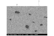
- FIG. 1 is a photograph, taken by a scanning electron microscope, of the structure of the heat dissipation material according to this embodiment.
- FIG. 2 is a schematic cross-sectional view illustrating an example of an electrostatic chuck according to an embodiment of the present invention.
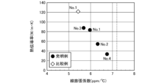
- FIG. 3 is a graph showing the measurement results of the examples and comparative examples, with the thermal conductivity on the vertical axis and the linear expansion coefficient on the horizontal axis.
- FIG. 4 is a graph showing the relationship between relative density and alloying ratio, with the vertical axis representing the relative density and the horizontal axis representing the alloying ratio.
- the inventors conducted extensive research into materials for heat dissipation components that can be used in processes that involve large heat inputs.
- the recent trend towards higher integration of semiconductors has resulted in greater heat input during etching.
- the aluminum alloys that have traditionally been used as base plate materials have poor heat resistance, and heat treatment (aging treatment) during the manufacturing stage of aluminum alloys is generally carried out at temperatures up to 200°C. For this reason, if the temperature of the base plate exceeds 200°C during the etching process, the material properties of the aluminum alloy cannot be maintained.
- the heat dissipation component in order to apply a heat dissipation component to a processing process with a large heat input, it is important that the heat dissipation component has high heat resistance, an appropriate thermal expansion coefficient, and high thermal conductivity.
- the inventors have discovered that by using a material in which Mo and Ti phases coexist and the Ti content is appropriately controlled as a heat dissipation component, a heat dissipation component with the desired characteristics can be obtained. Furthermore, the inventors have discovered that by controlling the alloying ratio of Mo and Ti within an appropriate range, a good relative density can be obtained and a highly reliable heat dissipation material can be manufactured. The present invention was made based on these findings.
- the heat dissipation material according to this embodiment has Mo as its main component, which can significantly improve its heat resistance.
- Mo is also one of the pure metals with high thermal conductivity, more than twice that of iron and more than eight times that of titanium. Therefore, by having Mo as its main component, the heat dissipation material can exhibit high heat dissipation properties.
- the inventors also discovered that, in order to obtain a heat dissipation material with a particularly desired linear expansion coefficient, it is effective to allow the Mo phase and the Ti phase to coexist, rather than completely dissolving Ti in Mo; more specifically, Ti has a larger linear expansion coefficient than Mo, and the linear expansion coefficient of the resulting alloy can be made closer to that of the material of the ceramic layer.
- Ti phase is not dispersed, the effect of adding Ti is weakened, and the linear expansion coefficient of the heat dissipation material approaches that of Mo.
- the heat dissipation material according to this embodiment is a sintered body obtained by mixing and sintering Mo powder and Ti powder, and more specifically, it is a sintered composite having a structure in which the Mo phase (body-centered cubic structure) and the Ti phase (hexagonal close-packed structure or body-centered cubic structure) coexist.
- This sintered composite has characteristics such as the inclusion of pores, so it is possible to confirm that it is a sintered body by observing the structure.
- FIG 1 is a photograph taken by a scanning electron microscope of the structure of the heat dissipation material according to invention example No. 3, which will be described later.
- the heat dissipation material according to this embodiment has a black Ti phase 2 dispersed in the Mo phase 1, which is the main component.
- this embodiment shows that a metal/metal composite material is formed.
- this Ti phase 2 has the effect of increasing the linear expansion coefficient, by adjusting the Ti content, it is possible to obtain a heat dissipation material for heat dissipation parts that is suitable for use in processing processes where a large heat input is applied.
- the Ti content in the heat dissipation material is set to 3 atomic % or more, preferably 4 atomic % or more, and more preferably 8 atomic % or more. It is more preferable to set the above.
- the Ti content in the heat dissipating material exceeds 50 atomic %, the thermal conductivity decreases and the properties required for the heat dissipating material cannot be obtained.
- the Ti content in the heat dissipation material it is possible to match the linear expansion coefficient to that of the ceramic layer (Al 2 O 3 layer or Y 2 O 3 layer, etc.), and the thermal expansion coefficient can be adjusted to the same level as that of the ceramic layer (Al 2 O 3 layer or Y 2 O 3 layer, etc.). It is possible to prevent the ceramic layer (such as an Al 2 O 3- layer or a Y 2 O 3- layer) from peeling off, and it is also possible to obtain excellent heat dissipation properties.
- the heat dissipation material according to this embodiment contains Ti in the above range, with the remainder being Mo. Therefore, it is possible to obtain excellent heat resistance, and also obtain properties that combine high thermal conductivity and an appropriate linear expansion coefficient.
- the heat dissipation material according to this embodiment does not contain Cu. If Cu is present in the chamber during the etching process, the chamber may be contaminated with Cu, which may affect the wiring structure. Therefore, the heat dissipation material according to this embodiment that does not contain Cu is particularly suitable for use in the etching process.
- the heat dissipation material according to this embodiment may contain various impurities within a range that does not impair the effects of the present invention.
- impurities include oxygen (O), nitrogen (N), and carbon (C) derived from the powder raw material.
- Fe, Si, Mn, Mg, Cl, Al, V, Mn, Ni, Nb, and the like may also be contained.
- oxygen (O) it is considered empirically preferable to suppress oxygen (O) to 3 mass% or less, and other elements to, for example, 1 mass% or less or 0.3 mass% or less, respectively, and a total of, for example, 5 mass% or less or 3 mass% or less.
- the above impurity contents are expressed in mass % when the total amount of Mo content and Ti content in the heat dissipation material according to this embodiment is taken as 100 mass %. Furthermore, so long as these elements are within the above-mentioned numerical ranges, the effects of this embodiment are not hindered even if they are intentionally added, not just when they are contained as unavoidable impurities.
- the inventors have discovered that by controlling the alloying ratio of Mo and Ti within an appropriate range, it is possible to obtain good relative density in addition to excellent thermal conductivity and linear expansion coefficient.
- the alloying ratio of Mo and Ti is described in more detail below.
- the method for measuring the alloying ratio is described below. First, the heat dissipation material after sintering is measured by X-ray diffraction (XRD). Next, the spectrum obtained by XRD is analyzed by whole powder pattern fitting (WPPF) to obtain the atomic fraction (atomic %) of the Mo phase, Mo x Ti y phase, and Ti phase. Then, using these values, the alloying ratio can be measured by the formula (1) described later.
- XRD X-ray diffraction
- WPPF whole powder pattern fitting
- a heat dissipation material with good relative density can be obtained by specifying the alloying ratio A represented by the following formula (1).
- [Mo phase] is the ratio of Mo phase in the heat dissipation material, as determined by X-ray diffraction, expressed in atomic %
- [Total Mo] is the concentration of all Mo contained in the heat dissipation material, expressed in atomic %.
- the Mo concentration in the heat dissipating material is the ratio of Mo atoms in atomic % when the total of Ti atoms and Mo atoms in the heat dissipating material is 100 atomic %
- the ratio of Mo phase in the heat dissipating material is the ratio of Mo atoms in the Mo phase in atomic % when all atoms constituting the Mo phase, Mo x Ti y phase, and Ti phase in the heat dissipating material are 100 atomic %.
- the [Mo phase] can be calculated from the mass fraction of the Mo phase among the mass fractions of the Mo phase, Mo x Ti y phase, and Ti phase (total of 100 mass%) calculated by the full pattern fitting method, using the following formula (2):
- the alloying ratio A calculated using atomic % is the same value as the alloying ratio calculated using mass % instead of atomic %.
- the heat dissipating material can be manufactured by mixing a powder containing Mo with a powder containing Ti to create a mixture, and then sintering this mixture.
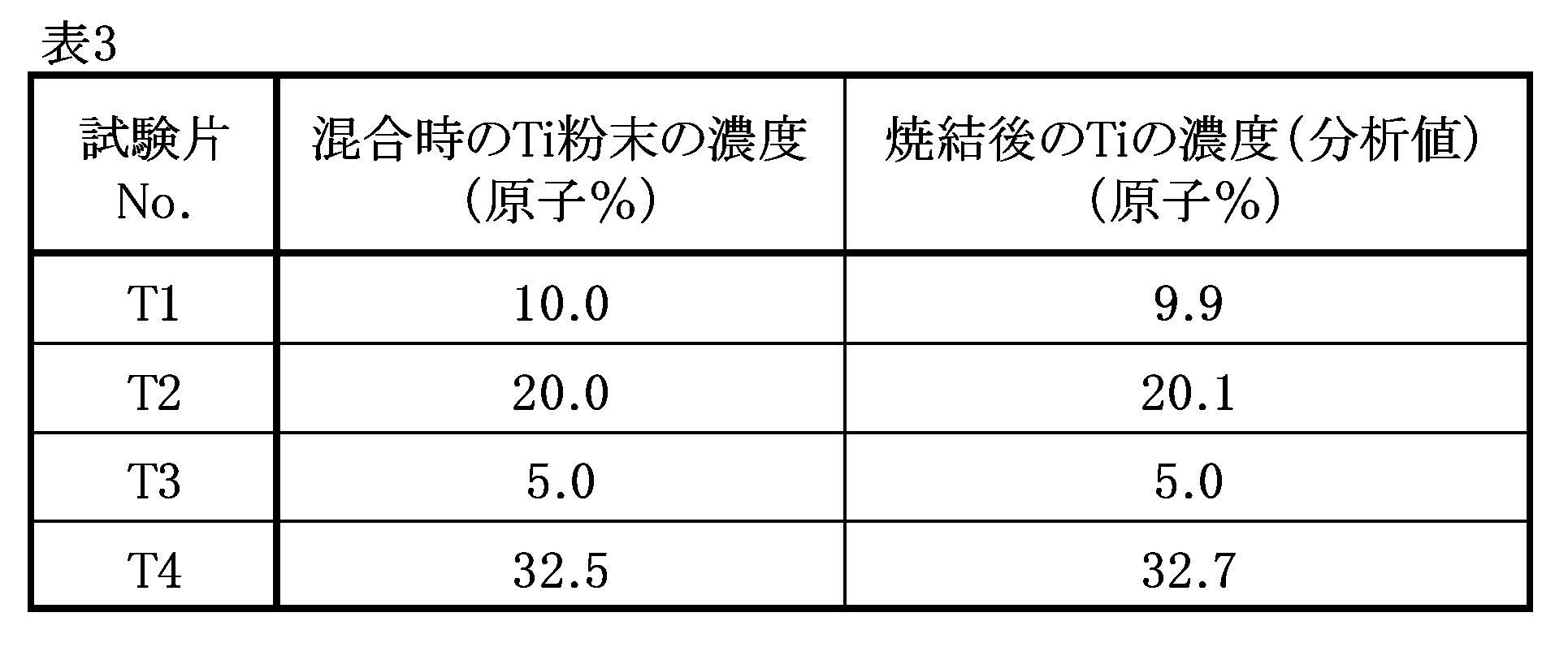
- the concentrations at the time of mixing Ti powder and Mo powder generally often become the Ti and Mo concentrations in the heat dissipating material after sintering. Therefore, if it can be confirmed that there is only a difference of a margin of error between the concentrations at the time of mixing and the concentrations in the heat dissipating material after sintering, the Mo concentration at the time the powders are mixed can be used as the Mo concentration in the heat dissipating material ([Total Mo]).
- [Mo phase] ( ⁇ Mo phase ⁇ /atomic weight of Mo)/([Mo content]/atomic weight of Mo+[Ti content]/atomic weight of Ti)
- Mo phase refers to the proportion of the Mo phase in the heat dissipating material, as determined by X-ray diffraction, expressed in atomic %.
- ⁇ Mo phase ⁇ is the mass fraction of the Mo phase obtained by XRD, and is a value expressed in mass % of the proportion of the Mo phase when the total of the Mo phase, Mo x Ti y phase, and Ti phase is 100 mass %.
- [Mo content] is the total Mo content contained in the heat dissipating material expressed in mass %.
- Ti content] is the total Ti content contained in the heat dissipating material expressed as mass %.
- the alloying ratio A calculated by the above formula (1) is 15% or more, a higher relative density can be obtained, and the occurrence of cracks, breakage, etc. due to the load of thermal stress or mechanical stress can be suppressed. Therefore, the alloying ratio A calculated by the above formula (1) is preferably 15% or more, more preferably 30% or more, and even more preferably 40% or more. In addition, when the alloying ratio A calculated by the above formula (1) is 80% or less, the temperature required for sintering can be prevented from becoming too high or the time can be prevented from becoming too long, and the wear of the sintering mold can be suppressed and good productivity can be maintained.
- the alloying ratio A calculated by the above formula (1) is preferably 80% or less, more preferably 70% or less, and even more preferably 60% or less.
- the alloying ratio is due to atomic diffusion between Mo and Ti, and can be controlled by changing the temperature and time required for processing in subsequent processes that apply thermal load, such as the sintering process and bonding that is performed as necessary.
- the thermal load for sintering and bonding can be performed under conditions that correspond to the equipment and powder characteristics, with a temperature of 800°C to 1400°C, a holding time of 5 minutes to 16 hours, and a pressure of 2 MPa to 50 MPa as guidelines.
- the relative density D can be obtained by dividing the value of the density dm obtained by the underwater substitution method (Archimedes method) or the like by the theoretical density dt and expressing the result as a percentage. That is, the relative density D can be expressed by the following formula (3).
- the theoretical density dt can be calculated by the following formula (4).
- Formula (4): d t 100/([Ti content]/[Ti specific gravity]+[Mo content]/[Mo specific gravity])
- the Ti content is the amount of Ti contained in the heat dissipating material expressed in mass%
- the Ti specific gravity is the specific gravity of pure Ti.
- the "Mo content” is a value expressed in mass% of the Mo content contained in the heat dissipating material
- the "Mo specific gravity” is a value expressed in mass% of pure Mo. This is the value.
- the relative density D is preferably 98% or more, more preferably 98.5% or more, even more preferably 99% or more, and even more preferably 99.5% or more. Furthermore, the relative density D is preferably 100.0% or more, more preferably 100.5% or more, and even more preferably 101.0% or more.
- the heat dissipation component according to this embodiment is obtained by machining the heat dissipation material (sintered composite) according to the above embodiment, and has excellent heat resistance, a large thermal conductivity, and an appropriate linear expansion coefficient. Therefore, when this heat dissipation component is used, heat can be sufficiently dissipated in a processing process with a large heat input. In addition, since this heat dissipation component has an appropriate linear expansion coefficient, even if the influence of thermal expansion is large in a process with a large heat input, the size change rate of the surrounding material and the size change rate of the heat dissipation component are close to each other. Therefore, it is possible to suppress the occurrence of distortion between the heat dissipation component and the surrounding material, and to prevent peeling or cracking of the surrounding material.
- FIG. 2 is a schematic cross-sectional view showing an example of an electrostatic chuck according to an embodiment of the present invention.
- an electrostatic chuck 10 has a base plate 11 made of the above-mentioned heat dissipation component, a ceramic layer 12 provided on the base plate 11, and an electrode 14 that generates static electricity on a surface 12a of the ceramic layer 12.
- a coolant flow path 13 is provided inside the base plate 11.
- an electrostatic chuck is a device that grips a member by utilizing the force of static electricity, and the electrostatic chuck can be applied to semiconductor manufacturing equipment, electrostatic robot hands, etc.
- an etching equipment has the electrostatic chuck 10 according to the present embodiment and a plasma generation and processing chamber in which the electrostatic chuck 10 is arranged.
- a silicon wafer (not shown) is placed on the electrostatic chuck 10 arranged in the plasma generation and processing chamber, and a voltage is applied to the electrode 14 to generate static electricity on the surface of the ceramic layer 12, thereby fixing the silicon wafer.
- the wafer surface is etched by using plasma in the plasma generation and processing chamber. Since the plasma is high temperature and the temperature rises during etching, the wafer is cooled by flowing a coolant through the coolant flow passage 13 formed in the base plate 11.
- the heat input during etching is large due to the recent high integration of semiconductors, so the base plate is required to have high heat resistance.
- the heat dissipation material and heat dissipation member according to this embodiment are suitable for use in processing steps that involve large heat input. That is, by using the electrostatic chuck according to this embodiment, the silicon wafer can be effectively cooled even in high-temperature etching steps that correspond to the miniaturization and high integration of semiconductor devices.
- the heat dissipation parts have an appropriate linear expansion coefficient, it is possible to suppress the occurrence of distortion between the ceramic layer and the base plate even in the above-mentioned etching step, and it is possible to prevent the ceramic layer from peeling or cracking.
- the electrostatic chuck according to this embodiment is particularly preferably used in an etching device.
- the method for producing a heat dissipation material is a method for producing the above-mentioned heat dissipation material, and includes a mixing step of mixing a powder containing Mo and a powder containing Ti to obtain a mixture, and a sintering step of sintering the mixture.
- the sintering method used in the sintering process is not particularly limited, and for example, Spark Plasma Sintering (SPS), hot pressing, hot isostatic pressing (HIP), etc. can be used.
- the sintering conditions in the sintering process are also not particularly limited, but the sintering can be carried out under conditions according to the characteristics of the equipment and the characteristics of the powder, with the sintering temperature being approximately 800°C to 1600°C, the sintering holding time being 5 minutes to 3 hours, and the pressure being 10 MPa to 50 MPa as guidelines.
- the Mo-containing powder and Ti-containing powder used as heat dissipation material include powders containing oxygen, nitrogen, carbon, etc., derived from the powder raw materials as impurities.
- alloy powders may be used as heat dissipation material materials as long as the effects of the present invention are not impaired.
- a heat dissipation part such as a base plate.
- a ceramic layer on the upper surface of the obtained heat dissipation part by diffusion bonding, and then performing finishing processing by cutting, it is possible to manufacture an electrostatic chuck in which the base plate and the ceramic layer are bonded.
- methods for bonding the base plate and ceramics include brazing, bonding with an adhesive, and fixing with screws.
- the heat dissipation material, heat dissipation component, electrostatic chuck, and method for manufacturing a heat dissipation material according to the present invention are not limited to the above-described embodiments, and can be modified as desired without departing from the gist of the present invention.
- the heat dissipation component is used as a base plate of an electrostatic chuck used during etching in a semiconductor manufacturing device, but the present invention is not limited thereto, and the heat dissipation material and heat dissipation component of the present invention can be used as any heat dissipation material and heat dissipation component. Since the heat dissipation material of the present invention has the above-mentioned characteristics, it is suitably used as a material for a heat dissipation component used in a processing step in which a particularly large heat input is applied.
- the heat dissipation material according to the present invention will be explained in more detail below with examples and comparative examples. However, the present invention is not limited to these examples, and modifications can be made within the scope of the present invention, and all of these modifications are included within the technical scope of the present invention. Furthermore, the heat dissipation material and its manufacturing conditions described below are examples, and the present invention is not limited to the following examples.
- the specific heat at room temperature was measured by a differential scanning calorimetry (DSC) and the thermal diffusivity was measured by a flash method, and the thermal conductivity was calculated from these values.
- DSC differential scanning calorimetry
- the obtained sintered body was mirror-polished, and the material structure was observed by taking a backscattered electron image using a scanning electron microscope.
- the thermal conductivity of pure Al shown in Table 2 below is measured at 200°C, and the linear expansion coefficient is measured at 20 to 400°C.
- the linear expansion coefficient of Al alloys shown in Table 2 below is measured at 20 to 300°C.
- FIG. 3 is a graph showing the measurement results of the invention examples and the comparative examples, with the thermal conductivity on the vertical axis and the linear expansion coefficient on the horizontal axis.
- the dotted line in the figure indicates the linear expansion coefficient of alumina.
- FIG. 1 is a micrograph of the structure of the invention example No. 3. As a result of observing the material structures of the invention examples No. 1 to 4, it was confirmed that the Mo phase and the Ti phase coexisted in all the invention examples, as in the micrograph shown in FIG. 1. As shown in Tables 1 and 2 above, the linear expansion coefficients of the sintered bodies of the invention examples No. 1 to 4 were larger than that of the sintered body of the comparative example No.
- the linear expansion coefficients of the sintered bodies of the invention examples No. 1 to 4 were very close to the linear expansion coefficient of alumina , which is the comparative example No. 2, compared to the conventional materials of the comparative examples No. 3 and 4. Furthermore, the linear expansion coefficients of the sintered bodies of the invention examples No. 1 to 4 were very close to that of the comparative example No. 2, which is the linear expansion coefficient of alumina, compared to the conventional materials of the comparative examples No. 3 and 4. When the sintered bodies No. 1 to No. 4 are compared, it was confirmed that the linear expansion coefficient increases with increasing Ti concentration in the sintered body, approaching the linear expansion coefficient of Al 2 O 3 .
- the above results show that when heat dissipation components are made using the sintered bodies of invention examples 1 to 4, the resulting heat dissipation components have excellent heat dissipation properties.
- the linear expansion coefficient is close to that of the ceramic layer made of alumina that is bonded to the heat dissipation components, it is possible to prevent the occurrence of cracks and peeling in the ceramic layer.
- the sintered bodies of invention examples 1 to 4 are mainly composed of Mo and contain a specified amount of Ti, both of which are highly heat-resistant components, and therefore have high heat resistance.
- the sintered bodies of invention examples 1 to 4 do not contain Cu, when heat dissipation components made of these sintered bodies are used in the etching process of semiconductor manufacturing equipment, contamination inside the chamber can be suppressed.
- a Mo-Ti sintered body (heat dissipation material) was produced by mixing pure Mo powder and pure Ti powder and sintering the mixture through a powder process using hot pressing and SPS.
- the concentrations of Ti powder and Mo powder when mixed are considered to be the Ti and Mo concentrations in the heat dissipation material after sintering.
- the relative density D and the alloying ratio A of the obtained Mo-Ti sintered body (heat dissipation material) were calculated.
- the relative density D can be calculated by the following formula (3).
- Ti content refers to the content of Ti contained in the heat dissipating material, and is the content of Ti powder in the raw material powder expressed in mass%.
- the Ti specific gravity is the value representing the specific gravity of pure Ti.
- the Mo content is the content of Mo contained in the heat dissipation material.
- the content of Mo powder in the powder was expressed as a value expressed in mass %.
- [Mo specific gravity] is a value expressing the specific gravity of pure Mo.
- the specific gravity of pure Ti is 4.508, The specific gravity of pure Mo was 10.222.
- the sintered body was subjected to measurement by X-ray diffraction (XRD), and the concentrations of Mo phase, Mo x Ti y phase, and Ti phase were measured by analysis by the WPPF method using the spectrum with a 2 ⁇ angle of 20 to 140°.
- XRD X-ray diffraction
- the alloying ratio A was calculated using the following formula (1) from the content of the Mo phase in the sintered body and the concentration of all Mo contained in the sintered body ([total Mo] (atomic%)) obtained by the above XRD analysis.
- [Mo phase] is a value expressed in atomic % of the ratio of Mo atoms constituting the Mo phase in the sintered body specified by X-ray diffraction
- [total Mo] is a value expressed in atomic % of the concentration of all Mo contained in the sintered body.
- ⁇ Mo phase ⁇ is the mass fraction of the Mo phase obtained by XRD, and is a value expressed in mass % when the total of the Mo phase, Mo x Ti y phase, and Ti phase is 100 mass %.
- Mo content is a value expressed in mass % of the content of all Mo contained in the sintered body.
- Ti content is a value expressed in mass % of the content of all Ti contained in the sintered body.
- concentration of Mo powder in the raw material powder can be used as the concentration of Mo in the sintered body.
- Example 21 corresponds to Example 4 in the above-mentioned Example 1
- Example 29 corresponds to Example 3 in the above-mentioned Example 1.
- Figure 4 is a graph showing the relationship between relative density and alloying ratio, with the vertical axis representing the relative density and the horizontal axis representing the alloying ratio. As shown in Figure 4, as the alloying ratio increases, the relative density value also increases, approaching 100%. Furthermore, in the inventive examples in which the alloying ratio is 15-80%, as shown by the arrow in Figure 4, a particularly good relative density was shown. Furthermore, in the range of the alloying ratio of 30% or more, the relative density became even higher, and a value close to or exceeding 100% was obtained.
- a heat dissipation material in which Mo and Ti phases coexist can be obtained by controlling the Ti content within a predetermined range and further controlling the alloying ratio within an appropriate range, resulting in a sound heat dissipation material that not only has excellent thermal conductivity and linear expansion coefficient, but also has a high relative density.
- a base plate using the heat dissipation material obtained in this way has no risk of refrigerant leakage, and can suppress the occurrence of cracks and fractures that occur when thermal or mechanical stress is applied, thereby extending the life of the base plate and improving its reliability.
Landscapes
- Chemical & Material Sciences (AREA)
- Engineering & Computer Science (AREA)
- Materials Engineering (AREA)
- Mechanical Engineering (AREA)
- Metallurgy (AREA)
- Organic Chemistry (AREA)
- Powder Metallurgy (AREA)
- Drying Of Semiconductors (AREA)
- Container, Conveyance, Adherence, Positioning, Of Wafer (AREA)
Abstract
Description
Tiを3原子%以上50原子%以下含有し、
残部がMoを含有することを特徴とする、放熱材料。
O:Mo含有量とTi含有量との合計量を100質量%とした場合に、0質量%以上3質量%以下、
N、C、Fe、Si、Mn、Mg、Cl、Al、V、Mn、NiおよびNb:Mo含有量とTi含有量との合計量を100質量%とした場合に、それぞれ0質量%以上1質量%以下、および
残部:Moおよび不可避的不純物からなることを特徴とする、[1]に記載の放熱材料。
Tiを3原子%以上50原子%以下含有し、
残部がMoであることを特徴とする、放熱材料。
式(1):A=(1-[Mo相]/[全Mo])×100
Moを含む粉末と、Tiを含む粉末とを混合して、混合物を得る混合工程と、
前記混合物を焼結する焼結工程と、を備えることを特徴とする、放熱材料の製造方法。
アルミニウム合金のうち、耐熱性が高いと言われる2000系アルミ合金の引張耐力は、200℃の温度において200MPaまで低下する(小山克己,“高強度・耐熱性アルミニウム合金”,Furukawa-Sky Review,No.6,2010,p.13,図7)。
一方、Moは融点が2623℃の高融点金属であり、200℃程度の温度において極めて優れた耐熱性を有する。具体的に、Moの引張強さは、200℃において550MPa以上の値を有する(村上孝士ら,“モリブデン及びモリブデン合金”,溶接学会誌,第57巻(1988),第4号,p.293,図2)。
放熱材料中のTi含有量が3原子%未満であると、放熱材料の線膨張係数を増加させる作用を十分に得ることができず、ベースプレートからのセラミック層(Al2O3層又はY2O3層等)の剥離や、セラミック層の割れが発生する虞がある。したがって、放熱材料中のTi含有量は、3原子%以上とし、4原子%以上とすることが好ましく、8原子%以上とすることがより好ましい。
一方、放熱材料中のTi含有量が50原子%を超えると、熱伝導率が低下し、放熱材料として要求される特性を得ることができない。したがって、放熱材料中のTi含有量は、50原子%以下とし、45原子%以下とすることが好ましく、35原子%以下とすることがより好ましい。
このように、放熱材料中のTi含有量を適切に調整することにより、セラミック層(Al2O3層又はY2O3層等)と同程度まで線膨張係数を合わせることができ、ベースプレートからセラミック層(Al2O3層又はY2O3層等)が剥離することを抑制することができるとともに、優れた放熱性を得ることができる。
本実施形態に係る放熱材料は、上記範囲でTiを含有し、残部がMoからなるものである。したがって、優れた耐熱性が得られるとともに、大きな熱伝導率と適切な線膨張係数を兼ね備えた特性を得ることができる。
なお、上記不純物の含有量は、本実施形態に係る放熱材料におけるMo含有量とTi含有量との合計量を100質量%とした場合の、不純物含有量を質量%で表したものとする。
また、これらの元素は、上記数値範囲内であれば、不可避的不純物として含有される場合だけではなく、積極的に添加された場合であっても、本実施形態の効果を妨げない。
純Mo粉末と純Ti粉末を混合した混合粉は、焼結段階で原子拡散が生じ、MoとTiとの間に合金化した領域が形成される。本発明者らは、この合金化した領域は、純Mo単体に比べて熱間における変形抵抗が小さく、合金化率が増加するほど焼結が促進され、相対密度が向上することを見出した。すなわち、相対密度が低い放熱材料を含む放熱部品をベースプレートに使用した場合に、ベースプレートを冷却するための冷媒が漏れたり、ベースプレートの繰り返しの使用に伴う熱応力や機械的な応力などによって、亀裂や破壊が助長される懸念がある。
したがって、良好な相対密度を有する放熱材料を得ることは、信頼性の高いベースプレートを製造することに繋がる。本明細書中において、合金化率とは、放熱材料に含まれる全てのMoのうち、合金化によって消費されたMoの割合を定義したものである。
より詳細には、[Mo相]は、上記全パターンフィッティング法で求められたMo相、MoxTiy相及びTi相の質量分率(合計で100質量%)のうちのMo相の質量分率から、下記式(2)によって求めることができる。ただし、下記式(1)において、原子%を用いて算出される合金化率Aは、原子%の代わりに質量%を用いて算出される合金化率と同じ値となる。
式(2):[Mo相]=({Mo相}/Moの原子量)/([Mo含有量]/Moの原子量+[Ti含有量]/Tiの原子量)
ただし、上記式(2)において、[Mo相]とは、X線回折法により特定される、放熱材料中のMo相の割合を原子%で表した値である。
{Mo相}とは、XRDで得られるMo相の質量分率であり、Mo相、MoxTiy相、及びTi相の合計を100質量%とした場合のMo相の割合を質量%で表した値である。
[Mo含有量]とは、放熱材料中に含有される全てのMoの含有量を質量%で表した値である。
[Ti含有量]とは、放熱材料中に含有される全てのTiの含有量を質量%で表した値である。
また、上記式(1)により算出される合金化率Aが80%以下であると、焼結に要する温度が高くなりすぎることや、時間が長くなりすぎることを防止でき、焼結型の損耗を抑制し、良好な生産性を維持することができる。したがって、上記式(1)により算出される合金化率Aは、80%以下とすることが好ましく、70%以下とすることがより好ましく、60%以下とすることがさらに好ましい。このような合金化率に制御することによって、良好な熱伝導率・線膨張係数に加えて、高い相対密度を有する放熱材料が得られる。そして、このような放熱材料を含む放熱部品をベースプレートに使用した場合に、ベースプレートとしての性能及び信頼性を向上させることができる。
ただし、上記式(4)において、[Ti含有量]とは、放熱材料中に含有されるTiの含有量を質量%で表した値であり、[Ti比重]とは、純Tiの比重を表した値である。また、[Mo含有量]とは、放熱材料中に含有されるMoの含有量を質量%で表した値であり、[Mo比重]とは、純Moの比重を表した値である。
本実施形態に係る放熱部品は、上記本実施形態に係る放熱材料(焼結複合体)を機械加工して得られるものであり、優れた耐熱性を有するとともに、大きな熱伝導率と適切な線膨張係数を兼ね備えた特性を有する。したがって、この放熱部品を使用すると、入熱の大きな処理工程において十分に放熱することができる。また、この放熱部品は適切な線膨張係数を有するため、入熱が大きい工程において熱膨張の影響が大きくなる場合であっても、周囲の素材のサイズ変化率と放熱部品のサイズ変化率とが近い値となる。したがって、放熱部品と周囲の素材との間でひずみが生じることを抑制することができ、周囲の素材に剥離や割れが発生することを防止することができる。
図2は、本発明の実施形態に係る静電チャックの一例を示す模式的断面図である。図2に示すように、静電チャック10は、上記放熱部品からなるベースプレート11と、このベースプレート11の上に設けられたセラミック層12と、セラミック層12の表面12aに静電気を発生させる電極14と、を有する。ベースプレート11の内部には、冷媒流路13が設けられている。なお、静電チャックとは、静電気の力を利用して部材を把持するものであり、静電チャックは、半導体製造装置や、静電気ロボットハンド等に適用することが可能である。
本実施形態に係る放熱材料の製造方法は、上記放熱材料を製造する方法であり、Moを含む粉末と、Tiを含む粉末とを混合して、混合物を得る混合工程と、混合物を焼結する焼結工程と、を備える。
上述した実施形態では、放熱部品を、半導体製造装置のエッチング時に用いられる静電チャックのベースプレートとして使用した態様を説明したが、本発明はこれに限定されず、本発明の放熱材料及び放熱部品は、任意の放熱材料、放熱部品として使用できる。本発明の放熱材料は、上述した特徴を有しているので、特に大きい入熱が与えられる処理工程に用いられる放熱部品の材料として好適に使用される。
(放熱材料の製造)
まず、種々の組成でMo-Ti焼結複合体が形成されるように、Mo粉末とTi粉末とを混合して混合物を得た。その後、得られた混合物に対して、ホットプレス法又はSPS法を用いた粉末焼結法により焼結を行い、発明例No.1~発明例No.4の焼結体を製造した。また、Mo粉末のみを焼結して焼結体を製造し、比較例No.1とした。比較例No.2、比較例No.3及び比較例No.4は、それぞれ、公知のアルミナ(Al2O3)、純アルミニウム及び2000系アルミニウム合金であってジュラルミンとして知られる2024-T6合金とした。
なお、発明例No.1、発明例No.2、及び比較例No.1は、ホットプレス法により焼結を行い、発明例No.3及び発明例No.4は、SPS法により焼結を行った。
発明例No.1~発明例No.4について、誘導結合プラズマ(ICP:Inductively Coupled Plasma)発光分光分析法により成分を分析した。発明例における放熱材料の成分の分析結果、及び比較例の焼結体の材料を下記表1及び表2に示す。なお、表1に示す組成は、Ti原子とMo原子との合計を100原子%とした場合のTi原子の割合及びMo原子の割合を原子%で表したものである。
得られた焼結体について、示差走査熱量計(DSC:Differential scanning calorimetry)により、室温での比熱を測定するとともに、フラッシュ法により熱拡散率を測定し、これらの値から熱伝導率を算出した。
得られた焼結体について、熱機械分析法(TMA法:Thermomechanical Analysis)により、40℃~400℃の線膨張係数を測定した。
得られた焼結体を鏡面研磨し、走査型電子顕微鏡を用いた反射電子像を撮影することにより材料組織を観察した。

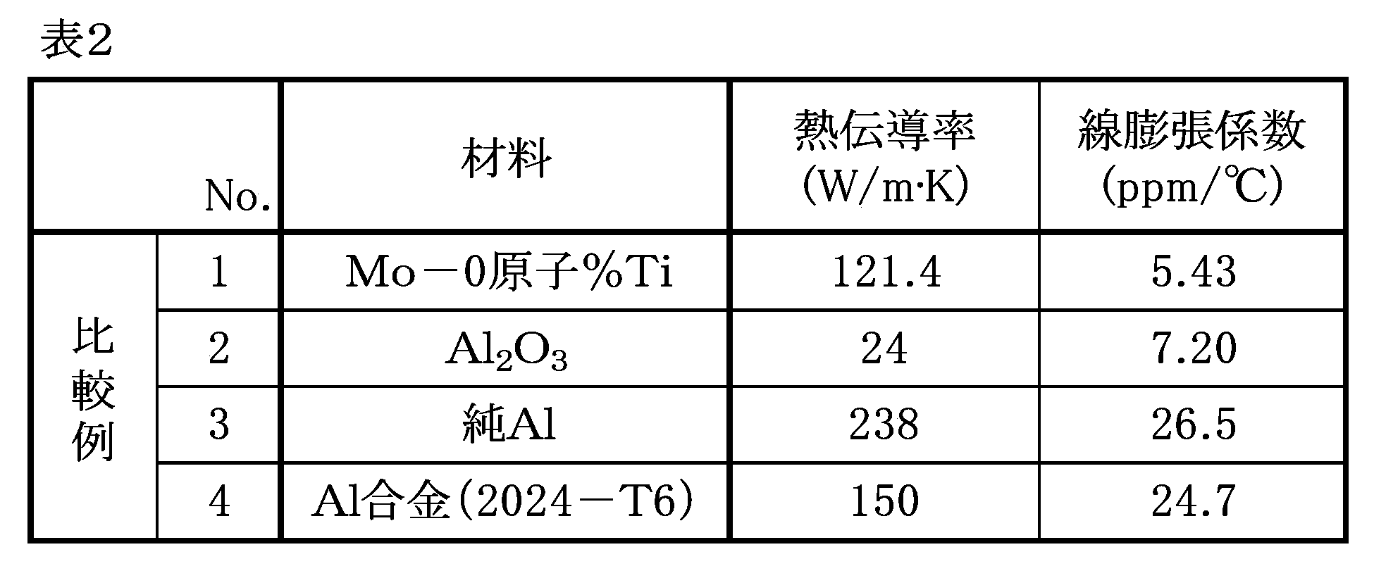
図3は、縦軸を熱伝導率とし、横軸を線膨張係数とした場合の、発明例及び比較例の測定結果を示すグラフ図である。なお、図中の点線はアルミナの線膨張係数を示している。また、図1は、発明例No.3の組織を撮影した顕微鏡写真である。発明例No.1~4について材料組織の観察を行った結果、図1に示す顕微鏡写真と同様に、全ての発明例においてMo相とTi相とが共存していることを確認することができた。また、上記表1及び表2に示すように、発明例No.1~4の焼結体の線膨張係数は、比較例No.1のTiが含有されていない焼結体と比較して、線膨張係数が大きい値となり、静電チャックの材料として使用されるAl2O3の線膨張係数に近づく値となった。特に、発明例No.1~4の焼結体の線膨張係数は、比較例No.3及び4の従来材と比較して、比較例No.2であるアルミナの線膨張係数に極めて近い値となった。さらに、発明例No.1~4の焼結体を比較すると、焼結体中のTiの濃度の増加にともなって線膨張係数が増加し、Al2O3の線膨張係数に近づいていることが確認できた。
(放熱材料の製造)
純Mo粉末と純Ti粉末を混合して、ホットプレスとSPSを用いた粉末プロセスで焼結することにより、Mo-Ti焼結体(放熱材料)を製造した。
上記放熱材料の製造とは別に、種々の比率でMo粉末とTi粉末とを混合し、Mo粉末とTi粉末との混合時におけるTi粉末の濃度を算出した。また、混合した混合物に対して、ホットプレスとSPSを用いた粉末プロセスで焼結することにより、焼結体の試験片を製造した。その後、各試験片について、誘導結合プラズマ(ICP)発光分光分析法によりTiの濃度を分析し、上記Ti粉末の濃度と比較した。混合時における濃度の算出結果と、焼結後のTiの濃度の分析結果を下記表3に示す。
得られたMo-Ti焼結体(放熱材料)について、相対密度D及び合金化率Aを算出した。相対密度Dは、下記式(3)により算出することができる。
ただし、dmは、水中置換法により測定された焼結体の密度であり、dtは、下記式(4)により算出される理論密度dtである。
ただし、上記式(4)において、[Ti含有量]とは、放熱材料中に含有されるTiの含有量であり、ここでは、原料粉末中のTi粉末の含有量を質量%で表した値を用いた。[Ti比重]とは、純Tiの比重を表した値である。また、[Mo含有量]とは、放熱材料中に含有されるMoの含有量であり、ここでは、原料粉末中のMo粉末の含有量を質量%で表した値を用いた。[Mo比重]とは、純Moの比重を表した値である。なお、純Tiの比重は、4.508とし、純Moの比重は、10.222とした。
解析プログラム:Materials Data Inc.(MDI)社製 JADE
PRO(バージョン8)
データベース:ICDD PDF-4+
・XRDによる測定条件
微小部X線回折装置:株式会社リガク製 RINT-RAPIDII
コリメーター径:300μm
ω角:20~25°(2°/sec)
φ角:回転(1°/sec)
式(2):[Mo相]=({Mo相}/Moの原子量)/([Mo含有量]/Moの原子量+[Ti含有量]/Tiの原子量)
熱伝導率及び線膨張係数は、上記第1実施例と同様の方法で測定した。発明例No.21~29について、種々の測定結果及び算出結果を下記表4に示す。なお、下記表4において、発明例No.21は、上記第1実施例における発明例No.4であり、発明例No.29は、上記第1実施例における発明例No.3である。

図4は、縦軸を相対密度とし、横軸を合金化率とした場合の、相対密度と合金化率との関係を示すグラフ図である。図4に示すように、合金化率が増加すると、相対密度の値も大きくなり、100%に近づいていることが分かる。また、図4中に矢印の範囲で示す、合金化率が15~80%である発明例においては、特に良好な相対密度を示した。さらに、合金化率が30%以上の範囲では、相対密度はより一層高くなり、100%に近い値又はそれ以上の値を得ることができた。
2 Ti相
10 静電チャック
11 ベースプレート
13 冷媒流路
12 セラミック層
14 電極
Claims (8)
- Mo相とTi相とが共存しており、
Tiを3原子%以上50原子%以下含有し、
残部がMoを含有することを特徴とする、放熱材料。 - Ti:Ti含有量とMo含有量との合計量を100原子%とした場合に、3原子%以上50原子%以下、
O:Mo含有量とTi含有量との合計量を100質量%とした場合に、0質量%以上3質量%以下、
N、C、Fe、Si、Mn、Mg、Cl、Al、V、Mn、NiおよびNb:Mo含有量とTi含有量との合計量を100質量%とした場合に、それぞれ0質量%以上1質量%以下、および
残部:Moおよび不可避的不純物からなることを特徴とする、請求項1に記載の放熱材料。 - Mo相とTi相とが共存しており、
Tiを3原子%以上50原子%以下含有し、
残部がMoであることを特徴とする、放熱材料。 - X線回折法により測定される、放熱材料中の前記Mo相の割合を原子%で[Mo相]とし、放熱材料中に含有される全ての前記Moの濃度を原子%で[全Mo]とする場合に、下記式(1)により表される合金化率Aが15%以上80%以下であることを特徴とする、請求項1~3のいずれか1項に記載の放熱材料。
式(1):A=(1-[Mo相]/[全Mo])×100 - ベースプレートと、前記ベースプレートの上に設けられたセラミック層と、前記セラミック層の表面に静電気を発生させる電極と、を有する静電チャックに使用される放熱材料であって、
前記ベースプレートの材料として使用されることを特徴とする、請求項1~3のいずれか1項に記載の放熱材料。 - 請求項1~3のいずれか1項に記載の放熱材料を含むことを特徴とする、放熱部品。
- 請求項6に記載の放熱部品からなるベースプレートと、前記ベースプレートの上に設けられたセラミック層と、前記セラミック層の表面に静電気を発生させる電極と、を有することを特徴とする、静電チャック。
- 請求項1~3のいずれか1項に記載の放熱材料を製造する方法であって、
Moを含む粉末と、Tiを含む粉末とを混合して、混合物を得る混合工程と、
前記混合物を焼結する焼結工程と、を備えることを特徴とする、放熱材料の製造方法。
Priority Applications (2)
| Application Number | Priority Date | Filing Date | Title |
|---|---|---|---|
| KR1020257039815A KR20260003198A (ko) | 2023-06-05 | 2024-05-14 | 방열 재료, 방열 부품 및 방열 재료의 제조 방법 |
| CN202480037026.5A CN121335996A (zh) | 2023-06-05 | 2024-05-14 | 散热材料、散热部件、静电吸盘及散热材料的制造方法 |
Applications Claiming Priority (4)
| Application Number | Priority Date | Filing Date | Title |
|---|---|---|---|
| JP2023-092511 | 2023-06-05 | ||
| JP2023092511 | 2023-06-05 | ||
| JP2024059528A JP2024174805A (ja) | 2023-06-05 | 2024-04-02 | 放熱材料、放熱部品、静電チャック及び放熱材料の製造方法 |
| JP2024-059528 | 2024-04-02 |
Publications (1)
| Publication Number | Publication Date |
|---|---|
| WO2024252861A1 true WO2024252861A1 (ja) | 2024-12-12 |
Family
ID=93795323
Family Applications (1)
| Application Number | Title | Priority Date | Filing Date |
|---|---|---|---|
| PCT/JP2024/017756 Ceased WO2024252861A1 (ja) | 2023-06-05 | 2024-05-14 | 放熱材料、放熱部品、静電チャック及び放熱材料の製造方法 |
Country Status (5)
| Country | Link |
|---|---|
| JP (2) | JP2024174805A (ja) |
| KR (1) | KR20260003198A (ja) |
| CN (1) | CN121335996A (ja) |
| TW (1) | TWI901167B (ja) |
| WO (1) | WO2024252861A1 (ja) |
Citations (6)
| Publication number | Priority date | Publication date | Assignee | Title |
|---|---|---|---|---|
| JPS57111943A (en) * | 1980-11-21 | 1982-07-12 | Gte Laboratories Inc | Vacuum sealing assembly |
| JP2000335981A (ja) * | 1999-05-26 | 2000-12-05 | Toto Ltd | セラミック接合部品 |
| JP2003229474A (ja) * | 2002-02-01 | 2003-08-15 | Nippon Tungsten Co Ltd | 冷却ユニット部材 |
| JP2005029862A (ja) * | 2003-07-10 | 2005-02-03 | Hitachi Metals Ltd | 薄膜形成用スパッタリングターゲット |
| JP2008103713A (ja) * | 2006-10-06 | 2008-05-01 | Ngk Insulators Ltd | 基板載置台 |
| JP2010261107A (ja) * | 2010-07-01 | 2010-11-18 | Sanyo Special Steel Co Ltd | 高密度固化成形体の製造方法 |
Family Cites Families (2)
| Publication number | Priority date | Publication date | Assignee | Title |
|---|---|---|---|---|
| JP2936295B2 (ja) * | 1991-09-18 | 1999-08-23 | 株式会社クボタ | 低圧鋳造装置の給湯路部材用耐食合金 |
| JP2017103389A (ja) | 2015-12-03 | 2017-06-08 | 新光電気工業株式会社 | 静電チャック及び半導体製造装置 |
-
2024
- 2024-04-02 JP JP2024059528A patent/JP2024174805A/ja not_active Ceased
- 2024-05-14 WO PCT/JP2024/017756 patent/WO2024252861A1/ja not_active Ceased
- 2024-05-14 KR KR1020257039815A patent/KR20260003198A/ko active Pending
- 2024-05-14 CN CN202480037026.5A patent/CN121335996A/zh active Pending
- 2024-06-03 TW TW113120402A patent/TWI901167B/zh active
-
2025
- 2025-01-10 JP JP2025004176A patent/JP7719318B2/ja active Active
Patent Citations (6)
| Publication number | Priority date | Publication date | Assignee | Title |
|---|---|---|---|---|
| JPS57111943A (en) * | 1980-11-21 | 1982-07-12 | Gte Laboratories Inc | Vacuum sealing assembly |
| JP2000335981A (ja) * | 1999-05-26 | 2000-12-05 | Toto Ltd | セラミック接合部品 |
| JP2003229474A (ja) * | 2002-02-01 | 2003-08-15 | Nippon Tungsten Co Ltd | 冷却ユニット部材 |
| JP2005029862A (ja) * | 2003-07-10 | 2005-02-03 | Hitachi Metals Ltd | 薄膜形成用スパッタリングターゲット |
| JP2008103713A (ja) * | 2006-10-06 | 2008-05-01 | Ngk Insulators Ltd | 基板載置台 |
| JP2010261107A (ja) * | 2010-07-01 | 2010-11-18 | Sanyo Special Steel Co Ltd | 高密度固化成形体の製造方法 |
Also Published As
| Publication number | Publication date |
|---|---|
| JP2025065139A (ja) | 2025-04-17 |
| TW202449186A (zh) | 2024-12-16 |
| JP2024174805A (ja) | 2024-12-17 |
| CN121335996A (zh) | 2026-01-13 |
| TWI901167B (zh) | 2025-10-11 |
| KR20260003198A (ko) | 2026-01-06 |
| JP7719318B2 (ja) | 2025-08-05 |
Similar Documents
| Publication | Publication Date | Title |
|---|---|---|
| Liu et al. | Formation of transition layer and its effect on mechanical properties of AlCoCrFeNi high-entropy alloy/Al composites | |
| CN111050957B (zh) | 层叠造型用Ni基耐腐蚀合金粉末、使用其的层叠造型品和半导体制造装置用构件的制造方法 | |
| JP5447743B1 (ja) | Fe−Co系合金スパッタリングターゲット材およびその製造方法 | |
| US20200290118A1 (en) | Alloy article, product formed of said alloy article, and fluid machine having said product | |
| JP4415303B2 (ja) | 薄膜形成用スパッタリングターゲット | |
| CN110438387A (zh) | 硅化物析出强化难熔高熵合金及其制备方法 | |
| Cai et al. | Microstructure and properties of Al/Sip composites for thermal management applications | |
| JPWO2007049761A1 (ja) | モリブデン合金およびそれを用いたx線管回転陽極ターゲット、x線管並びに溶融るつぼ | |
| TWI715466B (zh) | 鉬合金靶材及其製造方法 | |
| JP7672390B2 (ja) | 複合材料、及び放熱部材 | |
| JP4647724B2 (ja) | 半導体配線用バリア膜、焼結体スパッタリングターゲット及びスパッタリングターゲットの製造方法 | |
| JP7719318B2 (ja) | 放熱材料、放熱部品及び放熱材料の製造方法 | |
| WO2021066142A1 (ja) | 耐熱合金、耐熱合金粉末、耐熱合金成形体およびその製造方法 | |
| JP2008255440A (ja) | MoTi合金スパッタリングターゲット材 | |
| JP2011084754A (ja) | スパッタリングターゲットの製造方法 | |
| CN116397133B (zh) | 一种基于slm成形的瓷粉增强钛基合金复合材料及其制备方法 | |
| JP2025144282A (ja) | 金属/セラミックス接合体、ろう材、および、金属/セラミックス接合体の製造方法 | |
| Chuang et al. | Low-Temperature Die Bonding of SiC Chips with DBC Ceramic Substrates Using High-Density Ag (111) Nanotwinned Films | |
| JP2022130467A (ja) | TiAl合金材及びその製造方法、並びにTiAl合金材の鍛造方法 | |
| Hu et al. | Study on the microstructure and properties of WCu alloy foils prepared by cyclic warm rolling | |
| JP7166594B2 (ja) | Mo-Si-Ti-C系合金およびMo-Si-Ti-C系合金の製造方法 | |
| KR20260039760A (ko) | 금속/세라믹스 접합체, 납재, 금속/세라믹스 접합체의 제조 방법, 및 납재의 제조 방법 | |
| JP4720326B2 (ja) | スパッタリング用Ti−Wターゲット | |
| JP2025058601A (ja) | 金属/セラミックス接合体、および、金属/セラミックス接合体の製造方法 | |
| Ma et al. | Microstructures and properties of Al–27% Si composites: influence of rolling and annealing |
Legal Events
| Date | Code | Title | Description |
|---|---|---|---|
| 121 | Ep: the epo has been informed by wipo that ep was designated in this application |
Ref document number: 24819098 Country of ref document: EP Kind code of ref document: A1 |
|
| ENP | Entry into the national phase |
Ref document number: 1020257039815 Country of ref document: KR Free format text: ST27 STATUS EVENT CODE: A-0-1-A10-A15-NAP-PA0105 (AS PROVIDED BY THE NATIONAL OFFICE) |
|
| NENP | Non-entry into the national phase |
Ref country code: DE |
|
| 122 | Ep: pct application non-entry in european phase |
Ref document number: 24819098 Country of ref document: EP Kind code of ref document: A1 |