WO2024252825A1 - 天井搬送車 - Google Patents
天井搬送車 Download PDFInfo
- Publication number
- WO2024252825A1 WO2024252825A1 PCT/JP2024/016775 JP2024016775W WO2024252825A1 WO 2024252825 A1 WO2024252825 A1 WO 2024252825A1 JP 2024016775 W JP2024016775 W JP 2024016775W WO 2024252825 A1 WO2024252825 A1 WO 2024252825A1
- Authority
- WO
- WIPO (PCT)
- Prior art keywords
- stiffness
- transport vehicle
- holding
- state
- lifting
- Prior art date
- Legal status (The legal status is an assumption and is not a legal conclusion. Google has not performed a legal analysis and makes no representation as to the accuracy of the status listed.)
- Ceased
Links
Images






Classifications
-
- H—ELECTRICITY
- H10—SEMICONDUCTOR DEVICES; ELECTRIC SOLID-STATE DEVICES NOT OTHERWISE PROVIDED FOR
- H10P—GENERIC PROCESSES OR APPARATUS FOR THE MANUFACTURE OR TREATMENT OF DEVICES COVERED BY CLASS H10
- H10P72/00—Handling or holding of wafers, substrates or devices during manufacture or treatment thereof
- H10P72/30—Handling or holding of wafers, substrates or devices during manufacture or treatment thereof for conveying, e.g. between different workstations
- H10P72/32—Handling or holding of wafers, substrates or devices during manufacture or treatment thereof for conveying, e.g. between different workstations between different workstations
- H10P72/3221—Overhead conveying
-
- B—PERFORMING OPERATIONS; TRANSPORTING
- B65—CONVEYING; PACKING; STORING; HANDLING THIN OR FILAMENTARY MATERIAL
- B65G—TRANSPORT OR STORAGE DEVICES, e.g. CONVEYORS FOR LOADING OR TIPPING, SHOP CONVEYOR SYSTEMS OR PNEUMATIC TUBE CONVEYORS
- B65G1/00—Storing articles, individually or in orderly arrangement, in warehouses or magazines
- B65G1/02—Storage devices
- B65G1/04—Storage devices mechanical
-
- B—PERFORMING OPERATIONS; TRANSPORTING
- B66—HOISTING; LIFTING; HAULING
- B66C—CRANES; LOAD-ENGAGING ELEMENTS OR DEVICES FOR CRANES, CAPSTANS, WINCHES, OR TACKLES
- B66C1/00—Load-engaging elements or devices attached to lifting or lowering gear of cranes or adapted for connection therewith for transmitting lifting forces to articles or groups of articles
- B66C1/10—Load-engaging elements or devices attached to lifting or lowering gear of cranes or adapted for connection therewith for transmitting lifting forces to articles or groups of articles by mechanical means
- B66C1/62—Load-engaging elements or devices attached to lifting or lowering gear of cranes or adapted for connection therewith for transmitting lifting forces to articles or groups of articles by mechanical means comprising article-engaging members of a shape complementary to that of the articles to be handled
-
- B—PERFORMING OPERATIONS; TRANSPORTING
- B66—HOISTING; LIFTING; HAULING
- B66C—CRANES; LOAD-ENGAGING ELEMENTS OR DEVICES FOR CRANES, CAPSTANS, WINCHES, OR TACKLES
- B66C17/00—Overhead travelling cranes comprising one or more substantially horizontal girders the ends of which are directly supported by wheels or rollers running on tracks carried by spaced supports
Definitions
- the present invention relates to a ceiling transport vehicle.
- a ceiling transport vehicle that runs along a ceiling track while holding an item has been disclosed (see, for example, Patent Document 1).
- this ceiling transport vehicle runs along the ceiling track while holding the item, transporting it to a specified transport position.
- the ceiling transport vehicle then performs transfer operations such as pulling the item out to the side or lowering it at the transport position, and transfers the item to the destination.
- the present invention aims to provide a ceiling transport vehicle that suppresses vibration and shaking of items.
- the ceiling transport vehicle is a ceiling transport vehicle that travels along a ceiling track while holding an item, and includes a running section that travels along the ceiling track, a main body section that moves along the ceiling track together with the running section, a lifting body that is suspended from the main body section and can be raised and lowered relative to the main body section, a holding section that is fixed to the lower part of the lifting body and holds the item, and a variable stiffness mechanism that can switch between a first stiffness state in which the stiffness between the main body section and the holding section is a first stiffness and a second stiffness state in which the stiffness is a second stiffness higher than the first stiffness, and the variable stiffness mechanism switches between the first stiffness state and the second stiffness state depending on the traveling state of the ceiling transport vehicle.
- the rigidity between the main body and the holding part changes depending on the traveling state of the overhead transport vehicle, including when it is stopped, so that it is possible to prevent vibrations from being transmitted to the goods and to make the goods less likely to shake, and it is possible to suppress vibration and shaking of the goods depending on the state of the overhead transport vehicle.
- variable stiffness mechanism may be switched to a first stiffness state when the speed of the overhead transport vehicle is equal to or greater than a first speed, and may be switched to a second stiffness state when the speed of the overhead transport vehicle is equal to or less than a second speed that is slower than the first speed, or when the overhead transport vehicle is stopped.
- the rigidity between the main body and the holding part may be either or both of the connection rigidity, which is the rigidity between the main body and the lifting body, and the holding rigidity, which is the rigidity between the lifting body and the article, when the holding part is holding the article.
- variable stiffness mechanism includes an elastic body provided between the main body and the upper part of the lifting body, the main body includes a lifting drive unit capable of adjusting the compression amount of the elastic body by adjusting the position of the lifting body, and the lifting drive unit may change the connection stiffness by changing the compression amount of the elastic body.
- variable stiffness mechanism comprises a support section provided at the bottom of the lifting body and moving up and down in response to the lifting and lowering action of the lifting body, a pressing section provided at the bottom of the support section and pressing downwardly against the article held by the holding section, and an elastic body provided between the support section and the pressing section, and the main body section comprises a lifting and lowering drive section that adjusts the amount of compression of the elastic body by adjusting the position of the lifting body, and the lifting and lowering drive section may change the holding stiffness by changing the amount of compression of the elastic body.
- the variable stiffness mechanism includes a receiving member provided on the upper part of the lifting body, a first elastic body provided between the receiving member and the upper part of the lifting body, a support part provided on the lower part of the lifting body, a connecting member connecting the receiving member and the support part, a pressing part provided on the lower part of the support part and pressing downward the article held by the holding part, and a second elastic body provided between the support part and the pressing part
- the main body part includes a lifting drive part that adjusts the compression amount of the first elastic body and the second elastic body by adjusting the position of the lifting body with the receiving member in contact with the main body part, and the greater the compression amount of the first elastic body and the second elastic body, the higher the connection stiffness and the holding stiffness become, and in the first stiffness state, the compression amount of the first elastic body and the second elastic body may be controlled to the first compression amount, and in the second stiffness state, the compression amount of the first elastic body and the second elastic body may be controlled to the second compression amount that
- the main body is provided with a side-moving mechanism that moves the lifting body to the side in the traveling direction, and the side-moving mechanism may move the lifting body to the side when in the second rigidity state.
- FIG. 1 is a diagram conceptually illustrating a ceiling transport vehicle according to an embodiment of the present invention.
- FIG. 13 is a diagram showing a schematic diagram of lateral transfer of the ceiling transport vehicle according to the present embodiment.
- FIG. 2 is a diagram showing an initial state of the ceiling transport vehicle according to the present embodiment.
- 1 is a diagram showing a state in which the ceiling transport vehicle according to the embodiment is holding a container.
- FIG. 13 is a diagram showing an example of a storage state according to the embodiment.
- 5A and 5B are diagrams illustrating a vibration suppression state according to the embodiment.
- 11A and 11B are diagrams illustrating a vibration suppression state according to the embodiment.
- FIG. 1 is a diagram illustrating an example of a flow of operations of the ceiling transport vehicle 1 according to the present embodiment.
- 11A and 11B are diagrams illustrating a first modified example of the variable stiffness mechanism according to the present embodiment.
- 13A and 13B are diagrams illustrating a second modified example of the variable stiffness mechanism
- the directions in the drawings may be explained using the XYZ coordinate system.
- a plane parallel to the horizontal plane is the XY plane.
- One direction in this XY plane is referred to as the X direction
- the direction perpendicular to the X direction is referred to as the Y direction.
- the direction perpendicular to the XY plane is referred to as the Z direction.
- the X, Y, and Z directions are explained by assuming that the direction indicated by the arrow in the drawing is the + direction, and the direction opposite to the direction indicated by the arrow is the - direction.
- FIG. 1 is a conceptual diagram of a ceiling transport vehicle according to this embodiment.
- FIG. 1 conceptually shows a view of the ceiling transport vehicle 1 according to this embodiment from the -Y direction side.
- the ceiling transport vehicle 1 travels along a ceiling track R that is set at a position higher than the floor surface, such as the ceiling of a clean room, and transports the container 100 in a suspended state within the storage space AS.
- the ceiling transport vehicle 1 is used to transport the container 100, for example, between a processing device and a container storage device, or between two processing devices.
- the X direction in FIG. 1 is the traveling direction of the ceiling transport vehicle 1.
- the Z direction in FIG. 1 is the vertical direction of the ceiling transport vehicle 1.
- the ceiling transport vehicle 1 is used to transport the container 100, for example, between a processing device and a container storage device, or between two processing devices.
- the processing device is, for example, a film forming device, a coater developer, an exposure device, an etching device, etc., and performs various processes in the process of manufacturing a device (e.g., a semiconductor device).
- the container storage device is, for example, disposed on a transport path for transporting the container 100, and temporarily stores the container 100.
- the container storage device is, for example, disposed near the ceiling.
- the container 100 stores, for example, a wafer or a reticle used in the manufacture of a semiconductor element.
- the container 100 is, for example, a FOUP (Front Opening Unified Pod), a SMIF Pod, or a reticle pod, the inside of which can be purged.
- the container 100 is an example of an "article" in the present invention.
- the ceiling transport vehicle 1 includes, for example, a running section 2, a connecting section 3a, a support section 3b, a main body section 4, covers 5a and 5b, a lifting section 6, and a control device 9.
- the traveling unit 2 includes wheels 2a and a traveling drive unit 2b.
- the wheels 2a are arranged so as to be in contact with the ceiling track R, and are driven to rotate by the driving force of the traveling drive unit 2b.
- the traveling drive unit 2b generates the driving force for traveling the ceiling transport vehicle 1.
- the traveling drive unit 2b has a traveling motor such as a linear motor or a rotary motor.
- the traveling drive unit 2b also has a rotary encoder or a linear encoder.
- the traveling drive unit 2b controls the linear motor or the rotary motor based on the detection results such as the number of rotations of the wheels 2a detected by the rotary encoder or the linear encoder, and performs the speed or stopping position of the ceiling transport vehicle 1.
- the connecting part 3a connects the traveling drive part 2b and the support part 3b.
- one end of the connecting part 3a is connected to the traveling drive part 2b, and the other end is connected to the support part 3b.
- the support part 3b is disposed along a horizontal plane and supports the main body part 4.
- the main body 4 is connected to the travel drive unit 2b via the connector 3a, and moves along the ceiling track together with the travel unit 2.
- the main body 4 includes, for example, a lifting device 7 and a side-pull mechanism 8.
- the lifting device 7 includes a lifting drive unit 11 and a hanging member 12.
- the lifting device 7 lowers or raises the lifting section 6 at a predetermined speed, and holds the lifting section 6 at a target height.
- the lifting section 6 is suspended from the main body section 4 by a number of hanging members 12.
- the lifting drive section 11 is, for example, a hoist, and lowers the lifting section 6 by paying out the number of hanging members 12.
- the lifting drive section 11 also raises the lifting section 6 by winding up the number of hanging members 12.
- the lifting drive unit 11 includes one or more rotating bodies 110 and a lifting motor 120.
- the rotating body 110 is, for example, a cylindrical drum having a winding surface for the hanging members 12 on its outer periphery.
- the lifting motor 120 is an electric motor that rotates the rotating body 110 to wind and unwind (unwind) the multiple hanging members 12.
- the lifting drive unit 11 may have rollers such as pulleys that support the multiple hanging members 12. When the lifting unit 6 is suspended using the hanging members 12, the lifting drive unit 11 only needs to have a configuration for winding and unwinding the hanging members 12, and does not necessarily need to have the rotating body 110 and the lifting motor 120.
- the hanging member 12 is, for example, a belt.
- the lifting unit 6 is suspended from the main body unit 4 by, for example, three or four hanging members 12.
- a conductive member such as a cable is provided within the hanging member 12, and power is supplied from the main body unit 4 to the lifting unit 6 via this conductive member.
- the lateral extension mechanism 8 performs a lateral extension operation to extend the lift drive unit 11 to the left and right relative to the running direction of the main body unit 4.
- the running direction of the main body unit 4 is the direction in which the ceiling transport vehicle 1 runs along the ceiling track R by the running unit 2, i.e., the X direction.
- the left and right direction is the direction perpendicular to the running direction, i.e., the Y direction.
- This left and right direction is the direction in which the lateral extension mechanism 8 extends the lift drive unit 11 to the left, and is hereinafter referred to as the lateral extension direction D.
- the lateral extension mechanism 8 includes, for example, a base portion 13 and one or more slide portions 14.
- the lateral extension mechanism 8 illustrated in Figs. 1 and 2 has two slide portions 14.
- One slide portion 14 is referred to as the "first slide portion 14A” and the other slide portion 14 is referred to as the "second slide portion 14B.”
- the base portion 13 is attached below the connecting portion 3a.
- the base portion 13 is attached, for example, to the support portion 3b.
- the base portion 13 is, for example, a plate-shaped member.
- the base portion 13 is positioned so that the plane of the base portion 13 is parallel to the horizontal direction.
- the first slide portion 14A is disposed on the underside of the base portion 13.
- the first slide portion 14A is, for example, a plate-shaped member, and is disposed so that its plane is parallel to the plane of the base portion 13 in the Z direction.
- the first slide portion 14A has, for example, the same shape as the base portion 13.
- the first slide portion 14A is movable in a lateral direction relative to the base portion 13.
- the second slide portion 14B is disposed on the underside of the first slide portion 14A.
- the second slide portion 14B is, for example, a plate-shaped member, and is disposed so that its plane is parallel to the plane of the base portion 13 and the plane of the first slide portion 14A in the Z direction.
- the second slide portion 14B has, for example, the same shape as the first slide portion 14A.
- a lifting drive unit 11 is provided on the underside of the second slide portion 14B.
- the second slide portion 14B is movable in the lateral direction relative to the first slide portion 14A.
- the lateral extension mechanism 8 has, for example, a drive unit (not shown), such as an electric motor, and the drive force from this drive unit causes the first slide portion 14A to lateralize in the lateral extension direction D relative to the base portion 13, and in conjunction with the lateral extension of the first slide portion 14A, causes the second slide portion 14B to lateralize in the same lateral extension direction D relative to the first slide portion 14A.
- the lateral extension mechanism 8 only needs to have a configuration that can extend the lift drive unit 11 in the lateral extension direction D, and may employ a configuration other than the base unit 13 and one or more slide units 14.
- a cover 5a is provided on the -X side of the main body 4, and a cover 5b is provided on the +X side.
- Covers 5a and 5b are each fixed to support 3b and are arranged to extend from support 3b in the -Z direction.
- the pair of covers 5a, 5b form a space in which the container 100 is accommodated, i.e., an accommodation space AS.
- the lifting unit 6 includes a lifting platform 20, a holding unit 21, and a variable stiffness mechanism 40.
- the lifting platform 20 is an example of a lifting body.
- the lifting body is not limited to the lifting platform 20, and may be any body that can be raised and lowered relative to the main body 4.
- the other ends of the multiple hanging members 12 are fixed to the lifting platform 20.
- the lifting platform 20 is, for example, a plate-shaped member, and is suspended by the multiple hanging members 12 so that its plane is parallel to the horizontal plane.
- the holding unit 21 is fixed to the underside of the lifting platform 20.
- the holding unit 21 holds the container 100.
- the holding unit 21 holds the container 100 by gripping the flange 100A of the container 100, thereby suspending and holding the container 100.
- the method by which the holding unit 21 grips the container 100 is not particularly limited, and the container 100 may be gripped from above, or may be gripped by pinching it from the left and right.
- the holding unit 21 is, for example, a chuck equipped with multiple claws 21a that can move horizontally.
- the holding unit 21 moves the claws 21a below the flange 100A by the driving force of a motor or the like.
- the lifting drive unit 11 winds up the hanging member 12, causing the holding unit 21 to rise, thereby holding the container 100 in a suspended state.
- the variable stiffness mechanism 40 is capable of switching between a first stiffness state in which the stiffness between the main body 4 and the holding part 21 is a first stiffness, and a second stiffness state in which the stiffness is a second stiffness higher than the first stiffness, when the holding part 21 is holding the container 100 within the storage space AS.
- the variable stiffness mechanism 40 has a first variable stiffness mechanism 22 and a second variable stiffness mechanism 23.
- the stiffness between the main body 4 and the holding part 21 is both the connection stiffness Ru between the main body 4 and the lifting platform 20 and the holding stiffness Rd between the lifting platform 20 and the flange 100A of the container 100.
- the first variable stiffness mechanism 22 has a mechanism that can adjust the connection stiffness Ru between the main body 4 and the lifting platform 20 when the holding part 21 is holding the container 100.
- the first variable stiffness mechanism 22 is provided, for example, on the upper surface side of the lifting platform 20.
- the first variable stiffness mechanism 22 includes, for example, a receiving member 30 and a first elastic body 31.
- the receiving member 30 is provided on the upper part of the lifting platform 20.
- the upper surface of the receiving member 30 receives the lower surface of the lifting drive unit 11. Specifically, when the ceiling transport vehicle 1 stores the container 100 in the storage space AS, the upper surface of the receiving member 30 comes into contact with the lower surface of the lifting drive unit 11.
- the receiving member 30 is, for example, a plate-shaped member, and is arranged so that its flat surface (upper and lower surfaces) is parallel to the horizontal plane.
- the first elastic body 31 is provided between the lower surface of the receiving member 30 and the upper surface of the lifting platform 20.
- the first elastic body 31 includes, for example, one or more of a gel material, a rubber material, and a compression spring.
- the upper end of the first elastic body 31 is in contact with the receiving member 30, and the lower end is in contact with the upper surface of the lifting platform 20.
- the second variable stiffness mechanism 23 has a mechanism that can adjust the holding stiffness Rd between the lift platform 20 and the flange 100A of the container 100 when the holding part 21 is holding the container 100.
- the second variable stiffness mechanism 23 includes, for example, a support part 51, a pressing part 52, a connecting member 53, and a second elastic body 54.
- the support part 51 is provided at the bottom of the lift platform 20.
- the support part 51 is positioned so that its plane is parallel to the horizontal plane.
- the pressing portion 52 is provided at the bottom of the support portion 51 and presses downward on the container 100 held by the holding portion 21.
- the pressing portion 52 is, for example, a member that fits into a recess 100B formed in a flange 100A of the container 100 held by the holding portion 21 in order to position the holding portion 21 relative to the container 100.
- the connecting member 53 connects the receiving member 30 and the support part 51.
- the connecting member 53 is, for example, a member extending in the vertical direction, with one end fixed to the receiving member 30 and the other end fixed to the support part 51.
- the connecting member 53 is movable in the vertical direction relative to the lifting platform 20. Therefore, the support part 51 is also movable in the vertical direction relative to the lifting platform 20. For example, when the receiving member 30 moves downward, the connecting member 53 also moves downward. Therefore, the support part 51 fixed to the other end of the connecting member 53 also moves downward relative to the lifting platform 20.
- the second elastic body 54 is provided between the support portion 51 and the pressing portion 52. That is, one end of the second elastic body 54 is connected to the support portion 51, and the other end is connected to the pressing portion 52.
- the second elastic body 54 biases the pressing portion 52 downward.
- the second elastic body 54 includes, for example, one or more of a gel material, a rubber material, and a compression spring.
- the control device 9 may include a processor such as a CPU (Central Processing Unit) or an MPU (Micro Processing Unit) and non-volatile or volatile semiconductor memory (e.g., RAM (Random Access Memory), ROM (Read Only Memory), flash memory, EPROM (Erasable Programmable Read Only Memory), EEPROM (Electrically Erasable Programmable Read Only Memory)).
- a processor such as a CPU (Central Processing Unit) or an MPU (Micro Processing Unit) and non-volatile or volatile semiconductor memory (e.g., RAM (Random Access Memory), ROM (Read Only Memory), flash memory, EPROM (Erasable Programmable Read Only Memory), EEPROM (Electrically Erasable Programmable Read Only Memory)).
- the control device 9 may be a microcontroller such as an MCU.
- the control device 9 controls various operations of the ceiling transport vehicle 1.
- the control device 9 controls the travel of the ceiling transport vehicle 1 by controlling the travel drive unit 2b.
- the control device 9 controls the lateral ejection operation by the lateral ejection mechanism 8 by controlling the drive unit (e.g., an electric motor) provided in the lateral ejection mechanism 8.
- the drive unit e.g., an electric motor
- the control device 9 controls the lifting drive unit 11.
- the control device 9 controls the rotation of the lifting motor 120 to control the winding and unwinding (lowering) of the hanging member 12.
- the control device 9 can control the position of the lifting unit 6 in the Z direction (hereinafter referred to as the "position of the lifting unit 6") by controlling the rotation of the lifting motor 120.
- Figure 2 is a schematic diagram showing the lateral transfer of the ceiling transport vehicle according to this embodiment.
- Lateral transfer refers to transferring the container 100 to a predetermined position by unwinding the hanging member 12 after a lateral transfer operation.
- the ceiling transport vehicle 1 travels, for example, to a predetermined position (hereinafter referred to as the "transport position") on the ceiling track R with the container 100 stored in the storage space AS, and performs the lateral transfer at the transport position.
- the control device 9 controls the rotation of the lifting motor 120 to change the position of the lifting unit 6, thereby operating the first variable stiffness mechanism 22 and the second variable stiffness mechanism 23. This allows the control device 9 to adjust both the connection stiffness Ru and the holding stiffness Rd. In other words, when the holding unit 21 is holding the container 100 and the upper surface of the receiving member 30 is in contact with the lower surface of the lifting drive unit 11, the control device 9 can adjust both the connection stiffness Ru and the holding stiffness Rd by adjusting the position of the lifting unit 6.
- the control device 9 changes both the connection stiffness Ru and the holding stiffness Rd according to the running state of the ceiling transport vehicle 1.
- the running state includes, for example, at least one of the following: the start of running of the ceiling transport vehicle 1 containing the container 100, a state in which the speed of the ceiling transport vehicle 1 is equal to or greater than a first threshold (hereinafter referred to as the "first running state”), the start of the stopping operation of the ceiling transport vehicle 1 containing the container 100, a state in which the speed of the ceiling transport vehicle 1 is less than a second threshold (hereinafter referred to as the "second running state”), and a state in which the ceiling transport vehicle 1 is stopped (hereinafter referred to as the "stopped state”).
- the second threshold is smaller than the first threshold in order to form hysteresis, but may be the same value as the first threshold.
- the second traveling state may be a state in which the ceiling transport vehicle 1, which is traveling along the ceiling track R while holding the container 100, decelerates in order to stop, and the speed of the decelerating ceiling transport vehicle 1 becomes less than a second threshold value that is slower than the first threshold value.
- the second traveling state may not include the state from when the ceiling transport vehicle 1 starts traveling until the speed of the ceiling transport vehicle 1 becomes equal to or greater than the second threshold value, or may include this state.
- the control device 9 may, for example, determine whether the current running state of the ceiling transport vehicle 1 is the first running state or the second running state.
- the control device 9 may, for example, determine whether the current running state of the ceiling transport vehicle 1 is the first running state or the second running state by directly measuring the speed of the ceiling transport vehicle 1 with a speed sensor or the like.
- the control device 9 may, for example, indirectly obtain the speed of the ceiling transport vehicle 1 by measuring values such as the rotation speed of the travel drive unit 2b and the voltage supplied to the travel drive unit 2b, and determine whether the current running state of the ceiling transport vehicle 1 is the first running state or the second running state.
- a section in which the ceiling transport vehicle 1 travels at a speed equal to or greater than the first threshold (hereinafter referred to as the "first section"), a section in which the ceiling transport vehicle 1 travels at a speed less than the second threshold (hereinafter referred to as the "second section"), and a section in which the ceiling transport vehicle 1 stops (hereinafter referred to as the "third section") are set in advance, and the control device 9 may determine whether the ceiling transport vehicle 1 is in the first or second running state by determining whether the ceiling transport vehicle 1 is currently in the first, second, or third section.
- it is sufficient to directly or indirectly determine whether the ceiling transport vehicle 1 is currently in the first or second running state and there is no particular limitation regarding the method of determination.
- control device 9 may determine whether the ceiling transport vehicle 1 is currently in a stopped state based on the sensor result of the speed sensor, the number of rotations of the travel drive unit 2b, the voltage supplied to the travel drive unit 2b, and the like, or may determine that the ceiling transport vehicle 1 is currently in a stopped state when it detects that the ceiling transport vehicle 1 is currently in the third section.
- the control device 9 controls the position of the lifting unit 6 so that, for example, both the connection stiffness Ru determined by the first variable stiffness mechanism 22 and the holding stiffness Rd determined by the second variable stiffness mechanism 23 are higher in the second running state or when the ceiling transport vehicle 1 is stopped than in the first running state.
- the control device 9 controls the connection stiffness Ru to the first connection stiffness Ru1 and the holding stiffness Rd to the first holding stiffness Rd1 by setting the position of the lifting unit 6 to the first position P1 (see, for example, FIG. 6).
- the state in which the connection stiffness Ru is controlled to the first connection stiffness Ru1 and the holding stiffness Rd is controlled to the first holding stiffness Rd1 may be referred to as the "vibration suppression state".
- the vibration suppression state is a state in which vibration of the container 100 is suppressed during running.
- the vibration suppression state is an example of the first stiffness state.
- the position of the lifting unit 6 is set to the second position P2 (see FIG. 7, for example) higher than the first position P1, so that the connection stiffness Ru is set to the second connection stiffness Ru2 higher than the first connection stiffness Ru1, and the holding stiffness Rd is set to the second holding stiffness Rd2 higher than the first holding stiffness Rd1.
- the state in which the connection stiffness Ru is controlled to the second connection stiffness Ru2 and the holding stiffness Rd is controlled to the second holding stiffness Rd2 may be referred to as the "sway suppression state.”
- the sway suppression state is a state in which the sway of the container 100 is suppressed. Note that when the lifting unit 6 is in the first position P1 and the second position P2, the upper surface of the receiving member 30 is in contact with the lower surface of the lifting drive unit 11.
- the sway suppression state is an example of the second stiffness state.
- Figure 3 shows the ceiling transport vehicle 1 in a state where it is not holding a container 100 (hereinafter referred to as the "initial state").
- the holding part 21 is not holding a container 100, and the upper surface of the receiving member 30 is not in contact with the lower surface of the lifting drive part 11.
- Figure 4 shows the state where the ceiling transport vehicle 1 is holding a container 100.
- the lifting drive unit 11 Under the control of the control device 9, pays out the hanging member 12 to lower the lifting unit 6.
- the lifting unit 6 descends, as shown in FIG. 4, the pressing unit 52 fits into the recess 100B of the flange 100A, and the pressing unit 52 rises relative to the holding unit 21, which descends under its own weight.
- the lifting drive unit 11 stops the descent of the lifting unit 6, assuming that the holding unit 21 has reached the holding position.
- the holding unit 21 holds the container 100 by moving the claw portion 21a below the flange 100A based on instructions from the control unit 9.
- the lifting drive unit 11 under the control of the control unit 9, lifts the lifting unit 6 by winding up the multiple hanging members 12.
- the container 100 is accommodated in the accommodation space AS.
- the state in which the container 100 is accommodated in the accommodation space AS may be referred to as the "accommodated state”.
- FIG. 5 is a diagram showing an example of the stored state according to this embodiment.
- the upper surface of the receiving member 30 is in contact with the lower surface of the lifting drive unit 11.
- the first variable stiffness mechanism 22 operates to increase the connection stiffness Ru between the main body 4 and the lifting platform 20.
- the first elastic body 31 is compressed, and an elastic force in the vertical direction corresponding to the amount of compression is generated.
- the lifting unit 6 against the lifting drive unit 11 (main body 4)
- the first elastic body 31 is compressed, and an elastic force in the vertical direction corresponding to the amount of compression is generated.
- the first elastic body 31 urges the receiving member 30 upward and urges the lifting platform 20 downward by this elastic force.
- the compression amount of the first elastic body 31 may be, for example, the length of the first elastic body 31 that changes when the upper surface of the receiving member 30 is pressed against the lower surface of the lifting drive unit 11.
- the ceiling transport vehicle 1 can change the compression amount of the first elastic body 31 by changing the distance L between the lift drive unit 11 and the lift platform 20, and as a result, the connection rigidity Ru can be changed.
- the lifting platform 20 moves upward. That is, when the first elastic body 31 is compressed, the second variable stiffness mechanism 23 operates and the pressing part 52 is displaced upward relative to the support part 51. As a result, the second elastic body 54 is compressed and the holding stiffness Rd between the lifting platform 20 and the flange 100A of the container 100 increases. Specifically, an elastic force in the vertical direction corresponding to the compression amount of the second elastic body 54 is generated. The second elastic body 54 presses the pressing part 52 against the flange 100A with an elastic force corresponding to the compression amount of the second elastic body 54.
- the amount of compression of the second elastic body 54 varies depending on the distance between the support portion 51 and the pressing portion 52.
- the distance between the support portion 51 and the pressing portion 52 varies depending on the distance L between the lift drive portion 11 and the lift platform 20. Therefore, the amount of compression of the second elastic body 54 varies depending on the distance L between the lift drive portion 11 and the lift platform 20, just like the amount of compression of the first elastic body 31. In other words, by pressing the lift portion 6 against the lift drive portion 11 (main body portion 4), not only the first elastic body 31 but also the second elastic body 54 is compressed.
- the ceiling transport vehicle 1 can change the compression amount of the second elastic body 54 by changing the distance L between the lift drive unit 11 and the lift platform 20, and as a result, the holding rigidity Rd can be changed.
- changing the distance L between the lift drive unit 11 and the lift platform 20 is synonymous with changing the pressing force F, which is the force pressing the lift unit 6 against the lift drive unit 11 (main body unit 4). Therefore, the ceiling transport vehicle 1 can change the compression amount of the first elastic body 31 and the compression amount of the second elastic body 54 by changing the pressing force F, and as a result, the connection rigidity Ru and holding rigidity Rd can be changed.
- connection stiffness Ru and the holding stiffness Rd are explained below.
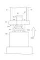
- Figure 6 is a diagram explaining the connection stiffness Ru and the holding stiffness Rd in the vibration suppression state.
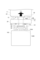
- Figure 7 is a diagram explaining the connection stiffness Ru and the holding stiffness Rd in the sway suppression state.
- the control device 9 controls the pressing force F to a first pressing force F1, as illustrated in FIG. 6, to place the ceiling transport vehicle 1 in a vibration suppression state.
- the traveling state is the first traveling state
- the control device 9 controls the position of the lifting unit 6 to a first position P1, thereby pressing the upper surface of the receiving member 30 against the lower surface of the lifting drive unit 11 with the first pressing force F1.
- the distance L between the lifting drive unit 11 and the lifting platform 20 in the vibration suppression state is referred to as the "first distance L1".
- the compression amount of the first elastic body 31 is the first compression amount
- the compression amount of the second elastic body 54 is the first compression amount. Therefore, the connection stiffness Ru becomes the first connection stiffness Ru1 according to the first compression amount, and the holding stiffness Rd becomes the first holding stiffness Rd1 according to the first compression amount.
- the control device 9 controls the pressing force F to a second pressing force F2 to put the ceiling transport vehicle 1 into a vibration suppression state.
- the second pressing force F2 is greater than the first pressing force F1.
- the control device 9 controls the distance between the lifting drive unit 11 and the lifting platform 20 to a second distance L2 that is narrower than the first distance L1 by gradually changing the position of the lifting unit 6 to a second position P2 that is higher than the first position P1.
- the vibration suppression state shown in FIG. 7 is a state in which the position of the lifting unit 6 is raised from the first position P1 to the second position P2 by winding up the multiple hanging members 12 by a preset amount from the vibration suppression state shown in FIG. 6.
- the compression amount of the first elastic body 31 and the compression amount of the second elastic body 54 become a second compression amount (>first compression amount) that is greater than the first compression amount. Therefore, the connection stiffness Ru becomes a second connection stiffness Ru2 according to the second compression amount, and the second connection stiffness Ru2 in the vibration suppression state is higher than the first connection stiffness Ru1 in the vibration suppression state.
- the holding stiffness Rd becomes a second holding stiffness Rd2 according to the second compression amount, and the second holding stiffness Rd2 in the vibration suppression state is higher than the first holding stiffness Rd1 in the vibration suppression state.
- the state of the ceiling transport vehicle 1 switches to a vibration suppression state
- the state of the ceiling transport vehicle 1 switches to a sway suppression state.
- the ceiling transport vehicle 1 travels with the position of the lifting unit 6 lowered from the second position P2 to the first position P1 so that in the first traveling state, the pressing force F becomes the first pressing force F1 that is weaker than the second pressing force F2 (FIG. 6).
- the ceiling transport vehicle 1 travels or stops with the position of the lifting unit 6 raised from the first position P1 to the second position P2 so that in the second traveling state, the pressing force F becomes the second pressing force F2 that is stronger than the first pressing force F1.
- the pressing force F is changed stepwise from the first pressing force F1 to the second pressing force F2.
- switching from a vibration suppression state to a shaking suppression state, or switching from a shaking suppression state to a vibration suppression state may be performed stepwise rather than discontinuously.
- the vibration and shaking of the container 100 held by the ceiling transport vehicle 1 will be described.
- the vibration of the ceiling transport vehicle 1 may be transmitted to the container 100, causing the container 100 to vibrate.
- the wheels 2a rolling on the ceiling track R may be subjected to an impact at the joint (connection) of the ceiling track R.
- some impact may be applied to the wheels 2a when the ceiling transport vehicle 1 travels over the step.
- the vibrations may be applied to the container 100. For this reason, it is desirable to suppress such vibrations as much as possible.
- the ceiling transport vehicle 1 When the ceiling transport vehicle 1 performs a transfer operation such as moving the container 100 to the side or lowering it at a transfer position on the ceiling track R, the ceiling transport vehicle 1 stops at that transfer position and then starts the transfer operation.
- the container 100 may be swinging significantly in the travel direction or sideways. If the transfer operation to the load port is started while the container 100 is swinging significantly, the container 100 may run up onto the carrier guide on the load port. For this reason, it is possible to wait at the transfer position without starting the transfer operation until the swinging of the container 100 stops, but in that case the transfer time will be longer and the transport capacity will be reduced. Therefore, during the transfer operation, it is desirable to suppress the swinging of the container 100 as much as possible.
- connection stiffness Ru and the holding stiffness Rd are always kept constant regardless of the traveling state by controlling the pressing force F to always be constant.
- the pressing force F is increased to maintain the connection stiffness Ru and the holding stiffness Rd at a high state.
- the shaking of the container 100 during the transfer operation can be suppressed, but the vibration of the container 100 during traveling cannot be suppressed and increases.
- the connection stiffness Ru and the holding stiffness Rd are high, they are easily transmitted to the container 100 via the main body part 4 and the lifting part 6.
- connection stiffness Ru and holding stiffness Rd are set to suppress the shaking of the container 100 during the transfer operation, the vibration of the container 100 during traveling cannot be suppressed.
- a low connection stiffness Ru and holding stiffness Rd are set to suppress the vibration of the container 100 during traveling, the shaking of the container 100 during the transfer operation cannot be suppressed.
- connection stiffness Ru and the holding stiffness Rd are always kept constant regardless of the traveling state, it is possible to suppress only one of the vibration of the container 100 during traveling and the shaking of the container 100 during the transfer operation.
- the ceiling transport vehicle 1 does not always control the pressing force F to be constant, but changes the pressing force F according to the traveling state of the ceiling transport vehicle 1.
- the ceiling transport vehicle 1 changes the connection stiffness Ru and the holding stiffness Rd according to the traveling state of the ceiling transport vehicle 1. For example, when traveling in the first traveling state, the ceiling transport vehicle 1 sets the pressing force F to the first pressing force F1, thereby lowering the connection stiffness Ru and the holding stiffness Rd and establishing a vibration suppression state in which the vibration due to the above-mentioned impact is not easily transmitted to the container 100.
- the ceiling transport vehicle 1 sets the pressing force F to the second pressing force F2 higher than the first pressing force F1, thereby increasing the connection stiffness Ru and the holding stiffness Rd and establishing a vibration suppression state in which the vibration of the container 100 is suppressed. This makes it possible to effectively suppress both the vibration of the container 100 during traveling and the vibration of the container 100 during the transfer operation.
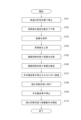
- FIG. 8 is a diagram for explaining an example of the flow of operation of the ceiling transport vehicle 1 according to this embodiment.
- the ceiling transport vehicle 1 travels along the ceiling track R without holding the container 100, and stops at a predetermined position on the ceiling track R (step S101).
- the lifting drive unit 11 lowers the lifting unit 6 to a specified position (step S102), and the pressing unit 52 fits into the recess 100B of the flange 100A, and the holding unit 21 reaches the holding position.
- the holding unit 21 reaches the holding position, the lowering of the lifting unit 6 stops, and the holding unit 21 holds the container 100 (step S103).
- the ceiling transport vehicle 1 raises the lifting unit 6 (step S104).
- the pressing force F is set to the first pressing force F1, thereby setting the connection stiffness Ru to the first connection stiffness Ru1, and the holding stiffness Rd to the first holding stiffness Rd1.
- the control device 9 controls the ceiling transport vehicle 1 to a vibration suppression state by setting the pressing force F to the first pressing force F1 (step S105).
- the first connection stiffness Ru1 and the first holding stiffness Rd1 are adjusted, for example, so that the vibration of the container 100 during travel is within an acceptable range.
- the ceiling transport vehicle 1 travels on the ceiling track R toward the transport position while maintaining the pressing force F at the first pressing force F1 (step S106).
- the control device 9 gradually reduces the speed of the ceiling transport vehicle 1 in order to stop it at the transport position (step S107). Then, when the speed of the ceiling transport vehicle 1 becomes equal to or lower than the second threshold value, the control device 9 changes the pressing force F from the first pressing force F1 to the second pressing force F2.
- the control device 9 changes the pressing force F to the second pressing force F2, thereby transitioning the ceiling transport vehicle 1 from the vibration suppression state to the sway suppression state (step S108).
- the second connection stiffness Ru2 and the second holding stiffness Rd2 are adjusted, for example, so that the sway of the container 100 is within an acceptable range.
- the side-exiting mechanism 8 moves the lifting platform 20 to the side (step S110).
- the pressing force F is maintained at the second pressing force F2 even when the ceiling transport vehicle 1 stops at the transport position. Therefore, the side-exiting mechanism 8 moves the lifting platform 20 to the side in a state in which the connection stiffness Ru is maintained at the second connection stiffness Ru2 and the holding stiffness Rd is maintained at the second holding stiffness Rd2.
- the side-exiting mechanism 8 moves the lifting platform 20 to the side when the ceiling transport vehicle 1 is in a shaking suppression state. This makes it possible to effectively suppress shaking of the container 100 during side-exiting.
- the ceiling transport vehicle 1 does not have to transition to the vibration suppression state in step S105 of FIG. 8.
- the control device 9 may transition the ceiling transport vehicle 1 to the vibration suppression state by setting the pressing force F to the first pressing force F1 when the speed of the ceiling transport vehicle 1 becomes equal to or greater than the first threshold in step S106.
- the control device 9 may control the ceiling transport vehicle 1 to the vibration suppression state when the lifting unit 6 is raised to accommodate the container 100 in the accommodation space AS in step S105.
- the ceiling transport vehicle 1 may then start traveling in the vibration suppression state in step S106, and transition the ceiling transport vehicle 1 from the vibration suppression state to the vibration suppression state by setting the pressing force F to the first pressing force F1 when the speed of the ceiling transport vehicle 1 becomes equal to or greater than the first threshold.
- variable stiffness mechanism 40 in the above-described embodiment includes the first variable stiffness mechanism 22 and the second variable stiffness mechanism 23, but is not limited to this.
- the variable stiffness mechanism 40 may include, for example, either the first variable stiffness mechanism 22 or the second variable stiffness mechanism 23.
- Figure 9 is a diagram showing a first modified example of the variable stiffness mechanism 40.
- the variable stiffness mechanism 40 of the first modified example shown in Figure 9 is the first variable stiffness mechanism 22.
- the stiffness between the main body 4 and the holding part 21 is the connection stiffness Ru.
- the connection stiffness Ru which is the stiffness between the lifting drive part 11 and the lifting platform 20
- the connection stiffness Ru is changed according to the traveling state of the ceiling transport vehicle 1, including when it is stopped.
- the connection stiffness Ru is the first connection stiffness Ru1.
- the connection stiffness Ru is the second connection stiffness Ru2.
- FIG. 10 is a diagram showing a second modified example of the variable stiffness mechanism 40.
- the variable stiffness mechanism 40 of the second modified example shown in FIG. 10 is the second variable stiffness mechanism 23.
- the second variable stiffness mechanism 23 of the second modified example further includes a receiving member 30, as an example.
- the rigidity between the main body 4 and the holding part 21 is the holding rigidity Rd.
- the holding rigidity Rd which is the rigidity between the lift platform 20 and the container 100, is changed according to the traveling state of the ceiling transport vehicle 1, including when it is stopped.
- the holding rigidity Rd is the first holding rigidity Rd1.
- the holding rigidity Rd is the second holding rigidity Rd2.
- the first variable stiffness mechanism 22 and the second variable stiffness mechanism 23 may be independently controllable.
- a first motor that operates the first variable stiffness mechanism 22 and a second motor that operates the second variable stiffness mechanism 23 may be provided, and the control device 9 may operate the first motor to change the coupling stiffness Ru and control the second motor to change the holding stiffness Rd.
- a ceiling transport vehicle 1 that travels along a ceiling track R while holding an article (container 100), A running section 2 that runs along a ceiling track R; A main body 4 that moves along a ceiling track R together with the running part 2; A lift table 20 that is suspended from the main body 4 and can be raised and lowered relative to the main body 4; A holding part 21 that is fixed to the lower part of the lifting platform 20 and holds an article (container 100); a variable stiffness mechanism 40 capable of switching between a first stiffness state (vibration suppression state) in which the stiffness between the main body portion 4 and the holding portion 21 is a first stiffness and a second stiffness state in which the stiffness is a second stiffness higher than the first stiffness; Equipped with The variable stiffness mechanism 40 switches between a first stiffness state (vibration suppression state) and a second stiffness state (sway suppression state) depending on the traveling state of the ceiling transport vehicle 1.
- the variable stiffness mechanism 40 is When the speed of the ceiling transport vehicle 1 is equal to or higher than a first speed, the state is switched to a first rigidity state (vibration suppression state), and when the speed of the ceiling transport vehicle 1 is equal to or lower than a second speed that is slower than the first speed or when the ceiling transport vehicle is stopped, the state is switched to a second rigidity state (sway suppression state).
- the ceiling transport vehicle 1 according to configuration 1.
- the rigidity is either or both of a connection rigidity Ru between the main body 4 and the lift platform 20 and a holding rigidity Rd between the lift platform 20 and the article (container 100) when the holding part 21 is holding the article (container 100).
- the ceiling transport vehicle 1 according to configuration 1 or 2.
- the variable stiffness mechanism 40 includes an elastic body (first elastic body 31) provided between the main body 4 and an upper portion of the lift table 20,
- the main body 4 includes a lift driver 11 that can adjust the compression amount of the elastic body by adjusting the position of the lift platform 20.
- variable stiffness mechanism 40 is A support portion 51 is provided under the lift platform 20 and moves up and down in response to the lift platform 20 being raised and lowered; A pressing portion 52 is provided at the lower portion of the support portion and presses downward the article (container 100) held by the holding portion 21; an elastic body (second elastic body 54) provided between the support portion and the pressing portion; Equipped with The main body 4 includes a lift driver 11 that adjusts the position of the lift platform 20 to adjust the compression amount of the elastic body.
- the ceiling transport vehicle 1 of any one of configurations 1 to 3, wherein the lifting drive unit 11 changes the holding rigidity Rd by changing the compression amount of the elastic body.
- the variable stiffness mechanism 40 is A receiving member 30 provided on the upper part of the lift table 20; a first elastic body 31 provided between the receiving member 30 and an upper portion of the lift table 20; A support portion 51 provided at the lower portion of the lift platform 20; A connecting member 53 that connects the receiving member and the support portion; A pressing portion 52 is provided at the lower portion of the support portion and presses downward the article (container 100) held by the holding portion 21; a second elastic body 54 provided between the support portion and the pressing portion; Equipped with The main body 4 includes a lifting drive unit 11 that adjusts the position of the lifting platform 20 with the receiving member in contact with the main body 4 to adjust the compression amount of the first elastic body 31 and the second elastic body 54; As the compression amount of the first elastic body 31 and the second elastic body 54 increases, the connection rigidity Ru and the retention rigidity Rd increase.
- the main body 4 includes a lateral movement mechanism 8 for moving the lift platform 20 laterally in the traveling direction.
- the lateral movement mechanism 8 moves the lift platform 20 laterally when the lift platform 20 is in the second rigid state.
Landscapes
- Engineering & Computer Science (AREA)
- Mechanical Engineering (AREA)
- Carriers, Traveling Bodies, And Overhead Traveling Cranes (AREA)
- Container, Conveyance, Adherence, Positioning, Of Wafer (AREA)
Abstract
【課題】物品の振動及び揺れを抑制する天井搬送車を提供する。 【解決手段】物品(容器100)を保持しながら天井軌道に沿って走行する天井搬送車1であって、天井軌道に沿って走行する走行部と、走行部と共に天井軌道に沿って移動する本体部4と、本体部4に吊り下げられ、本体部4に対して昇降可能である昇降体20と、昇降体20の下部に固定され、物品(容器100)を保持する保持部21と、本体部4と保持部21との間の剛性が第1剛性である第1剛性状態と、剛性が第1剛性よりも高い第2剛性である第2剛性状態とを切り替え可能な可変剛性機構40と、を備え、可変剛性機構40は、天井搬送車1の走行状態に応じて第1剛性状態と第2剛性状態とを切り替える。
Description
本発明は、天井搬送車に関する。
物品を保持しながら天井軌道に沿って走行する天井搬送車が開示されている(例えば、特許文献1参照)。この天井搬送車は、物品を移載先に運ぶ場合には、物品を保持しながら天井軌道に沿って走行して所定の搬送位置まで搬送する。そして、天井搬送車は、搬送位置で物品を横出ししたり下げたりするなどの移載動作を行い、移載先への物品の移載を行う。
天井搬送車では、保持している物品の振動及び揺れを抑制することは、搬送能力や移載能力を向上させる点から重要である。
本発明は、物品の振動及び揺れを抑制する天井搬送車を提供することを目的とする。
本発明の態様に係る天井搬送車は、物品を保持しながら天井軌道に沿って走行する天井搬送車であって、天井軌道に沿って走行する走行部と、走行部と共に天井軌道に沿って移動する本体部と、本体部に吊り下げられ、本体部に対して昇降可能である昇降体と、昇降体の下部に固定され、物品を保持する保持部と、本体部と保持部との間の剛性が第1剛性である第1剛性状態と、剛性が第1剛性よりも高い第2剛性である第2剛性状態とを切り替え可能な可変剛性機構と、を備え、可変剛性機構は、天井搬送車の走行状態に応じて第1剛性状態と第2剛性状態とを切り替える。
本発明の態様に係る天井搬送車は、本体部と保持部との間の剛性が天井搬送車の停止を含む走行状態に応じて切り替わることで、物品への振動が伝わることを抑制したり、物品が揺れにくくしたりすることができ、天井走行車の状態に応じて物品の振動及び揺れを抑制することができる。
上記態様に係る天井搬送車によれば、可変剛性機構は、天井搬送車の速度が第1速度以上の場合には第1剛性状態に切り替え、天井搬送車の速度が第1速度よりも遅い第2速度以下の場合又は天井搬送車が停止している場合には第2剛性状態に切り替えてもよい。このような構成によれば、走行時の物品への振動及び移載時の物品の揺れを効果的に抑制することができる。
上記態様に係る天井搬送車によれば、本体部と保持部との間の剛性は、保持部が物品を保持している状態において、本体部と昇降体の間の剛性である連結剛性と、昇降体と物品との間の剛性である保持剛性とのいずれか又は両方であってもよい。このような構成によれば、走行時の物品への振動及び移載時の物品の揺れを効果的に抑制することができる。
上記態様に係る天井搬送車によれば、可変剛性機構は、本体部と昇降体の上部との間に設けられた弾性体を備え、本体部は、昇降体の位置を調整することで弾性体の圧縮量を調整可能な昇降駆動部を備え、昇降駆動部は、弾性体の圧縮量を変更することで連結剛性を変更してもよい。このような構成によれば、走行時の物品への振動及び移載時の物品の揺れを効果的に抑制することができる。
上記態様に係る天井搬送車によれば、可変剛性機構は、昇降体の下部に設けられ、昇降体の昇降動作に応じて上下方向に移動する支持部と、支持部の下部に設けられ、保持部が保持している物品を下向きに押圧する押圧部と、支持部と押圧部との間に設けられた弾性体と、を備え、本体部は、昇降体の位置を調整することで弾性体の圧縮量を調整する昇降駆動部を備え、昇降駆動部は、弾性体の圧縮量を変更することで保持剛性を変更してもよい。このような構成によれば、走行時の物品への振動及び移載時の物品の揺れを効果的に抑制することができる。
上記態様に係る天井搬送車によれば、可変剛性機構は、昇降体の上部に設けられた受け部材と、受け部材と昇降体の上部との間に設けられた第1弾性体と、昇降体の下部に設けられた支持部と、受け部材と支持部とを連結する連結部材と、支持部の下部に設けられ、保持部が保持している物品を下向きに押圧する押圧部と、支持部と押圧部との間に設けられた第2弾性体と、を備え、本体部は、受け部材を本体部に接触させた状態で昇降体の位置を調整することで第1弾性体及び第2弾性体の圧縮量を調整する昇降駆動部を備え、第1弾性体及び第2弾性体の圧縮量が大きくなるほど連結剛性及び保持剛性が高くなり、第1剛性状態の場合には、第1弾性体及び第2弾性体の圧縮量が第1圧縮量に制御され、第2剛性状態の場合には第1弾性体及び第2弾性体の圧縮量が第1圧縮量よりも大きい第2圧縮量に制御されてもよい。このような構成によれば、走行時の物品への振動及び移載時の物品の揺れをより効果的に抑制することができる。
上記態様に係る天井搬送車によれば、本体部は、昇降体を走行方向の側方に移動させる横出し機構を備え、横出し機構は、第2剛性状態である場合に昇降体を側方に移動させてもよい。このような構成によれば、移載時の物品の揺れを抑制することができる。
以下、実施形態を通じて本発明を説明するが、以下の実施形態は特許請求の範囲にかかる発明を限定されない。また、実施形態の中で説明されている特徴の組み合わせの全てが発明の解決手段に必須であるとは限らない。なお、図面において、同一又は類似の部分には同一の符号を付して、重複する説明を省く場合がある。また、図面における要素の形状及び大きさなどはより明確な説明のために誇張されるなど、実際の製品とは、形状、寸法が異なる場合がある。
図面において、XYZ座標系を用いて図中の方向を説明する場合がある。XYZ座標系においては、水平面に平行な平面をXY平面とする。このXY平面における一方向をX方向と表記し、X方向に直交する方向をY方向と表記する。また、XY平面に垂直な方向はZ方向と表記する。X方向、Y方向及びZ方向のそれぞれは、図中の矢印の指す方向が+方向であり、矢印の指す方向とは反対の方向が-方向であるとして説明する。
図1は、本実施形態に係る天井搬送車を概念的に示す図である。図1には、本実施形態に係る天井搬送車1を-Y方向側から見た図を概念的に示した。
天井搬送車1は、クリーンルームの天井などの床面より高い位置に設けられる天井軌道Rに沿って走行し、容器100を収容空間AS内で吊り下げた状態で搬送する。天井搬送車1は、例えば、処理装置と容器保管装置との間、あるいは2つの処理装置の間などにおいて、容器100の搬送に用いられる。なお、図1におけるX方向は、天井搬送車1の走行方向である。また、図1におけるZ方向は、天井搬送車1の鉛直方向である。
天井搬送車1は、例えば、処理装置と容器保管装置との間、あるいは2つの処理装置の間などにおいて、容器100の搬送に用いられる。処理装置は、例えば、成膜装置、コーター・ディベロッパ、露光装置、エッチング装置などであり、デバイス(例、半導体デバイス)を製造する過程で各種処理を施す。上記容器保管装置は、例えば、容器100を搬送する搬送経路に配置され、容器100を一時的に保管する。上記容器保管装置は、例えば、天井の近傍に配置される。容器100は、例えば、半導体素子の製造に用いられるウエハ又はレチクルなどを収容する。容器100は、例えば、内部をパージ可能なFOUP(Front Opening Unified Pod)、SMIF Pod、又はレチクルPodである。なお、容器100は、本発明の「物品」の一例である。
天井搬送車1は、例えば、走行部2と、連結部3aと、支持部3bと、本体部4と、カバー5a,カバー5bと、昇降部6と、制御装置9を備える。
走行部2は、車輪2aと、走行駆動部2bとを備える。車輪2aは、天井軌道Rに接するように配置され、走行駆動部2bの駆動力により回転駆動する。走行駆動部2bは、天井搬送車1を走行させるための駆動力を発生させる。走行駆動部2bは、例えば、リニアモータ又は回転モータなどの走行モータを有する。また、走行駆動部2bは、ロータリーエンコーダ又はリニアエンコーダを有する。走行駆動部2bは、ロータリーエンコーダ又はリニアエンコーダにより検出された車輪2aの回転数などの検出結果に基づいてリニアモータ又は回転モータを制御し、天井搬送車1の速度あるいは停止位置を行う。
連結部3aは、走行駆動部2bと支持部3bとを連結する。例えば、連結部3aは、一端が走行駆動部2bに接続されており、他端が支持部3bに接続されている。支持部3bは、水平面に沿って配置され、本体部4を支持する。
本体部4は、連結部3aを介して走行駆動部2bに連結されており、走行部2と共に天井軌道に沿って移動する。本体部4は、例えば、昇降装置7と、横出し機構8とを備える。昇降装置7は、昇降駆動部11と、吊り下げ部材12とを備える。
昇降装置7は、所定の速度で昇降部6を降下又は上昇させたり、昇降部6を目標の高さに保持したりする。昇降部6は、本体部4から複数の吊り下げ部材12によって吊り下げられている。昇降駆動部11は、例えばホイストであって、複数の吊り下げ部材12を繰り出すことにより昇降部6を下降させる。また、昇降駆動部11は、複数の吊り下げ部材12を巻き取ることにより昇降部6を上昇させる。
例えば、昇降駆動部11は、例えば、1つ以上の回転体110と、昇降モータ120とを備える。回転体110は、例えば外周に吊り下げ部材12のための巻取り面を有する円筒形状のドラムである。昇降モータ120は、回転体110を回転駆動して複数の吊り下げ部材12の巻き取り及び繰り出し(巻下げ)を行う電動モータである。なお、昇降駆動部11は、例えば、複数の吊り下げ部材12を支持するプーリなどのローラを有してもよい。吊り下げ部材12を用いて昇降部6を吊り下げている場合には、昇降駆動部11は、吊り下げ部材12を巻き取ったり、繰り出したりする構成を有していればよく、回転体110及び昇降モータ120を必ず有している必要はない。
吊り下げ部材12は、一端が昇降駆動部11に接続され、他端が昇降部6に接続されている。吊り下げ部材12は、例えば、ベルトである。本実施形態では、昇降部6は、例えば、3つ又は4つの吊り下げ部材12によって本体部4から吊り下げられている。ただし、吊り下げ部材12の数には特に限定されず、複数であればよい。例えば、吊り下げ部材12内には、ケーブルなどの導電部材が設けられており、この導電部材を介して本体部4から電力が昇降部6に供給される。
横出し機構8は、昇降駆動部11を本体部4の走行方向に対する左右方向に横出しする横出し動作を行う。本体部4の走行方向は、走行部2によって天井搬送車1が天井軌道Rに沿って走行する方向、すなわちX方向である。左右方向は、走行方向に直交する方向、すなわちY方向である。この左右方向は、横出し機構8が昇降駆動部11を横出しする方向であり、以下、横出し方向Dと称する。
横出し機構8は、例えば、ベース部13と、1つ以上のスライド部14とを備える。なお、図1及び図2に例示する横出し機構8は、2つのスライド部14を有している。なお、一方のスライド部14を「第1スライド部14A」と称し、他方のスライド部14を「第2スライド部14B」と称する。
ベース部13は、連結部3aの下方に取り付けられている。ベース部13は、例えば、支持部3bに取り付けられている。ベース部13は、例えば板状の部材である。ベース部13は、ベース部13の平面が水平方向と平行になるように配置されている。
第1スライド部14Aは、ベース部13の下面側に配置されている。第1スライド部14Aは、例えば板状の部材であって、Z方向において平面がベース部13の平面と平行になるように配置されている。第1スライド部14Aは、例えば、ベース部13と同等の形状を有する。第1スライド部14Aは、ベース部13に対して横出し方向に移動可能である。
第2スライド部14Bは、第1スライド部14Aの下面側に配置されている。第2スライド部14Bは、例えば板状の部材であって、Z方向において平面がベース部13の平面及び第1スライド部14Aの平面に対して平行になるように配置されている。第2スライド部14Bは、例えば、第1スライド部14Aと同等の形状を有する。第2スライド部14Bの下面には昇降駆動部11が設けられる。第2スライド部14Bは、第1スライド部14Aに対して横出し方向に移動可能である。横出し機構8は、例えば、電動モータ等の不図示の駆動部を有し、この駆動部からの駆動力によって、第1スライド部14Aをベース部13に対して横出し方向Dに横出しするとともに、第1スライド部14Aの横出しに連動させて、第2スライド部14Bを第1スライド部14Aに対して同じ横出し方向Dに横出しする。なお、横出し機構8は、昇降駆動部11を横出し方向Dに横出しできる構成を有していればよく、ベース部13及び1つ以上のスライド部14以外の構成を採用してもよい。
本体部4の-X側の側方にはカバー5aが設けられており、+X側の側方にはカバー5bが設けられている。カバー5a及びカバー5bは、それぞれ、支持部3bに固定されており、その支持部3bから-Z方向に向けて延びて配置される。一対のカバー5a,5bは、容器100が収容される空間、すなわち収容空間ASを形成する。
昇降部6は、昇降台20と、保持部21と、可変剛性機構40とを備える。なお、昇降台20は、昇降体の一例である。昇降体は、昇降台20に限定されず、本体部4に対して昇降可能であればよい。
昇降台20には、複数の吊り下げ部材12の他端が固定されている。昇降台20は、例えば、板状部材であって、平面が水平面と平行になるように、複数の吊り下げ部材12によって吊り下げられている。ただし、本実施形態において、昇降台20の形状には特に限定されない。
保持部21は、昇降台20の下面に固定されている。保持部21は、容器100を保持する。保持部21が、例えば、容器100のフランジ100Aを把持することにより、容器100を吊り下げて保持する。なお、保持部21が容器100を把持する方法は、特に限定されないが、上から容器100を把持してもよいし、左右から挟み込むことで容器100を把持してもよい。保持部21は、例えば、水平方向に移動可能な複数の爪部21aを備えるチャックである。保持部21は、モータなどの駆動力により、爪部21aをフランジ100Aの下方に移動させる。そして、昇降駆動部11による吊り下げ部材12の巻き上げによって保持部21が上昇することで、保持部21は、容器100を吊り下げた状態で保持する。
可変剛性機構40は、保持部21が容器100を収容空間AS内で保持している状態において、本体部4と保持部21との間の剛性が第1剛性である第1剛性状態と、当該剛性が第1剛性よりも高い第2剛性である第2剛性状態とを切り替え可能である。可変剛性機構40は、第1可変剛性機構22及び第2可変剛性機構23を有する。図1に示す可変剛性機構において、本体部4と保持部21との間の剛性とは、本体部4と昇降台20との間の連結剛性Ruと、昇降台20と容器100のフランジ100Aとの間の保持剛性Rdとの両方である。
第1可変剛性機構22は、保持部21が容器100を保持している状態において、本体部4と昇降台20との間の連結剛性Ruを調整可能な機構を有する。第1可変剛性機構22は、例えば、昇降台20の上面側に設けられる。第1可変剛性機構22は、例えば、受け部材30と、第1弾性体31とを備える。
受け部材30は、昇降台20の上部に設けられている。受け部材30は、上面において、昇降駆動部11の下面を受ける。具体的には、天井搬送車1が収容空間AS内に容器100を収容した際に、受け部材30の上面が昇降駆動部11の下面に接触する。受け部材30は、例えば、板状部材であって、平面(上面及び下面)が水平面と平行になるように配置されている。
第1弾性体31は、受け部材30の下面と昇降台20の上面との間に設けられている。第1弾性体31は、例えば、ゲル材、ゴム材、及び圧縮ばねの1つ以上を含む。第1弾性体31は、上端が受け部材30に接しており、下端が昇降台20の上面に接している。
第2可変剛性機構23は、保持部21が容器100を保持している状態において、昇降台20と容器100のフランジ100Aとの間の保持剛性Rdを調整可能な機構を有する。第2可変剛性機構23は、例えば、支持部51と、押圧部52と、連結部材53と、第2弾性体54とを備える。
支持部51は、昇降台20の下部に設けられている。支持部51は、平面が水平面と平行になるように配置されている。
押圧部52は、支持部51の下部に設けられ、保持部21が保持している容器100を下向きに押圧する。押圧部52は、例えば、容器100に対する保持部21の位置決めのために、保持部21によって保持されている容器100のフランジ100Aに形成された凹部100Bに嵌合する部材である。
連結部材53は、受け部材30と支持部51とを連結する。連結部材53は、例えば、上下方向に延びた部材であって、一端が受け部材30に固定され、他端が支持部51に固定されている。連結部材53は、昇降台20に対して上下方向に移動可能である。従って、支持部51も昇降台20に対して上下方向に移動可能である。例えば、受け部材30が下方向に移動すると、連結部材53も下方向に移動する。そのため、連結部材53の他端に固定されている支持部51も昇降台20に対して下方向に移動する。
第2弾性体54は、支持部51と押圧部52との間に設けられている。すなわち、第2弾性体54は、一端が支持部51に接続され、他端が押圧部52に接続されている。第2弾性体54は、押圧部52を下方向に付勢する。第2弾性体54は、例えば、ゲル材、ゴム材、及び圧縮ばねの1つ以上を含む。
制御装置9は、CPU(Central Processing Unit)又はMPU(Micro Processing Unit)などのプロセッサ及び不揮発性又は揮発性の半導体メモリ(例えば、RAM(Random Access Memory)、ROM(Read Only Memory)、フラッシュメモリ、EPROM(Erasable Programmable Read Only Memory)、EEPROM(Electrically Erasable Programmable Read Only Memory))を備えてもよい。例えば、制御装置9は、MCUなどのマイクロコントローラであってもよい。
制御装置9は、天井搬送車1の各種動作を制御する。制御装置9は、走行駆動部2bを制御することで、天井搬送車1の走行を制御する。制御装置9は、横出し機構8に設けられた駆動部(例えば、電動モータ)を制御することで、横出し機構8による横出し動作を制御する。
制御装置9は、昇降駆動部11を制御する。例えば、制御装置9は、昇降モータ120の回転を制御することで、吊り下げ部材12の巻き取り及び繰り出し(巻下げ)を制御する。換言すれば、制御装置9は、昇降モータ120の回転を制御することで昇降部6のZ方向における位置(以下、「昇降部6の位置」という。)を制御することができる。図2は、本実施形態に係る天井搬送車の横移載を模式的に示した図である。横移載とは、横出し動作後に吊り下げ部材12を繰り出すことで容器100を所定の位置に移載することである。天井搬送車1は、例えば、容器100を収容空間ASに収容した状態で天井軌道R上の所定位置(以下、「搬送位置」という。)まで走行し、その搬送位置で横移載を行う。
制御装置9は、保持部21が収容空間AS内で容器100を保持している状態において、昇降モータ120の回転を制御して昇降部6の位置を変更させることで第1可変剛性機構22及び第2可変剛性機構23を動作させる。これにより、制御装置9は、連結剛性Ruと保持剛性Rdとの両方を調整することができる。すなわち、制御装置9は、保持部21で容器100を保持しながら受け部材30の上面が昇降駆動部11の下面に接触している状態において、昇降部6の位置を調整することで連結剛性Ru及び保持剛性Rdの両方を調整することができる。
制御装置9は、天井搬送車1の走行状態に応じて、連結剛性Ruと保持剛性Rdとの両方を変更する。走行状態とは、例えば、容器100を収容した天井搬送車1の走行の開始、天井搬送車1の速度が第1閾値以上である状態(以下、「第1走行状態」という。)、容器100を収容した天井搬送車1の停止動作の開始、天井搬送車1の速度が第2閾値未満である状態(以下、「第2走行状態」という。)、天井搬送車1が停止している状態(以下、「停止状態」という。)の少なくとも1つ以上を含む。なお、第2閾値は、ヒステリシスの形成のため、第1閾値よりも小さいが、第1閾値と同じ値であってもよい。
第2走行状態は、容器100を保持しながら天井軌道Rに沿って走行している天井搬送車1が停止するために減速した場合であって、減速している天井搬送車1の速度が第1閾値よりも遅い第2閾値未満となった状態であってもよい。第2走行状態は、天井搬送車1が走行を開始してから天井搬送車1の速度が第2閾値以上となるまでの状態を含まなくてもよいし、当該状態を含んでもよい。
制御装置9は、例えば、現在の天井搬送車1の走行状態が第1走行状態及び第2走行状態のいずれかであるかを判定してもよい。制御装置9は、例えば、速度センサなどで天井搬送車1の速度を直接的に計測することで現在の天井搬送車1の走行状態が第1走行状態及び第2走行状態のいずれかであるかを判定してもよい。制御装置9は、例えば、走行駆動部2bの回転数や走行駆動部2bに供給する電圧などの値を計測することで天井搬送車1の速度を間接的に取得して現在の天井搬送車1の走行状態が第1走行状態及び第2走行状態のいずれかであるかを判定してもよい。
また、第1閾値以上の速度で走行する区間(以下、「第1区間」という。)と、第2閾値未満の速度で走行する区間(以下、「第2区間」という。)と、停止する区間(以下、「第3区間」という。)とが予め設定されており、制御装置9は、現在の天井搬送車1の位置が第1区間、第2区間及び第3区間のどの区間であるかを判別することで、天井搬送車1の走行状態が第1走行状態及び第2走行状態のいずれかであるかを判定してもよい。ただし、本実施形態では、天井搬送車1の走行状態が第1走行状態及び第2走行状態のいずれかであるかを直接的又は間接的に判定できればよく、その判定方法に関しては特に限定されない。また、制御装置9は、上記速度センサのセンサ結果や走行駆動部2bの回転数や走行駆動部2bに供給する電圧などの値に基づいて現在の天井搬送車1が停止状態であるか否かを判定してもよいし、天井搬送車1の位置が第3区間であることを検知した場合に現在の天井搬送車1が停止状態であると判定してもよい。
制御装置9は、例えば第1可変剛性機構22によって定まる連結剛性Ruと第2可変剛性機構23によって定まる保持剛性Rdとの両方が、第1走行状態の場合よりも第2走行状態の場合又は天井搬送車1が停止している場合の方が高くなるように昇降部6の位置を制御する。例えば、制御装置9は、天井搬送車1の走行状態が第1走行状態である場合には、昇降部6の位置を第1位置P1(例えば、図6参照)とすることで、連結剛性Ruを第1連結剛性Ru1に制御し、保持剛性Rdを第1保持剛性Rd1に制御する。連結剛性Ruが第1連結剛性Ru1に制御され、保持剛性Rdが第1保持剛性Rd1に制御されている状態を「振動抑制状態」と称する場合がある。振動抑制状態とは、走行中における容器100に振動を抑制する状態である。振動抑制状態は、第1剛性状態の一例である。
天井搬送車1の走行状態が第2走行状態である場合又は天井搬送車1が停止している場合には、昇降部6の位置を第1位置P1よりも高い第2位置P2(例えば、図7参照)とすることで、連結剛性Ruを第1連結剛性Ru1よりも高い第2連結剛性Ru2とし、保持剛性Rdを第1保持剛性Rd1よりも高い第2保持剛性Rd2とする。連結剛性Ruが第2連結剛性Ru2に制御され、保持剛性Rdが第2保持剛性Rd2に制御されている状態を「揺れ抑制状態」と称する場合がある。揺れ抑制状態とは、容器100の揺れを抑制する状態である。なお、昇降部6の位置が第1位置P1及び第2位置P2のそれぞれの場合において、受け部材30の上面が昇降駆動部11の下面に接触している。揺れ抑制状態は、第2剛性状態の一例である。
以下に、天井搬送車1の保持動作を説明する。図3に示す天井搬送車1は、容器100を保持していない状態(以下、「初期状態」という。)を示す図である。図3に示す初期状態では、保持部21が容器100を保持しておらず、受け部材30の上面が昇降駆動部11の下面に接触していない。図4は、天井搬送車1が容器100を保持している状態を示す図である。
天井搬送車1が初期状態である場合において、昇降駆動部11は、制御装置9の制御によって、吊り下げ部材12を繰り出して昇降部6を下降させる。昇降部6が下降していくと、図4に示すように、フランジ100Aの凹部100Bに押圧部52が嵌合し、自重で下降する保持部21に対して押圧部52が相対的に上昇する。押圧部52が相対的に所定位置まで上昇すると、保持部21が保持位置に到達したとして、昇降駆動部11は、昇降部6の下降を停止する。
昇降部6の下降が停止すると、保持部21は、制御装置9からの指示に基づいて、爪部21aをフランジ100Aの下方に移動させることにより、容器100を保持する。保持部21が容器100を保持すると、昇降駆動部11は、制御装置9からの制御により、複数の吊り下げ部材12を巻き取ることにより昇降部6を上昇させる。容器100を収容空間ASに収容する。以下、容器100が収容空間ASに収容されている状態を「収容状態」と称する場合がある。
図5は、本実施形態に係る収容状態の一例を示す図である。収容状態では、受け部材30の上面が昇降駆動部11の下面に接触している。受け部材30の上面が昇降駆動部11の下面に接触すると、第1可変剛性機構22が動作して本体部4と昇降台20との間の連結剛性Ruが高くなる。具体的には、受け部材30の上面が昇降駆動部11の下面に押し付けられると第1弾性体31が圧縮され、その圧縮量に応じた上下方向の弾性力が発生する。換言すれば、昇降部6を昇降駆動部11(本体部4)に押し付けることで第1弾性体31が圧縮され、その圧縮量に応じた上下方向の弾性力が発生する。第1弾性体31は、この弾性力によって受け部材30を上方向に付勢し、昇降台20を下方向に付勢する。なお、第1弾性体31の圧縮量とは、例えば、受け部材30の上面が昇降駆動部11の下面に押し付けられたことで変化した第1弾性体31の長さであってもよい。
このように、昇降駆動部11と昇降台20とに挟持された第1弾性体31が圧縮されると、その圧縮量に応じた弾性力が発生して昇降駆動部11と昇降台20との間の連結剛性Ruが高まる。なお、第1弾性体31の圧縮量が大きいほど連結剛性Ruが高い。なお、第1弾性体31の圧縮量は、昇降駆動部11と昇降台20との間の距離Lに応じて変動する。すなわち、昇降台20が上方向に移動して昇降駆動部11と昇降台20との間の距離Lが短くなるにつれて第1弾性体31の圧縮量が大きくなる。したがって、天井搬送車1は、昇降駆動部11と昇降台20との間の距離Lを変更することで、第1弾性体31の圧縮量を変更することでき、結果として連結剛性Ruを変更することができる。
受け部材30の上面が昇降駆動部11の下面に押し付けられて第1弾性体31が圧縮すると、昇降台20が上向きに移動する。すなわち、第1弾性体31が圧縮すると、第2可変剛性機構23が動作して支持部51に対して押圧部52が相対的に上向きに変位する。このため、第2弾性体54が圧縮され、昇降台20と容器100のフランジ100Aとの間の保持剛性Rdが高くなる。具体的には、第2弾性体54の圧縮量に応じた上下方向の弾性力が発生する。第2弾性体54は、第2弾性体54の圧縮量に応じた弾性力で押圧部52をフランジ100Aに押し付ける。
このように、昇降台20と容器100とに挟持された第2弾性体54が圧縮されると、その圧縮量に応じた弾性力が発生して押圧部52をフランジ100Aに押し付ける。これにより、昇降台20と容器100のフランジ100Aとの間の保持剛性Rdが高まる。なお、第2弾性体54の圧縮量が大きいほど保持剛性Rdが高い。
第2弾性体54の圧縮量は、支持部51と押圧部52との間の距離に応じて変動する。そして、図5に示す例では、支持部51と押圧部52との間の距離は、昇降駆動部11と昇降台20との間の距離Lに応じて変動する。そのため、第2弾性体54の圧縮量は、第1弾性体31の圧縮量と同様に、昇降駆動部11と昇降台20との間の距離Lに応じて変動する。換言すれば、昇降部6を昇降駆動部11(本体部4)に押し付けることで第1弾性体31だけでなく第2弾性体54も圧縮される。
昇降台20が上方向に移動して昇降駆動部11と昇降台20との間の距離Lが短くなるにつれて第2弾性体54の圧縮量が大きくなる。したがって、天井搬送車1は、昇降駆動部11と昇降台20との間の距離Lを変更することで第2弾性体54の圧縮量も変更することでき、結果として保持剛性Rdを変更することができる。ここで、図5に例示する構成では、昇降駆動部11と昇降台20との間の距離Lを変更することは、昇降部6を昇降駆動部11(本体部4)に押し付ける力である押し付け力Fが変更することと同義である。したがって、天井搬送車1は、押し付け力Fを変更することで第1弾性体31の圧縮量及び第2弾性体54の圧縮量を変更することでき、結果として連結剛性Ru及び保持剛性Rdを変更することができる。
以下に、連結剛性Ru及び保持剛性Rdの制御方法について説明する。図6は、振動抑制状態での連結剛性Ru及び保持剛性Rdを説明する図である。図7は、揺れ抑制状態での連結剛性Ru及び保持剛性Rdを説明する図である。
制御装置9は、容器100が収容状態である場合において、天井搬送車の速度が第1閾値以上である第1走行状態の場合には、図6に例示するように、押し付け力Fを第1押し付け力F1に制御することで天井搬送車1を振動抑制状態にする。具体的には、制御装置9は、走行状態が第1走行状態の場合には、昇降部6の位置を第1位置P1に制御することで、第1押し付け力F1で受け部材30の上面を昇降駆動部11の下面に押し付ける。振動抑制状態での昇降駆動部11と昇降台20との間の距離Lを「第1距離L1」と称する。振動抑制状態の場合には、第1弾性体31の圧縮量が第1圧縮量及び第2弾性体54の圧縮量が第1圧縮量となる。そのため、連結剛性Ruが第1圧縮量に応じた第1連結剛性Ru1となり、保持剛性Rdが第1圧縮量に応じた第1保持剛性Rd1となる。
制御装置9は、容器100が収容状態である場合において、天井搬送車1の速度が第1閾値よりも遅い第2閾値未満の場合である第2走行状態の場合には、押し付け力Fを第2押し付け力F2に制御することで天井搬送車1を揺れ抑制状態にする。第2押し付け力F2は、第1押し付け力F1よりも大きい。
具体的には、制御装置9は、天井搬送車1が第2走行状態の場合には、昇降部6の位置を第1位置P1よりも高い位置である第2位置P2に段階的に変更することで、昇降駆動部11と昇降台20との間の距離を第1距離L1も狭い第2距離L2に制御する。図7に示す揺れ抑制状態は、図6に示す振動抑制状態から複数の吊り下げ部材12を予め設定された分だけ巻き取ることで昇降部6の位置を第1位置P1から第2位置P2に上昇させた状態である。
揺れ抑制状態の場合には、第1弾性体31の圧縮量及び第2弾性体54の圧縮量が第1圧縮量よりも大きい第2圧縮量(>第1圧縮量)となる。そのため、連結剛性Ruが第2圧縮量に応じた第2連結剛性Ru2となり、揺れ抑制状態での第2連結剛性Ru2は、振動抑制状態での第1連結剛性Ru1よりも高くなる。また、保持剛性Rdが第2圧縮量に応じた第2保持剛性Rd2となり、揺れ抑制状態での第2保持剛性Rd2は、振動抑制状態での第1保持剛性Rd1よりも高くなる。
このように、第1走行状態では、天井搬送車1の状態が振動抑制状態に切り替わり、第2走行状態では天井搬送車1の状態が揺れ抑制状態に切り替わる。具体的には、天井搬送車1は、第1走行状態では押し付け力Fが第2押し付け力F2よりも弱い第1押し付け力F1となるように、昇降部6の位置を第2位置P2から第1位置P1に下げた状態で走行する(図6)。また、天井搬送車1は、第2走行状態では押し付け力Fが第1押し付け力F1よりも強い第2押し付け力F2となるように、昇降部6の位置を第1位置P1から第2位置P2に上げた状態で走行又は停止する。例えば、振動抑制状態から揺れ抑制状態へ切り替えられる場合には、押し付け力Fは、第1押し付け力F1から第2押し付け力F2に段階的に変更される。つまり、振動抑制状態から揺れ抑制状態へ切り替え、又は揺れ抑制状態から振動抑制状態への切り替えは、非連続的ではなく段階的に行われてもよい。
以下に、天井搬送車1が保持している容器100の振動や揺れについて説明する。天井搬送車1が容器100を収容空間ASに収納した状態で天井軌道Rに沿って走行している場合に、天井搬送車1の振動が容器100に伝わってしまい容器100が振動してしまう場合がある。例えば、天井搬送車1が走行する際、天井軌道R上を転動する車輪2aに対し、天井軌道Rの継ぎ目(接続)部分等において衝撃が加わる場合がある。例えば、天井軌道Rの継ぎ目に段差がある場合には、その段差を天井搬送車1が走行すると車輪2aに多少の衝撃が加わり得る。車輪2aに衝撃が加わると、天井搬送車1全体にその衝撃による振動が生じ、結果として容器100にその振動が加わり得る。このため、当該振動をなるべく抑制することが望まれる。
天井搬送車1が容器100を横出ししたり下げたりするなどの移載動作を天井軌道R上の搬送位置で行う場合には、天井搬送車1は、その搬送位置で停止してから移載動作を開始する。ここで、移載動作時において、容器100が走行方向や横方向に大きく揺れている場合がある。容器100が大きく揺れている状態でロードポートへの移載動作が開始されると、容器100がロードポート上のキャリアガイドに乗り上げてしまう場合が起こり得る。そのため、容器100の揺れが収まるまで移載動作を開始せずに搬送位置で待機することも可能だが、その場合は移載時間が長くなり搬送能力が低下してしまう。したがって、移載動作時においては、容器100の揺れをなるべく抑制することが望まれる。
ここで、押し付け力Fを常に一定のままに制御することで、走行状態にかかわらず連結剛性Ru及び保持剛性Rdを常に一定に維持する場合を考える。例えば、移載動作時における容器100の揺れを抑制するために、押し付け力Fを強くして連結剛性Ru及び保持剛性Rdを高い状態のままで維持する。この場合には、移載動作時における容器100の揺れは抑制できるが、走行時での容器100の振動は抑制できずに増大してしまう。具体的には、連結剛性Ru及び保持剛性Rdが高いと、本体部4から昇降部6を介して容器100に伝わり易い。つまり、移載動作時における容器100の揺れを抑制するために高い連結剛性Ru及び保持剛性Rdを設定してしまうと、走行時での容器100の振動は抑制することができない。一方、走行時での容器100の振動を抑制するために低い連結剛性Ru及び保持剛性Rdを設定してしまうと、移載動作時における容器100の揺れを抑制することができない。
このように、走行状態にかかわらず連結剛性Ru及び保持剛性Rdを常に一定に維持すると、走行時での容器100の振動と、移載動作時における容器100の揺れとの一方しか抑制することができない。
本実施形態の一例の構成では、天井搬送車1は、押し付け力Fを常に一定のままに制御するのではなく、押し付け力Fを天井搬送車1の走行状態に応じて変更する。換言すれば、天井搬送車1は、連結剛性Ru及び保持剛性Rdを天井搬送車1の走行状態に応じて変更する。例えば、天井搬送車1は、第1走行状態での走行時においては押し付け力Fを第1押し付け力F1とすることで連結剛性Ru及び保持剛性Rdを低くして上記の衝撃による振動が容器100に伝わりにくい振動抑制状態とする。一方、天井搬送車1は、停止動作が開始した場合や走行が停止した場合においては、押し付け力Fを第1押し付け力F1よりも高い第2押し付け力F2として連結剛性Ru及び保持剛性Rdを高くして容器100の揺れが抑制される揺れ抑制状態とする。これにより、走行時での容器100の振動及び移載動作時の容器100の揺れの双方を効果的に抑制することができる。
以下に、本実施形態に係る天井搬送車1の動作の流れの一例を説明する。図8は、本実施形態に係る天井搬送車1の動作の流れの一例を説明する図である。まず、天井搬送車1は、容器100を保持していない状態で天井軌道Rに沿って走行し、天井軌道Rの所定位置で停止する(ステップS101)。天井搬送車1は、天井軌道Rの所定位置において、昇降駆動部11により昇降部6を規定位置まで下降させていくと(ステップS102)、フランジ100Aの凹部100Bに押圧部52が嵌合し、保持部21が保持位置に到達する。保持部21が保持位置に到達すると昇降部6の下降が停止し、保持部21は、容器100を保持する(ステップS103)。保持部21が容器100を保持すると、天井搬送車1は、昇降部6を上昇させる(ステップS104)。
ここで、天井搬送車1は、容器100を収容空間ASに収容する場合には、押し付け力Fを第1押し付け力F1とすることで連結剛性Ruを第1連結剛性Ru1とし、保持剛性Rdを第1保持剛性Rd1とする。すなわち、制御装置9は、容器100を収容空間ASに収容した場合には、押し付け力Fを第1押し付け力F1とすることで天井搬送車1を振動抑制状態に制御する(ステップS105)。第1連結剛性Ru1及び第1保持剛性Rd1は、例えば、走行時での容器100の振動が許容範囲内となるように調整されている。
天井搬送車1は、押し付け力Fを第1押し付け力F1に維持したまま搬送位置に向けて天井軌道R上を走行する(ステップS106)。天井搬送車1が搬送位置に近づくと、制御装置9は、搬送位置で停止するために天井搬送車1の速度を徐々に下げていく(ステップS107)。そして、制御装置9は、天井搬送車1の速度が第2閾値以下になった場合には、押し付け力Fを第1押し付け力F1から第2押し付け力F2に変更する。
押し付け力Fが第1押し付け力F1から第2押し付け力F2に変更されると、第1弾性体31の圧縮量及び第2弾性体54の圧縮量が共に大きくなるため、連結剛性Ruが第1連結剛性Ru1よりも大きい第2連結剛性Ru2となり、保持剛性Rdを第1保持剛性Rd1よりも高い第2保持剛性Rd2となる。すなわち、制御装置9は、天井搬送車1の速度が第2閾値以下になった場合には、押し付け力Fを第2押し付け力F2に変更することで天井搬送車1を振動抑制状態から揺れ抑制状態に移行させる(ステップS108)。第2連結剛性Ru2及び第2保持剛性Rd2は、例えば、容器100の揺れが許容範囲内となるように調整されている。
天井搬送車1が搬送位置に停止すると(ステップS109)、横出し機構8は、昇降台20を側方に移動させる(ステップS110)。ここで、押し付け力Fは、天井搬送車1が搬送位置に停止した状態においても第2押し付け力F2に維持されている。したがって、横出し機構8は、連結剛性Ruが第2連結剛性Ru2に維持され、保持剛性Rdが第2保持剛性Rd2に維持された状態で、昇降台20を側方に移動させる。換言すれば、横出し機構8は、天井搬送車1が揺れ抑制状態において、昇降台20を側方に移動させる。これにより、横出し時の容器100の揺れを効果的に抑制することができる。
なお、天井搬送車1は、図8のステップS105において振動抑制状態に移行しなくてもよい。例えば、制御装置9は、ステップS106において、天井搬送車1の速度が第1閾値以上になった場合に押し付け力Fを第1押し付け力F1とすることで天井搬送車1を振動抑制状態に移行させてもよい。なお、この場合には、制御装置9は、ステップS105において、昇降部6を上昇させて収容空間ASに容器100を収容した際には、天井搬送車1を揺れ抑制状態に制御してもよい。そして、天井搬送車1は、ステップS106において揺れ抑制状態のままで走行を開始し、天井搬送車1の速度が第1閾値以上になった場合に押し付け力Fを第1押し付け力F1とすることで天井搬送車1を揺れ抑制状態から振動抑制状態に移行させてもよい。
また、上述した実施形態の可変剛性機構40は、第1可変剛性機構22及び第2可変剛性機構23を備えるが、これに限定されない。可変剛性機構40は、例えば、第1可変剛性機構22及び第2可変剛性機構23のいずれか一方を備えていればよい。図9は、可変剛性機構40の第1変形例を示す図である。図9に示す第1変形例の可変剛性機構40は、第1可変剛性機構22である。
第1変形例では、本体部4と保持部21との間の剛性とは、連結剛性Ruである。第1変形例の天井搬送車1は、保持部21が容器100を保持している状態において、昇降駆動部11と昇降台20との間の剛性である連結剛性Ruを天井搬送車1の停止を含む走行状態に応じて変更する。第1変形例での振動抑制状態では、連結剛性Ruが第1連結剛性Ru1である。第1変形例での揺れ抑制状態では、連結剛性Ruが第2連結剛性Ru2である。第1変形例であっても、走行時での容器100の振動及び移載動作時の容器100の揺れの双方を効果的に抑制することができる。
図10は、可変剛性機構40の第2変形例を示す図である。図10に示す第2変形例の可変剛性機構40は、第2可変剛性機構23である。なお、第2変形例の第2可変剛性機構23は、一例として受け部材30をさらに有している。
第2変形例では、本体部4と保持部21との間の剛性とは、保持剛性Rdである。第2変形例の天井搬送車1は、保持部21が容器100を保持している状態において、昇降台20と容器100との間の剛性である保持剛性Rdを天井搬送車1の停止を含む走行状態に応じて変更する。第2変形例での振動抑制状態では、保持剛性Rdが第1保持剛性Rd1である。第2変形例での揺れ抑制状態では、保持剛性Rdが第2保持剛性Rd2である。第2変形例であっても、走行時での容器100の振動及び移載動作時の容器100の揺れの双方を効果的に抑制することができる。
このように、本実施形態の天井搬送車1は、保持部21が容器100を保持している状態において、連結剛性Ruと保持剛性Rdとのいずれか又は両方を、天井搬送車1の停止を含む走行状態に応じて変更する。このような構成により、振動及び揺れの双方を効果的に抑制することができる。
なお、第1可変剛性機構22及び第2可変剛性機構23は、それぞれ独立して制御可能であってもよい。例えば、第1可変剛性機構22を動作させる第1モータと、第2可変剛性機構23を動作させる第2モータとが設けられ、制御装置9は、第1モータを動作させることで連結剛性Ruを変更し、第2モータを制御することで保持剛性Rdを変更してもよい。
上記実施形態は、以下の構成を開示する。
<構成1>
物品(容器100)を保持しながら天井軌道Rに沿って走行する天井搬送車1であって、
天井軌道Rに沿って走行する走行部2と、
走行部2と共に天井軌道Rに沿って移動する本体部4と、
本体部4に吊り下げられ、本体部4に対して昇降可能である昇降台20と、
昇降台20の下部に固定され、物品(容器100)を保持する保持部21と、
本体部4と保持部21との間の剛性が第1剛性である第1剛性状態(振動抑制状態)と、剛性が第1剛性よりも高い第2剛性である第2剛性状態とを切り替え可能な可変剛性機構40と、
を備え、
可変剛性機構40は、天井搬送車1の走行状態に応じて第1剛性状態(振動抑制状態)と第2剛性状態(揺れ抑制状態)とを切り替える、天井搬送車1。
<構成2>
可変剛性機構40は、
天井搬送車1の速度が第1速度以上の場合には第1剛性状態(振動抑制状態)に切り替え、天井搬送車1の速度が第1速度よりも遅い第2速度以下の場合又は天井搬送車が停止している場合には第2剛性状態(揺れ抑制状態)に切り替える、
構成1に記載の天井搬送車1。
<構成3>
剛性は、保持部21が物品(容器100)を保持している状態において、本体部4と昇降台20の間の剛性である連結剛性Ruと、昇降台20と物品(容器100)との間の剛性である保持剛性Rdとのいずれか又は両方である、
構成1又は構成2に記載の天井搬送車1。
<構成4>
可変剛性機構40は、本体部4と昇降台20の上部との間に設けられた弾性体(第1弾性体31)を備え、
本体部4は、昇降台20の位置を調整することで弾性体の圧縮量を調整可能な昇降駆動部11を備え、
昇降駆動部11は、弾性体の圧縮量を変更することで連結剛性Ruを変更する、構成1から構成3のいずれかの天井搬送車1。
<構成5>
可変剛性機構40は、
昇降台20の下部に設けられ、昇降台20の昇降動作に応じて上下方向に移動する支持部51と、
支持部の下部に設けられ、保持部21が保持している物品(容器100)を下向きに押圧する押圧部52と、
支持部と押圧部との間に設けられた弾性体(第2弾性体54)と、
を備え、
本体部4は、昇降台20の位置を調整することで弾性体の圧縮量を調整する昇降駆動部11を備え、
昇降駆動部11は、弾性体の圧縮量を変更することで保持剛性Rdを変更する、構成1から構成3のいずれかの天井搬送車1。
<構成6>
可変剛性機構40は、
昇降台20の上部に設けられた受け部材30と、
受け部材30と昇降台20の上部との間に設けられた第1弾性体31と、
昇降台20の下部に設けられた支持部51と、
受け部材と支持部とを連結する連結部材53と、
支持部の下部に設けられ、保持部21が保持している物品(容器100)を下向きに押圧する押圧部52と、
支持部と押圧部との間に設けられた第2弾性体54と、
を備え、
本体部4は、受け部材を本体部4に接触させた状態で昇降台20の位置を調整することで第1弾性体31及び第2弾性体54の圧縮量を調整する昇降駆動部11を備え、
第1弾性体31及び第2弾性体54の圧縮量が大きくなるほど連結剛性Ru及び保持剛性Rdが高くなり、
第1剛性状態(振動抑制状態)の場合には、第1弾性体31及び第2弾性体54の圧縮量が第1圧縮量に制御され、第2剛性状態の場合には第1弾性体31及び第2弾性体54の圧縮量が第1圧縮量よりも大きい第2圧縮量に制御される、
構成1から構成3のいずれかの天井搬送車1。
<構成7>
本体部4は、昇降台20を走行方向の側方に移動させる横出し機構8を備え、
横出し機構8は、第2剛性状態である場合に昇降台20を側方に移動させる、
構成1から構成6のいずれかの天井搬送車1。
<構成1>
物品(容器100)を保持しながら天井軌道Rに沿って走行する天井搬送車1であって、
天井軌道Rに沿って走行する走行部2と、
走行部2と共に天井軌道Rに沿って移動する本体部4と、
本体部4に吊り下げられ、本体部4に対して昇降可能である昇降台20と、
昇降台20の下部に固定され、物品(容器100)を保持する保持部21と、
本体部4と保持部21との間の剛性が第1剛性である第1剛性状態(振動抑制状態)と、剛性が第1剛性よりも高い第2剛性である第2剛性状態とを切り替え可能な可変剛性機構40と、
を備え、
可変剛性機構40は、天井搬送車1の走行状態に応じて第1剛性状態(振動抑制状態)と第2剛性状態(揺れ抑制状態)とを切り替える、天井搬送車1。
<構成2>
可変剛性機構40は、
天井搬送車1の速度が第1速度以上の場合には第1剛性状態(振動抑制状態)に切り替え、天井搬送車1の速度が第1速度よりも遅い第2速度以下の場合又は天井搬送車が停止している場合には第2剛性状態(揺れ抑制状態)に切り替える、
構成1に記載の天井搬送車1。
<構成3>
剛性は、保持部21が物品(容器100)を保持している状態において、本体部4と昇降台20の間の剛性である連結剛性Ruと、昇降台20と物品(容器100)との間の剛性である保持剛性Rdとのいずれか又は両方である、
構成1又は構成2に記載の天井搬送車1。
<構成4>
可変剛性機構40は、本体部4と昇降台20の上部との間に設けられた弾性体(第1弾性体31)を備え、
本体部4は、昇降台20の位置を調整することで弾性体の圧縮量を調整可能な昇降駆動部11を備え、
昇降駆動部11は、弾性体の圧縮量を変更することで連結剛性Ruを変更する、構成1から構成3のいずれかの天井搬送車1。
<構成5>
可変剛性機構40は、
昇降台20の下部に設けられ、昇降台20の昇降動作に応じて上下方向に移動する支持部51と、
支持部の下部に設けられ、保持部21が保持している物品(容器100)を下向きに押圧する押圧部52と、
支持部と押圧部との間に設けられた弾性体(第2弾性体54)と、
を備え、
本体部4は、昇降台20の位置を調整することで弾性体の圧縮量を調整する昇降駆動部11を備え、
昇降駆動部11は、弾性体の圧縮量を変更することで保持剛性Rdを変更する、構成1から構成3のいずれかの天井搬送車1。
<構成6>
可変剛性機構40は、
昇降台20の上部に設けられた受け部材30と、
受け部材30と昇降台20の上部との間に設けられた第1弾性体31と、
昇降台20の下部に設けられた支持部51と、
受け部材と支持部とを連結する連結部材53と、
支持部の下部に設けられ、保持部21が保持している物品(容器100)を下向きに押圧する押圧部52と、
支持部と押圧部との間に設けられた第2弾性体54と、
を備え、
本体部4は、受け部材を本体部4に接触させた状態で昇降台20の位置を調整することで第1弾性体31及び第2弾性体54の圧縮量を調整する昇降駆動部11を備え、
第1弾性体31及び第2弾性体54の圧縮量が大きくなるほど連結剛性Ru及び保持剛性Rdが高くなり、
第1剛性状態(振動抑制状態)の場合には、第1弾性体31及び第2弾性体54の圧縮量が第1圧縮量に制御され、第2剛性状態の場合には第1弾性体31及び第2弾性体54の圧縮量が第1圧縮量よりも大きい第2圧縮量に制御される、
構成1から構成3のいずれかの天井搬送車1。
<構成7>
本体部4は、昇降台20を走行方向の側方に移動させる横出し機構8を備え、
横出し機構8は、第2剛性状態である場合に昇降台20を側方に移動させる、
構成1から構成6のいずれかの天井搬送車1。
上述した実施形態等で説明した要件の1つ以上は、省略されることがある。また、上述した実施形態等で説明した要件は、適宜組み合わせることができる。また、本実施形態において示した各手順の実行順序は、前の手順の結果を後の手順で用いない限り、任意の順序で実現可能である。また、上述した実施形態における動作に関して、便宜上「まず」、「次に」、「続いて」等を用いて説明したとしても、この順序で実施することが必須ではない。また、法令で許容される限りにおいて、日本特許出願である特願2023-093147、及び上述の実施形態等で引用した全ての文献の開示を援用して本文の記載の一部とする。
1・・・天井搬送車
4・・・本体部
6・・・昇降部
11・・・昇降駆動部
20・・・昇降台
21・・・保持部
22・・・第1可変剛性機構
23・・・第2可変剛性機構
4・・・本体部
6・・・昇降部
11・・・昇降駆動部
20・・・昇降台
21・・・保持部
22・・・第1可変剛性機構
23・・・第2可変剛性機構
Claims (7)
- 物品を保持しながら天井軌道に沿って走行する天井搬送車であって、
前記天井軌道に沿って走行する走行部と、
前記走行部と共に前記天井軌道に沿って移動する本体部と、
前記本体部に吊り下げられ、前記本体部に対して昇降可能である昇降体と、
前記昇降体の下部に固定され、前記物品を保持する保持部と、
前記本体部と前記保持部との間の剛性が第1剛性である第1剛性状態と、前記剛性が前記第1剛性よりも高い第2剛性である第2剛性状態とを切り替え可能な可変剛性機構と、
を備え、
前記可変剛性機構は、前記天井搬送車の走行状態に応じて前記第1剛性状態と前記第2剛性状態とを切り替える、天井搬送車。 - 前記可変剛性機構は、
前記天井搬送車の速度が第1速度以上の場合には前記第1剛性状態に切り替え、前記天井搬送車の速度が前記第1速度よりも遅い第2速度以下の場合又は前記天井搬送車が停止している場合には前記第2剛性状態に切り替える、
請求項1に記載の天井搬送車。 - 前記剛性は、前記保持部が前記物品を保持している状態における、前記本体部と前記昇降体の間の剛性である連結剛性と、前記昇降体と前記物品との間の剛性である保持剛性とのいずれか又は両方である、
請求項1又は2に記載の天井搬送車。 - 前記可変剛性機構は、前記本体部と前記昇降体の上部との間に設けられた弾性体を備え、
前記本体部は、前記昇降体の位置を調整することで前記弾性体の圧縮量を調整可能な昇降駆動部を備え、
前記昇降駆動部は、前記弾性体の前記圧縮量を変更することで前記連結剛性を変更する、請求項3に記載の天井搬送車。 - 前記可変剛性機構は、
前記昇降体の下部に設けられ、前記昇降体の昇降動作に応じて上下方向に移動する支持部と、
前記支持部の下部に設けられ、前記保持部が保持している前記物品を下向きに押圧する押圧部と、
前記支持部と前記押圧部との間に設けられた弾性体と、
を備え、
前記本体部は、前記昇降体の位置を調整することで前記弾性体の圧縮量を調整する昇降駆動部を備え、
前記昇降駆動部は、前記弾性体の前記圧縮量を変更することで前記保持剛性を変更する、請求項3に記載の天井搬送車。 - 前記可変剛性機構は、
前記昇降体の上部に設けられた受け部材と、
前記受け部材と前記昇降体の上部との間に設けられた第1弾性体と、
前記昇降体の下部に設けられた支持部と、
前記受け部材と前記支持部とを連結する連結部材と、
前記支持部の下部に設けられ、前記保持部が保持している前記物品を下向きに押圧する押圧部と、
前記支持部と前記押圧部との間に設けられた第2弾性体と、
を備え、
前記本体部は、前記受け部材を前記本体部に接触させた状態で前記昇降体の位置を調整することで前記第1弾性体及び前記第2弾性体の圧縮量を調整する昇降駆動部を備え、
前記第1弾性体及び前記第2弾性体の前記圧縮量が大きくなるほど前記連結剛性及び前記保持剛性が高くなり、
前記第1剛性状態の場合には、前記第1弾性体及び前記第2弾性体の前記圧縮量が第1圧縮量に制御され、前記第2剛性状態の場合には前記第1弾性体及び前記第2弾性体の前記圧縮量が前記第1圧縮量よりも大きい第2圧縮量に制御される、
請求項3に記載の天井搬送車。 - 前記本体部は、前記昇降体を走行方向の側方に移動させる横出し機構を備え、
前記横出し機構は、前記第2剛性状態である場合に前記昇降体を側方に移動させる、
請求項1に記載の天井搬送車。
Priority Applications (3)
| Application Number | Priority Date | Filing Date | Title |
|---|---|---|---|
| CN202480035351.8A CN121194941A (zh) | 2023-06-06 | 2024-05-01 | 高架搬运车 |
| DE112024002438.6T DE112024002438T5 (de) | 2023-06-06 | 2024-05-01 | Überkopf-transportfahrzeug |
| JP2025525989A JPWO2024252825A1 (ja) | 2023-06-06 | 2024-05-01 |
Applications Claiming Priority (2)
| Application Number | Priority Date | Filing Date | Title |
|---|---|---|---|
| JP2023-093147 | 2023-06-06 | ||
| JP2023093147 | 2023-06-06 |
Publications (1)
| Publication Number | Publication Date |
|---|---|
| WO2024252825A1 true WO2024252825A1 (ja) | 2024-12-12 |
Family
ID=93795303
Family Applications (1)
| Application Number | Title | Priority Date | Filing Date |
|---|---|---|---|
| PCT/JP2024/016775 Ceased WO2024252825A1 (ja) | 2023-06-06 | 2024-05-01 | 天井搬送車 |
Country Status (5)
| Country | Link |
|---|---|
| JP (1) | JPWO2024252825A1 (ja) |
| CN (1) | CN121194941A (ja) |
| DE (1) | DE112024002438T5 (ja) |
| TW (1) | TW202448771A (ja) |
| WO (1) | WO2024252825A1 (ja) |
Citations (4)
| Publication number | Priority date | Publication date | Assignee | Title |
|---|---|---|---|---|
| JP2006008354A (ja) * | 2004-06-28 | 2006-01-12 | Murata Mach Ltd | 天井走行車 |
| JP2017124885A (ja) * | 2016-01-12 | 2017-07-20 | 株式会社ダイフク | 物品搬送装置 |
| JP2020169090A (ja) * | 2019-04-04 | 2020-10-15 | 村田機械株式会社 | 天井搬送車 |
| JP2022083397A (ja) * | 2020-11-24 | 2022-06-03 | 株式会社ダイフク | 搬送車 |
Family Cites Families (1)
| Publication number | Priority date | Publication date | Assignee | Title |
|---|---|---|---|---|
| JP7740012B2 (ja) | 2021-12-22 | 2025-09-17 | 三浦工業株式会社 | ボイラ装置 |
-
2024
- 2024-05-01 WO PCT/JP2024/016775 patent/WO2024252825A1/ja not_active Ceased
- 2024-05-01 JP JP2025525989A patent/JPWO2024252825A1/ja active Pending
- 2024-05-01 CN CN202480035351.8A patent/CN121194941A/zh active Pending
- 2024-05-01 DE DE112024002438.6T patent/DE112024002438T5/de active Pending
- 2024-05-27 TW TW113119554A patent/TW202448771A/zh unknown
Patent Citations (4)
| Publication number | Priority date | Publication date | Assignee | Title |
|---|---|---|---|---|
| JP2006008354A (ja) * | 2004-06-28 | 2006-01-12 | Murata Mach Ltd | 天井走行車 |
| JP2017124885A (ja) * | 2016-01-12 | 2017-07-20 | 株式会社ダイフク | 物品搬送装置 |
| JP2020169090A (ja) * | 2019-04-04 | 2020-10-15 | 村田機械株式会社 | 天井搬送車 |
| JP2022083397A (ja) * | 2020-11-24 | 2022-06-03 | 株式会社ダイフク | 搬送車 |
Also Published As
| Publication number | Publication date |
|---|---|
| TW202448771A (zh) | 2024-12-16 |
| CN121194941A (zh) | 2025-12-23 |
| DE112024002438T5 (de) | 2026-03-19 |
| JPWO2024252825A1 (ja) | 2024-12-12 |
Similar Documents
| Publication | Publication Date | Title |
|---|---|---|
| CN100366522C (zh) | 输送装置 | |
| US10347518B2 (en) | Transport vehicle | |
| CN105584767B (zh) | 物品输送设备 | |
| CN103534798B (zh) | 空中搬运车 | |
| KR102949620B1 (ko) | 반송차 | |
| JP7234754B2 (ja) | 天井搬送車 | |
| US12106992B2 (en) | Ceiling carrier | |
| CN1413903A (zh) | 搬运设备 | |
| KR102580660B1 (ko) | 비히클 및 비히클의 수평도 조절 방법 | |
| JP7276474B2 (ja) | 天井搬送車 | |
| CN107804640A (zh) | 物品搬运装置 | |
| JP7745522B2 (ja) | 搬送車 | |
| KR20210012121A (ko) | 대상물 이송 장치 | |
| JP7120434B2 (ja) | 移載装置及び天井搬送車 | |
| JP2006008354A (ja) | 天井走行車 | |
| JP2005194009A (ja) | 懸垂型搬送台車 | |
| US12459788B2 (en) | Article transport vehicle | |
| JP2006298535A (ja) | 天井走行車 | |
| JP7392634B2 (ja) | 搬送車 | |
| KR20020007484A (ko) | 운송장치용 웨이퍼카세트 지지장치 | |
| JP7388555B2 (ja) | 天井搬送車及び把持部の昇降制御方法 | |
| TW202448771A (zh) | 高架搬運車 | |
| JP2023110844A (ja) | 物品搬送車 | |
| JP7829842B2 (ja) | 搬送装置 | |
| JP7563421B2 (ja) | 物品昇降装置 |
Legal Events
| Date | Code | Title | Description |
|---|---|---|---|
| 121 | Ep: the epo has been informed by wipo that ep was designated in this application |
Ref document number: 24819062 Country of ref document: EP Kind code of ref document: A1 |
|
| ENP | Entry into the national phase |
Ref document number: 2025525989 Country of ref document: JP Kind code of ref document: A |
|
| WWE | Wipo information: entry into national phase |
Ref document number: 112024002438 Country of ref document: DE |
|
| WWP | Wipo information: published in national office |
Ref document number: 112024002438 Country of ref document: DE |