WO2024252756A1 - 保護装置 - Google Patents
保護装置 Download PDFInfo
- Publication number
- WO2024252756A1 WO2024252756A1 PCT/JP2024/010767 JP2024010767W WO2024252756A1 WO 2024252756 A1 WO2024252756 A1 WO 2024252756A1 JP 2024010767 W JP2024010767 W JP 2024010767W WO 2024252756 A1 WO2024252756 A1 WO 2024252756A1
- Authority
- WO
- WIPO (PCT)
- Prior art keywords
- airbag
- helmet
- protection device
- biasing
- neck
- Prior art date
- Legal status (The legal status is an assumption and is not a legal conclusion. Google has not performed a legal analysis and makes no representation as to the accuracy of the status listed.)
- Ceased
Links
Images



Classifications
-
- A—HUMAN NECESSITIES
- A42—HEADWEAR
- A42B—HATS; HEAD COVERINGS
- A42B3/00—Helmets; Helmet covers ; Other protective head coverings
- A42B3/04—Parts, details or accessories of helmets
- A42B3/0406—Accessories for helmets
- A42B3/0486—Airbags
-
- A—HUMAN NECESSITIES
- A41—WEARING APPAREL
- A41D—OUTERWEAR; PROTECTIVE GARMENTS; ACCESSORIES
- A41D13/00—Professional, industrial or sporting protective garments, e.g. surgeons' gowns or garments protecting against blows or punches
- A41D13/015—Professional, industrial or sporting protective garments, e.g. surgeons' gowns or garments protecting against blows or punches with shock-absorbing means
- A41D13/018—Professional, industrial or sporting protective garments, e.g. surgeons' gowns or garments protecting against blows or punches with shock-absorbing means inflatable automatically
-
- A—HUMAN NECESSITIES
- A42—HEADWEAR
- A42B—HATS; HEAD COVERINGS
- A42B3/00—Helmets; Helmet covers ; Other protective head coverings
- A42B3/04—Parts, details or accessories of helmets
- A42B3/0406—Accessories for helmets
- A42B3/0473—Neck restraints
-
- A—HUMAN NECESSITIES
- A42—HEADWEAR
- A42B—HATS; HEAD COVERINGS
- A42B3/00—Helmets; Helmet covers ; Other protective head coverings
- A42B3/04—Parts, details or accessories of helmets
- A42B3/10—Linings
- A42B3/12—Cushioning devices
-
- A—HUMAN NECESSITIES
- A62—LIFE-SAVING; FIRE-FIGHTING
- A62B—DEVICES, APPARATUS OR METHODS FOR LIFE-SAVING
- A62B35/00—Safety belts or body harnesses; Similar equipment for limiting displacement of the human body, especially in case of sudden changes of motion
- A62B35/04—Safety belts or body harnesses; Similar equipment for limiting displacement of the human body, especially in case of sudden changes of motion incorporating energy absorbing means
-
- B—PERFORMING OPERATIONS; TRANSPORTING
- B60—VEHICLES IN GENERAL
- B60R—VEHICLES, VEHICLE FITTINGS, OR VEHICLE PARTS, NOT OTHERWISE PROVIDED FOR
- B60R21/00—Arrangements or fittings on vehicles for protecting or preventing injuries to occupants or pedestrians in case of accidents or other traffic risks
- B60R21/02—Occupant safety arrangements or fittings, e.g. crash pads
- B60R21/16—Inflatable occupant restraints or confinements designed to inflate upon impact or impending impact, e.g. air bags
-
- B—PERFORMING OPERATIONS; TRANSPORTING
- B60—VEHICLES IN GENERAL
- B60R—VEHICLES, VEHICLE FITTINGS, OR VEHICLE PARTS, NOT OTHERWISE PROVIDED FOR
- B60R21/00—Arrangements or fittings on vehicles for protecting or preventing injuries to occupants or pedestrians in case of accidents or other traffic risks
- B60R21/02—Occupant safety arrangements or fittings, e.g. crash pads
- B60R21/16—Inflatable occupant restraints or confinements designed to inflate upon impact or impending impact, e.g. air bags
- B60R21/23—Inflatable members
- B60R21/231—Inflatable members characterised by their shape, construction or spatial configuration
- B60R21/2334—Expansion control features
- B60R21/2338—Tethers
Definitions
- the present invention relates to a protective device for protecting the head and neck.
- Helmets have long been known as protective equipment for protecting the heads of cyclists and other riders, but regular helmets do not have the function of protecting the cervical vertebrae.
- Patent Document 1 discloses a technology in which an inflatable airbag is housed inside the back of a helmet, and when activated, pressurized gas stored in a storage chamber is supplied to the airbag to inflate the airbag, thereby protecting the neck of the helmet wearer with the airbag.
- the technology disclosed herein has been developed in light of the above-mentioned circumstances, and aims to provide technology that can prevent excessive bending of the neck of the person being protected.
- a protective device for protecting the head and neck of a wearer comprising: A helmet that can be worn on a wearer's head; A fixing strap for fixing the helmet to a head; an airbag housed in the helmet in a folded state before the protective device is activated; an inflation source supply unit that supplies an inflation source to the airbag when the protection device is activated; Equipped with the airbag is configured to inflate and deploy by the inflation source supplied from the inflation source supply section, thereby covering the back and both sides of the neck of the wearer;
- the seat belt further includes a biasing portion that is formed integrally with the airbag and biases the airbag against at least one of the side and back of the neck of the wearer by utilizing the inflation pressure of the airbag.
- the biasing portion may be stored in the interior space of the helmet before the protection device is activated, and may be pulled out from the interior space of the helmet to the outside together with the airbag as the protection device is activated.
- the biasing portion may include a biasing strap having one end connected to a front position of the helmet and configured to bias the airbag from the rear of the wearer's neck toward the front of the neck when the protective device is activated.
- the biasing strap may be elastic.
- the biasing strap may be fixed to an outer periphery of the airbag.
- the helmet may be configured to cover at least the upper parts of the wearer's ears when worn on the wearer's head.
- the biasing portion may include a shape-retaining portion that retains the shape of the airbag deployed when the protection device is activated and suppresses deformation of the airbag in a direction away from the neck of the wearer.
- the shape-retaining portion may be fixed to an outer periphery of the airbag.
- the shape-retaining portion may include an elastic metal or resin.
- the shape retention portion may be stored in the interior space of the helmet along the opening edge portion of the helmet before the protective device is activated, and may be pulled out from the interior space of the helmet to the outside together with the airbag upon activation of the protective device.
- the biasing portion further includes a biasing strap having one end connected to a front portion of the helmet and configured to bias the airbag from the rear neck side of the wearer toward the front of the neck when the protection device is activated,
- the other end of the biasing strap may be connected to the shape-retaining portion.
- the helmet further includes an activation unit that is attached to the helmet and activates the inflation source supply unit,
- the starting unit may have an operating condition detection sensor for detecting that a predetermined operating condition is met.
- This disclosure provides technology that can prevent excessive bending of the neck of a protected person.
- FIG. 1 is a diagram showing a protection device according to an embodiment.
- FIG. 2 is a block diagram showing a schematic configuration of the protection device.
- FIG. 3 is a diagram showing the configuration of the control unit.
- FIG. 4 is a diagram showing a state in which the protection device according to the first embodiment is activated.
- FIG. 5 is a diagram for explaining the functions of the biasing strap and the shape maintaining portion.
- FIG. 6 is a diagram illustrating a first modified example of the protection device.
- FIG. 7 is a perspective view showing a state in which the protection device according to the second modified example is activated.
- FIG. 8 is a perspective view showing a state in which the protection device according to the fourth modified example is activated.
- FIG. 9 is a perspective view showing a state in which the protection device according to the fourth modified example is activated.
- the protection device for protecting the head and neck of a wearer is A helmet that can be worn on a wearer's head; A fixing strap for fixing the helmet to the head; an airbag housed in a folded state in a helmet before activation of the protective device; an inflation source supply unit that supplies an inflation source to the airbag when the protection device is activated; Equipped with The airbag is configured to inflate and deploy by an inflation source supplied from an inflation source supply section, thereby covering the back and both sides of the neck of the wearer,
- the seat belt further includes a biasing portion that is formed integrally with the airbag and biases the airbag against at least one of the side and back of the neck of the wearer by utilizing the inflation pressure of the airbag.
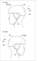
- FIG. 1 is a diagram showing a protective device 1 according to an embodiment.
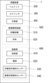
- FIG. 2 is a block diagram showing a schematic configuration of the protective device 1.
- the protective device 1 is a wearable type protective device that is worn by a person to be protected, and is a device for protecting the head and neck of the wearer (person to be protected).
- the protective device 1 includes a helmet 200, an airbag 300, a biasing unit 400, an inflation source supply unit 500, an activation unit 600, and the like, which are protective equipment worn on the head of the wearer (person to be protected) and for protecting the head.
- the protective device 1 is configured to protect the neck of the wearer (person to be protected) by activating when a predetermined activation condition is met.
- the wearer who wears the protective device 1 and the person to be protected are treated as synonymous.
- the "neck” refers to a narrow part that connects the human head and the torso.
- the part of the “neck” that is mainly located on the back side of the head is called the “back neck”.
- the “back neck” may also be called the “nape”.
- the part of the “neck” that is located on the front side opposite the "posterior neck” is called the “anterior neck.”
- the “anterior neck” is sometimes also called the "anterior throat.”
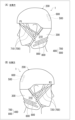
- FIG. 1 in the upper part is a perspective view of the helmet 200 viewed from the left side, and (B) is a perspective view of the helmet 200 viewed from the right side.
- Fig. 1 also shows the state in which the wearer is wearing (attaching) the helmet 200.
- Fig. 1 also shows the state before the protective device 1 is activated.
- the helmet 200 in this embodiment is a half-type (approximately hemispherical) helmet.
- the helmet 200 is equipped with a fixing strap 220 for fixing the helmet 200 to the wearer (person to be protected), etc.
- the helmet 200 itself can be a known one, and an inner cushion (not shown) for absorbing shock in the event of a fall, etc. may be provided on the inside.
- the inner cushion may be made of polystyrene foam, such as expanded polystyrene beads (EPS: Expanded Poly Styrene).
- the helmet 200 may be made of, for example, ABS (Acrylonitrile Butadiene Styrene) resin or PC (Poly Carbonate) resin.
- the fixing strap 220 is a so-called chin strap.
- the fixing strap 220 is a string-like body that is hung around the wearer's chin to fix the helmet 200 to the wearer's head.
- the form of the fixing strap 220 is not particularly limited, and any known fixing strap can be used.
- the airbag 300 is a bag configured to inflate and deploy when gas, an example of an inflation source, is supplied from the inflation source supply unit 500 when the protective device 1 is activated. Before the protective device 1 is activated, the airbag 300 is stored in a folded state (i.e., in a deflated state) inside the helmet 200.
- the inflation source supply unit 500 is activated by the activation unit 600.
- the activation unit 600 activates the inflation source supply unit 500
- the inflation source supply unit 500 starts to supply gas to the airbag 300, which in turn inflates and deploys the airbag 300.
- the inflation source supply unit 500 includes a storage container 510 that stores gas in a pressurized state to be supplied to the airbag 300, and a valve body 520 that closes a gas exhaust port formed in the storage container 510.
- the storage container 510 Before the protective device 1 is activated (before the inflation source supply unit 500 is activated), the storage container 510 is sealed by the valve body 520. The sealed state of the storage container 510 is released by the opening of the valve body 520 by the activation unit 600, and the pressurized gas stored in the storage container 510 is discharged from the gas exhaust port.
- the valve body 520 may be provided with an actuator (not shown), and may be configured so that the valve body 520 is opened by the activation of the actuator.
- the operating mechanism for opening the valve body 520 of the storage container 510 is not particularly limited.
- the valve body 520 may be formed of a thin metal plate member, and the valve body 520 may be opened by the activation unit 600 operating a splitting mechanism that splits the metal plate member that constitutes the valve body 520.
- the gas exhaust port of the storage container 510 and the gas inlet port of the airbag 300 are connected to each other, and gas is supplied to the airbag 300.
- the gas exhaust port of the storage container 510 and the gas inlet port of the airbag 300 are connected, for example, by a conduit (not shown), and the gas exhausted from the gas exhaust port of the storage container 510 may be supplied to the airbag 300 through this conduit.
- the activation unit 600 is not particularly limited as long as it is capable of activating the inflation source supply unit 500, and may, for example, include a control unit 610, a power source 620, an operating condition detection sensor 630, a wearing state detection sensor 640, and the like.
- the control unit 610 is, for example, a controller (control unit) that controls the actuator of the valve body 520.
- the power source 620 is a power supply source that supplies power to the control unit 610, the operating condition detection sensor 630, the wearing state detection sensor 640, and the like, and may be, for example, a lithium-ion battery or a dry cell.
- valve body 520 When the actuator of the valve body 520 is activated by an activation command signal output from the control unit 610, the valve body 520 is opened, and as a result, the inflation source supply unit 500 is activated, and gas is supplied from the inflation source supply unit 500 to the airbag 300.
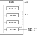
- FIG. 3 is a diagram showing the configuration of the control unit 610.
- the control unit 610 includes a processor 611, a memory unit 612, and an input/output unit 613.
- the processor 611 comprehensively executes various types of arithmetic processing in the control unit 610.
- the processor 611 may have arithmetic processing means such as a CPU (Central Processing Unit), a DSP (Digital Signal Processor), or an FPGA (Field-Programmable Gate Array).
- the memory unit 612 includes, for example, a main memory unit and an auxiliary memory unit.
- the main memory unit of the memory unit 612 includes, for example, a RAM (Random Access Memory) or a ROM (Read Only Memory), and caches information such as programs and data used in arithmetic processing by the processor 611.
- the main memory unit of the memory unit 612 may be formed integrally with the processor 611.
- the auxiliary memory unit of the memory unit 612 may be composed of, for example, a volatile memory such as a RAM, a non-volatile memory such as a ROM, or a storage medium such as an EPROM (Erasable Programmable ROM).
- the auxiliary memory unit of the memory unit 612 stores, for example, an operating system (OS), various programs, various tables, and the like for executing the operation of the protection device 1.
- the input/output unit 613 is an interface that inputs information (detection results, etc.) from various sensors such as the operating condition detection sensor 630 and the wearing state detection sensor 640, and outputs information (control signals, etc.) to various sensors and other devices.
- the protection device 1 also has a power switch (not shown), and the status signal of the power switch is also input to the input/output unit 613.
- the operating condition detection sensor 630 is a sensor for detecting that a predetermined operating condition has been met.
- the predetermined operating condition is a condition under which the protective device 1 should be activated (which can also be said to be a condition under which the inflation source supply unit 500 should be started), and examples include a fall of a bicycle ridden by a wearer wearing the helmet 200, and other conditions under which the wearer is exposed to danger.
- the operating condition detection sensor 630 may be, for example, an acceleration sensor, a gyro sensor (angular velocity sensor), etc.
- the operating condition detection sensor 630 may also be a vital sensor that detects the wearer's brain waves. The vital sensor may detect brain waves different from normal brain waves to detect a dangerous state of the wearer.
- the vital sensor may be a contact sensor that contacts the wearer's head, or a non-contact sensor.
- the operating condition detection sensor 630 may include, for example, at least one of the above-mentioned acceleration sensors, gyro sensors (angular velocity sensors), and vital sensors. Of course, the operating condition detection sensor 630 may be a combination of multiple types of sensors, including an acceleration sensor, a gyro sensor (angular velocity sensor), and a vital sensor.
- the operating condition detection sensor 630 is not particularly limited as long as it can detect the operating conditions, and can be replaced by a detection device other than the above-mentioned sensors (for example, a camera or a millimeter wave radar). Since the protection device 1 is equipped with the operating condition detection sensor 630, the activation unit 600 can activate the protection device 1 (activate the expansion source supply unit 500) at the appropriate timing.
- the wearing state detection sensor 640 is a sensor that detects the contact state between the wearer's head and the helmet 200.
- the wearing state detection sensor 640 may be, for example, a pressure sensor.
- the control unit 610 can determine whether the helmet 200 is being worn on the head based on the detection signal of the wearing state detection sensor 640.
- the wearing state detection sensor 640 may be, for example, multiple, arranged inside the helmet 200. In this case, the control unit 610 may determine that the helmet 200 is being worn when the detection signals from the multiple wearing state detection sensors 640 are signals indicating a contact state with the head.
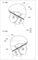
- FIG. 4 is a diagram showing the state in which the protective device 1 according to the first embodiment is activated.
- (A) in the upper part is a perspective view of the helmet 200 viewed from the left side
- (B) is a perspective view of the helmet 200 viewed from the right side.
- the airbag 300 to which gas is supplied from the inflation source supply unit 500 is pulled out from the inner space of the helmet 200 to the outside during the process of inflation and deployment, and is deployed to protect the back of the head and neck of the wearer as shown in FIG. 4.
- the airbag 300 In the deployed state, the airbag 300 has a generally U-shaped cross section and is configured to cover the wearer's back neck and both sides of the neck.
- the airbag 300 deployed by the activation of the protective device 1 covers the wearer's neck, thereby protecting the neck of the wearer.
- the airbag 300 is configured to protect the wearer's back head by covering it in the deployed state.
- the protective device 1 includes a biasing portion 400 formed integrally with the airbag 300, which inflates and deploys the inflation source supply portion 500 when activated.
- the biasing portion 400 is a member for biasing the airbag 300 against at least one of the side and rear of the neck of the wearer by utilizing the inflation pressure of the airbag 300.
- the biasing portion 400 is stored inside the helmet 200 before the protective device 1 is activated, and is drawn out together with the airbag 300 from the inside of the helmet 200 to the outside when the protective device 1 is activated.
- the biasing portion 400 has a biasing strap 700 and a shape retaining portion 800.
- the biasing strap 700 is a string-like member having one end connected to the front positions P1 and P2 of the helmet 200 and the other end connected to the airbag 300.
- the biasing strap 700 is arranged on both the left and right sides of the helmet 200 in response to the operation of the protection device 1.
- the one arranged on the left side of the helmet 200 is called the left biasing strap 710
- the one arranged on the right side of the helmet 200 is called the right biasing strap 720.
- the biasing strap 700 is composed of a left biasing strap 710 and a right biasing strap 720.
- two left biasing straps 710 and two right biasing straps 720 are arranged on the left and right sides of the helmet 200, but the number of these is not particularly limited.
- Reference numeral 330 in FIG. 4A indicates the left front edge of the airbag 300.
- Reference numeral 340 in FIG. 4B indicates the right front edge of the airbag 300.
- the left front and right front here refer to the directions of the airbag 300 after deployment based on the front-rear and left-right directions of the helmet 200.
- one end of the left biasing strap 710 is connected to the front position P1 of the helmet 200, and the other end is connected to the left front edge 330 of the airbag 300.
- the left biasing strap 710 is configured to fit, for example, the left side of the wearer's face when the protective device 1 is activated. In the example shown in FIG.
- one end of the right biasing strap 720 is connected to the front position P2 of the helmet 200, and the other end is connected to the right front edge 340 of the airbag 300.
- the right-side biasing strap 720 is configured to fit, for example, to the right side of the wearer's face when the protection device 1 is activated.
- the material forming the biasing straps 700 is not particularly limited, but for example, cloth, rubber, wire, etc. can be used.
- the biasing straps 700 are configured to bias the airbag 300 from the rear of the wearer's neck toward the front of the neck as the protective device 1 is activated.
- the biasing straps 700 may be stored inside the helmet 200 so as to be positioned along the inside of the side opening edge of the helmet 200, and are pulled out of the helmet 200 together with the airbag 300 as the protective device 1 is activated.
- the shape retention portion 800 is configured, for example, as a frame member fixed integrally with the airbag 300, and retains the shape of the airbag 300 deployed when the protective device 1 is activated, while suppressing deformation of the airbag 300 in a direction away from the wearer's neck.
- the shape retention portion 800 is configured, for example, including an elastic metal or resin.
- two shape retention portions 800 molded into a roughly U-shape in cross section are fixed along the lateral direction of the airbag 300.
- the number, position, shape, etc. of the shape retention portions 800 provided on the airbag 300 are not particularly limited.
- the shape retention portion 800 fixed integrally with the airbag 300 is stored in the interior of the helmet 200 along the opening edge portion (for example, the rear opening edge portion) of the helmet 200 before the protective device 1 is activated. Then, it is pulled out of the helmet 200 together with the airbag 300 as the protective device 1 is activated.
- the shape retaining part 800 may form part of the outer shell of the helmet 200.
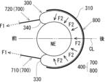
- Figure 5 is a diagram explaining the function of the biasing straps 700 (left biasing strap 710, right biasing strap 720) and shape-retaining part 800 as the biasing part 400.
- Figure 5 shows a schematic diagram of the biasing straps 700 (left biasing strap 710, right biasing strap 720) and shape-retaining part 800 biasing the airbag 300, which has been deployed when the protection device 1 is activated, toward the wearer's neck. More specifically, the cross section of the airbag 300 and biasing part 400 after deployment at the wearer's neck position is shown in schematic form. In Figure 5, the wearer's neck is indicated by the symbol NE.
- the left biasing strap 710 and the right biasing strap 720 have one end connected to the front positions P1 and P2 of the helmet 200, respectively, and the other end connected to the left front edge 330 and the right front edge 340 of the airbag 300, respectively.
- the length dimensions of the left biasing strap 710 and the right biasing strap 720 and the positions at which their one ends are attached to the helmet 200 are adjusted so that the inflation pressure of the airbag 300 acts on the left biasing strap 710 and the right biasing strap 720 during the inflation process (deployment process) of the airbag 300.
- the left side biasing strap 710 and the right side biasing strap 720 can bias the airbag 300 from the rear neck side of the wearer toward the front of the neck.
- the biasing straps 700 (left biasing strap 710, right biasing strap 720) have elasticity.
- the airbag 300 can be biased with a greater biasing force from the rear of the wearer's neck toward the front of the neck.
- the protection device 1 when activated, the restraining effect of restraining the wearer's neck can be further improved.
- FIG. 5 shows an example of the direction of the biasing force of the left biasing strap 710 and the right biasing strap 720 biasing the airbag 300 when the protection device 1 is activated.
- the symbol CL in FIG. 5 is a front-to-rear central axis that passes through the center of the helmet 200 in the left-to-right direction and extends in the front-to-rear direction.
- the front positions P1 and P2 at which one end of the left biasing strap 710 and the right biasing strap 720 are fixed to the helmet 200 may be set to a position closer to the front-to-rear central axis CL of the helmet 200 than the left front edge 330 and the right front edge 340 at which the other end of the left biasing strap 710 and the right biasing strap 720 are fixed to the airbag 300.
- the direction of the biasing force shown by the symbol F1 in FIG. 5 can be directed toward the front inside of the helmet 200.
- the "inside” refers to the inside in the left-right direction of the helmet 200, and can also be said to be the side of the front-to-rear central axis CL.
- the airbag 300 can be made to fit in a U-shape from the back of the wearer's neck to the left and right sides of the neck, further enhancing the restraining effect of restraining the wearer's neck.
- the shape-retaining part 800 is formed as a frame body having a U-shape.
- the shape-retaining part 800 is fixed integrally along the outer periphery 310 of the airbag 300.
- the outer periphery 310 of the airbag 300 refers to the part facing the opposite side to the side facing and contacting the neck of the wearer after the airbag 300 is deployed into a roughly U-shape.
- the part of the airbag 300 that faces the neck of the wearer and covers the neck after the airbag 300 is deployed into a roughly U-shape is also called the "inner periphery".
- the shape-retaining part 800 When fixing the shape-retaining part 800 to the outer periphery 310 of the airbag 300, the shape-retaining part 800 may be disposed on the outer surface (surface exposed to the outside) of the airbag 300 or on the inner surface (surface into which gas is introduced) of the airbag 300. However, the shape-retaining part 800 may be fixed along the inner periphery of the airbag 300.
- the shape-retaining portion 800 which is disposed integrally with the airbag 300, is subjected to the inflation pressure of the airbag 300 when it is inflated (deployed).
- the shape-retaining portion 800 is formed as a frame body having a U-shape, so that the shape-retaining portion 800 resists the inflation pressure of the airbag 300, retains the shape of the deployed airbag 300, and functions to suppress deformation of the airbag 300 in a direction away from the wearer's neck.
- the shape-retaining portion 800 resists the inflation pressure by its rigidity, and urges the airbag 300 toward the neck (rear neck, side neck) as a reaction force against the inflation pressure.
- the solid arrow indicated by the symbol F2 in FIG. 5 illustrates the direction of the urging force of the shape-retaining portion 800 urging the airbag 300 when the protection device 1 is activated.
- the above-mentioned shape-retaining portion 800 can maintain the airbag 300 in a state of close contact with the wearer's neck (rear neck, side neck) after inflation. As a result, the effect of restraining the wearer's neck is enhanced, and bending of the neck can be effectively suppressed.
- the shape-retaining portion 800 is fixed integrally along the outer periphery 310 of the airbag 300, so that when the protection device 1 is activated, the airbag 300 can be biased toward the wearer's neck with a larger biasing force, and the neck restraining effect of the airbag 300 can be further enhanced. In other words, excessive bending of the wearer's neck can be suitably suppressed.
- the shape-retaining portion 800 may be composed of an elastic metal or resin. In this way, when the shape-retaining portion 800 receives the inflation pressure of the airbag 300, a larger repulsive force is generated, and the airbag 300 can be biased toward the wearer's neck with a larger biasing force.
- the protective device 1 includes the airbag 300 that protects the neck of the wearer, as well as the biasing portion 400 (biasing strap 700, shape-retaining portion 800) that biases the airbag 300 toward the neck, so that a gap is unlikely to form between the airbag 300 and the neck after inflation, and the neck can be appropriately restrained.
- the protective device 1 does not need to completely restrain the movement of the wearer's head and neck when activated, and may restrain the neck with some movement.
- the protective device 1 may allow the movement of the neck so that the wearer's neck is within a range that does not receive damage when falling, etc.
- the deployed airbag 300 does not cover the entire circumference of the wearer's neck, but protects the back of the neck and both sides of the neck in a U-shape, so the wearer's throat is not excessively constricted when the protective device 1 is activated.
- one end of the biasing strap 700 that biases the airbag 300 forward is fixed to the helmet 200, and the fixing strap 220 and the airbag 300 are not particularly connected, so the wearer's throat is not excessively constricted when the protective device 1 is activated.
- the above-mentioned protective device 1 can be modified in various ways. Modified examples of the protective device 1 are described below.
- FIG. 6 is a diagram for explaining a first modification of the protective device 1.
- the helmet 200 according to the first modification is configured to cover at least the upper part of the wearer's ears when worn on the head of the wearer. That is, the helmet 200 according to the first modification has an ear cover part 210, and the ear cover part 210 covers at least the upper part of the wearer's ears when worn on the head.
- the other structures are the same as those of the protective device 1 described above.
- the biasing straps 700 left biasing strap 710, right biasing strap 720
- the helmet 200 are stored inside the helmet 200 along the side opening edge indicated by the reference numeral 230 before the protective device 1 is activated.
- the biasing straps 700 when the biasing straps 700 (left biasing strap 710, right biasing strap 720) are pulled out to the outside of the helmet 200 along with the airbag 300 that inflates and deploys when the protective device 1 is activated, the biasing straps 700 can be made less likely to get caught on the wearer's ears.
- ⁇ Second Modification> 7 is a perspective view showing a state in which the protection device 1 according to the second modification is activated.
- (A) in the upper part is a perspective view of the helmet 200 viewed from the left side
- (B) is a perspective view of the helmet 200 viewed from the right side.
- the biasing strap 700 is fixed (connected) to the outer periphery 310 of the airbag 300. That is, one end side of the biasing strap 700 is connected to the front positions P1 and P2 of the helmet 200, and the other end side of the biasing strap 700 (left side biasing strap 710, right side biasing strap 720) is connected to the outer periphery 310 of the airbag 300.
- the biasing force F1 described in FIG. 5 can be directed further inward of the helmet 200 (toward the front-rear central axis CL).
- the inflated airbag 300 can be more easily fitted to the left and right sides of the neck of the wearer.
- the airbag 300 can be more appropriately fitted in a U-shape from the back of the neck to the left and right sides of the neck of the wearer, and the restraining effect of restraining the neck of the wearer can be further improved.
- FIG. 1 In the modified example shown in FIG.
- the ends of the left biasing strap 710 and the right biasing strap 720 on the airbag 300 side may be connected to surround the entire circumferential direction of the outer periphery 310 of the airbag 300 with the biasing strap 700.
- the shape-retaining portion 800 can be used in combination with the biasing strap 700.
- FIG. 8 is a perspective view showing a state in which the protection device 1 according to the third modified example is activated.
- (A) in the upper part is a perspective view of the helmet 200 viewed from the left side
- (B) is a perspective view of the helmet 200 viewed from the right side.
- the other end side of the biasing strap 700 (left side biasing strap 710, right side biasing strap 720) is connected to the shape retaining part 800.
- one end side of the biasing strap 700 is connected to the front positions P1 and P2 of the helmet 200.
- the end of the biasing strap 700 is connected to the end 810 of the shape retaining part 800 formed into a roughly U-shape.
- an end of the biasing strap 700 is connected to an end 810 of a shape-retaining portion 800 that is integral with the airbag 300, and these are connected together.
- the shape-retaining portion 800 that is integral with the airbag 300 can be pulled directly forward by the biasing strap 700.
- the tension acting on the biasing strap 700 can be directly transmitted to the shape-retaining portion 800, so that the airbag 300 can be biased more efficiently against the wearer's back neck and neck. This further enhances the restraining effect that restrains the wearer's neck, and further improves the effect of neck protection.
- the biasing portion 400 has been described as including both the biasing straps 700 (left side biasing strap 710, right side biasing strap 720) and the shape-retaining portion 800, but this is not limited thereto, and the biasing straps 700 and the shape-retaining portion 800 can each be used alone.
- the biasing portion 400 of the protective device 1 may have only one of the biasing straps 700 and the shape-retaining portion 800.
- the inflation pressure of the airbag 300 is used to bias the airbag 300 against the wearer's neck when the protective device 1 is activated, thereby achieving a neck restraint effect.
- the directions in which the biasing straps 700 extend (the directions in which the biasing straps 700 extend and the directions in which the shape-retaining parts 800 extend, as well as their relative directions, are not particularly limited, and the embodiment shown in FIG. 8 is merely one example.
- ⁇ Fourth Modification> 9 is a perspective view showing a state in which the protection device 1 according to the fourth modification is activated.
- (A) is illustrated as a perspective view of the helmet 200 viewed from the left side
- (B) is illustrated as a perspective view of the helmet 200 viewed from the right side.
- the protection device 1 according to the fourth modification is provided with only the biasing straps 700 (left side biasing strap 710, right side biasing strap 720) as the biasing portion 400, and the shape retaining portion 800 is not provided on the airbag 300.
- an auxiliary strap 730 is integrally attached to the outer surface of the outer periphery portion 310 of the airbag 300, and the auxiliary strap 730 goes around along the outer periphery portion 310.
- Each end of the auxiliary strap 730 is continuously connected to the left side biasing strap 710 and the right side biasing strap 720. That is, the biasing strap 700 can be regarded as a single strap in which the left-side biasing strap 710, the auxiliary strap 730, and the right-side biasing strap 720 are continuous. Note that, in the example shown in Fig.
- the protection device 1 is provided with one biasing strap 700 in which the left-side biasing strap 710, the auxiliary strap 730, and the right-side biasing strap 720 are continuous, but the number of biasing straps 700 is not particularly limited, and may be two, or of course, the protection device 1 may be provided with three or more biasing straps 700.
- the biasing strap 700 configured in this manner has each end connected to the front positions P1, P2 of the helmet 200, and the auxiliary strap 730 located in the middle is joined to the outer periphery 310 of the airbag 300 and is configured to go around the outer periphery 310.
- the airbag 300 can be biased with a greater biasing force from the rear of the wearer's neck toward the front of the neck, further enhancing the restraining effect of restraining the wearer's neck when the protective device 1 is activated.
- the protective device 1 may adopt a configuration different from the above-described embodiments and each modified example.
- the activation unit 600 (control unit 610) activates the inflation source supply unit 500 based on the detection signal of the activation condition detection sensor 630.
- the helmet 200 may be provided with a manual operation unit (not shown) that is manually operated by the wearer, and the protective device 1 may be configured to operate when the wearer operates the manual operation unit.
- an appropriate mechanical mechanism for example, a combination of mechanical elements such as a spring or wire
- the protective device 1 may be operated by the wearer operating the manual operation unit.
- the specific structure of the manual operation unit is not particularly limited, and for example, a manual switch or a lock pin that can be operated by the wearer may be provided on the helmet 200, and a structure in which the gas outlet of the storage container 510 is opened by operating such a manual operation unit may be adopted.
- the inflation source supply unit 500 may be a pyrotechnic gas generator used to inflate the airbag 300.
- This type of gas generator is well known, and detailed description will be omitted.
- the gas generator may include a housing that contains a gas generating agent inside, and a pyrotechnic igniter that is activated by the supply of an operating current and ignites the gas generating agent in the housing, and may supply inflation gas generated by combustion of the gas generating agent to the airbag 300 through an appropriate conduit.
- the protective device 1 described above has been described using an example in which the airbag 300 is stored in a folded state inside the helmet 200 before activation, but the airbag 300 may be stored in a place other than the inside of the helmet 200.
- the airbag 300 may be attached to the outer shell of the helmet 200 in a state where it is covered with a cover.
- Protective device 200 Helmet 220: Fixing strap 300: Airbag 400: Pressing section 500: Inflation source supply section 700: Pressing strap 800: Shape retention section
Landscapes
- Engineering & Computer Science (AREA)
- Mechanical Engineering (AREA)
- Health & Medical Sciences (AREA)
- General Health & Medical Sciences (AREA)
- Physical Education & Sports Medicine (AREA)
- Textile Engineering (AREA)
- Business, Economics & Management (AREA)
- Emergency Management (AREA)
- Helmets And Other Head Coverings (AREA)
Abstract
保護装置は、着用者の頭部に装着可能なヘルメットと、ヘルメットを頭部に固定するための固定用ストラップと、保護装置の作動前においてヘルメットに畳まれた状態で収容されたエアバッグと、保護装置の作動時にエアバッグに膨張源を供給する膨張源供給部を備え、エアバッグは、膨張源供給部から供給される膨張源によって膨張および展開することによって着用者の後頸部から双方の側頸部に渡りこれらを覆うように構成されており、エアバッグと一体に形成されており、エアバッグの膨張圧を利用して当該エアバッグを着用者の側頸部および後頸部の少なくとも一方に付勢する付勢部を、更に備える。
Description
本発明は、頭部および頸部を保護する保護装置に関する。
従来から、自転車等の乗員の頭部を保護する保護装置としてヘルメットが広く知られているが、通常のヘルメットは頸椎を保護する機能は有していない。
これに関連して、保護対象者の頸部を保護可能なエアバッグ装置も提案されている(例えば、特許文献1等を参照)。
特許文献1には、ヘルメットの背部内側に膨張可能なエアバッグを収容しておき、作動時に、貯蔵チャンバに貯蔵された加圧ガスをエアバッグに供給することによって当該エアバッグを膨張させ、ヘルメットの着用者における頸部をエアバッグによって保護する技術が開示されている。
ところで、自転車の転倒時においては、その衝撃によって頸部と頭部との境界付近を中心に頭部あるいは頸部が急角度で折れ曲がり、これによって頸部がダメージを受けるケースが少なくない。しかしながら、従来における保護装置においては、着用者の頸部を膨張後のエアバッグによって覆うことはできたとしても、頸部の屈曲を拘束するという観点からは十分とは言えず、過度な屈曲に起因する頸部へのダメージの予防効果が高いとは言えなかった。
本開示の技術は、上記した実情に鑑みてなされたものであり、保護対象者の頸部における過度な屈曲を抑制可能な技術を提供することを目的とする。
本開示は、以下の態様により上記課題を解決する。すなわち、本開示に係る技術の要旨は以下の通りである。
(態様1)
上記課題を解決するための本開示に係る技術は、
着用者の頭部および頸部を保護する保護装置であって、
着用者の頭部に装着可能なヘルメットと、
前記ヘルメットを頭部に固定するための固定用ストラップと、
前記保護装置の作動前において、前記ヘルメットに畳まれた状態で収容されたエアバッグと、
前記保護装置の作動時に、前記エアバッグに膨張源を供給する膨張源供給部と、
を備え、
前記エアバッグは、前記膨張源供給部から供給される膨張源によって膨張および展開することによって着用者の後頸部から双方の側頸部に渡りこれらを覆うように構成されており、
前記エアバッグと一体に形成されており、前記エアバッグの膨張圧を利用して当該エアバッグを着用者の側頸部および後頸部の少なくとも一方に付勢する付勢部を、更に備える。
(態様1)
上記課題を解決するための本開示に係る技術は、
着用者の頭部および頸部を保護する保護装置であって、
着用者の頭部に装着可能なヘルメットと、
前記ヘルメットを頭部に固定するための固定用ストラップと、
前記保護装置の作動前において、前記ヘルメットに畳まれた状態で収容されたエアバッグと、
前記保護装置の作動時に、前記エアバッグに膨張源を供給する膨張源供給部と、
を備え、
前記エアバッグは、前記膨張源供給部から供給される膨張源によって膨張および展開することによって着用者の後頸部から双方の側頸部に渡りこれらを覆うように構成されており、
前記エアバッグと一体に形成されており、前記エアバッグの膨張圧を利用して当該エアバッグを着用者の側頸部および後頸部の少なくとも一方に付勢する付勢部を、更に備える。
(態様2)
態様1において、前記付勢部は、前記保護装置の作動前において前記ヘルメットの内空側に格納されており、前記保護装置の作動に伴って前記エアバッグと共に前記ヘルメットの内空側から外部に引き出されてもよい。
態様1において、前記付勢部は、前記保護装置の作動前において前記ヘルメットの内空側に格納されており、前記保護装置の作動に伴って前記エアバッグと共に前記ヘルメットの内空側から外部に引き出されてもよい。
(態様3)
態様1又は2において、前記付勢部は、一端側が前記ヘルメットにおける前部位置に接続され、前記保護装置の作動時に着用者の後頸部側から頸部前方に向けて前記エアバッグを付勢するように構成された付勢用ストラップを含んでいてもよい。
態様1又は2において、前記付勢部は、一端側が前記ヘルメットにおける前部位置に接続され、前記保護装置の作動時に着用者の後頸部側から頸部前方に向けて前記エアバッグを付勢するように構成された付勢用ストラップを含んでいてもよい。
(態様4)
態様3において、前記付勢用ストラップは弾性を有していてもよい。
態様3において、前記付勢用ストラップは弾性を有していてもよい。
(態様5)
態様3において、前記付勢用ストラップは、前記エアバッグの外周部に固定されていてもよい。
態様3において、前記付勢用ストラップは、前記エアバッグの外周部に固定されていてもよい。
(態様6)
態様3において、前記ヘルメットは、着用者の頭部に装着された状態において、当該着用者における少なくとも耳の上部を覆うように構成されていてもよい。
態様3において、前記ヘルメットは、着用者の頭部に装着された状態において、当該着用者における少なくとも耳の上部を覆うように構成されていてもよい。
(態様7)
態様1又は2において、前記付勢部は、前記保護装置の作動時に展開した前記エアバッグの形状を保持すると共に着用者の頸部から離間する方向への当該エアバッグの変形を抑制する形状保持用部を含んでいてもよい。
態様1又は2において、前記付勢部は、前記保護装置の作動時に展開した前記エアバッグの形状を保持すると共に着用者の頸部から離間する方向への当該エアバッグの変形を抑制する形状保持用部を含んでいてもよい。
(態様8)
態様7において、前記形状保持部は、前記エアバッグにおける外周部に固定されていてもよい。
態様7において、前記形状保持部は、前記エアバッグにおける外周部に固定されていてもよい。
(態様9)
態様7において、前記形状保持部は、弾性を有する金属または樹脂を含んでいてもよい。
態様7において、前記形状保持部は、弾性を有する金属または樹脂を含んでいてもよい。
(態様10)
態様7において、前記形状保持部は、前記保護装置の作動前において前記ヘルメットの開口縁部に沿って前記ヘルメットの内空側に格納されており、前記保護装置の作動に伴って前記エアバッグと共に前記ヘルメットの内空側から外部に引き出されてもよい。
態様7において、前記形状保持部は、前記保護装置の作動前において前記ヘルメットの開口縁部に沿って前記ヘルメットの内空側に格納されており、前記保護装置の作動に伴って前記エアバッグと共に前記ヘルメットの内空側から外部に引き出されてもよい。
(態様11)
態様7において、前記付勢部は、一端側が前記ヘルメットにおける前部位置に接続され、前記保護装置の作動時に前記エアバッグを着用者の後頸部側から頸部前方に向けて付勢するように構成された付勢用ストラップを更に含み、
前記付勢用ストラップの他端側が前記形状保持部に接続されていてもよい。
態様7において、前記付勢部は、一端側が前記ヘルメットにおける前部位置に接続され、前記保護装置の作動時に前記エアバッグを着用者の後頸部側から頸部前方に向けて付勢するように構成された付勢用ストラップを更に含み、
前記付勢用ストラップの他端側が前記形状保持部に接続されていてもよい。
(態様12)
態様1又は2において、前記ヘルメットに装着され、前記膨張源供給部を起動させる起動部を更に備え、
前記起動部は、所定の作動条件が成立したことを検知するための作動条件検知センサーを有していてもよい。
態様1又は2において、前記ヘルメットに装着され、前記膨張源供給部を起動させる起動部を更に備え、
前記起動部は、所定の作動条件が成立したことを検知するための作動条件検知センサーを有していてもよい。
本開示によれば、保護対象者の頸部における過度な屈曲を抑制可能な技術を提供できる。
以下に、図面を参照して本開示の実施形態に係る保護装置を説明する。なお、実施形態における各構成及びそれらの組み合わせ等は、一例であって、本開示の主旨から逸脱しない範囲内で、適宜、構成の付加、省略、置換、及びその他の変更が可能である。本開示は、実施形態によって限定されることはなく、請求の範囲によってのみ限定される。
本実施形態に係る着用者の頭部および頸部を保護する保護装置は、
着用者の頭部に装着可能なヘルメットと、
ヘルメットを頭部に固定するための固定用ストラップと、
保護装置の作動前において、ヘルメットに畳まれた状態で収容されたエアバッグと、
保護装置の作動時に、エアバッグに膨張源を供給する膨張源供給部と、
を備え、
エアバッグは、膨張源供給部から供給される膨張源によって膨張および展開することによって着用者の後頸部から双方の側頸部に渡りこれらを覆うように構成されており、
エアバッグと一体に形成されており、エアバッグの膨張圧を利用して当該エアバッグを着用者の側頸部および後頸部の少なくとも一方に付勢する付勢部を、更に備える。
着用者の頭部に装着可能なヘルメットと、
ヘルメットを頭部に固定するための固定用ストラップと、
保護装置の作動前において、ヘルメットに畳まれた状態で収容されたエアバッグと、
保護装置の作動時に、エアバッグに膨張源を供給する膨張源供給部と、
を備え、
エアバッグは、膨張源供給部から供給される膨張源によって膨張および展開することによって着用者の後頸部から双方の側頸部に渡りこれらを覆うように構成されており、
エアバッグと一体に形成されており、エアバッグの膨張圧を利用して当該エアバッグを着用者の側頸部および後頸部の少なくとも一方に付勢する付勢部を、更に備える。
<実施形態>
図1は、実施形態に係る保護装置1を示す図である。図2は、保護装置1の概略構成を示すブロック図である。保護装置1は、保護対象者に装着されるウェアラブルタイプの保護装置であり、着用者(保護対象者)の頭部および頸部を保護するための装置である。保護装置1は、着用者(保護対象者)の頭部に装着されると共に頭部を保護するための保護具であるヘルメット200、エアバッグ300、付勢部400、膨張源供給部500、起動部600等を備えている。保護装置1は、所定の作動条件が成立すると作動することによって着用者(保護対象者)の頸部を保護するように構成されている。本明細書において、保護装置1を着用する着用者と保護対象者は同義として取り扱う。また、本明細書において、「頸部」とは、ヒトの頭部と胴体を繋ぐ細くなっている部分を指す。また、「頸部」のうち、主として後頭部側に位置する部位を「後頸部」と呼ぶ。「後頸部」は「うなじ部」とも呼ばれる場合がある。また、「頸部」のうち、「後頸部」とは反対側の前側に位置する部位を「前頸部」と呼ぶ。「前頸部」は、「前喉部」とも呼ばれる場合がある。
図1は、実施形態に係る保護装置1を示す図である。図2は、保護装置1の概略構成を示すブロック図である。保護装置1は、保護対象者に装着されるウェアラブルタイプの保護装置であり、着用者(保護対象者)の頭部および頸部を保護するための装置である。保護装置1は、着用者(保護対象者)の頭部に装着されると共に頭部を保護するための保護具であるヘルメット200、エアバッグ300、付勢部400、膨張源供給部500、起動部600等を備えている。保護装置1は、所定の作動条件が成立すると作動することによって着用者(保護対象者)の頸部を保護するように構成されている。本明細書において、保護装置1を着用する着用者と保護対象者は同義として取り扱う。また、本明細書において、「頸部」とは、ヒトの頭部と胴体を繋ぐ細くなっている部分を指す。また、「頸部」のうち、主として後頭部側に位置する部位を「後頸部」と呼ぶ。「後頸部」は「うなじ部」とも呼ばれる場合がある。また、「頸部」のうち、「後頸部」とは反対側の前側に位置する部位を「前頸部」と呼ぶ。「前頸部」は、「前喉部」とも呼ばれる場合がある。
図1において、上段の(A)は、ヘルメット200を左側方から眺めた斜視図として図示され、(B)は、ヘルメット200を右側方から眺めた斜視図として図示されている。また、図1は、着用者がヘルメット200を着用(装着)した状態を示している。また、図1は、保護装置1が作動する前の状態を示している。
本実施形態におけるヘルメット200は、ハーフ型(略半球状)のヘルメットである。ヘルメット200は、当該ヘルメット200を着用者(保護対象者)に固定するための固定用ストラップ220等を備えている。ヘルメット200自体は公知のものを使用することができ、その内側には、転倒時などにおける衝撃を吸収するためのインナークッション(図示せず)が設けられていてもよい。インナークッションは、例えば発泡性ポリスチレンビーズ(EPS:Expanded Poly Styrene)などの発泡スチロールから構成されていてもよい。ヘルメット200は、例えばABS(Acrylonitrile Butadiene Styrene)樹脂やPC(Poly Carbonate)樹脂から形成されていてもよい。
固定用ストラップ220は、いわゆる顎紐である。固定用ストラップ220は、着用者の顎に掛けることによりヘルメット200を着用者の頭部に固定するための紐状体である。本実施形態において、固定用ストラップ220の態様は特に限定されず、公知の固定用ストラップを用いることができる。
エアバッグ300は、保護装置1の作動時に膨張源供給部500から膨張源の一例としてのガスが供給されることによって膨張および展開するように構成された袋体である。エアバッグ300は、保護装置1の作動前において、ヘルメット200の内空側に畳まれた状態(すなわち、収縮した状態)で収容されている。
膨張源供給部500は、起動部600によって起動する。起動部600が膨張源供給部500を起動させると、当該膨張源供給部500からエアバッグ300へのガスの供給が開始され、それに伴ってエアバッグ300が膨張し、展開する。例えば、膨張源供給部500は、エアバッグ300に供給するためのガスを加圧した状態で貯蔵する貯蔵容器510と、当該貯蔵容器510に形成されたガス排出口を閉鎖する弁体520を備えている。
保護装置1の作動前(膨張源供給部500の起動前)においては、弁体520によって貯蔵容器510が密封されている。そして、起動部600によって弁体520が開放されることによって貯蔵容器510の密封状態が解除され、貯蔵容器510内に貯蔵されていた加圧状態のガスがガス排出口から排出される。弁体520には図示しないアクチュエータが設けられていてもよく、当該アクチュエータが作動することによって弁体520が開放されるように構成されていてもよい。勿論、貯蔵容器510の弁体520を開放する作動機構は特に限定されない。例えば、弁体520を薄肉の金属板部材で構成し、起動部600が弁体520を構成する金属板部材を開裂する開裂機構を作動させることによって弁体520を開放してもよい。貯蔵容器510の弁体520が開放されると、貯蔵容器510のガス排出口とエアバッグ300のガス導入口が導通されることによって、エアバッグ300にガスが供給される。貯蔵容器510のガス排出口とエアバッグ300のガス導入口は、例えば図示しない導管によって接続されており、この導管を通じて貯蔵容器510のガス排出口から排出されるガスがエアバッグ300に供給されてもよい。
起動部600は、膨張源供給部500を起動させることの可能な構成であれば特に限定されないが、例えば、制御部610、電源620、作動条件検知センサー630、装着状態検知センサー640等を含んで構成されている。制御部610は、例えば、弁体520のアクチュエータを制御するコントローラー(コントロールユニット)である。電源620は、制御部610、作動条件検知センサー630、装着状態検知センサー640等に電力を供給する電力供給源であり、例えば、リチウムイオンバッテリーや乾電池であってもよい。制御部610から出力される作動指令信号によって弁体520のアクチュエータが作動すると、弁体520が開放される結果、膨張源供給部500が起動し、膨張源供給部500からエアバッグ300にガスが供給される。
図3は、制御部610の構成を示す図である。制御部610は、プロセッサ611、記憶部612、及び入出力部613等を備える。プロセッサ611は、制御部610における各種の演算処理を統括的に実行する。プロセッサ611は、例えば、CPU(Central Processing Unit)、DSP(Digital Signal Processor)、又はFPGA(Field-Programmable Gate Array)などの演算処理手段を有していてもよい。
記憶部612は、例えば、主記憶部と、補助記憶部を備える。記憶部612の主記憶部は、例えば、RAM(Random Access Memory)又はROM(Read Only Memory)などを備え、プロセッサ611で演算処理に用いられるプログラムやデータ等の情報をキャッシュする。記憶部612の主記憶部は、プロセッサ611と一体に形成されてもよい。記憶部612の補助記憶部は、例えば、RAM等の揮発性メモリ、ROM等の不揮発性メモリ、EPROM(Erasable Programmable ROM)などの記憶媒体から構成されていてもよい。記憶部612の補助記憶部には、例えば、保護装置1の動作を実行するための、オペレーティングシステム(Operating System:OS)、各種プログラム、各種テーブルなどが記憶されている。入出力部613は、例えば、作動条件検知センサー630、装着状態検知センサー640等の各種センサーからの情報(検出結果等)の入力、及び各種センサーや他の装置への情報(制御信号等)の出力を行うインターフェイスである。また、保護装置1は、図示しない電源スイッチを有しており、電源スイッチの状態信号も入出力部613に入力される。
作動条件検知センサー630は、所定の作動条件が成立したことを検知するためのセンサーである。所定の作動条件とは、保護装置1を作動させるべき条件(膨張源供給部500を起動させるべき条件とも言える)であり、例えば、ヘルメット200を着用する着用者が乗る自転車の転倒時や、その他、着用者が危険に晒されている条件等の例が挙げられる。作動条件検知センサー630は、例えば、加速度センサー、ジャイロセンサー(角速度センサー)等であってもよい。また、作動条件検知センサー630は、着用者の脳波を検知するバイタルセンサーであってもよい。バイタルセンサーによって、平生時の脳波と異なる脳波を検出して、着用者の危険状態を検知してもよい。バイタルセンサーは、着用者の頭部に接触する接触式センサーであってもよいし、非接触式センサーであってもよい。作動条件検知センサー630は、例えば、上述した加速度センサー、ジャイロセンサー(角速度センサー)、バイタルセンサーのうち、少なくとも1種類を含んでいてもよい。勿論、作動条件検知センサー630として、加速度センサー、ジャイロセンサー(角速度センサー)、バイタルセンサーのうち、複数種類のセンサーを併用してもよい。また、作動条件検知センサー630は、作動条件を検知できれば特に限定されず、上記例示したセンサー以外の検知機器(例えば、カメラやミリ波レーダーなど)によって代替することができる。保護装置1は、作動条件検知センサー630を備えているため、起動部600が適切なタイミングで保護装置1を作動させる(膨張源供給部500を起動させる)ことができる。
装着状態検知センサー640は、着用者の頭部とヘルメット200との接触状態を検知するセンサーである。装着状態検知センサー640は、例えば感圧センサーであってもよい。制御部610は、装着状態検知センサー640の検知信号に基づいて、ヘルメット200が頭部に装着されている状態かどうかを判断することができる。装着状態検知センサー640は、例えばヘルメット200の内側に複数配置されていてもよい。この場合、制御部610は、複数の装着状態検知センサー640からの検知信号が頭部との接触状態を示す信号であるときにヘルメット200が着用されていると判断してもよい。
図4は、実施形態1に係る保護装置1が作動した状態を示す図である。上段の(A)は、ヘルメット200を左側方から眺めた斜視図として図示され、(B)は、ヘルメット200を右側方から眺めた斜視図として図示されている。保護装置1の作動時において、膨張源供給部500からガスが供給されるエアバッグ300は、膨張および展開する過程でヘルメット200の内空側から外部に引き出され、図4に示すように着用者の後頭部および頸部を保護するように展開状態となる。エアバッグ300は、展開した状態において、その横断面が概略U字形状を有しており、着用者の後頸部から双方の側頸部に渡りこれらを覆うように構成されている。保護装置1の作動によって展開したエアバッグ300が着用者の頸部を覆うことで、着用者における頸部を保護する。また、図4に示すように、エアバッグ300は、展開状態において着用者における後頭部も覆うことで保護するように構成されている。
本実施形態に係る保護装置1は、膨張源供給部500を起動時に膨張および展開するエアバッグ300と一体に形成された付勢部400を備えている。付勢部400は、エアバッグ300の膨張圧を利用して当該エアバッグ300を着用者の側頸部および後頸部の少なくとも一方に付勢するための部材である。本実施形態においては、付勢部400は、保護装置1の作動前においてヘルメット200の内空側に格納されており、保護装置1の作動に伴ってエアバッグ300と共にヘルメット200の内空側から外部に引き出されるようになっている。
本実施形態において、付勢部400は、付勢用ストラップ700および形状保持部800を有している。付勢用ストラップ700は、図4に示すように、一端側がヘルメット200における前部位置P1,P2に接続され、他端側がエアバッグ300に接続された紐状部材である。図4の(A)、(B)に示すように、付勢用ストラップ700は、保護装置1の作動に伴って、ヘルメット200の左右双方に配置されるようになっている。ヘルメット200の左側に配置される方を左側付勢用ストラップ710と呼び、ヘルメット200の右側に配置される方を右側付勢用ストラップ720と呼ぶ。付勢用ストラップ700は、左側付勢用ストラップ710および右側付勢用ストラップ720を含んで構成されている。図4に示す例では、ヘルメット200の左右に左側付勢用ストラップ710および右側付勢用ストラップ720が2本ずつ配置されているが、これらの数は特に限定されない。
図4の(A)に示す符号330は、エアバッグ300における左側前方縁部である。図4の(B)に示す符号340は、エアバッグ300における右側前方縁部である。ここでいう左側前方、右側前方とは、展開後のエアバッグ300において、ヘルメット200の前後左右方向を基準とした場合の方向を意味している。図4の(A)に示す例では、左側付勢用ストラップ710の一端がヘルメット200における前部位置P1に接続され、その他端がエアバッグ300における左側前方縁部330に接続されている。左側付勢用ストラップ710は、保護装置1の作動時に、例えば、着用者の顔部における左側面にフィットするように構成されている。また、図4の(B)に示す例では、右側付勢用ストラップ720の一端がヘルメット200における前部位置P2に接続され、その他端がエアバッグ300における右側前方縁部340に接続されている。右側付勢用ストラップ720は、保護装置1の作動時に、例えば、着用者の顔部における右側面にフィットするように構成されている。
ここで、付勢用ストラップ700(左側付勢用ストラップ710、右側付勢用ストラップ720)を形成する材料は特に限定されないが、例えば、布、ゴム、ワイヤー等を使用することができる。付勢用ストラップ700(左側付勢用ストラップ710、右側付勢用ストラップ720)は、保護装置1の作動に伴ってエアバッグ300を着用者の後頸部側から頸部前方に向けて付勢するように構成されている。付勢用ストラップ700は、保護装置1の作動前において、ヘルメット200の側方開口縁部の内側に沿って配置されるようにヘルメット200の内空側に格納されていてもよく、保護装置1の作動に伴ってエアバッグ300と共にヘルメット200の外部に引き出される。
次に、形状保持部800について説明する。形状保持部800は、例えば、エアバッグ300と一体に固定されたフレーム部材として構成されており、保護装置1の作動時に展開したエアバッグ300の形状を保持すると共に着用者の頸部から離間する方向への当該エアバッグ300の変形を抑制する。形状保持部800は、例えば、弾性を有する金属または樹脂を含んで構成されている。図4に示す例では、横断面視において概略U字形状に成形された2本の形状保持部800がエアバッグ300の横方向に沿って固定されている。但し、エアバッグ300に設けられる形状保持部800の数、位置、形状等については特に限定されない。なお、エアバッグ300と一体に固定された形状保持部800は、保護装置1の作動前において、ヘルメット200の開口縁部(例えば、後方開口縁部)に沿ってヘルメット200の内空側に格納されている。そして、保護装置1の作動に伴ってエアバッグ300と共にヘルメット200の外部に引き出される。なお、形状保持部800は、ヘルメット200の外殻の一部を形成していてもよい。
図5は、付勢部400としての付勢用ストラップ700(左側付勢用ストラップ710、右側付勢用ストラップ720)および形状保持部800の作用を説明する図である。図5には、保護装置1の作動時に展開したエアバッグ300を、付勢用ストラップ700(左側付勢用ストラップ710、右側付勢用ストラップ720)および形状保持部800が着用者の頸部に向けて付勢する状況を模式的に示している。より具体的には、着用者の頸部位置における展開後のエアバッグ300および付勢部400の横断面を模式的に図示している。なお、図5において、着用者の頸部を符号NEで示している。
まず、付勢用ストラップ700(左側付勢用ストラップ710、右側付勢用ストラップ720)の作用について説明する。左側付勢用ストラップ710および右側付勢用ストラップ720は、図4で説明したように、一端がヘルメット200の前部位置P1,P2にそれぞれ接続され、他端がエアバッグ300における左側前方縁部330,右側前方縁部340にそれぞれ接続されている。本実施形態においては、エアバッグ300の膨張過程(展開過程)において、左側付勢用ストラップ710および右側付勢用ストラップ720にエアバッグ300の膨張圧が作用するように、左側付勢用ストラップ710および右側付勢用ストラップ720の長さ寸法、およびこれらの一端をヘルメット200に取り付ける位置(前部位置P1,P2)が調整されている。
左側付勢用ストラップ710および右側付勢用ストラップ720にエアバッグ300の膨張圧が作用すると、左側付勢用ストラップ710および右側付勢用ストラップ720を軸方向に沿って延伸させる張力が発生する。左側付勢用ストラップ710および右側付勢用ストラップ720の一端をヘルメット200の前部位置P1,P2に固定した状態で、膨張したエアバッグ300の膨張圧が作用すると、左側付勢用ストラップ710および右側付勢用ストラップ720に発生した張力がエアバッグ300に伝達され、エアバッグ300を前方に向かって付勢することができる。言い換えると、左側付勢用ストラップ710および右側付勢用ストラップ720によって、着用者の後頸部側から頸部前方に向けてエアバッグ300を付勢することができる。これにより、膨張後におけるエアバッグ300を着用者の頸部(特に、後頸部)に密着させた状態に維持することができる。その結果、着用者の頸部を拘束する効果が高まり、頸部の屈曲を効果的に抑制することができる。よって、頸部への過度な屈曲に起因するダメージの予防効果の優れた保護装置1が提供できる。
更に、付勢用ストラップ700(左側付勢用ストラップ710、右側付勢用ストラップ720)は弾性を有していると好適である。このように付勢用ストラップ700を構成することで、エアバッグ300を着用者の後頸部側から頸部前方に向けて、より大きな付勢力で付勢することができる。その結果、保護装置1の作動時において、着用者の頸部を拘束する拘束効果をより一層高めることができる。
なお、図5の符号F1で示される破線矢印は、保護装置1の作動時に左側付勢用ストラップ710および右側付勢用ストラップ720がエアバッグ300を付勢する付勢力の方向を例示したものである。また、図5の符号CLは、ヘルメット200の左右方向における中心を通り、前後方向に延びる前後中心軸である。左側付勢用ストラップ710および右側付勢用ストラップ720の一端がヘルメット200に固定される各前部位置P1,P2は、左側付勢用ストラップ710および右側付勢用ストラップ720の他端がエアバッグ300に固定される左側前方縁部330,右側前方縁部340よりも、ヘルメット200の前後中心軸CLに対して近い位置に設定されていてもよい。このようにすることで、図5の符号F1で示される付勢力の向きを、ヘルメット200の前方内側に向けて指向させることができる。ここでいう「内側」とはヘルメット200の左右方向における内側であり、前後中心軸CL側とも言える。これによれば、膨張したエアバッグ300を着用者の後頸部に対して密着するように付勢するだけでなく、当該エアバッグ300を着用者における左右の側頸部に対して密着するように付勢しやすくなる。つまり、エアバッグ300を、着用者の後頸部から左右の側頸部にかけてU字状にフィットさせることができ、着用者の頸部を拘束する拘束効果をより一層高めることができる。
次に、図5を参照して形状保持部800の作用について説明する。上記のように、形状保持部800はU字形状を有するフレーム体として形成されている。図5に示す態様では、形状保持部800がエアバッグ300の外周部310に沿って一体に固定されている。エアバッグ300の外周部310とは、概略U字形状に展開した後において、着用者の頸部に対向・接触する側とは反対側を臨む方の部位をいう。エアバッグ300のうち、概略U字形状に展開した後に着用者の頸部に対向し、頸部を覆う側の部位を「内周部」とも呼ぶ。エアバッグ300の外周部310に形状保持部800を固定するに当たり、形状保持部800は、エアバッグ300の外面(外部に露出した面)側に配置されてもよいし、エアバッグ300の内面(ガスが導入される方の面)側に配置されてもよい。但し、形状保持部800は、エアバッグ300の内周部に沿って固定されてもよい。
エアバッグ300と一体に配置された形状保持部800には、膨張時(展開時)におけるエアバッグ300の膨張圧が作用する。上記のように形状保持部800はU字形状を有するフレーム体として形成されているため、形状保持部800はエアバッグ300の膨張圧に対抗し、展開したエアバッグ300の形状を保持すると共に着用者の頸部から離間する方向への当該エアバッグ300の変形を抑制するように機能する。すなわち、エアバッグ300の膨張圧は、形状保持部800のU字形状を押し広げようとする方向に作用するところ、形状保持部800は、その剛性によって当該膨張圧に対抗し、膨張圧の反力としてエアバッグ300を頸部(後頸部、側頸部)に向けて付勢する。図5の符号F2で示される実線矢印は、保護装置1の作動時に形状保持部800がエアバッグ300を付勢する付勢力の方向を例示したものである。
上述した形状保持部800の作用によって、膨張後におけるエアバッグ300を着用者の頸部(後頸部、側頸部)に密着させた状態に維持することができる。その結果、着用者の頸部を拘束する効果が高まり、頸部の屈曲を効果的に抑制することができる。特に、図5に示す態様においては、形状保持部800がエアバッグ300の外周部310に沿って一体に固定されているため、保護装置1の作動時において、エアバッグ300を着用者の頸部に向けて、より大きな付勢力で付勢することができ、エアバッグ300による頸部の拘束効果をより一層高めることができる。つまり、着用者の頸部が過度に屈曲することを好適に抑制できる。また、形状保持部800は、弾性を有する金属または樹脂を含んで構成されていてもよい。このようにすることで、形状保持部800がエアバッグ300の膨張圧を受けた際に、より大きな反発力が生成され、エアバッグ300を、より大きな付勢力で着用者の頸部に向けて付勢できる。
以上のように、本実施形態に係る保護装置1は、着用者の頸部を保護するエアバッグ300に加えて、エアバッグ300を頸部に向けて付勢する付勢部400(付勢用ストラップ700、形状保持部800)を備えているため、膨張後のエアバッグ300と頸部との間に隙間ができにくく、頸部を好適に拘束することができる。その結果、着用者が自転車走行中に転倒した際などにおいても、その衝撃によって着用者の頸部が過度に屈曲することを好適に抑制でき、着用者の頸部へのダメージを好適に抑制、軽減することが可能となる。なお、保護装置1は、作動時に、着用者の頭部および頸部の動きを完全に拘束する必要はなく、多少の動き代をもって頸部を拘束してもよい。つまり、保護装置1は、転倒時等において着用者の頸部がダメージを受けない範囲に収まるように、頸部の動きを許容してもよい。また、本実施形態に係る保護装置1は、展開したエアバッグ300が着用者の頸部の全周を覆う形態ではなく、後頸部から双方の側頸部に渡ってU字形状にこれらを保護する形態になっているため、保護装置1の作動時に着用者の喉が過度に締め付けられることが無い。また、本実施形態に係る保護装置1において、エアバッグ300を前方に付勢する付勢用ストラップ700は一端側がヘルメット200に固定されており、固定用ストラップ220とエアバッグ300とは特段連結されていないため、保護装置1の作動時に着用者の喉が過度に締め付けられることが無い。
また、上述した保護装置1は種々の変形例を採用できる。以下、保護装置1の変形例について説明する。
<第1変形例>
図6は、保護装置1の第1変形例を説明する図である。第1変形例に係るヘルメット200は、着用者の頭部に装着された状態において、当該着用者における少なくとも耳の上部を覆うように構成されている。すなわち、第1変形例に係るヘルメット200は、耳カバー部210を有し、頭部への装着状態において耳カバー部210が着用者における少なくとも耳の上部を覆うようになっている。他の構造については、上述までの保護装置1と同様である。なお、付勢用ストラップ700(左側付勢用ストラップ710、右側付勢用ストラップ720)は、保護装置1の作動前において、符号230で示される側方開口縁部に沿ってヘルメット200の内側に格納されている。第1変形例に係るヘルメット200によれば、保護装置1の作動時に膨張および展開するエアバッグ300に伴って付勢用ストラップ700(左側付勢用ストラップ710、右側付勢用ストラップ720)がヘルメット200の外部に引き出される際、付勢用ストラップ700が着用者の耳に引っ掛かり難くすることができる。
図6は、保護装置1の第1変形例を説明する図である。第1変形例に係るヘルメット200は、着用者の頭部に装着された状態において、当該着用者における少なくとも耳の上部を覆うように構成されている。すなわち、第1変形例に係るヘルメット200は、耳カバー部210を有し、頭部への装着状態において耳カバー部210が着用者における少なくとも耳の上部を覆うようになっている。他の構造については、上述までの保護装置1と同様である。なお、付勢用ストラップ700(左側付勢用ストラップ710、右側付勢用ストラップ720)は、保護装置1の作動前において、符号230で示される側方開口縁部に沿ってヘルメット200の内側に格納されている。第1変形例に係るヘルメット200によれば、保護装置1の作動時に膨張および展開するエアバッグ300に伴って付勢用ストラップ700(左側付勢用ストラップ710、右側付勢用ストラップ720)がヘルメット200の外部に引き出される際、付勢用ストラップ700が着用者の耳に引っ掛かり難くすることができる。
<第2変形例>
図7は、第2変形例に係る保護装置1が作動した状態を示す斜視図である。上段の(A)は、ヘルメット200を左側方から眺めた斜視図として図示され、(B)は、ヘルメット200を右側方から眺めた斜視図として図示されている。図7に示す第2変形例では、付勢用ストラップ700がエアバッグ300の外周部310に固定(接続)されている。つまり、付勢用ストラップ700の一端側はヘルメット200における前部位置P1,P2に接続され、付勢用ストラップ700(左側付勢用ストラップ710、右側付勢用ストラップ720)の他端側がエアバッグ300の外周部310に接続されている。
図7は、第2変形例に係る保護装置1が作動した状態を示す斜視図である。上段の(A)は、ヘルメット200を左側方から眺めた斜視図として図示され、(B)は、ヘルメット200を右側方から眺めた斜視図として図示されている。図7に示す第2変形例では、付勢用ストラップ700がエアバッグ300の外周部310に固定(接続)されている。つまり、付勢用ストラップ700の一端側はヘルメット200における前部位置P1,P2に接続され、付勢用ストラップ700(左側付勢用ストラップ710、右側付勢用ストラップ720)の他端側がエアバッグ300の外周部310に接続されている。
図7に示すように、付勢用ストラップ700の端部をエアバッグ300の外周部310に固定することで、図5で説明した付勢力F1の向きを、より一層ヘルメット200の内側の向き(前後中心軸CL寄りの向き)に指向させることができる。その結果、膨張後のエアバッグ300を、着用者における左右の側頸部に対してより一層好適に密着させ易くなる。つまり、エアバッグ300を、着用者の後頸部から左右の側頸部にかけて、より好適にU字状にフィットさせることができ、着用者の頸部を拘束する拘束効果をより一層高めることができる。なお、図7に示す変形例において、エアバッグ300側における左側付勢用ストラップ710と右側付勢用ストラップ720の端部を繋げて、エアバッグ300の外周部310における周方向全体を付勢用ストラップ700で囲ってもよい。このような態様の場合においても、付勢用ストラップ700に形状保持部800を併用することができる。
<第3変形例>
図8は、第3変形例に係る保護装置1が作動した状態を示す斜視図である。上段の(A)は、ヘルメット200を左側方から眺めた斜視図として図示され、(B)は、ヘルメット200を右側方から眺めた斜視図として図示されている。図8に示す第3変形例では、付勢用ストラップ700(左側付勢用ストラップ710、右側付勢用ストラップ720)の他端側が形状保持部800に接続されている。なお、付勢用ストラップ700の一端側がヘルメット200における前部位置P1,P2に接続されている点については上述までの態様と同様である。また、図8に示す例では、概略U字形状に成形された形状保持部800の端部810に、付勢用ストラップ700の端部が接続されている。
図8は、第3変形例に係る保護装置1が作動した状態を示す斜視図である。上段の(A)は、ヘルメット200を左側方から眺めた斜視図として図示され、(B)は、ヘルメット200を右側方から眺めた斜視図として図示されている。図8に示す第3変形例では、付勢用ストラップ700(左側付勢用ストラップ710、右側付勢用ストラップ720)の他端側が形状保持部800に接続されている。なお、付勢用ストラップ700の一端側がヘルメット200における前部位置P1,P2に接続されている点については上述までの態様と同様である。また、図8に示す例では、概略U字形状に成形された形状保持部800の端部810に、付勢用ストラップ700の端部が接続されている。
第3変形例によれば、エアバッグ300と一体に設けられた形状保持部800の端部810に付勢用ストラップ700の端部が接続され、これらが一体に連結される。これによれば、保護装置1の作動時において、エアバッグ300と一体に設けられた形状保持部800を付勢用ストラップ700によって直接的に前方へ向けて引っ張ることが可能となる。つまり、第3変形例によれば、付勢用ストラップ700に作用する張力を、直接的に形状保持部800へと伝達することができるため、着用者の後頸部および頸部に対してエアバッグ300をより一層効率的に付勢することができる。これにより、着用者の頸部を拘束する拘束効果がより一段と高まり、頸部保護の効果がより一層向上する。
なお、上述までの実施形態および各変形例の説明において、付勢用ストラップ700(左側付勢用ストラップ710、右側付勢用ストラップ720)および形状保持部800の双方を含む付勢部400について説明してきたが、これには限定されず、付勢用ストラップ700と形状保持部800はそれぞれ単独で用いることができる。すなわち、保護装置1の付勢部400は、付勢用ストラップ700と形状保持部800の何れか一方のみを有していてもよい。付勢用ストラップ700と形状保持部800を単独で用いる場合、いずれにおいても、保護装置1の作動時にエアバッグ300の膨張圧を利用して当該エアバッグ300を着用者の頸部に付勢することにより、頸部の拘束効果が得られる。なお、保護装置1の作動時(作動後)において、付勢用ストラップ700(左側付勢用ストラップ710、右側付勢用ストラップ720)が延在する方向(付勢用ストラップ700が伸びる方向と、形状保持部800が延在する方向、およびこれらの相対的な方向は特に限定されず、図8に示す態様は一例に過ぎない。
<第4変形例>
図9は、第4変形例に係る保護装置1が作動した状態を示す斜視図である。上段の(A)は、ヘルメット200を左側方から眺めた斜視図として図示され、(B)は、ヘルメット200を右側方から眺めた斜視図として図示されている。第4変形例に係る保護装置1は、付勢部400として付勢用ストラップ700(左側付勢用ストラップ710、右側付勢用ストラップ720)のみが備えられ、エアバッグ300に形状保持部800は設けられていない。第4変形例においては、エアバッグ300の外周部310の外面に対して補助用ストラップ730が一体に取り付けられており、補助用ストラップ730が外周部310に沿って周回している。そして、補助用ストラップ730の各端部は左側付勢用ストラップ710、右側付勢用ストラップ720と連続的に連結されている。すなわち、付勢用ストラップ700は、左側付勢用ストラップ710、補助用ストラップ730、右側付勢用ストラップ720が連続した1本のストラップとして捉えることができる。なお、図9に示す例においては、保護装置1が、左側付勢用ストラップ710、補助用ストラップ730、右側付勢用ストラップ720が連続した付勢用ストラップ700を1本備える態様を示しているが、付勢用ストラップ700の本数は特に限定されず、2本であってもよいし、勿論、3本以上の付勢用ストラップ700を保護装置1が備えていてもよい。
図9は、第4変形例に係る保護装置1が作動した状態を示す斜視図である。上段の(A)は、ヘルメット200を左側方から眺めた斜視図として図示され、(B)は、ヘルメット200を右側方から眺めた斜視図として図示されている。第4変形例に係る保護装置1は、付勢部400として付勢用ストラップ700(左側付勢用ストラップ710、右側付勢用ストラップ720)のみが備えられ、エアバッグ300に形状保持部800は設けられていない。第4変形例においては、エアバッグ300の外周部310の外面に対して補助用ストラップ730が一体に取り付けられており、補助用ストラップ730が外周部310に沿って周回している。そして、補助用ストラップ730の各端部は左側付勢用ストラップ710、右側付勢用ストラップ720と連続的に連結されている。すなわち、付勢用ストラップ700は、左側付勢用ストラップ710、補助用ストラップ730、右側付勢用ストラップ720が連続した1本のストラップとして捉えることができる。なお、図9に示す例においては、保護装置1が、左側付勢用ストラップ710、補助用ストラップ730、右側付勢用ストラップ720が連続した付勢用ストラップ700を1本備える態様を示しているが、付勢用ストラップ700の本数は特に限定されず、2本であってもよいし、勿論、3本以上の付勢用ストラップ700を保護装置1が備えていてもよい。
このように構成された付勢用ストラップ700は、各端部がヘルメット200の前部位置P1,P2に接続され、中間部に位置する補助用ストラップ730がエアバッグ300の外周部310に接合されると共に、当該外周部310に沿って周回するように構成される。これによれば、付勢用ストラップ700によるエアバッグ300の付勢効果を高めることができる。つまり、エアバッグ300を着用者の後頸部側から頸部前方に向けて、より大きな付勢力で付勢することができ、保護装置1の作動時に着用者の頸部を拘束する拘束効果をより一層高めることができる。
勿論、保護装置1は上述までの実施形態および各変形例とは異なる態様を採用することができる。例えば、上記実施形態で説明した保護装置1において、作動条件検知センサー630の検知信号に基づいて起動部600(制御部610)が膨張源供給部500を作動させる態様について説明したが、例えば、着用者が手動で操作する手動操作部(図示せず)をヘルメット200に設け、着用者による手動操作部の操作を受け付けることを契機として保護装置1が作動するように構成されていてもよい。例えば、加圧状態のガスを貯蔵する貯蔵容器510のガス排出口を密封する弁体520と手動操作部との間に適宜の機械的機構(例えば、発条やワイヤー等の機械的要素の組み合わせであってもよい)を介在させ、着用者が手動操作部を操作することによって保護装置1を作動させてもよい。手動操作部の具体的な構造については特に限定されず、例えば、着用者が操作可能な手動スイッチや、ロックピン等をヘルメット200に設けてもよく、このような手動操作部が操作されることで貯蔵容器510のガス排出口が開放される構造を採用してもよい。
また、膨張源供給部500は、エアバッグ300を膨張させる際に用いられるパイロ式のガス発生器であってもよい。この種のガス発生器は公知であり、詳しい説明を省略するが、ガス発生器は、内部にガス発生剤を収容するハウジングと、作動電流が供給されることで作動すると共にハウジング内のガス発生剤に点火するパイロ式点火器と、を備え、ガス発生剤の燃焼によって生成された膨張ガスを、適宜の導管を通じてエアバッグ300に供給してもよい。また、上述までの保護装置1は、その作動前においてエアバッグ300がヘルメット200の内空側に畳まれた状態で収容される態様を例に説明したが、ヘルメット200の内空以外の場所にエアバッグ300が収容されていてもよい。例えば、ヘルメット200の外殻に対して、エアバッグ300をカバーで覆った状態で取り付けてもよい。
以上、本開示に係る実施形態について説明したが、本明細書に開示された各々の態様は、本明細書に開示された他のいかなる特徴とも組み合わせることができる。
1・・・保護装置
200・・・ヘルメット
220・・・固定用ストラップ
300・・・エアバッグ
400・・・付勢部
500・・・膨張源供給部
700・・・付勢用ストラップ
800・・・形状保持部
200・・・ヘルメット
220・・・固定用ストラップ
300・・・エアバッグ
400・・・付勢部
500・・・膨張源供給部
700・・・付勢用ストラップ
800・・・形状保持部
Claims (12)
- 着用者の頭部および頸部を保護する保護装置であって、
着用者の頭部に装着可能なヘルメットと、
前記ヘルメットを頭部に固定するための固定用ストラップと、
前記保護装置の作動前において、前記ヘルメットに畳まれた状態で収容されたエアバッグと、
前記保護装置の作動時に、前記エアバッグに膨張源を供給する膨張源供給部と、
を備え、
前記エアバッグは、前記膨張源供給部から供給される膨張源によって膨張および展開することによって着用者の後頸部から双方の側頸部に渡りこれらを覆うように構成されており、
前記エアバッグと一体に形成されており、前記エアバッグの膨張圧を利用して当該エアバッグを着用者の側頸部および後頸部の少なくとも一方に付勢する付勢部を、更に備える、
保護装置。 - 前記付勢部は、前記保護装置の作動前において前記ヘルメットの内空側に格納されており、前記保護装置の作動に伴って前記エアバッグと共に前記ヘルメットの内空側から外部に引き出される、
請求項1に記載の保護装置。 - 前記付勢部は、一端側が前記ヘルメットにおける前部位置に接続され、前記保護装置の作動時に着用者の後頸部側から頸部前方に向けて前記エアバッグを付勢するように構成された付勢用ストラップを含む、
請求項1又は2に記載の保護装置。 - 前記付勢用ストラップは弾性を有している、請求項3に記載の保護装置。
- 前記付勢用ストラップは、前記エアバッグの外周部に固定されている、
請求項3に記載の保護装置。 - 前記ヘルメットは、着用者の頭部に装着された状態において、当該着用者における少なくとも耳の上部を覆うように構成されている、
請求項3に記載の保護装置。 - 前記付勢部は、前記保護装置の作動時に展開した前記エアバッグの形状を保持すると共に着用者の頸部から離間する方向への当該エアバッグの変形を抑制する形状保持用部を含む、
請求項1又は2に記載の保護装置。 - 前記形状保持部は、前記エアバッグにおける外周部に固定されている、
請求項7に記載の保護装置。 - 前記形状保持部は、弾性を有する金属または樹脂を含む、請求項7に記載の保護装置。
- 前記形状保持部は、前記保護装置の作動前において前記ヘルメットの開口縁部に沿って前記ヘルメットの内空側に格納されており、前記保護装置の作動に伴って前記エアバッグと共に前記ヘルメットの内空側から外部に引き出される、
請求項7に記載の保護装置。 - 前記付勢部は、一端側が前記ヘルメットにおける前部位置に接続され、前記保護装置の作動時に前記エアバッグを着用者の後頸部側から頸部前方に向けて付勢するように構成された付勢用ストラップを更に含み、
前記付勢用ストラップの他端側が前記形状保持部に接続されている、
請求項7に記載の保護装置。 - 前記ヘルメットに装着され、前記膨張源供給部を起動させる起動部を更に備え、
前記起動部は、所定の作動条件が成立したことを検知するための作動条件検知センサーを有する、
請求項1又は2に記載の保護装置。
Priority Applications (4)
| Application Number | Priority Date | Filing Date | Title |
|---|---|---|---|
| CN202480037448.2A CN121335643A (zh) | 2023-06-05 | 2024-03-19 | 保护装置 |
| DE112024001630.8T DE112024001630T5 (de) | 2023-06-05 | 2024-03-19 | Schutzvorrichtung |
| JP2025525954A JPWO2024252756A1 (ja) | 2023-06-05 | 2024-03-19 | |
| US19/406,995 US20260083202A1 (en) | 2023-06-05 | 2025-12-03 | Protection device |
Applications Claiming Priority (2)
| Application Number | Priority Date | Filing Date | Title |
|---|---|---|---|
| JP2023-092696 | 2023-06-05 | ||
| JP2023092696 | 2023-06-05 |
Related Child Applications (1)
| Application Number | Title | Priority Date | Filing Date |
|---|---|---|---|
| US19/406,995 Continuation US20260083202A1 (en) | 2023-06-05 | 2025-12-03 | Protection device |
Publications (1)
| Publication Number | Publication Date |
|---|---|
| WO2024252756A1 true WO2024252756A1 (ja) | 2024-12-12 |
Family
ID=93795731
Family Applications (1)
| Application Number | Title | Priority Date | Filing Date |
|---|---|---|---|
| PCT/JP2024/010767 Ceased WO2024252756A1 (ja) | 2023-06-05 | 2024-03-19 | 保護装置 |
Country Status (5)
| Country | Link |
|---|---|
| US (1) | US20260083202A1 (ja) |
| JP (1) | JPWO2024252756A1 (ja) |
| CN (1) | CN121335643A (ja) |
| DE (1) | DE112024001630T5 (ja) |
| WO (1) | WO2024252756A1 (ja) |
Citations (3)
| Publication number | Priority date | Publication date | Assignee | Title |
|---|---|---|---|---|
| JP2006257614A (ja) * | 2005-03-18 | 2006-09-28 | Kenji Takeuchi | 人体保護具 |
| JP2022057419A (ja) * | 2020-09-30 | 2022-04-11 | 豊田合成株式会社 | 着用エアバッグ装置 |
| JP2022525260A (ja) * | 2019-03-12 | 2022-05-11 | エヴィクス ファーム,エセ.エレ. | 急迫した衝撃からユーザの頭部領域および頸部領域を保護するための保護装置 |
-
2024
- 2024-03-19 WO PCT/JP2024/010767 patent/WO2024252756A1/ja not_active Ceased
- 2024-03-19 CN CN202480037448.2A patent/CN121335643A/zh active Pending
- 2024-03-19 DE DE112024001630.8T patent/DE112024001630T5/de active Pending
- 2024-03-19 JP JP2025525954A patent/JPWO2024252756A1/ja active Pending
-
2025
- 2025-12-03 US US19/406,995 patent/US20260083202A1/en active Pending
Patent Citations (3)
| Publication number | Priority date | Publication date | Assignee | Title |
|---|---|---|---|---|
| JP2006257614A (ja) * | 2005-03-18 | 2006-09-28 | Kenji Takeuchi | 人体保護具 |
| JP2022525260A (ja) * | 2019-03-12 | 2022-05-11 | エヴィクス ファーム,エセ.エレ. | 急迫した衝撃からユーザの頭部領域および頸部領域を保護するための保護装置 |
| JP2022057419A (ja) * | 2020-09-30 | 2022-04-11 | 豊田合成株式会社 | 着用エアバッグ装置 |
Also Published As
| Publication number | Publication date |
|---|---|
| US20260083202A1 (en) | 2026-03-26 |
| CN121335643A (zh) | 2026-01-13 |
| DE112024001630T5 (de) | 2026-03-12 |
| JPWO2024252756A1 (ja) | 2024-12-12 |
Similar Documents
| Publication | Publication Date | Title |
|---|---|---|
| JP7014877B2 (ja) | エアバッグ装置およびエアバッグ装置の製造方法 | |
| JP5363649B2 (ja) | オートバイ乗りのためのエアーバッグシステム | |
| US10046726B2 (en) | Airbag safety system for a two-wheeled vehicle | |
| JP2002037003A (ja) | 膝保護用エアバッグ装置 | |
| US7600784B2 (en) | Occupant's leg restraint system | |
| CN116138532A (zh) | 运动头盔 | |
| CN112406772A (zh) | 安全气囊装置 | |
| KR102626936B1 (ko) | 에어백을 구비한 안전헬멧 | |
| KR20210009121A (ko) | 루프 에어백 장치 | |
| US20260083202A1 (en) | Protection device | |
| US7540533B2 (en) | Air bag device | |
| US20260000143A1 (en) | Protection device and protection method | |
| KR102785651B1 (ko) | 차량용 에어백 장치 | |
| JP2021139076A (ja) | 保護帽 | |
| CN121586527A (zh) | 具有头盔和气囊单元的安全装置 | |
| JPWO2024252756A5 (ja) | ||
| JPH0891162A (ja) | エアバッグ付きヘルメット | |
| JP2011207414A (ja) | 運転席用エアバッグ装置 | |
| JP6621345B2 (ja) | 運転席エアバッグ装置 | |
| WO2026048222A1 (ja) | 保護装置及びエアバッグの展開方法 | |
| KR100564356B1 (ko) | 조수석 에어백의 쿠션 | |
| JP2026058193A (ja) | 保護装置 | |
| WO2026069810A1 (ja) | エアバッグユニットおよび保護装置 | |
| CN212220452U (zh) | 摩托车安全气囊 | |
| KR100564357B1 (ko) | 조수석 에어백의 쿠션 |
Legal Events
| Date | Code | Title | Description |
|---|---|---|---|
| 121 | Ep: the epo has been informed by wipo that ep was designated in this application |
Ref document number: 24818995 Country of ref document: EP Kind code of ref document: A1 |
|
| ENP | Entry into the national phase |
Ref document number: 2025525954 Country of ref document: JP Kind code of ref document: A |
|
| WWE | Wipo information: entry into national phase |
Ref document number: 112024001630 Country of ref document: DE |
|
| WWP | Wipo information: published in national office |
Ref document number: 112024001630 Country of ref document: DE |