WO2024252711A1 - 測定装置 - Google Patents
測定装置 Download PDFInfo
- Publication number
- WO2024252711A1 WO2024252711A1 PCT/JP2024/000653 JP2024000653W WO2024252711A1 WO 2024252711 A1 WO2024252711 A1 WO 2024252711A1 JP 2024000653 W JP2024000653 W JP 2024000653W WO 2024252711 A1 WO2024252711 A1 WO 2024252711A1
- Authority
- WO
- WIPO (PCT)
- Prior art keywords
- information
- processor
- unit
- blood pressure
- signal
- Prior art date
- Legal status (The legal status is an assumption and is not a legal conclusion. Google has not performed a legal analysis and makes no representation as to the accuracy of the status listed.)
- Ceased
Links
Images




Classifications
-
- H—ELECTRICITY
- H04—ELECTRIC COMMUNICATION TECHNIQUE
- H04W—WIRELESS COMMUNICATION NETWORKS
- H04W76/00—Connection management
- H04W76/10—Connection setup
- H04W76/14—Direct-mode setup
-
- A—HUMAN NECESSITIES
- A61—MEDICAL OR VETERINARY SCIENCE; HYGIENE
- A61B—DIAGNOSIS; SURGERY; IDENTIFICATION
- A61B5/00—Measuring for diagnostic purposes; Identification of persons
- A61B5/0002—Remote monitoring of patients using telemetry, e.g. transmission of vital signals via a communication network
- A61B5/0015—Remote monitoring of patients using telemetry, e.g. transmission of vital signals via a communication network characterised by features of the telemetry system
- A61B5/002—Monitoring the patient using a local or closed circuit, e.g. in a room or building
-
- A—HUMAN NECESSITIES
- A61—MEDICAL OR VETERINARY SCIENCE; HYGIENE
- A61B—DIAGNOSIS; SURGERY; IDENTIFICATION
- A61B5/00—Measuring for diagnostic purposes; Identification of persons
- A61B5/02—Detecting, measuring or recording for evaluating the cardiovascular system, e.g. pulse, heart rate, blood pressure or blood flow
- A61B5/021—Measuring pressure in heart or blood vessels
- A61B5/022—Measuring pressure in heart or blood vessels by applying pressure to close blood vessels, e.g. against the skin; Ophthalmodynamometers
- A61B5/02225—Measuring pressure in heart or blood vessels by applying pressure to close blood vessels, e.g. against the skin; Ophthalmodynamometers using the oscillometric method
-
- A—HUMAN NECESSITIES
- A61—MEDICAL OR VETERINARY SCIENCE; HYGIENE
- A61B—DIAGNOSIS; SURGERY; IDENTIFICATION
- A61B5/00—Measuring for diagnostic purposes; Identification of persons
- A61B5/74—Details of notification to user or communication with user or patient; User input means
- A61B5/742—Details of notification to user or communication with user or patient; User input means using visual displays
-
- H—ELECTRICITY
- H04—ELECTRIC COMMUNICATION TECHNIQUE
- H04B—TRANSMISSION
- H04B17/00—Monitoring; Testing
- H04B17/30—Monitoring; Testing of propagation channels
- H04B17/309—Measuring or estimating channel quality parameters
- H04B17/318—Received signal strength
- H04B17/328—Reference signal received power [RSRP]; Reference signal received quality [RSRQ]
-
- H—ELECTRICITY
- H04—ELECTRIC COMMUNICATION TECHNIQUE
- H04W—WIRELESS COMMUNICATION NETWORKS
- H04W12/00—Security arrangements; Authentication; Protecting privacy or anonymity
- H04W12/08—Access security
-
- H—ELECTRICITY
- H04—ELECTRIC COMMUNICATION TECHNIQUE
- H04W—WIRELESS COMMUNICATION NETWORKS
- H04W12/00—Security arrangements; Authentication; Protecting privacy or anonymity
- H04W12/50—Secure pairing of devices
-
- H—ELECTRICITY
- H04—ELECTRIC COMMUNICATION TECHNIQUE
- H04W—WIRELESS COMMUNICATION NETWORKS
- H04W16/00—Network planning, e.g. coverage or traffic planning tools; Network deployment, e.g. resource partitioning or cells structures
- H04W16/24—Cell structures
- H04W16/28—Cell structures using beam steering
-
- H—ELECTRICITY
- H04—ELECTRIC COMMUNICATION TECHNIQUE
- H04W—WIRELESS COMMUNICATION NETWORKS
- H04W4/00—Services specially adapted for wireless communication networks; Facilities therefor
- H04W4/80—Services using short range communication, e.g. near-field communication [NFC], radio-frequency identification [RFID] or low energy communication
-
- H—ELECTRICITY
- H04—ELECTRIC COMMUNICATION TECHNIQUE
- H04W—WIRELESS COMMUNICATION NETWORKS
- H04W8/00—Network data management
- H04W8/005—Discovery of network devices, e.g. terminals
-
- A—HUMAN NECESSITIES
- A61—MEDICAL OR VETERINARY SCIENCE; HYGIENE
- A61B—DIAGNOSIS; SURGERY; IDENTIFICATION
- A61B5/00—Measuring for diagnostic purposes; Identification of persons
- A61B5/02—Detecting, measuring or recording for evaluating the cardiovascular system, e.g. pulse, heart rate, blood pressure or blood flow
- A61B5/021—Measuring pressure in heart or blood vessels
Definitions
- the present invention relates to a measuring device.
- the measuring devices described in this specification include bioinformation measuring devices that measure bioinformation such as body weight, body composition, blood pressure, pulse rate, heart rate, body temperature, blood glucose, or blood oxygen saturation, and activity measuring devices that measure activity amounts such as the number of steps, walking distance, or calories burned.
- the measuring devices include a measurement sensor for measuring the measurement target amount.
- the measurement target amount of the measurement sensor includes bioinformation such as body weight, body fat percentage, blood pressure, pulse rate, heart rate, body temperature, blood glucose, or blood oxygen saturation, and activity amounts such as the number of steps, running distance, or calories burned, depending on the measuring device.
- the measurement results of these measuring devices are recorded and analyzed on information terminals such as smartphones, tablet terminals, laptops, and desktop computers.
- the information terminal automatically obtains the measurement results from the measuring device, rather than the user having to input the measurement results into the information terminal each time.
- one possible method is to transfer the measurement results from the measuring device to the information terminal using short-range wireless communication such as Bluetooth (registered trademark).
- Patent Document 1 describes a wearable device that can measure biometric information and wirelessly transmit it to an external device.
- Patent document 2 describes a biometric information measuring device that communicates with an external terminal by ultrasound, and that includes a communication means for communicating information, including measurement information, with the external terminal, and a light projection means for projecting light to visualize information related to where the external terminal should be placed.
- Pairing refers to the process of sharing encrypted information used for short-range wireless communication between the measuring device and the information terminal.
- the technology disclosed herein aims to provide a measurement device that can be paired with an intended information terminal.
- a short-range wireless communication unit (communication unit 12) that performs communication using a communication method that enables pairing;
- a processor (processor 11); a housing (housing 17) that houses the processor and the short-range wireless communication unit,
- the antenna (antenna 12A) of the short-range wireless communication unit has a directivity in a first direction that is greater than and maximum than a directivity in a second direction other than the first direction, an information display unit (information display unit 17E) capable of acquiring first information by imaging is provided on a surface (side surface 17C) of the outer surface of the housing including an intersection (intersection P) with a virtual line extending from the antenna in the first direction;
- the processor receives a signal including information based on the first information and, when the reception strength of the signal is equal to or greater than a threshold, starts processing required for pairing.
- the information terminal when pairing between an information terminal and a measurement device, the information terminal is used to capture an image of the information display unit to obtain first information, and a signal including information based on the first information is transmitted from the information terminal to the measurement device.
- the signal from the information terminal With the information terminal positioned in a direction with high antenna directivity and close to the measurement device, the signal from the information terminal is received by the measurement device.
- the signal reception strength is sufficiently large in the measurement device, so that the information terminal that sent the signal can be identified as the pairing partner.
- an information terminal that is close to the measurement device and in a position where it can obtain information from the information display unit can be identified as the pairing partner, so that pairing with the intended information terminal can be realized.
- the measuring device When the processor receives the signal and the receiving strength of the signal is greater than or equal to the threshold, it starts transmitting a broadcast signal including information necessary for establishing a communication connection via short-range wireless communication (step S14), establishes a connection with an information terminal that responds to the broadcast signal (step S20), and performs pairing with the measurement device.
- the measuring device can be transitioned to a state in which it transmits a broadcast signal simply by capturing an image of the information display section with the information terminal and transmitting a signal from the information terminal to the measuring device. This makes it possible to prevent the measuring device from being in a state in which it constantly transmits a broadcast signal, thereby reducing the power consumption of the measuring device. Furthermore, the user of the measuring device can pair the measuring device with the information terminal without any hesitation.
- the measuring device when receiving the signal and the reception strength of the signal is equal to or greater than the threshold, reduces the radio wave strength of the antenna below the radio wave strength at a time before the signal is received.
- the radio wave strength from the measuring device will be weak at that other information terminal, so it is possible to prevent a connection from being established between that other information terminal and the measuring device. This makes it possible to realize pairing with the intended information terminal located near the measuring device.
- the information display unit is a display (display unit 15) capable of displaying the first information
- the measurement device is configured so that the display can display measurement results.
- the display that shows the measurement results and the information display unit can be shared, eliminating the need to add a dedicated information display unit, which reduces the cost of the device and improves its design. Also, as long as the display is working, information can be read from the information display unit, preventing information loss. Also, security can be improved because it becomes difficult for others to see the information display unit.
- the technology disclosed herein can provide a measurement device that can be paired with an intended information terminal.
- FIG. 1 is a schematic diagram showing a schematic configuration of a management system 100.
- FIG. 2 is a schematic diagram showing an example of the external configuration of the sphygmomanometer 10 shown in FIG.
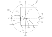
- FIG. 3 is a diagram showing a schematic configuration of the communication unit 12, and is a schematic diagram of the housing 17 as viewed from the rear surface 17A side.
- FIG. 4 is a diagram showing a schematic configuration of the communication unit 12, and is a schematic diagram of the housing 17 as viewed from the top surface 17B side.
- FIG. 5 is a diagram of the housing 17 of the sphygmomanometer 10 as viewed from the side surface 17C on which the information display unit 17E is provided.
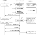
- FIG. 6 is a sequence chart for explaining a pairing method between the sphygmomanometer 10 and the smartphone 20.
- the measurement device of the technology disclosed herein includes a short-range wireless communication unit that communicates by a communication method (e.g., Bluetooth (registered trademark)) that allows pairing, a processor, and a housing that accommodates the processor and the short-range wireless communication unit, and the antenna of the short-range wireless communication unit has a directivity in a first direction that is greater than and is greatest than a directivity in a second direction other than the first direction, and an information display unit that can acquire first information by imaging is provided in an area on the outer surface of the housing that includes an intersection with a virtual line extending from the antenna in the first direction, and the processor starts processing required for pairing when it receives a signal including information based on the first information and the received radio wave intensity of the signal is equal to or greater than a threshold.
- a communication method e.g., Bluetooth (registered trademark)
- the antenna of the short-range wireless communication unit has a directivity in a first direction that is greater than and is greatest than a directivity in a second direction other
- the information terminal when pairing is performed between an information terminal and a measurement device, the information terminal is used to image the information display unit to acquire the first information, and a signal including the information based on the first information is transmitted from the information terminal to the measurement device, so that the signal from the information terminal is received by the measurement device when the information terminal is located in a direction in which the antenna has a high directivity and in a position close to the measurement device.
- the received radio wave strength of the signal becomes sufficiently large in the measuring device, so that the information terminal that sent the signal can be identified as the pairing partner.
- an information terminal that is close to the measuring device and in a position where information can be obtained from the information display unit can be identified as the pairing partner, so that pairing with the intended information terminal can be realized.
- FIG. 1 is a schematic diagram showing a schematic configuration of a management system 100.
- the management system 100 includes a blood pressure monitor 10, which is an example of a measurement device, and a smartphone 20, which is an example of an information terminal, and is a system for managing measurement data and programs of the blood pressure monitor 10 using the smartphone 20.
- the blood pressure monitor 10 and the smartphone 20 are configured to be able to communicate with each other via short-range wireless communication.
- a method that allows pairing can be adopted as the method of short-range wireless communication.
- the method of short-range wireless communication will be described as Bluetooth (registered trademark).
- An owner of both the blood pressure monitor 10 and the smartphone 20 will be referred to as a user in the following.
- the sphygmomanometer 10 includes a processor 11 , a communication unit 12 , a memory unit 13 , an operation unit 14 , a display unit 15 , and a sensor unit 16 .
- the sensor unit 16 is equipped with a pressure sensor placed in the cuff portion of the blood pressure monitor 10 as a measurement sensor, and this pressure sensor detects the pulse wave from the user's blood vessel under the appropriate cuff pressure.
- the blood pressure monitor 10 can calculate blood pressure information including the systolic blood pressure, diastolic blood pressure, and pulse rate based on the pulse wave detected by the sensor unit 16.
- the communication unit 12 is a communication interface for short-range wireless communication, and includes a communication antenna and various circuits.
- the storage unit 13 includes a work memory such as a RAM (Random Access Memory) as well as a non-transitory storage medium such as a flash memory.
- This storage medium stores various information such as measured blood pressure information.
- the operation unit 14 is an input means such as a button or a touch panel that accepts input from the user, and accepts various operations from the user, such as turning the power on/off, starting the measurement of blood pressure information, and selecting items.
- the operation unit 14 includes a measurement start button 14A for instructing the start of blood pressure information measurement, and a communication button 14B for activating the communication unit 12 (enabling short-range wireless communication).
- the measurement start button 14A and the communication button 14B may be hardware buttons, or may be software buttons displayed on the display unit 15 equipped with a touch panel.
- the display unit 15 is configured with a display such as an organic EL (electroluminescence) display or a liquid crystal display, and displays the measured blood pressure information, etc.
- a display such as an organic EL (electroluminescence) display or a liquid crystal display, and displays the measured blood pressure information, etc.
- the processor 11 controls each part of the blood pressure monitor 10.
- the processor 11 is a CPU (Central Processing Unit), which is a general-purpose processor that executes software (programs) and performs various functions, a programmable logic device (PLD), which is a processor whose circuit configuration can be changed after manufacture such as an FPGA (Field Programmable Gate Array), or a dedicated electric circuit, which is a processor having a circuit configuration designed specifically to execute a specific process such as an ASIC (Application Specific Integrated Circuit).
- the processor 11 may be composed of one processor, or may be composed of a combination of two or more processors of the same or different types (for example, multiple FPGAs, or a combination of a CPU and an FPGA). More specifically, the hardware structure of the processor 11 is an electrical circuit that combines circuit elements such as semiconductor elements.
- the processor 11 When the processor 11 detects pressing of the measurement start button 14A included in the operation unit 14, it accepts an instruction to start measurement, supplies air to the cuff, and calculates blood pressure information based on the pulse wave detected by the sensor unit 16 under appropriate cuff pressure. The processor 11 then causes the display unit 15 to display the calculated blood pressure information.
- the processor 11 controls each component of the sphygmomanometer 10 to execute processing according to the user's operation performed via the operation unit 14.
- the act of pressing the measurement start button 14A constitutes an operation to start the operation of the sensor unit 16.
- the measurement start button 14A can be input to the processor 11 by simply pressing it once in a short period of time (performing a so-called short press operation) rather than continuing to press it for a predetermined period of time (performing a so-called long press operation).
- the processor 11 When the processor 11 detects a press of the communication button 14B included in the operation unit 14, it starts the communication unit 12.
- the pressing operation of the communication button 14B required to start the communication unit 12 is, for example, a short press operation.
- the blood pressure monitor 10 can be replaced with a weight scale, a body composition monitor, a pulse monitor, a heart rate monitor, a thermometer, a blood glucose meter, a pulse oximeter, an activity monitor, or the like.
- the sensor unit 16 includes various measuring sensors (pressure sensor, pulse wave sensor, blood glucose sensor, photoelectric sensor, temperature sensor, acceleration sensor, etc.) for measuring the physical quantity of the measurement target.
- the processor 11 upon detecting the pressing of the measurement start button 14A included in the operation unit 14, activates the measuring sensor (pressure sensor, pulse wave sensor, blood glucose sensor, photoelectric sensor, temperature sensor, etc.) included in the sensor unit 16 to measure the bioinformation.
- the processor 11 upon detecting the pressing of the power button for turning on the device instead of the measurement start button 14A, activates the measuring sensor (acceleration sensor or angular velocity sensor, etc.) included in the sensor unit 16 to measure the activity amount.
- the smartphone 20 includes a processor 21 , a communication unit 22 , a storage unit 23 , an operation unit 24 , a display unit 25 , and an imaging unit 26 .
- the communication unit 22 is a communication interface for short-range wireless communication, and includes a communication antenna and various circuits.
- the storage unit 23 includes a work memory such as RAM, as well as a non-transitory storage medium such as a flash memory.
- This storage medium stores various types of information, including application programs (operation programs for the information terminal, management applications described below).
- the operation unit 24 is an input means such as a button or a touch panel that accepts input from the user, and accepts various operations from the user.
- the display unit 25 is composed of a display such as an organic EL display or a liquid crystal display.
- the imaging unit 26 includes an imaging element and an image processing unit, and captures an image of a subject using the imaging element to generate captured image data.
- Processor 21 controls each part of smartphone 20. Like processor 11, processor 21 is composed of one or more processors. Processor 21 executes various programs stored in storage unit 23 to perform processing according to these programs.
- FIG. 2 is a schematic diagram showing an example of the external configuration of the blood pressure monitor 10 shown in FIG. 1.
- the blood pressure monitor 10 includes a housing 17 that houses at least the processor 11, the communication unit 12, and the memory unit 13 shown in FIG. 1, a cuff 19 that can be wrapped around the user's measurement site (e.g., the upper arm), and an air tube 18 that connects the housing 17 and the cuff 19.
- the housing 17 is a five-sided shape, and is placed on a placement surface such as a desk or floor when the sphygmomanometer 10 is in use (when blood pressure information is measured).
- the outer surface of the housing 17 has a bottom surface 17D that faces the placement surface when the sphygmomanometer 10 is in use, a top surface 17B that forms a predetermined angle with the bottom surface 17D, a pair of side surfaces 17C that are approximately perpendicular to the bottom surface 17D, and a back surface 17A.
- the top surface 17B is provided with a display unit 15 and an operation unit 14.
- the information display section 17E is an area on which text such as numbers, letters, or symbols representing the first information, or a code image such as a one-dimensional code or a two-dimensional code representing the first information, is printed or affixed with an affixing member such as a sticker.
- the first information is information unique to the sphygmomanometer 10, such as address information of the communication section 12 or individual identification information (such as a serial number) of the sphygmomanometer 10.
- the first information may be numbers, letters, or symbols randomly generated for each sphygmomanometer 10.
- the first information is also stored in the memory section 13.
- a management application for managing blood pressure information is pre-installed and stored in the memory unit 23 of the smartphone 20.
- This management application processes captured image data obtained by capturing an image of the information display unit 17E using the imaging unit 26 of the smartphone 20, and is capable of recognizing text included in the portion of the information display unit 17E in the captured image data to obtain the first information, or decoding a code image in the portion of the information display unit 17E in the captured image data to obtain the first information.
- FIG. 3 is a diagram showing the general configuration of the communication unit 12, and is a schematic diagram of the housing 17 as viewed from the rear surface 17A side.
- FIG. 4 is a diagram showing the general configuration of the communication unit 12, and is a schematic diagram of the housing 17 as viewed from the top surface 17B side.
- the display unit 15 and the operation unit 14 are omitted.
- the communication unit 12 is configured such that an antenna 12A is formed as a conductor pattern on the surface of a flat substrate 12B.
- the antenna 12A is configured as a Yagi antenna pattern.
- the surface of the substrate 12B of the communication unit 12 is parallel to the bottom surface 17D.
- a virtual axis LZ passing through the power supply unit of the antenna 12A and perpendicular to the surface of the substrate 12B, a virtual axis LX passing through the power supply unit of the antenna 12A and parallel to the surface of the substrate 12B, and a virtual circle LC1 centered on the power supply unit of the antenna 12A are shown.
- a virtual axis LY perpendicular to the virtual axis LX and the virtual axis LZ and passing through the power supply unit of the antenna 12A, and a virtual circle LC2 centered on the power supply unit of the antenna 12A are shown.
- the radiation characteristics of the antenna 12A are represented by a radiation pattern DB1 in a plane including the virtual axis LX and the virtual axis LZ shown in FIG. 3, and a radiation pattern DB2 in a plane including the virtual axis LX and the virtual axis LY shown in FIG. 4.
- the radiation patterns DB1 and DB2 are shown diagrammatically. Virtual circles LC1 and LC2 each indicate the position where the directivity (gain) is maximum.
- the angle between a line connecting the power feed point of antenna 12A and a point on imaginary circle LC1 and the portion of imaginary axis LZ above the power feed point is defined as the direction relative to antenna 12A.
- the angle between a line connecting the power feed point of antenna 12A and a point on imaginary circle LC2 and the portion of imaginary axis LY above the power feed point is defined as the direction relative to antenna 12A.
- antenna 12A has a directivity in a 90° direction (first direction) that is greater than the directivity in directions other than 90° (second direction), and is maximum in all directions.
- Antenna 12A has directivity in the direction of a main beam width of 90° and in nearby directions (e.g., directions at angles from 60° to 120°) that is greater than the directivity in all directions other than these directions by a threshold value or more (e.g., more than twice as much). In other words, antenna 12A has strong directivity in the first direction.
- the user turns on the power supply of the blood pressure monitor 10 and operates the smartphone 20 to start the management app.
- the processor 11 of the started blood pressure monitor 10 starts scanning by the communication unit 12 (step S11). Scanning means that the communication unit 12 goes into a receiving state and acquires information about nearby devices.
- the processor 21 of the smartphone 20 displays a device registration screen on the display unit 25 (step S1).
- the processor 21 of the smartphone 20 displays information instructing the display unit 25 to take an image of the information display unit 17E of the blood pressure monitor 10, including the device registration screen.
- the processor 21 also starts scanning by the communication unit 22.
- step S5 the processor 21 of the smartphone 20 controls the display unit 25 to display a live view of the image captured by the imaging unit 26.
- step S5 the processor 21 of the smartphone 20 causes the display unit 25 to display information indicating the progress of pairing (step S5).
- the display unit 25 displays a message such as "Pairing with the blood pressure monitor. Please hold your smartphone in the same position and wait.”
- the processor 11 of the sphygmomanometer 10 When the processor 11 of the sphygmomanometer 10 receives a broadcast signal transmitted from the smartphone 20 in the process of step S4, if the broadcast signal contains the same first information as that stored in the memory unit 13 and the reception strength of the broadcast signal is equal to or greater than a threshold, the processor 11 stops scanning by the communication unit 12 (step S12) and transitions to pairing mode (step S13).
- the pairing mode is a mode in which a process for sharing encrypted information with an information terminal for performing encrypted communication via short-range wireless communication can be executed.
- the sphygmomanometer 10 can be paired with the information terminal only when it is operating in this pairing mode. If the received broadcast signal does not contain the same information as that stored in the memory unit 13 or if the reception strength is less than a threshold, the processor 11 of the sphygmomanometer 10 continues scanning without transitioning to pairing mode.
- the smartphone 20 When the processes from step S2 to step S4 are being performed, the smartphone 20 is positioned almost opposite the side surface 17C of the blood pressure monitor 10, and is positioned close enough to the information display unit 17E that the first information can be obtained from the information display unit 17E. In other words, the smartphone 20 is positioned in a range where the communication unit 12 of the blood pressure monitor 10 has a strong directivity. Therefore, even in this embodiment where the antenna 12A of the communication unit 12 has directivity, by capturing an image of the information display unit 17E with the smartphone 20 and maintaining that state, it is possible to transition the blood pressure monitor 10 to the pairing mode without performing any special operations on the blood pressure monitor 10.
- the smartphone 20 can be more accurately guided to a range with strong directivity of the communication unit 12, and the blood pressure monitor 10 can be more reliably switched to the pairing mode.
- the distance between the information display unit 17E and the smartphone 20 (in other words, the distance between the communication unit 12 and the smartphone 20) when reading the first information from the information display unit 17E can be sufficiently small.
- the smartphone 20 located near the blood pressure monitor 10 can more reliably switch the blood pressure monitor 10 to the pairing mode.
- step S14 When the processor 11 of the blood pressure monitor 10 transitions to the pairing mode, it starts advertising by the communication unit 12 (step S14).
- step S14 a packet including information required for establishing a communication connection by short-range wireless communication (e.g., individual identification information of the blood pressure monitor 10, etc.) is periodically broadcast. This information may be shared with the first information.
- the processor 21 of the smartphone 20 acquires the broadcast signal transmitted from the sphygmomanometer 10 in the processing of step S14, if the reception strength of this broadcast signal is equal to or greater than a threshold, it makes a connection request to the sphygmomanometer 10 via the communication unit 22.
- the processor 11 of the sphygmomanometer 10 responds to this connection request via the communication unit 12, a communication connection is established between the sphygmomanometer 10 and the smartphone 20 by short-range wireless communication (step S20).
- the sphygmomanometer 10 and the smartphone 20 are in close proximity to each other, so a connection between them is established in step S20.
- step S2 to step S5 and step S12 to step S14 are being performed, the smartphone 20 is in a position where it can capture an image of the information display unit 17E. Therefore, the smartphone 20 is located in a range where the communication unit 12 of the blood pressure monitor 10 has a strong directivity. Therefore, even in this embodiment where the antenna 12A of the communication unit 12 has directivity, stable communication between the blood pressure monitor 10 and the smartphone 20 is possible.
- step S21 When a communication connection between the smartphone 20 and the blood pressure monitor 10 is established, mutual authentication between the smartphone 20 and the blood pressure monitor 10 is performed by a predetermined method, and when the mutual authentication is completed, encryption information (e.g., an encryption key, etc.) for performing encrypted communication by short-range wireless communication is shared between the smartphone 20 and the blood pressure monitor 10 (step S21). Sharing of encrypted information means that the processor 11 of the blood pressure monitor 10 generates encryption information, stores the encryption information in the storage unit 13 and transmits the encryption information to the smartphone 20, and the smartphone 20 stores the encryption information in the storage unit 23. Note that encryption information may also be shared by the processor 21 of the smartphone 20 generating encryption information, storing the encryption information in the storage unit 23 and transmitting the encryption information to the blood pressure monitor 10, and the blood pressure monitor 10 storing the encryption information in the storage unit 13.
- encryption information e.g., an encryption key, etc.
- the processor 21 of the smartphone 20 causes the display unit 25 to display, for example, a message indicating that pairing has been completed.
- the processor 21 of the smartphone 20 then disconnects the communication connection with the blood pressure monitor 10. Thereafter, secure communication using encrypted information is possible between the smartphone 20 and the blood pressure monitor 10. For example, when the measurement start button 14A is pressed with the cuff wrapped around the arm or wrist, blood pressure information is derived and stored in the memory unit 13.
- the processor 11 of the blood pressure monitor 10 then starts the communication unit 12, establishes a connection with the smartphone 20 with which the encrypted information has been shared, encrypts the blood pressure information, and transmits it to the smartphone 20.
- the processor 11 of the blood pressure monitor 10 preferably sets the radio wave strength of the communication unit 12 to a first strength before the transition to the pairing mode in step S13, and sets the radio wave strength of the communication unit 12 to a second strength lower than the first strength after the transition to the pairing mode.
- the radio wave strength from the blood pressure monitor 10 will be weak at that other information terminal, and it is possible to prevent a connection from being established between the other information terminal and the blood pressure monitor 10. This makes it possible to realize pairing with the intended smartphone 20 located near the blood pressure monitor 10.
- the smartphone 20 that is capable of capturing an image of the information display unit 17E near the blood pressure monitor 10 can transition the blood pressure monitor 10 to a state in which pairing is possible. This makes it possible to prevent the blood pressure monitor 10 from being paired with an unintended information terminal located far away from the blood pressure monitor 10.
- the information display unit 17E is configured by a print area or an adhesive member, but is not limited thereto.
- the display unit 15 can also function as the information display unit 17E.
- the processor 11 displays the first information (text or code image) in a partial range of the display unit 15.
- the above-mentioned virtual line of the antenna 12A of the communication unit 12 is arranged so as to intersect in the above-mentioned range of the display unit 15 on the upper surface 17B.
- the blood pressure monitor 10 transitions to a pairing mode, and pairing is performed between the blood pressure monitor 10 and the smartphone 20.
- the first information can be displayed as long as the display unit 15 is operating, so that the first information can be prevented from being lost.
- antenna 12A configured with a Yagi antenna pattern
- other patterns can also be used as long as the antenna has a radiation pattern with strong directivity in a specific direction.
Landscapes
- Engineering & Computer Science (AREA)
- Health & Medical Sciences (AREA)
- Life Sciences & Earth Sciences (AREA)
- Computer Networks & Wireless Communication (AREA)
- Signal Processing (AREA)
- Physics & Mathematics (AREA)
- Public Health (AREA)
- Biomedical Technology (AREA)
- Heart & Thoracic Surgery (AREA)
- Medical Informatics (AREA)
- Molecular Biology (AREA)
- Surgery (AREA)
- Animal Behavior & Ethology (AREA)
- General Health & Medical Sciences (AREA)
- Pathology (AREA)
- Veterinary Medicine (AREA)
- Biophysics (AREA)
- Computer Security & Cryptography (AREA)
- Vascular Medicine (AREA)
- Cardiology (AREA)
- Quality & Reliability (AREA)
- Ophthalmology & Optometry (AREA)
- Physiology (AREA)
- Electromagnetism (AREA)
- Databases & Information Systems (AREA)
- Measuring Pulse, Heart Rate, Blood Pressure Or Blood Flow (AREA)
- Measuring And Recording Apparatus For Diagnosis (AREA)
- Mobile Radio Communication Systems (AREA)
Abstract
Description
ペアリングが可能な通信方式による通信を行う近距離無線通信部(通信部12)と、
プロセッサ(プロセッサ11)と、
上記プロセッサ及び上記近距離無線通信部を収容する筐体(筐体17)と、を備え、
上記近距離無線通信部のアンテナ(アンテナ12A)は、第1方向への指向性が上記第1方向以外の第2方向への指向性よりも大きく且つ最大となっており、
上記筐体の外面における、上記アンテナから上記第1方向へ延びる仮想線との交点(交点P)を含む面(側面17C)には、撮像によって第1情報を取得可能な情報表示部(情報表示部17E)が設けられ、
上記プロセッサは、上記第1情報に基づく情報を含む信号を受信し且つ上記信号の受信強度が閾値以上の場合に、ペアリングに必要な処理を開始する、測定装置(血圧計10)。
(1)に記載の測定装置であって、
上記プロセッサは、上記信号を受信し且つ上記信号の受信強度が上記閾値以上の場合に、近距離無線通信による通信の接続確立に必要な情報を含むブロードキャスト信号の送信を開始し(ステップS14)、そのブロードキャスト信号に応答した情報端末と接続確立し(ステップS20)、ペアリングを行う測定装置。
(2)に記載の測定装置であって、
上記プロセッサは、上記信号を受信し且つ上記信号の受信強度が上記閾値以上の場合に、上記アンテナの電波強度を、上記信号の受信より前のタイミングにおける電波強度よりも低下させる、測定装置。
(1)から(3)のいずれかに記載の測定装置であって、
上記情報表示部は、上記第1情報を表示可能なディスプレイ(表示部15)であり、
上記ディスプレイには測定結果が表示可能に構成される測定装置。
本開示の技術の測定装置は、ペアリングが可能な通信方式(例えばBluetooth(登録商標))による通信を行う近距離無線通信部と、プロセッサと、前記プロセッサ及び前記近距離無線通信部を収容する筐体と、を備え、前記近距離無線通信部のアンテナは、第1方向への指向性が前記第1方向以外の第2方向への指向性よりも大きく且つ最大となっており、前記筐体の外面における、前記アンテナから前記第1方向へ延びる仮想線との交点を含む領域には、撮像によって第1情報を取得可能な情報表示部が設けられ、前記プロセッサは、前記第1情報に基づく情報を含む信号を受信し且つ前記信号の受信電波強度が閾値以上の場合に、ペアリングに必要な処理を開始する、ものである。この構成によれば、情報端末と測定装置の間でペアリングを行う際には、情報端末を用いて情報表示部を撮像して第1情報を取得し、その第1情報に基づく情報を含む信号を情報端末から測定装置に送信することで、アンテナの指向性が高い方向且つ測定装置と近い位置に情報端末が位置した状態で、その情報端末からの信号が測定装置で受信される。この結果、測定装置において、信号の受信電波強度は十分に大きくなるため、その信号の送信元の情報端末をペアリング相手として特定することができる。このように、測定装置の近くにあり且つ情報表示部から情報を取得可能な位置にある情報端末をペアリング相手として特定できるため、意図した情報端末との間でのペアリングを実現することができる。
図1は、管理システム100の概略構成を示す模式図である。管理システム100は、測定装置の一例である血圧計10と、情報端末の一例であるスマートフォン20と、を備え、血圧計10の測定データやプログラム等をスマートフォン20で管理するためのシステムである。血圧計10とスマートフォン20は近距離無線通信によって通信可能な構成となっている。近距離無線通信の方式は、ペアリングが可能な方式を採用することができる。以下では、近距離無線通信の方式をBluetooth(登録商標)として説明する。血圧計10とスマートフォン20を共に所有する所有者のことを以下ではユーザと記載する。
血圧計10は、プロセッサ11と、通信部12と、記憶部13と、操作部14と、表示部15と、センサ部16と、を備える。
スマートフォン20は、プロセッサ21と、通信部22と、記憶部23と、操作部24と、表示部25と、撮像部26と、を備える。
次に、血圧計10とスマートフォン20のペアリング方法について説明する。図6は、血圧計10とスマートフォン20のペアリング方法を説明するためのシーケンスチャートである。
11,21 プロセッサ
12,22 通信部
12A アンテナ
12B 基板
13,23 記憶部
14,24 操作部
14A 測定開始ボタン
14B 通信ボタン
15,25 表示部
16 センサ部
17 筐体
17A 背面
17B 上面
17C 側面
17D 底面
17E 情報表示部
18 エアチューブ
19 カフ
20 スマートフォン
26 撮像部
100 管理システム
LC1,LC2 仮想円
DB1,DB2 放射パターン
Claims (4)
- ペアリングが可能な通信方式による通信を行う近距離無線通信部と、
プロセッサと、
前記プロセッサ及び前記近距離無線通信部を収容する筐体と、を備え、
前記近距離無線通信部のアンテナは、第1方向への指向性が前記第1方向以外の第2方向への指向性よりも大きく且つ最大となっており、
前記筐体の外面における、前記アンテナから前記第1方向へ延びる仮想線との交点を含む面には、撮像によって第1情報を取得可能な情報表示部が設けられ、
前記プロセッサは、前記第1情報に基づく情報を含む信号を受信し且つ前記信号の受信強度が閾値以上の場合に、ペアリングに必要な処理を開始する、測定装置。 - 請求項1に記載の測定装置であって、
前記プロセッサは、前記信号を受信し且つ前記信号の受信強度が前記閾値以上の場合に、近距離無線通信による通信の接続確立に必要な情報を含むブロードキャスト信号の送信を開始し、当該ブロードキャスト信号に応答した情報端末と接続確立し、ペアリングを行う測定装置。 - 請求項2に記載の測定装置であって、
前記プロセッサは、前記信号を受信し且つ前記信号の受信強度が前記閾値以上の場合に、前記アンテナの電波強度を、前記信号の受信より前のタイミングにおける電波強度よりも低下させる、測定装置。 - 請求項1から3のいずれか1項に記載の測定装置であって、
前記情報表示部は、前記第1情報を表示可能なディスプレイであり、
前記ディスプレイには測定結果が表示可能に構成される測定装置。
Priority Applications (3)
| Application Number | Priority Date | Filing Date | Title |
|---|---|---|---|
| DE112024000829.1T DE112024000829T5 (de) | 2023-06-07 | 2024-01-12 | Messvorrichtung |
| CN202480025335.0A CN121080113A (zh) | 2023-06-07 | 2024-01-12 | 测定装置 |
| US19/363,159 US20260046958A1 (en) | 2023-06-07 | 2025-10-20 | Measuring device |
Applications Claiming Priority (2)
| Application Number | Priority Date | Filing Date | Title |
|---|---|---|---|
| JP2023093953A JP2024175876A (ja) | 2023-06-07 | 2023-06-07 | 測定装置 |
| JP2023-093953 | 2023-06-07 |
Related Child Applications (1)
| Application Number | Title | Priority Date | Filing Date |
|---|---|---|---|
| US19/363,159 Continuation US20260046958A1 (en) | 2023-06-07 | 2025-10-20 | Measuring device |
Publications (1)
| Publication Number | Publication Date |
|---|---|
| WO2024252711A1 true WO2024252711A1 (ja) | 2024-12-12 |
Family
ID=93795810
Family Applications (1)
| Application Number | Title | Priority Date | Filing Date |
|---|---|---|---|
| PCT/JP2024/000653 Ceased WO2024252711A1 (ja) | 2023-06-07 | 2024-01-12 | 測定装置 |
Country Status (5)
| Country | Link |
|---|---|
| US (1) | US20260046958A1 (ja) |
| JP (1) | JP2024175876A (ja) |
| CN (1) | CN121080113A (ja) |
| DE (1) | DE112024000829T5 (ja) |
| WO (1) | WO2024252711A1 (ja) |
Citations (4)
| Publication number | Priority date | Publication date | Assignee | Title |
|---|---|---|---|---|
| JP2003018070A (ja) * | 2001-06-28 | 2003-01-17 | Matsushita Electric Ind Co Ltd | 被撮影者に映像を送信するシステム |
| JP2003218785A (ja) * | 2002-01-22 | 2003-07-31 | Sony Corp | 無線通信装置、通信相手探索方法、および通信相手探索プログラム |
| JP2014216723A (ja) * | 2013-04-23 | 2014-11-17 | 日本電信電話株式会社 | 無線通信装置およびペアリング方法 |
| JP2020156600A (ja) * | 2019-03-25 | 2020-10-01 | オムロンヘルスケア株式会社 | 生体情報測定装置、端末、及び生体情報測定システム |
-
2023
- 2023-06-07 JP JP2023093953A patent/JP2024175876A/ja active Pending
-
2024
- 2024-01-12 WO PCT/JP2024/000653 patent/WO2024252711A1/ja not_active Ceased
- 2024-01-12 DE DE112024000829.1T patent/DE112024000829T5/de active Pending
- 2024-01-12 CN CN202480025335.0A patent/CN121080113A/zh active Pending
-
2025
- 2025-10-20 US US19/363,159 patent/US20260046958A1/en active Pending
Patent Citations (4)
| Publication number | Priority date | Publication date | Assignee | Title |
|---|---|---|---|---|
| JP2003018070A (ja) * | 2001-06-28 | 2003-01-17 | Matsushita Electric Ind Co Ltd | 被撮影者に映像を送信するシステム |
| JP2003218785A (ja) * | 2002-01-22 | 2003-07-31 | Sony Corp | 無線通信装置、通信相手探索方法、および通信相手探索プログラム |
| JP2014216723A (ja) * | 2013-04-23 | 2014-11-17 | 日本電信電話株式会社 | 無線通信装置およびペアリング方法 |
| JP2020156600A (ja) * | 2019-03-25 | 2020-10-01 | オムロンヘルスケア株式会社 | 生体情報測定装置、端末、及び生体情報測定システム |
Also Published As
| Publication number | Publication date |
|---|---|
| DE112024000829T5 (de) | 2025-12-04 |
| JP2024175876A (ja) | 2024-12-19 |
| US20260046958A1 (en) | 2026-02-12 |
| CN121080113A (zh) | 2025-12-05 |
Similar Documents
| Publication | Publication Date | Title |
|---|---|---|
| ES2738671T3 (es) | Método para el control de desbloqueo de terminal y terminal correspondiente | |
| WO2015120726A1 (zh) | 可控制显示位置的便携式终端及其显示方法 | |
| US20250166816A1 (en) | Measurement device, information terminal, and operation recording medium for information terminal | |
| CN114711734B (zh) | 测量生理参数的方法及电子设备 | |
| WO2021031979A1 (zh) | 生理参数的采集方法和装置与生理参数的处理方法和装置 | |
| WO2015120762A1 (zh) | 一种生理参数测量系统 | |
| US20230157561A1 (en) | Electronic device comprising ultrasonic device and ppg signal acquisition method thereof | |
| US9699595B2 (en) | Method and wearable device for interworking with a portable terminal | |
| JP2025535750A (ja) | ディスプレイインターフェイスを備えた超音波スキャナ | |
| JP2024175876A (ja) | 測定装置 | |
| CN117897089A (zh) | 电子装置以及由电子装置检测震颤症状的方法 | |
| US12634684B2 (en) | Measurement device | |
| WO2024062677A1 (ja) | 測定装置、情報端末、及び情報端末の作動プログラム | |
| JP2024044700A (ja) | 測定装置、情報端末、及び情報端末の作動プログラム | |
| US12178544B2 (en) | Information management system, and pairing method for measurement device and information terminal | |
| US11483126B2 (en) | Physiological information system, physiological information sensor and physiological information processing apparatus | |
| JP2024014385A (ja) | 管理システム、測定装置、情報端末、及び情報端末の作動プログラム | |
| US20250049395A1 (en) | Apparatus, system, and method for remote vital sign collection | |
| KR20210139045A (ko) | 데이터 전송 방법 및 이를 지원하는 전자 장치 | |
| KR20160033935A (ko) | 웨어러블 단말기 | |
| JP2024030347A (ja) | 管理システム、測定装置、情報端末、及び情報端末の作動プログラム | |
| US12376752B2 (en) | Apparatus for measuring bio-information, and electronic device including the same | |
| CN121463913A (zh) | 用于测量心跳的方法和电子装置以及存储介质 | |
| JP2018109922A (ja) | 認証装置および認証システム | |
| WO2024252715A1 (ja) | 情報端末、制御方法、及び制御プログラム |
Legal Events
| Date | Code | Title | Description |
|---|---|---|---|
| 121 | Ep: the epo has been informed by wipo that ep was designated in this application |
Ref document number: 24818953 Country of ref document: EP Kind code of ref document: A1 |
|
| WWE | Wipo information: entry into national phase |
Ref document number: 202517092265 Country of ref document: IN |
|
| WWE | Wipo information: entry into national phase |
Ref document number: 112024000829 Country of ref document: DE |
|
| WWP | Wipo information: published in national office |
Ref document number: 202517092265 Country of ref document: IN |
|
| WWE | Wipo information: entry into national phase |
Ref document number: CN2024800253350 Country of ref document: CN |
|
| WWP | Wipo information: published in national office |
Ref document number: 112024000829 Country of ref document: DE |
|
| 122 | Ep: pct application non-entry in european phase |
Ref document number: 24818953 Country of ref document: EP Kind code of ref document: A1 |