WO2024252645A1 - 工具マガジン - Google Patents
工具マガジン Download PDFInfo
- Publication number
- WO2024252645A1 WO2024252645A1 PCT/JP2023/021435 JP2023021435W WO2024252645A1 WO 2024252645 A1 WO2024252645 A1 WO 2024252645A1 JP 2023021435 W JP2023021435 W JP 2023021435W WO 2024252645 A1 WO2024252645 A1 WO 2024252645A1
- Authority
- WO
- WIPO (PCT)
- Prior art keywords
- tool
- arm
- pot
- rotation
- gripping
- Prior art date
- Legal status (The legal status is an assumption and is not a legal conclusion. Google has not performed a legal analysis and makes no representation as to the accuracy of the status listed.)
- Ceased
Links
Images










Classifications
-
- B—PERFORMING OPERATIONS; TRANSPORTING
- B23—MACHINE TOOLS; METAL-WORKING NOT OTHERWISE PROVIDED FOR
- B23Q—DETAILS, COMPONENTS, OR ACCESSORIES FOR MACHINE TOOLS, e.g. ARRANGEMENTS FOR COPYING OR CONTROLLING; MACHINE TOOLS IN GENERAL CHARACTERISED BY THE CONSTRUCTION OF PARTICULAR DETAILS OR COMPONENTS; COMBINATIONS OR ASSOCIATIONS OF METAL-WORKING MACHINES, NOT DIRECTED TO A PARTICULAR RESULT
- B23Q3/00—Devices holding, supporting, or positioning work or tools, of a kind normally removable from the machine
- B23Q3/155—Arrangements for automatic insertion or removal of tools, e.g. combined with manual handling
- B23Q3/157—Arrangements for automatic insertion or removal of tools, e.g. combined with manual handling of rotary tools
- B23Q3/15713—Arrangements for automatic insertion or removal of tools, e.g. combined with manual handling of rotary tools a transfer device taking a single tool from a storage device and inserting it in a spindle
- B23Q3/1572—Arrangements for automatic insertion or removal of tools, e.g. combined with manual handling of rotary tools a transfer device taking a single tool from a storage device and inserting it in a spindle the storage device comprising rotating or circulating storing means
- B23Q3/15722—Rotary discs or drums
-
- B—PERFORMING OPERATIONS; TRANSPORTING
- B23—MACHINE TOOLS; METAL-WORKING NOT OTHERWISE PROVIDED FOR
- B23Q—DETAILS, COMPONENTS, OR ACCESSORIES FOR MACHINE TOOLS, e.g. ARRANGEMENTS FOR COPYING OR CONTROLLING; MACHINE TOOLS IN GENERAL CHARACTERISED BY THE CONSTRUCTION OF PARTICULAR DETAILS OR COMPONENTS; COMBINATIONS OR ASSOCIATIONS OF METAL-WORKING MACHINES, NOT DIRECTED TO A PARTICULAR RESULT
- B23Q3/00—Devices holding, supporting, or positioning work or tools, of a kind normally removable from the machine
- B23Q3/155—Arrangements for automatic insertion or removal of tools, e.g. combined with manual handling
- B23Q3/157—Arrangements for automatic insertion or removal of tools, e.g. combined with manual handling of rotary tools
-
- B—PERFORMING OPERATIONS; TRANSPORTING
- B23—MACHINE TOOLS; METAL-WORKING NOT OTHERWISE PROVIDED FOR
- B23Q—DETAILS, COMPONENTS, OR ACCESSORIES FOR MACHINE TOOLS, e.g. ARRANGEMENTS FOR COPYING OR CONTROLLING; MACHINE TOOLS IN GENERAL CHARACTERISED BY THE CONSTRUCTION OF PARTICULAR DETAILS OR COMPONENTS; COMBINATIONS OR ASSOCIATIONS OF METAL-WORKING MACHINES, NOT DIRECTED TO A PARTICULAR RESULT
- B23Q3/00—Devices holding, supporting, or positioning work or tools, of a kind normally removable from the machine
- B23Q3/155—Arrangements for automatic insertion or removal of tools, e.g. combined with manual handling
- B23Q3/1552—Arrangements for automatic insertion or removal of tools, e.g. combined with manual handling parts of devices for automatically inserting or removing tools
- B23Q3/1554—Transfer mechanisms, e.g. tool gripping arms; Drive mechanisms therefore
-
- B—PERFORMING OPERATIONS; TRANSPORTING
- B23—MACHINE TOOLS; METAL-WORKING NOT OTHERWISE PROVIDED FOR
- B23Q—DETAILS, COMPONENTS, OR ACCESSORIES FOR MACHINE TOOLS, e.g. ARRANGEMENTS FOR COPYING OR CONTROLLING; MACHINE TOOLS IN GENERAL CHARACTERISED BY THE CONSTRUCTION OF PARTICULAR DETAILS OR COMPONENTS; COMBINATIONS OR ASSOCIATIONS OF METAL-WORKING MACHINES, NOT DIRECTED TO A PARTICULAR RESULT
- B23Q3/00—Devices holding, supporting, or positioning work or tools, of a kind normally removable from the machine
- B23Q3/155—Arrangements for automatic insertion or removal of tools, e.g. combined with manual handling
- B23Q3/157—Arrangements for automatic insertion or removal of tools, e.g. combined with manual handling of rotary tools
- B23Q3/15773—Arrangements for automatic insertion or removal of tools, e.g. combined with manual handling of rotary tools a transfer device taking the tool from a storage device and passing it on to other transfer devices, which insert it in a spindle
-
- B—PERFORMING OPERATIONS; TRANSPORTING
- B23—MACHINE TOOLS; METAL-WORKING NOT OTHERWISE PROVIDED FOR
- B23Q—DETAILS, COMPONENTS, OR ACCESSORIES FOR MACHINE TOOLS, e.g. ARRANGEMENTS FOR COPYING OR CONTROLLING; MACHINE TOOLS IN GENERAL CHARACTERISED BY THE CONSTRUCTION OF PARTICULAR DETAILS OR COMPONENTS; COMBINATIONS OR ASSOCIATIONS OF METAL-WORKING MACHINES, NOT DIRECTED TO A PARTICULAR RESULT
- B23Q3/00—Devices holding, supporting, or positioning work or tools, of a kind normally removable from the machine
- B23Q3/155—Arrangements for automatic insertion or removal of tools, e.g. combined with manual handling
- B23Q3/1552—Arrangements for automatic insertion or removal of tools, e.g. combined with manual handling parts of devices for automatically inserting or removing tools
- B23Q3/15526—Storage devices; Drive mechanisms therefor
- B23Q2003/15528—Storage devices; Drive mechanisms therefor the storage device including means to project tools therefrom, e.g. for transferring them
-
- B—PERFORMING OPERATIONS; TRANSPORTING
- B23—MACHINE TOOLS; METAL-WORKING NOT OTHERWISE PROVIDED FOR
- B23Q—DETAILS, COMPONENTS, OR ACCESSORIES FOR MACHINE TOOLS, e.g. ARRANGEMENTS FOR COPYING OR CONTROLLING; MACHINE TOOLS IN GENERAL CHARACTERISED BY THE CONSTRUCTION OF PARTICULAR DETAILS OR COMPONENTS; COMBINATIONS OR ASSOCIATIONS OF METAL-WORKING MACHINES, NOT DIRECTED TO A PARTICULAR RESULT
- B23Q3/00—Devices holding, supporting, or positioning work or tools, of a kind normally removable from the machine
- B23Q3/155—Arrangements for automatic insertion or removal of tools, e.g. combined with manual handling
- B23Q3/1552—Arrangements for automatic insertion or removal of tools, e.g. combined with manual handling parts of devices for automatically inserting or removing tools
- B23Q3/15526—Storage devices; Drive mechanisms therefor
- B23Q2003/15532—Storage devices; Drive mechanisms therefor the storage device including tool pots, adaptors or the like
-
- B—PERFORMING OPERATIONS; TRANSPORTING
- B23—MACHINE TOOLS; METAL-WORKING NOT OTHERWISE PROVIDED FOR
- B23Q—DETAILS, COMPONENTS, OR ACCESSORIES FOR MACHINE TOOLS, e.g. ARRANGEMENTS FOR COPYING OR CONTROLLING; MACHINE TOOLS IN GENERAL CHARACTERISED BY THE CONSTRUCTION OF PARTICULAR DETAILS OR COMPONENTS; COMBINATIONS OR ASSOCIATIONS OF METAL-WORKING MACHINES, NOT DIRECTED TO A PARTICULAR RESULT
- B23Q3/00—Devices holding, supporting, or positioning work or tools, of a kind normally removable from the machine
- B23Q3/155—Arrangements for automatic insertion or removal of tools, e.g. combined with manual handling
- B23Q3/1552—Arrangements for automatic insertion or removal of tools, e.g. combined with manual handling parts of devices for automatically inserting or removing tools
- B23Q3/1554—Transfer mechanisms, e.g. tool gripping arms; Drive mechanisms therefore
- B23Q2003/155404—Transfer mechanisms, e.g. tool gripping arms; Drive mechanisms therefore the transfer mechanism comprising a single gripper
- B23Q2003/155407—Transfer mechanisms, e.g. tool gripping arms; Drive mechanisms therefore the transfer mechanism comprising a single gripper linearly movable
-
- B—PERFORMING OPERATIONS; TRANSPORTING
- B23—MACHINE TOOLS; METAL-WORKING NOT OTHERWISE PROVIDED FOR
- B23Q—DETAILS, COMPONENTS, OR ACCESSORIES FOR MACHINE TOOLS, e.g. ARRANGEMENTS FOR COPYING OR CONTROLLING; MACHINE TOOLS IN GENERAL CHARACTERISED BY THE CONSTRUCTION OF PARTICULAR DETAILS OR COMPONENTS; COMBINATIONS OR ASSOCIATIONS OF METAL-WORKING MACHINES, NOT DIRECTED TO A PARTICULAR RESULT
- B23Q3/00—Devices holding, supporting, or positioning work or tools, of a kind normally removable from the machine
- B23Q3/155—Arrangements for automatic insertion or removal of tools, e.g. combined with manual handling
- B23Q3/1552—Arrangements for automatic insertion or removal of tools, e.g. combined with manual handling parts of devices for automatically inserting or removing tools
- B23Q3/1554—Transfer mechanisms, e.g. tool gripping arms; Drive mechanisms therefore
- B23Q2003/155404—Transfer mechanisms, e.g. tool gripping arms; Drive mechanisms therefore the transfer mechanism comprising a single gripper
- B23Q2003/155411—Transfer mechanisms, e.g. tool gripping arms; Drive mechanisms therefore the transfer mechanism comprising a single gripper pivotable
-
- B—PERFORMING OPERATIONS; TRANSPORTING
- B23—MACHINE TOOLS; METAL-WORKING NOT OTHERWISE PROVIDED FOR
- B23Q—DETAILS, COMPONENTS, OR ACCESSORIES FOR MACHINE TOOLS, e.g. ARRANGEMENTS FOR COPYING OR CONTROLLING; MACHINE TOOLS IN GENERAL CHARACTERISED BY THE CONSTRUCTION OF PARTICULAR DETAILS OR COMPONENTS; COMBINATIONS OR ASSOCIATIONS OF METAL-WORKING MACHINES, NOT DIRECTED TO A PARTICULAR RESULT
- B23Q3/00—Devices holding, supporting, or positioning work or tools, of a kind normally removable from the machine
- B23Q3/155—Arrangements for automatic insertion or removal of tools, e.g. combined with manual handling
- B23Q3/1552—Arrangements for automatic insertion or removal of tools, e.g. combined with manual handling parts of devices for automatically inserting or removing tools
- B23Q3/1554—Transfer mechanisms, e.g. tool gripping arms; Drive mechanisms therefore
- B23Q2003/155414—Transfer mechanisms, e.g. tool gripping arms; Drive mechanisms therefore the transfer mechanism comprising two or more grippers
-
- B—PERFORMING OPERATIONS; TRANSPORTING
- B23—MACHINE TOOLS; METAL-WORKING NOT OTHERWISE PROVIDED FOR
- B23Q—DETAILS, COMPONENTS, OR ACCESSORIES FOR MACHINE TOOLS, e.g. ARRANGEMENTS FOR COPYING OR CONTROLLING; MACHINE TOOLS IN GENERAL CHARACTERISED BY THE CONSTRUCTION OF PARTICULAR DETAILS OR COMPONENTS; COMBINATIONS OR ASSOCIATIONS OF METAL-WORKING MACHINES, NOT DIRECTED TO A PARTICULAR RESULT
- B23Q3/00—Devices holding, supporting, or positioning work or tools, of a kind normally removable from the machine
- B23Q3/155—Arrangements for automatic insertion or removal of tools, e.g. combined with manual handling
- B23Q3/1552—Arrangements for automatic insertion or removal of tools, e.g. combined with manual handling parts of devices for automatically inserting or removing tools
- B23Q3/1554—Transfer mechanisms, e.g. tool gripping arms; Drive mechanisms therefore
- B23Q2003/155414—Transfer mechanisms, e.g. tool gripping arms; Drive mechanisms therefore the transfer mechanism comprising two or more grippers
- B23Q2003/155418—Transfer mechanisms, e.g. tool gripping arms; Drive mechanisms therefore the transfer mechanism comprising two or more grippers the grippers moving together
-
- B—PERFORMING OPERATIONS; TRANSPORTING
- B23—MACHINE TOOLS; METAL-WORKING NOT OTHERWISE PROVIDED FOR
- B23Q—DETAILS, COMPONENTS, OR ACCESSORIES FOR MACHINE TOOLS, e.g. ARRANGEMENTS FOR COPYING OR CONTROLLING; MACHINE TOOLS IN GENERAL CHARACTERISED BY THE CONSTRUCTION OF PARTICULAR DETAILS OR COMPONENTS; COMBINATIONS OR ASSOCIATIONS OF METAL-WORKING MACHINES, NOT DIRECTED TO A PARTICULAR RESULT
- B23Q3/00—Devices holding, supporting, or positioning work or tools, of a kind normally removable from the machine
- B23Q3/155—Arrangements for automatic insertion or removal of tools, e.g. combined with manual handling
- B23Q3/1552—Arrangements for automatic insertion or removal of tools, e.g. combined with manual handling parts of devices for automatically inserting or removing tools
- B23Q3/1554—Transfer mechanisms, e.g. tool gripping arms; Drive mechanisms therefore
- B23Q2003/155414—Transfer mechanisms, e.g. tool gripping arms; Drive mechanisms therefore the transfer mechanism comprising two or more grippers
- B23Q2003/155421—Transfer mechanisms, e.g. tool gripping arms; Drive mechanisms therefore the transfer mechanism comprising two or more grippers the grippers moving independently from each other
-
- B—PERFORMING OPERATIONS; TRANSPORTING
- B23—MACHINE TOOLS; METAL-WORKING NOT OTHERWISE PROVIDED FOR
- B23Q—DETAILS, COMPONENTS, OR ACCESSORIES FOR MACHINE TOOLS, e.g. ARRANGEMENTS FOR COPYING OR CONTROLLING; MACHINE TOOLS IN GENERAL CHARACTERISED BY THE CONSTRUCTION OF PARTICULAR DETAILS OR COMPONENTS; COMBINATIONS OR ASSOCIATIONS OF METAL-WORKING MACHINES, NOT DIRECTED TO A PARTICULAR RESULT
- B23Q3/00—Devices holding, supporting, or positioning work or tools, of a kind normally removable from the machine
- B23Q3/155—Arrangements for automatic insertion or removal of tools, e.g. combined with manual handling
- B23Q3/1552—Arrangements for automatic insertion or removal of tools, e.g. combined with manual handling parts of devices for automatically inserting or removing tools
- B23Q3/1554—Transfer mechanisms, e.g. tool gripping arms; Drive mechanisms therefore
- B23Q2003/155414—Transfer mechanisms, e.g. tool gripping arms; Drive mechanisms therefore the transfer mechanism comprising two or more grippers
- B23Q2003/155425—Transfer mechanisms, e.g. tool gripping arms; Drive mechanisms therefore the transfer mechanism comprising two or more grippers pivotable
- B23Q2003/155428—Transfer mechanisms, e.g. tool gripping arms; Drive mechanisms therefore the transfer mechanism comprising two or more grippers pivotable about a common axis
-
- B—PERFORMING OPERATIONS; TRANSPORTING
- B23—MACHINE TOOLS; METAL-WORKING NOT OTHERWISE PROVIDED FOR
- B23Q—DETAILS, COMPONENTS, OR ACCESSORIES FOR MACHINE TOOLS, e.g. ARRANGEMENTS FOR COPYING OR CONTROLLING; MACHINE TOOLS IN GENERAL CHARACTERISED BY THE CONSTRUCTION OF PARTICULAR DETAILS OR COMPONENTS; COMBINATIONS OR ASSOCIATIONS OF METAL-WORKING MACHINES, NOT DIRECTED TO A PARTICULAR RESULT
- B23Q3/00—Devices holding, supporting, or positioning work or tools, of a kind normally removable from the machine
- B23Q3/155—Arrangements for automatic insertion or removal of tools, e.g. combined with manual handling
- B23Q3/1552—Arrangements for automatic insertion or removal of tools, e.g. combined with manual handling parts of devices for automatically inserting or removing tools
- B23Q3/1554—Transfer mechanisms, e.g. tool gripping arms; Drive mechanisms therefore
- B23Q2003/155414—Transfer mechanisms, e.g. tool gripping arms; Drive mechanisms therefore the transfer mechanism comprising two or more grippers
- B23Q2003/155425—Transfer mechanisms, e.g. tool gripping arms; Drive mechanisms therefore the transfer mechanism comprising two or more grippers pivotable
- B23Q2003/155435—Transfer mechanisms, e.g. tool gripping arms; Drive mechanisms therefore the transfer mechanism comprising two or more grippers pivotable and linearly movable
- B23Q2003/155439—Transfer mechanisms, e.g. tool gripping arms; Drive mechanisms therefore the transfer mechanism comprising two or more grippers pivotable and linearly movable along the pivoting axis
Definitions
- This disclosure relates to a tool magazine that holds tools for a machine tool.
- Some tool magazines are equipped with a rotating member and multiple tool pots. By rotating the rotating member, one of the multiple tool pots is positioned at a predetermined exchange position. Each tool pot is configured so that it can be displaced at the exchange position between an exchange angle at which the tool it holds can be exchanged and a storage angle at which the held tool is stored.
- the present inventors have come up with the idea of adopting the following structure for such a tool magazine.
- the tool magazine is provided with a biasing member for each tool pot.
- Each biasing member is supported on the magazine base via a support member, and biases the corresponding tool pot toward the storage angle side.
- a pot drive mechanism outside the tool magazine presses the tool pot toward the replacement angle side against the biasing force of the biasing member, thereby rotating the tool pot toward the replacement angle side.
- This disclosure was made in consideration of the above circumstances, and aims to support each biasing member on a rotating member without providing a support member for each tool pot that supports the biasing member on the rotating member.
- the tool magazine of the present disclosure comprises: A rotating member configured to be rotatable in a predetermined rotation direction; tool pots attached to the rotating member in a line in the rotating direction, each of which is configured to hold a tool of a machine tool; by the rotation of the pivot member, one of the plurality of tool pots is disposed at a predetermined exchange position; Each of the tool pots is configured to be displaceable at the tool exchange position between an exchange angle at which the tool held therein can be exchanged and a storage angle at which the tool held therein is stored.
- a tool magazine comprising: a fixing member fixed to the rotating member and extending in the rotating direction, the fixing member having support portions arranged in the rotating direction for each of the tool pots; a biasing member provided for each of the tool pots and attached to the corresponding tool pot and the corresponding support portion, biasing the corresponding tool pot toward the storage angle; Equipped with.
- FIG. 1 is a perspective view showing a tool exchange device according to an embodiment of the present invention.
- FIG. 13 is a view of the tool changer as viewed in the Y+ direction.
- FIG. 13 is a view of the arm and its surroundings viewed in the Y+ direction.
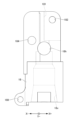
- FIG. 13 is a side view of the fixing member as viewed in the X+ direction.
- 11 is a cross-sectional view of the magazine as viewed in the Y+ direction.
- FIG. 8 is a cross-sectional view of the pot body as viewed in the X-direction, specifically, a cross-section taken along line fig. 8-fig. 8 in FIG. 7.
- FIG. 1 is a cross-sectional view of a pot body with a clamp mechanism attached thereto, as viewed in the X-direction.
- 11 is a cross-sectional view taken in the X-direction, showing a state in which a position maintaining member is further attached to the pot body.
- FIG. 1 is a cross-sectional view of a tool pot holding a tool as viewed in the X-direction.
- FIG. 13 is a view of the pot body viewed in the Y+ direction.
- 4 is a cross-sectional view of the arm rotating device as viewed in the Y+ direction.
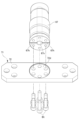
- FIG. FIG. 4 is an exploded perspective view showing a pivot member and an arm base.
- FIG. 11 is a cross-sectional view of the lower part of the pivot member and the arm base as viewed in the Y+ direction.
- FIG. FIG. 13 is a view of the arm as viewed in the Y+ direction.
- FIG. 13 is a view showing the arm and the spindle-side cam Cs as viewed in the Y+ direction.
- 1 is a perspective view showing a first gripping member 77 and its surroundings.
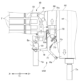
- FIG. 13 is a view of the first gripping member 77 and its surroundings as viewed in the Y+ direction.
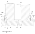
- 22 is a cross-sectional view of the first gripping member 77 and the first base member as viewed in the Y+ direction, specifically, a cross-section taken along line fig22-fig22 in FIG. 18.
- FIG. 13 is a cross-sectional view of a first gripping member 77 and a first base member in a comparative example, viewed in the Y+ direction.
- FIG. 4 is a diagram showing an initial state of tool replacement by the tool replacement device.
- FIG. FIG. FIG. FIG. FIG. FIG. FIG. FIG. FIG. FIG. 11 is a perspective view showing a tool pot according to a second embodiment.
- 35 is a cross-sectional view of the tool pot as viewed in the X-direction, specifically, a cross-section taken along line fig. 35-fig. 35 shown in FIG. 34.
- 11 is a cross-sectional view taken in the X-direction, showing a state in which a tool is being held in the tool pot.
- FIG. 1 is a cross-sectional view of a tool pot holding a tool as viewed in the X-direction.
- FIG. 38 is a cross-sectional view of the tool pot seen from below, specifically, a cross-section taken along line fig 38-fig 38 shown in FIG. 37.
- FIG. 11 is a perspective view showing another example of a bridge.
- Tool changer 80 shown in Fig. 1 is installed relative to machine tool 90 as shown in Fig. 2.
- X direction two predetermined directions that are perpendicular to each other in a horizontal plane as shown in Fig. 1
- Y direction two predetermined directions that are perpendicular to each other in a horizontal plane as shown in Fig. 1
- X- direction two predetermined directions that are perpendicular to each other in a horizontal plane as shown in Fig. 1
- the opposite direction will be referred to as the "X+ direction”.
- Y- direction the opposite direction
- Y+ direction the opposite direction
- the machine tool 90 includes a spindle assembly 95.
- the spindle assembly 95 has a spindle 97 and a housing 96.
- the spindle 97 is installed with its axial length oriented in the vertical direction.
- the housing 96 covers the spindle 97.
- the spindle assembly 95 is configured to be capable of being raised and lowered.
- the base end of one of the multiple tools T is attached to the lower end of the spindle 97.
- a pull stud bolt pB is provided at the base end of each tool T.
- the tool T of the multiple tools T that has been attached to the spindle 97 so far will be referred to as the "previously used tool Tp”
- the tool T of the multiple tools T that will be next attached to the spindle 97 will be referred to as the "next used tool Tn.”
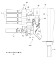
- the tool changer 80 includes a control device 51, and also includes a magazine 30, a magazine rotation device 39, an arm 70, an arm rotation device 60, an arm lifting device 55, and a pot drive mechanism 40 within the internal space wS of the machine tool 90.
- the "magazine 30" may be read as the "tool magazine”
- the arm 70 may be read as the "tool changer arm”.
- the magazine 30 and the spindle assembly 95 are arranged side by side in the X direction, and specifically, the spindle assembly 95 is arranged on the +X direction side of the magazine 30.
- the arm rotation device 60 is provided between the magazine 30 and the spindle assembly 95.
- the pot drive mechanism 40 is provided between the magazine 30 and the arm rotation device 60.
- the arm 70 is provided below the arm rotation device 60.
- the arm lifting device 55 is provided above the arm rotation device 60.
- the magazine 30 shown in FIG. 1 includes a magazine base 38, a rotating member 35, and a plurality of tool pots 10.
- the rotating member 35 is attached to the magazine base 38 so as to be rotatable about an axis in the X direction.
- the magazine rotation device 39 is attached to the magazine base 38.
- the magazine rotation device 39 includes an actuator such as a motor.
- the magazine rotation device 39 rotates the rotating member 35 about an axis in the X direction relative to the magazine base 38.
- the multiple tool pots 10 are attached to the rotating member 35 in a line in the direction of rotation. As a result, by rotating the rotating member 35, one of the multiple tool pots 10 is placed in the lowest "exchange position ep" which serves as a standby position for tool exchange.
- the tool pot 10 at the exchange position ep rotates around the axis in the Y direction to an exchange angle Ea shown in FIG. 26 and a storage angle Sa shown in FIG. 24.
- the exchange angle Ea shown in FIG. 26 is the angle at which the held tool T can be exchanged, and more specifically, the angle at which the tool pot 10 stands upright in the vertical direction.
- the storage angle Sa shown in FIG. 24 is the angle at which the held tool T is stored, and more specifically, the angle at which the tool pot 10 lies down in the X direction.
- the magazine 30 further includes a plurality of biasing members 31 and a fixed member 34.
- Each biasing member 31 is provided for each tool pot 10.
- the fixed member 34 is a metal member fixed to the swivel member 35.
- the fixed member 34 extends in an annular shape in the swivel direction of the swivel member 35.
- the fixed member 34 has support portions 344 arranged in the swivel direction of the swivel member 35.
- the support portions 344 are provided for each tool pot 10.
- each support portion 344 is key-shaped so as to be able to engage with the end of the biasing member 31.
- each biasing member 31 biases the corresponding tool pot 10 toward the storage angle Sa.
- each tool pot 10 includes a pot body 18, a clamping mechanism 12, and a posture maintaining member 13.
- Each pot body 18 is made of resin. As shown in FIG. 1, each pot body 18 is attached to the rotating member 35 so as to be rotatable about an axis Ax that extends in a tangential direction to the rotating direction of the rotating member 35. Therefore, the tool pot 10 at the exchange position ep shown in FIG. 3 can rotate about an axis in the Y direction.
- the upper part of the pot body 18 is provided with a recess 181 for mounting the pot roller 48 described later. Furthermore, as shown in FIG. 12, the pot body 18 is provided with a roller hole 182, an axle hole 184, and an engagement hole 188.
- the roller hole 182 is a hole for mounting a shaft material that rotatably supports the pot roller 48 described later.
- the axle hole 184 is a hole for mounting the aforementioned shaft material Ax. As described above, one end of the urging member 31 is inserted into the engagement hole 188.
- the tool pot 10 is configured as follows when viewed at the exchange angle Ea in the exchange position ep shown in Figure 2.
- the pot body 18 has an insertion hole 18v extending upward from the bottom end of the pot body 18, into which the pull stud bolt pB of the tool T can be inserted. Therefore, the pot body 18 is cylindrical and opens downward. As shown in FIG. 8, the upper part of the pot body 18 has a clamp attachment hole 18h extending in the Y direction and intersecting with the insertion hole 18v.
- the clamp mechanism 12 includes a clamp base 122, a pair of contact members 127, and a pair of biasing members 126.
- the clamp base 122 is a metal member.
- Each biasing member 126 is a metal compression spring.
- Each contact member 127 is a metal ball.
- the clamp mechanism 12 is made of metal.
- the clamp base 122 extends in the Y direction, and a cylindrical hole 122h extending in the Y direction is provided on the inside of the clamp base 122.
- the clamp base 122 is cylindrical.
- a clamp hole 122v is provided in the center of the clamp base 122 in the Y direction, which passes through the clamp base 122 in the vertical direction and intersects with the cylindrical hole 122h.
- a head 122e is formed on the end of the clamp base 122 on the Y+ direction side, protruding radially outward from the clamp base 122 further than other parts.
- the clamp base 122 is attached to the pot body 18 by inserting the clamp base 122 into the clamp mounting hole 18h in the Y+ direction.
- a pair of contact members 127 are installed inside the cylindrical hole 122h. Specifically, the Y- side contact member 127 is installed on the Y- side of the axis of the clamp hole 122v so that it can be displaced in the Y direction. On the other hand, the Y+ side contact member 127 is installed on the Y+ side of the axis of the clamp hole 122v so that it can be displaced in the Y direction.
- the pair of biasing members 126 are installed in the cylindrical hole 122h at a position located outside the pair of contact members 127 in the Y direction.
- Retainers 125 are attached to both ends of the clamp base 122 in the Y direction to hold the outer ends of the pair of biasing members 126 in the Y direction.
- each biasing member 126 is interposed between the retainer 125 and the contact member 127, and biases the contact member 127 inward in the Y direction.
- the biasing member 126 on the Y- side biases the contact member 127 on the Y- side in the Y+ direction
- the biasing member 126 on the Y+ side biases the contact member 127 on the Y+ side in the Y- direction.
- the clamp base 122 has an engagement recess 122d that is recessed upward in the area including the lower end of the clamp hole 122v and its surrounding area.
- the posture-maintaining member 13 shown in FIG. 7 is a metal member that is inserted into the insertion hole 18v of the pot body 18.
- An insertion hole 13v is formed in the posture-maintaining member 13.
- a protrusion 131 that protrudes upward is formed in the inner peripheral portion of the posture-maintaining member 13, i.e., the portion on the insertion hole 13v side.
- the projection 131 of the attitude-maintaining member 13 is engaged with the engagement recess 122d of the clamp base 122 by press-fitting or the like.
- the insertion hole 13v of the attitude-maintaining member 13 is a hole for passing the pull stud bolt pB to the clamp mechanism 12 when the pull stud bolt pB is inserted into the insertion hole 18v of the pot body 18.
- the insertion hole 13v has a tapered shape that reduces in diameter as it advances upward, i.e., toward the clamp mechanism 12. This allows the insertion hole 13v to guide the pull stud bolt pB into the clamp hole 122v of the clamp mechanism 12.
- the pair of contact members 127 When the pull stud bolt pB is inserted into the clamp hole 122v shown in FIG. 10, the pair of contact members 127 are pushed outward in the Y direction by the pull stud bolt pB, and then, as shown in FIG. 11, the pair of contact members 127 return to the inside in the Y direction. As a result, the pair of contact members 127 hold the pull stud bolt pB from the outside in the Y direction.
- the arm lifting device 55 includes an actuator such as a motor.
- the arm lifting device 55 raises and lowers the arm rotation device 60 to which the arm 70 is attached, thereby raising and lowering the arm rotation device 60 and the arm 70.
- the uppermost point in the driving range of the arm 70 by the arm lifting device 55 will be referred to as the "uppermost point of the arm,” and the lowermost point in that driving range will be referred to as the "lowest point of the arm.”
- the pot drive mechanism 40 shown in Figure 2 includes a pot drive cam 41, a link roller 45, a link mechanism 46, and a pot roller 48.
- the pot drive cam 41 is attached to the arm rotation device 60 and moves up and down together with the arm rotation device 60 and the arm 70.
- the link roller 45 is attached to the upper end of the link mechanism 46.
- the pot roller 48 is attached to the lower part of the end of the pot body 18 on the X+ direction side so as to be rotatable about an axis in the Y direction.
- the link roller 45 is biased against the pot drive cam 41 by the weight of the link mechanism 46 and the biasing force of the biasing member 31.
- the arm rotation device 60 shown in FIG. 2 includes a driving source 62, a housing 64, a reducer 65, a seal member 66, and a pivot member 67.
- the driving source 62 is an actuator such as a motor.
- the housing 64 has a cylindrical shape that opens at the top and bottom. An internal space iS is formed inside the housing 64.
- the reducer 65 is stored in the internal space iS.
- the upper opening of the housing 64 is closed by the driving source 62.
- the pivot member 67 is provided below the reducer 65.
- the driving source 62 rotates the pivot member 67 via the reducer 65.
- the seal member 66 closes the lower opening of the housing 64 while allowing the pivot member 67 to pass in the vertical direction.
- a base plate 72, which is part of an arm base 71, which is part of an arm 70, is fixed to the lower end of the pivot member 67. As a result, the arm 70 rotates around the vertical axis together with the pivot member 67.
- a through hole 67v is provided in the pivot shaft member 67, and a communication passage Ph is formed between the pivot shaft member 67 and the base plate 72.
- the through hole 67v and the communication passage Ph allow the internal space iS to communicate with the outside of the housing 64.
- the through hole 67v penetrates the pivot shaft member 67 in the vertical direction. Therefore, the upper end of the through hole 67v is connected to the internal space iS.
- a communication groove 67h is provided on the lower surface of the pivot shaft member 67, extending from the lower end of the through hole 67v to the outer circumferential surface of the pivot shaft member 67. Note that in this embodiment, there are two communication grooves 67h, but there may be one, or three or more.
- the upper surface of the base plate 72 is provided with an engagement recess 72d.
- the lower end of the pivot shaft member 67 engages with the engagement recess 72d.
- the base plate 72 is fixed to the lower end of the pivot shaft member 67 by a bolt Bt or the like.
- a communication passage Ph is formed inside the inner wall of the communication groove 67h.
- the vertical depth of the engagement recess 72d is deeper than the vertical depth of the communication groove 67h.
- an upward extension portion 67e is formed, which extends upward from the ceiling surface of the end of the communication groove 67h on the outer periphery side of the pivot shaft member 67 and opens to the outside.
- the inside of the inner wall of this upward extension portion 67e is also part of the communication passage Ph.
- the communication passage Ph includes the inside of the inner wall of the communication groove 67h and the inside of the inner wall of the upward extension portion 67e.
- the ceiling surface of the communication groove 67h i.e., the ceiling surface of the communication passage Ph other than the upward extension portion 67e, is located lower than the lower end Lp of the opening of the communication passage Ph on the outer peripheral surface side of the rotating shaft member 67, i.e., the upper surface of the base plate 72.
- the gas in the through hole 67v is sucked in, but by ensuring that the length of the through hole 67v is sufficient, the cutting fluid cf that has accumulated in the communication passage Ph can only rise to the middle of the through hole 67v.
- the arm 70 shown in FIG. 2 comprises an arm base 71, a first gripping member 77, a second gripping member 78, a first biasing member 75, and a second biasing member 76.
- the arm base 71 includes a first base member 73 and a second base member 74.
- the state in which the arm 70 is at a predetermined rotation angle is referred to as the "first basic state bS1," and as shown in FIG. 29, the state in which the arm 70 is rotated 180° around the vertical axis from the first basic state bS1 is referred to as the "second basic state bS2.”
- the arm 70 is configured as follows.
- the first base member 73 is attached to the underside of the portion of the base plate 72 on the Y+ direction side.
- the second base member 74 is attached to the underside of the portion of the base plate 72 on the Y- direction side.
- the first gripping member 77 has a broken line shape that extends downward and then in the X- direction.
- the second gripping member 78 has a broken line shape that extends downward and then in the X+ direction.
- the upper end of the first gripping member 77 is attached to the first base member 73 by a first shaft member Ax1 extending in the Y direction so as to be rotatable about an axis in the Y direction.
- the upper end of the second gripping member 78 is attached to the second base member 74 by a second shaft member Ax2 extending in the Y direction so as to be rotatable about an axis in the Y direction. In this way, the first gripping member 77 and the second gripping member 78 are attached to the arm base 71.
- a first gripping portion 77e is provided at the tip of the first gripping member 77.
- a second gripping portion 78e is provided at the tip of the second gripping member 78.
- the first gripping member 77 and the second gripping member 78 will be collectively referred to as “gripping members 77, 78.”
- the first gripping portion 77e and the second gripping portion 78e will be collectively referred to as “gripping portions 77e, 78e.”
- Each gripping portion 77e, 78e has a U-shape that opens toward the tip, and is configured to be able to grip the portion of the upper part of the tool T below the pull stud bolt pB.
- each of the gripping members 77, 78 is displaced between a gripping angle Ga for gripping the tool T and a release angle Ra for releasing the grip of the tool T by rotating about an axis in the Y direction.
- the first biasing member 75 and the second biasing member 76 are both tension springs.
- the first biasing member 75 has one end attached to the first gripping member 77 and the other end attached to the first base member 73.
- the second biasing member 76 has one end attached to the second gripping member 78 and the other end attached to the second base member 74.
- the first biasing member 75 biases the first gripping member 77 toward the gripping angle Ga.
- the second biasing member 76 biases the second gripping member 78 toward the gripping angle Ga.
- a first roller 77r is attached to the first gripping member 77.
- a second roller 78r is attached to the second gripping member 78.
- a magazine side cam Cm is provided on the X- direction side of the arm 70.
- the magazine side cam Cm is attached to the frame or housing of the tool changer 80.
- a spindle side cam Cs is provided on the X+ direction side of the arm 70.
- the spindle side cam Cs is attached to the frame or housing 96 of the spindle assembly 95, and rises and falls together with the spindle assembly 95. Note that the "spindle side cam Cs" may be read as a "pressure member".
- the underside of the end of the first base member 73 on the X-direction side forms a first abutment surface 73s.
- the first abutment surface 73s abuts against the first gripping member 77 at a position that prevents rotation toward the gripping angle Ga, thereby limiting the range of rotation of the first gripping member 77 toward the gripping angle Ga.
- a first abutment surface 77s that abuts parallel to the first abutment surface 73s from below is provided on the upper part of the first gripping member 77.
- the underside of the end portion on the X+ direction side of the second base member 74 constitutes a second abutment surface 74s.
- the second abutment surface 74s abuts against the second gripping member 78 at a position that prevents rotation toward the gripping angle Ga, thereby limiting the range of rotation of the second gripping member 78 toward the gripping angle Ga.
- a second abutment surface 78s that abuts parallel to the second abutment surface 74s from below is provided on the upper portion of the second gripping member 78.
- the above explanation is for the arm 70 when viewed in the first basic state bS1.
- the explanation for the arm 70 when viewed in the second basic state bS2 is similar to the above explanation, except that "first" and "second" are read as the other, and the reference numerals are read as appropriate.
- the first gripping member 77 shown in FIG. 22 repeatedly collides with the first abutment surface 73s by repeatedly rotating toward the gripping angle Ga side and toward the release angle Ra side. If the first gripping member 77 slides against the first abutment surface 73s during this collision, wear will progress on the first abutment surface 73s and the first gripping member 77, which may cause malfunction of the arm 70. Similarly, if the second gripping member 78 slides against the second abutment surface 74s, wear will progress on the second abutment surface 74s and the second gripping member 78, which may cause malfunction of the arm 70.
- the first abutment surface 73s extends along a first imaginary plane Vp1 that includes the entire rotation axis 77c of the first gripping member 77, i.e., the entire center line of the first shaft material Ax1.
- the tangent direction of the rotation direction of the first gripping member 77 on the first abutment surface 73s necessarily faces the direction perpendicular to the surface of the first abutment surface 73s. This suppresses the generation of a force that would cause the first gripping member 77 to shift parallel to the first abutment surface 73s.
- the tangent direction of the rotation direction of the first gripping member 77 at the first abutment surface 73s is inclined with respect to the perpendicular direction of the first abutment surface 73s. This makes it easier for a force to be applied that causes the first gripping member 77 to shift parallel to the first abutment surface 73s.
- this embodiment makes it possible to reduce sliding when the first gripping member 77 collides with the first abutment surface 73s.
- the second abutment surface 74s extends along the second imaginary plane Vp2 that includes the entire rotation axis 78c of the second gripping member 78, i.e., the entire center line of the second shaft material Ax2. Therefore, for the same reason as in the case of the first abutment surface 73s, sliding can be suppressed when the second gripping member 78 collides with the second abutment surface 74s.
- the second problem to be solved by the arm 70 of this embodiment will be described.
- the power to the arm rotation device 60 is usually also turned off.
- the arm 70 is released from the current rotation phase that was held by the arm rotation device 60.
- the spindle side cam Cs is pressing against the second gripping member 78 or when the spindle side cam Cs is pressing against the first gripping member 77, if the power to the arm rotation device 60 is turned off, the arm 70 will rotate due to the pressing force.
- the arm 70 is configured as follows.
- a plate-shaped first rotation stop member 73z that protrudes from the first base member 73 in the Y+ direction is provided on the X- direction side of the upper surface of the first base member 73.
- a plate-shaped second rotation stop member 74z that protrudes from the second base member 74 in the Y- direction is provided on the X+ direction side of the upper surface of the second base member 74.
- the first rotation stop member 73z and the second rotation stop member 74z are collectively referred to as "rotation stop members 73z, 74z.”
- the second rotation stop member 74z is disposed to the side of the spindle side cam Cs in the Y+ direction with a small clearance CLh as shown in FIG. 18. This second rotation stop member 74z restricts the rotation of the arm 70 when the power supply to the arm rotation device 60 is turned OFF.
- the above explanation is for the arm 70 when viewed in the first basic state bS1.
- the explanation for the arm 70 when viewed in the second basic state bS2 is similar to the above explanation, except that "first" and "second" are read as the other, and the reference numerals are read as appropriate.
- control device 51 controls each drive device, including the magazine rotation device 39, the arm rotation device 60, and the arm lifting device 55.
- the specific procedure for tool replacement based on the control by the control device 51 will be described below.
- the arm 70 in the initial state, the arm 70 is at the uppermost point. At this time, the arm 70 may be in either the first basic state bS1 or the second basic state bS2. Below, a case where the arm 70 is in the first basic state bS1 in the initial state will be described.
- the tool pot 10 at the replacement position ep is positioned at a storage angle Sa according to the profile of the pot drive cam 41.
- the first gripping member 77 is positioned at a release angle Ra according to the profile of the magazine-side cam Cm, and the second gripping member 78 is also positioned at a release angle Ra according to the profile of the spindle-side cam Cs.
- the first gripping member 77 rotates to a gripping angle Ga according to the profile of the magazine side cam Cm, and grips the next tool to be used Tn in the tool pot 10 at an exchange angle Ea. From that state, as shown in FIG. 27, the first gripping member 77 descends to remove the next tool to be used Tn from the tool pot 10.
- the second gripping member 78 rotates toward the gripping angle Ga in accordance with the profile of the spindle-side cam Cs to grip the previously used tool Tp on the spindle 97. From this state, as shown in FIG. 28, the second gripping member 78 descends relative to the spindle 97 to remove the previously used tool Tp from the spindle 97.
- the arm 70 is rotated 180° around the vertical axis by the arm rotation device 60.
- This rotation changes the state from the first basic state bS1 to the second basic state bS2.
- the second gripping member 78 and the previously used tool Tp are on the X- side
- the first gripping member 77 and the next tool to be used Tn are on the X+ side.
- the tool pot 10 at the exchange position ep rotates to the exchange angle Ea according to the profile of the pot drive cam 41 as shown in FIG. 31, and then rotates again to the storage angle Sa as shown in FIG. 32 and FIG. 33.
- the second gripping member 78 rises as shown in FIG. 31 to attach the previously used tool Tp to the tool pot 10 at the exchange angle Ea. From that state, as shown in FIG. 32, the second gripping member 78 rotates toward the release angle Ra in accordance with the profile of the magazine-side cam Cm, and releases its grip on the previously used tool Tp.
- the above describes the case where the initial state is the first basic state bS1.
- the explanation for the case where the initial state is the second basic state bS2 is similar to the above explanation, except that "first" and "second” are read as the other, and the symbols are read as the corresponding ones.
- the fixed member 34 is fixed to the swivel member 35 and extends in the swivel direction.
- the fixed member 34 has support parts 344 arranged in the swivel direction for each tool pot 10.
- a biasing member 31 is provided for each tool pot 10.
- Each biasing member 31 is attached to the corresponding tool pot 10 and the corresponding support part 344, and biases the corresponding tool pot toward the storage angle Sa. Therefore, a single fixed member 34 can support multiple biasing members 31 on the swivel member 35. Therefore, multiple biasing members 31 can be supported on the swivel member 35 without providing a support member for supporting the biasing member 31 on the magazine base 38 for each tool pot 10. This reduces the assembly man-hours for the tool magazine 30 and the manufacturing cost.
- the biasing member 31 is a tension spring.
- Each support portion 344 has a key shape that can engage with the end of the biasing member 31. This allows the fixing member 34 to be realized with a simple shape.
- the fixing member 34 is annular and goes around in the rotation direction of the rotating member 35. Therefore, the strength of the fixing member 34 can be ensured more efficiently than when the fixing member 34 is C-shaped, for example.
- the fixing member 34 is made of metal. This also ensures the strength of the fixing member 34 efficiently.
- the clamp mechanism 12 is attached to the clamp attachment hole 18h.
- the posture-maintaining member 13 is inserted into the insertion hole 18v and maintains the posture of the clamp mechanism 12 relative to the pot body 18. Therefore, the posture of the clamp mechanism 12 relative to the pot body 18 can be maintained without using screws or the like. This makes it possible to select a material for the pot body 18 that is difficult to secure with screws in terms of strength, and to simplify the structure of the pot body 18. This leads to a reduction in weight, size, and cost of the tool pot 10.
- the posture-maintaining member 13 is formed with an insertion hole 13v that allows the pull stud bolt pB to pass through to the clamp mechanism 12 when the pull stud bolt pB is inserted into the insertion hole 18v. Therefore, the posture-maintaining member 13 does not impede the passage of the pull stud bolt pB, and the outer shape of the posture-maintaining member 13 is necessarily larger than the outer shape of the pull stud bolt pB. This allows the size of the posture-maintaining member 13 to be sufficiently large within a limited space such as the inside of the pot body 18. This allows the posture of the clamp mechanism 12 relative to the pot body 18 to be sufficiently firmly maintained.
- the tool pot 10 can be made lighter, smaller, and less expensive, while still maintaining a sufficiently strong position of the clamp mechanism 12 relative to the pot body 18.
- a protrusion 131 that protrudes toward the clamp mechanism 12 is formed on the portion of the posture maintaining member 13 on the side of the insertion hole 13v. As shown in Figure 10, the protrusion 131 engages with the clamp mechanism 12, thereby maintaining the posture of the clamp mechanism 12 relative to the pot body 18. This allows the posture of the clamp mechanism 12 to be maintained with a simple shape.
- the insertion hole 13v has a tapered shape that narrows toward the clamp mechanism 12. Therefore, the insertion hole 13v can guide the pull stud bolt pB into the clamp mechanism 12.
- the pot body 18 shown in FIG. 10 is made of resin. This allows the tool pot 10 to be made lighter, smaller, and less expensive.
- the clamp mechanism 12 and the posture-maintaining member 13 are made of metal. This ensures that the clamp mechanism 12, which actually holds the tool, and the posture-maintaining member 13, which maintains its posture, have sufficient strength.
- the posture-maintaining member 13 maintains the posture of the clamp mechanism 12 relative to the pot body 18 by engaging with the clamp base 122, which houses a pair of contact members 127 and a pair of biasing members 126 inside. This allows the posture of the clamp mechanism 12 to be maintained in a simple manner.
- the pivot shaft member 67 is provided with a through hole 67v that extends vertically and whose upper end communicates with the internal space iS.
- a base plate 72 is attached to the lower end of the pivot shaft member 67.
- a communication passage Ph is formed between the pivot shaft member 67 and the base plate 72, connecting the lower end of the through hole 67v to the outside of the outer circumferential surface of the pivot shaft member 67. Therefore, even if cutting fluid enters and accumulates in the internal space iS, the cutting fluid can be discharged through the through hole 67v and the communication passage Ph to the in-machine space wS.
- the ceiling surface of the communication groove 67h i.e., the ceiling surface of the communication passage Ph other than the upward extension portion 67e, is located at a lower position than the lower end Lp of the opening of the communication passage Ph on the outer peripheral surface side of the rotating shaft member 67.
- the first abutment surface 73s extends along the first imaginary plane Vp1 that includes the entire rotation axis 77c of the first gripping member 77, i.e., the entire center line of the first shaft material Ax1.
- the tangent direction of the rotation direction of the first gripping member 77 on the first abutment surface 73s necessarily faces the direction perpendicular to the surface of the first abutment surface 73s.
- the first gripping member 77 has a first contact surface 77s that contacts the first abutment surface 73s in parallel. Therefore, compared to when, for example, a roller or the like of the first gripping member 77 makes linear contact with the first abutment surface 73s, the contact area of the first gripping member 77 with the first abutment surface 73s can be increased, thereby reducing wear between the first abutment surface 73s and the first gripping member 77.
- the second gripping member 78 has a second contact surface 78s that contacts the second abutment surface 74s in parallel. Therefore, for the same reason as above, wear between the second abutment surface 74s and the second gripping member 78 can be reduced.
- the arm 70 is provided with a first rotation stop member 73z and a second rotation stop member 74z.
- the second rotation stop member 74z stops the rotation by abutting against the spindle side cam Cs at a position that prevents the rotation due to the pressure.
- the first rotation stop member 73z stops the rotation by abutting against the spindle side cam Cs at a position that prevents the rotation due to the pressure.
- the first rotation stop member 73z or the second rotation stop member 74z can prevent the arm 70 from rotating due to the pressure.
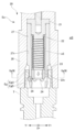
- This embodiment differs from the first embodiment in that the magazine 30 shown in FIG. 4 includes a plurality of tool pots 20 shown in FIG. 34 instead of a plurality of tool pots 10. Note that the pot rollers are not shown in FIG. 34. Also, as shown in FIG. 36, this embodiment differs in that an engagement portion Eg is formed at the base end of each tool T instead of a pull stud bolt pB.
- the engagement portion Eg has an upper portion EgU and a lower portion EgD. The upper portion EgU protrudes more toward the inner circumference of the tool T than the lower portion EgD. Note that the engagement portion Eg may be read as the "end of the tool.”
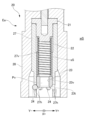
- the tool pot 20 includes a pot body 28, a cylindrical member 27, a biasing member 22, a piece 23, and a number of contact members 24.
- the pot body 28 is made of resin.
- the cylindrical member 27 is made of metal.
- the biasing member 22 is a metal compression spring.
- the piece 23 is made of metal.
- Each contact member 24 is a metal ball.
- the tool pot 20 is configured as follows when viewed in the state shown in FIG. 35, i.e., when the tool pot 20 is positioned at the exchange angle Ea in the exchange position ep.
- the pot body 28 has a cylindrical shape that opens downward, and is configured so that the engagement portion Eg of the tool T can be inserted from below, as shown in Figures 36 and 37. Therefore, “upward” in the following may be read as “the direction in which the tool T is inserted,” and “downward” in the following may be read as "the direction opposite to the insertion of the tool T.”
- the cylindrical member 27 is fixed inside the pot body 28 with its axis oriented vertically.
- the piece 23 is installed inside the lower end of the cylindrical member 27 so that it can be displaced vertically.
- the space inside the cylindrical member 27 above the piece 23 is referred to as the "storage space sS.”
- the biasing member 22 is stored in the storage space sS.
- a retainer 21 for holding the upper end of the biasing member 22 is attached to the upper end of the cylindrical member 27.
- the biasing member 22 is interposed between the retainer 21 and the piece 23, and biases the piece 23 downward.
- a number of mounting holes 27h are provided through the lower end of the cylindrical member 27. In the bottom view shown in FIG. 38, these mounting holes 27h extend radially in the radial direction of the cylindrical member 27.
- Each contact member 24 is attached to one of the mounting holes 27h. As a result, each contact member 24 is configured to be able to protrude outward from the outer periphery of the cylindrical member 27 and retract inward. Note that although the figure shows three contact members 24, the number may be two or less, or four or more.
- the piece 23 has a tapered surface 23t at its lower end.
- the tapered surface 23t presses the multiple contact members 24, causing them to protrude outward from the outer periphery of the lower end of the tubular member 27.
- a communication passage Pv is formed in the bridge 23.
- the communication passage Pv is configured as follows:
- the communication passage Pv extends from the upper end to the lower end of the piece 23, connecting the storage space sS with the outside.
- a communication hole 23v is formed as the communication passage Pv, as shown in FIG. 39.
- the communication hole 23v penetrates the piece 23 in the vertical direction.
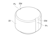
- a communication groove 23d may be formed as the communication passage Pv, as shown in FIG. 40.
- the communication groove 23d is recessed into the outer circumferential surface of the piece 23 and extends in the vertical direction. Note that the above explanation is for the case where the tool pot 20 is arranged at the exchange angle Ea in the exchange position ep, as described above.
- the coolant if coolant or the like infiltrates from the internal space wS shown in FIG. 35 into the storage space sS, the coolant is discharged from the communication passage Pv.
- the embodiment described above can be modified, for example, as follows.
- the arm 70 shown in Fig. 16 may have three or more gripping members 77, 78 instead of two.
- the arm rotation device 60 shown in Fig. 2 may rotate the arm 70 by 120° instead of 180°.
- the tool magazine (30) described in appendix 1 to 4 below can be realized.
- a rotating member (35) configured to be capable of rotating in a predetermined rotation direction; tool pots (10, 20) attached to the rotating member (35) in a line in the rotating direction, each of which is configured to be able to hold a tool (T) of a machine tool (90); by the rotation of the pivoting member (35), one of the plurality of tool pots (10, 20) is disposed at a predetermined exchange position (ep); Each of the tool pots (10, 20) is configured to be displaceable between an exchange angle (Ea) at which the tool (T) held therein can be exchanged and a storage angle (Sa) at which the held tool (T) is stored, at the exchange position (eP).
- Ea exchange angle
- Sa storage angle
- a tool magazine (30) comprising:
- the biasing member (31) is a tension spring, Each of the support portions (344) has a key shape that can be engaged with an end of the biasing member (31). 2.
- the fixing member (34) is annular and rotates in the rotation direction. 3.
- the fixing member (34) is made of metal. 4.
- the tool magazine (30) according to any one of claims 1 to 3.
- Tool pot 20 Tool pot 34 Fixed member 344 Support portion 35 Swivel member 90 Machine tool T Tool ep Exchange position Ea Exchange angle Sa Storage angle
Landscapes
- Engineering & Computer Science (AREA)
- Mechanical Engineering (AREA)
- Automatic Tool Replacement In Machine Tools (AREA)
Priority Applications (6)
| Application Number | Priority Date | Filing Date | Title |
|---|---|---|---|
| CN202380098867.2A CN121263272A (zh) | 2023-06-08 | 2023-06-08 | 工具匣 |
| DE112023006067.3T DE112023006067T5 (de) | 2023-06-08 | 2023-06-08 | Werkzeugmagazin |
| PCT/JP2023/021435 WO2024252645A1 (ja) | 2023-06-08 | 2023-06-08 | 工具マガジン |
| KR1020257038921A KR20250171423A (ko) | 2023-06-08 | 2023-06-08 | 공구 매거진 |
| JP2025525890A JPWO2024252645A1 (https=) | 2023-06-08 | 2023-06-08 | |
| TW113118708A TW202448623A (zh) | 2023-06-08 | 2024-05-21 | 工具匣 |
Applications Claiming Priority (1)
| Application Number | Priority Date | Filing Date | Title |
|---|---|---|---|
| PCT/JP2023/021435 WO2024252645A1 (ja) | 2023-06-08 | 2023-06-08 | 工具マガジン |
Publications (1)
| Publication Number | Publication Date |
|---|---|
| WO2024252645A1 true WO2024252645A1 (ja) | 2024-12-12 |
Family
ID=93795565
Family Applications (1)
| Application Number | Title | Priority Date | Filing Date |
|---|---|---|---|
| PCT/JP2023/021435 Ceased WO2024252645A1 (ja) | 2023-06-08 | 2023-06-08 | 工具マガジン |
Country Status (6)
| Country | Link |
|---|---|
| JP (1) | JPWO2024252645A1 (https=) |
| KR (1) | KR20250171423A (https=) |
| CN (1) | CN121263272A (https=) |
| DE (1) | DE112023006067T5 (https=) |
| TW (1) | TW202448623A (https=) |
| WO (1) | WO2024252645A1 (https=) |
Citations (2)
| Publication number | Priority date | Publication date | Assignee | Title |
|---|---|---|---|---|
| JP2001225238A (ja) * | 2000-02-10 | 2001-08-21 | Brother Ind Ltd | 工具収納装置 |
| CN110900275A (zh) * | 2018-09-18 | 2020-03-24 | 林彦辰 | 圆盘式刀库改良结构 |
Family Cites Families (1)
| Publication number | Priority date | Publication date | Assignee | Title |
|---|---|---|---|---|
| TWI716887B (zh) | 2019-05-28 | 2021-01-21 | 陳君杰 | 換刀單元及具有該換刀單元之換刀裝置 |
-
2023
- 2023-06-08 DE DE112023006067.3T patent/DE112023006067T5/de active Pending
- 2023-06-08 WO PCT/JP2023/021435 patent/WO2024252645A1/ja not_active Ceased
- 2023-06-08 CN CN202380098867.2A patent/CN121263272A/zh active Pending
- 2023-06-08 KR KR1020257038921A patent/KR20250171423A/ko active Pending
- 2023-06-08 JP JP2025525890A patent/JPWO2024252645A1/ja active Pending
-
2024
- 2024-05-21 TW TW113118708A patent/TW202448623A/zh unknown
Patent Citations (2)
| Publication number | Priority date | Publication date | Assignee | Title |
|---|---|---|---|---|
| JP2001225238A (ja) * | 2000-02-10 | 2001-08-21 | Brother Ind Ltd | 工具収納装置 |
| CN110900275A (zh) * | 2018-09-18 | 2020-03-24 | 林彦辰 | 圆盘式刀库改良结构 |
Also Published As
| Publication number | Publication date |
|---|---|
| TW202448623A (zh) | 2024-12-16 |
| KR20250171423A (ko) | 2025-12-08 |
| JPWO2024252645A1 (https=) | 2024-12-12 |
| CN121263272A (zh) | 2026-01-02 |
| DE112023006067T5 (de) | 2026-02-12 |
Similar Documents
| Publication | Publication Date | Title |
|---|---|---|
| JPWO2009122495A1 (ja) | ピン位置決め冶具及びピン装着装置 | |
| JP2008182830A (ja) | ブラシレスモータ、ディスク駆動装置 | |
| WO2024252645A1 (ja) | 工具マガジン | |
| WO2024252644A1 (ja) | 工具交換アーム | |
| WO2024252633A1 (ja) | 工具ポット | |
| WO2024252642A1 (ja) | 工具交換装置 | |
| WO2024252646A1 (ja) | 工具交換装置 | |
| WO2024252635A1 (ja) | 工具ポット | |
| ITMI20070638A1 (it) | Dispositivo di serraggio di una tavola | |
| JP4439241B2 (ja) | 旋盤の主軸ブレーキ装置 | |
| WO2019155509A1 (ja) | 電磁ブレーキ装置、巻上機及びエレベーター | |
| CN110890816B (zh) | 转子轴入轴工装 | |
| JP2019055467A (ja) | スプリング装着装置 | |
| CN218927014U (zh) | 一种刹车盘铣削用具有调平功能的加工装置 | |
| CN217182006U (zh) | 一种绕线治具中的转盘定位机构 | |
| JP7518751B2 (ja) | 調芯機構および同機構を備えた自動締結機 | |
| CN110561313B (zh) | 一种凸轮片夹具 | |
| JPH0141690Y2 (https=) | ||
| KR102146874B1 (ko) | 수직형 머시닝센터 | |
| KR102730333B1 (ko) | 장갑차 제작을 위한 홀 성형 수평 천공 시스템 | |
| CN117301213B (zh) | 一种木材切割机的辅助定位机构 | |
| CN222030165U (zh) | 压接装置 | |
| JP5209912B2 (ja) | 単輪キャスタの制動構造 | |
| CN215110140U (zh) | 跟踪式光伏装置主梁用便捷安装轴承 | |
| JP5034108B2 (ja) | 搭載ユニット昇降装置 |
Legal Events
| Date | Code | Title | Description |
|---|---|---|---|
| 121 | Ep: the epo has been informed by wipo that ep was designated in this application |
Ref document number: 23940743 Country of ref document: EP Kind code of ref document: A1 |
|
| ENP | Entry into the national phase |
Ref document number: 2025525890 Country of ref document: JP Kind code of ref document: A |
|
| ENP | Entry into the national phase |
Ref document number: 1020257038921 Country of ref document: KR Free format text: ST27 STATUS EVENT CODE: A-0-1-A10-A15-NAP-PA0105 (AS PROVIDED BY THE NATIONAL OFFICE) |
|
| WWE | Wipo information: entry into national phase |
Ref document number: KR1020257038921 Country of ref document: KR |
|
| WWE | Wipo information: entry into national phase |
Ref document number: 112023006067 Country of ref document: DE |
|
| WWE | Wipo information: entry into national phase |
Ref document number: 202547117440 Country of ref document: IN |
|
| WWP | Wipo information: published in national office |
Ref document number: 202547117440 Country of ref document: IN |
|
| WWP | Wipo information: published in national office |
Ref document number: 112023006067 Country of ref document: DE |