WO2024252627A1 - 埋設物の撤去方法、汚染地盤の封じ込め方法、および埋設物撤去システム - Google Patents
埋設物の撤去方法、汚染地盤の封じ込め方法、および埋設物撤去システム Download PDFInfo
- Publication number
- WO2024252627A1 WO2024252627A1 PCT/JP2023/021393 JP2023021393W WO2024252627A1 WO 2024252627 A1 WO2024252627 A1 WO 2024252627A1 JP 2023021393 W JP2023021393 W JP 2023021393W WO 2024252627 A1 WO2024252627 A1 WO 2024252627A1
- Authority
- WO
- WIPO (PCT)
- Prior art keywords
- filling
- filler
- ground
- buried object
- filling pipe
- Prior art date
- Legal status (The legal status is an assumption and is not a legal conclusion. Google has not performed a legal analysis and makes no representation as to the accuracy of the status listed.)
- Ceased
Links
Images








Classifications
-
- E—FIXED CONSTRUCTIONS
- E02—HYDRAULIC ENGINEERING; FOUNDATIONS; SOIL SHIFTING
- E02D—FOUNDATIONS; EXCAVATIONS; EMBANKMENTS; UNDERGROUND OR UNDERWATER STRUCTURES
- E02D5/00—Bulkheads, piles, or other structural elements specially adapted to foundation engineering
- E02D5/02—Sheet piles or sheet pile bulkheads
- E02D5/03—Prefabricated parts, e.g. composite sheet piles
- E02D5/04—Prefabricated parts, e.g. composite sheet piles made of steel
-
- E—FIXED CONSTRUCTIONS
- E02—HYDRAULIC ENGINEERING; FOUNDATIONS; SOIL SHIFTING
- E02D—FOUNDATIONS; EXCAVATIONS; EMBANKMENTS; UNDERGROUND OR UNDERWATER STRUCTURES
- E02D9/00—Removing sheet piles bulkheads, piles, mould-pipes or other moulds or parts thereof
- E02D9/02—Removing sheet piles bulkheads, piles, mould-pipes or other moulds or parts thereof by withdrawing
Definitions
- piles and other structures used to support buildings and other structures on the ground are also pulled out of the ground and removed when the structures are demolished and the land is returned to vacant land.
- the conventional method described above requires drilling holes in the ground adjacent to the buried object and inserting the filling pipe, which means it takes time to install the filling pipe.
- the continuous wall formed from the filling material, and further improvements are needed in the construction method for removing buried objects and improving the ground.
- a method for removing a buried object comprising the steps of: installing a filling pipe in the ground in which a first buried object is buried; extracting the first buried object, and using negative pressure to draw filler material from the filling pipe located away from the first buried object into a negative pressure void formed by the extraction through an interface or boundary surface of underground structures having different properties, thereby filling the void with the filler material; and forming a wall of the filler material extending to the ground surface after the filler material gels.
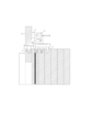
- FIG. 1 is a diagram illustrating a structure of a conventional filling tube.
- FIG. 13 is a diagram illustrating another structure of a conventional filling tube.
- FIG. 13 is a diagram illustrating another structure of a conventional filling tube.
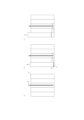
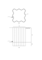
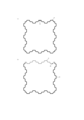
- FIG. 13 is a diagram for explaining the installation position of a conventional filling pipe.
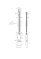
- 4A to 4C are diagrams illustrating the structure of a tip member of a filling tube according to the embodiment; 5A and 5B are diagrams for explaining the installation position of a filling tube according to the embodiment.
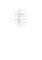
- 11 is a flowchart illustrating a construction procedure before sheet pile extraction.
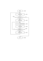
- 11 is a flowchart illustrating the flow of a simultaneous extraction and filling operation for a first set of sheet piles.
- a diagram illustrating the simultaneous extraction and filling operation of the first set of sheet piles.
- 11 is a flowchart illustrating the flow of simultaneous extraction and filling operations for the second and subsequent sets of sheet piles.
- Schematic diagram of the ground contamination containment configuration A diagram explaining the installation of filling pipes used when removing sheet piles installed to contain contaminated ground.
- the buried object is a sheet pile, and the removal of the sheet pile is described, but the buried object may be a pile or the like, and is not limited to a sheet pile.
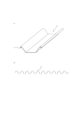
- the sheet pile 10 illustrated in FIG. 1(a) is a U-shaped steel sheet pile with a U-shaped cross-sectional shape. Below, the sheet pile 10 will be described as a U-shaped steel sheet pile, but the sheet pile 10 may be of a shape other than a U-shape.
- Liquid A and liquid B are supplied separately to the filling tube 30 by the supply pumps 40 and 41, respectively, and are mixed in the filling tube 30 just before being discharged.
- the filling material 31 is produced by mixing liquid A and liquid B, and is discharged from the discharge port.
- FIG. 5 shows an example of the connection between the filling pipe 30 and two supply pumps 40 and 41.
- the supply pumps 40 and 41 have two outlets for discharging liquid A and liquid B, respectively.
- the filling pipe 30 has two inlets for receiving liquid A and liquid B, respectively.
- cement sludge small solid pieces of cement (cement sludge) that have solidified and adhered to the inside of the mixer 42 fall off every time Liquid A is produced. If the top of the mixer 42 is not covered with a lid or the like, debris will enter the mixer 42. If cement sludge and debris are supplied to the supply pumps 40, 41 along with the produced Liquid A, the packing, valves, valve seats, pistons, etc. used in the supply pumps 40, 41 will be damaged.
- a mesh or strainer with many roughly square openings of about 0.6 to 1 mm can be used to remove cement residue, debris, etc.
- the drilling device includes a monitor, which is a drilling member having a sharp conical tip and a spiral groove, a rod-shaped rod to which the monitor is connected, and a clamping means for clamping the rod so that it can rotate and move up and down.
- the monitor is not limited to a conical tip with a sharp tip and a spiral groove, but may be a bit having a plurality of blades (tips) at the tip that cut and penetrate the ground.
- the filling pipe 60 having the structure shown in FIG. 6A can be preferably used under the following conditions. (a) When the N value is high, such as with gravel or boulders. (i) When a boring machine cannot be installed. (c) When sheet piles are reused and used multiple times on site. (e) When the filling pipe can be attached to the sheet pile in advance at a separate storage site.
- the filling tube 60-1 may be a steel tube, a tube made of plastic resin such as polyvinyl chloride, or one with a tip molded into various shapes.
- a tube molded into the shape of FIG. 6B and having an internal structure with a cylindrical plug 62-1 and an elastic body 63-1 inside may be used.
- the following are examples of solar panels that can use the filling tube 60-1 of FIG. 6B and FIG. 6C.
- the hole into which the filling pipe 60-1 is inserted is formed in advance using the above-mentioned drilling device, and the filling pipe 60-1 is installed by inserting it into the formed hole using the above-mentioned filling pipe installation device.
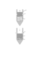
- the tip of the filling pipe 60-1 has a tapered shape that is easier to insert into the formed hole.
- the tip also has an outlet 61-1 that faces horizontally to the ground and allows the injection material to flow out into the pipe wall, and is internally provided with a cylindrical plug 62-1 and an elastic body 33 that is connected to one end of the plug 62-1 and can expand and contract in the length direction of the filling pipe 60-1.
- the outer wall surface of the plug 62-1 is adjacent to the inner wall surface of the filling pipe 60 so that no gaps are formed, and when no injection material is being supplied, the elastic body 63-1 stretches and rises in position, blocking the outlet 61-1 as shown in the upper part of Figure 6B.
- the elastic body 63-1 contracts due to the load, and the plug 62-1 descends, opening the outlet 61-1 as shown in the lower part of Figure 6B, and the continuously supplied filling material flows out into the surrounding soil as shown by the arrow.
- the elastic body 63-1 can be, for example, a coil spring.
- An O-ring can be provided between the plug 62-1 and the inner wall surface of the filling tube 60-1 to more reliably prevent leakage of the filling material.
- the filling tube 60-2 shown in Figure 6C does not have the plug 62-1 and elastic body 63-1, and the outlet 61-2 is composed of a first hole 61a-2 having a first diameter and a second hole 61b-2 connected to it and having a diameter larger than the first diameter, and the inside of the second hole 61b-2 is closed by a lid 64-2, which is a disk-shaped closing member.
- a lid 64-2 which is a disk-shaped closing member.
- a single lid 64-2 is used, but a double lid 64-2 may be used to improve the sealing and ensure that backflow is prevented.
- the inner lid can be made of plastic resin with a certain strength that can withstand the pressure of the backflowing soil and sand, and the outer lid can be made of silicone resin to improve sealing performance.
- a hole-drilling member 65-2 is attached to the tip of the filling tube 60-2, closing the tip.
- Figure 6C also shows the junction 66-2 where the two injection materials join.
- the construction device is equipped with a clamping means for clamping the filling pipe 60, and by adjusting the force with which the filling pipe 60 is clamped, the filling pipe 60 is lowered at a constant speed to insert the filling pipe 60 into the hole.
- a clamping means for clamping the filling pipe 60, and by adjusting the force with which the filling pipe 60 is clamped, the filling pipe 60 is lowered at a constant speed to insert the filling pipe 60 into the hole.
- the drilling device and the construction device do not have to be separate devices, and a device having both functions, such as a boring machine, may be used.
- the filling pipe 60 may be fixed to the buried object, or may be embedded in a hole excavated by a separate boring machine at the same time as or after excavation.
- the filling tube 60 includes rods 61, 62, which are two cylindrical pipes arranged in parallel.
- the rods 61, 62 form flow paths for separately supplying liquid A and liquid B. When supplying only one liquid, one rod is sufficient.
- the rods 61, 62 can be split into multiple pieces in the length direction as necessary, and can be connected by inserting them in the length direction using connecting members.
- a vibration prevention member 63 having a circular hole approximately equal to the outer diameter of the rods 61, 62 is attached to the connection point when connecting the rods 61, 62.
- the vibration prevention member 63 fixes the relative positions of the rods 61, 62 and prevents the rods 61, 62 from vibrating when the filling tube 60 is installed.
- An introduction member 64 having introduction ports for connecting each of the rods 61, 62 to each of the connecting tubes 50, 51 is provided at the top of the filling tube 60.
- the introduction member 64 and each of the connecting tubes 50, 51 are connected by inserting them lengthwise using the connecting members 52.
- a space connected to the inlets 68 and 69 is formed inside the upper member 66, and this space serves as a mixing chamber 70 for mixing the various liquids to produce the filler.
- the upper member 66 is provided with a discharge port 71 that connects the mixing chamber 70 to the external ground.
- the mixing chamber 70 has a cross section that is approximately circular with a constant diameter.
- the discharge port 71 extends perpendicular to the longitudinal direction of the rod, and discharges the filler in the direction in which the sheet piles 10 are installed.
- the lower member 67 is connected to the upper member 66 via a connecting member 72.
- the upper portion of the lower member 67 is roughly a rectangular parallelepiped, and the lower portion is cut off at an angle, with the thickness tapering toward the tip.
- the back surface of the lower member 67 is the contact surface that comes into contact with the sheet pile 10, and is formed flat so that it can be in close contact with the surface of the sheet pile 10.
- the discharge port 71 extends radially from the mixing chamber 70 at the center of the cross section of the filling pipe to the outer surface of the filling pipe 60, and a check valve 73 is provided inside to prevent backflow from the outside.
- the check valve 73 may be located anywhere within the discharge port, such as on the ground side, the mixing chamber side, or in the center.
- the check valve 73 is a valve whose valve body operates to prevent backflow due to the back pressure of the filling material in the mixing chamber 70, and there are lift and swing types depending on the type of valve body.
- the lift type is a type in which the valve body moves vertically to open and close
- the swing type is a type in which the valve body rotates like a door around a hinge as a fulcrum to open and close.
- a gap is created between the filling material and the check valve 73, so a sealing member (sealing material) 74 is provided to fill the gap and secure the check valve 73 so that it does not jump out when pushed by the filling material.
- the sealing material 74 is a hollow cylinder made of silicon, for example, and can be used by fitting it into the discharge port 71.
- the sealing material 74 generates frictional resistance between itself and the discharge port 71, and resists the filling material from pushing out the check valve 73. If the supply pressure of the filling material is (1 MPa or less), the sealing material can sufficiently secure the check valve 73.
- the tip member 65 of a conventional filling tube is configured as described above and is made up of three members: an upper member 66, a connecting member 72, and a lower member 67, and has a short tapered longitudinal length. This is because a hole is formed in the ground in the depth direction and the tube is inserted into the hole for installation, so as long as it is slightly tapered towards the tip, it can be inserted. Also, by configuring it from multiple members, the strength is reduced, but it is not pressed into the ground and can be disassembled into smaller pieces for easy transportation.
- the filling material is preferably discharged from as deep a position as possible, since it moves toward the ground surface and into the voids created by the extraction of the sheet piles 10, where pressure is low.
- the discharge outlet 71 is provided in the upper member 66, it will be at a position some distance away from the tip of the filling pipe 60.
- a filling pipe is installed adjacent to the sheet pile 10 using a drilling device and a construction device, and while the sheet pile 10 is being pulled out, filling material is discharged from the discharge port 71 of the filling pipe 60, filling the gaps created by the pulling out with filling material.
- the filling tube 60 can be installed in the gap where the filling material was filled before the filling material filling the last filled sheet pile 10 develops sufficient strength, allowing continuous construction to be performed. In this other embodiment to be described, it is easy to arbitrarily expand the construction range according to the properties of the ground at the site, without determining the construction range in advance.
- holes are formed for each set in this manner, and the filling pipes are inserted into the holes for installation.
- the quality of the ground varies from place to place, and drilling holes in the ground is not always easy. Hard ground or clay/silty ground is difficult to drill, and requires a considerable amount of time.
- drilling requires moving the drilling device and setting it in the designated position. Because the work of installing the filling pipes involves drilling holes in the ground, it takes time and also requires workers to perform the drilling work.
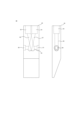
- the tip member 80 of the filling tube 30 will be described.
- the configuration other than the tip member 80 is the same as the conventional one.
- the tip member 80 may use the conventional tip member 65, but it would require manufacturing three members, and increasing the number of members would increase material costs, processing costs, and management costs, and would also reduce strength, so it is made from a single member.
- the filling tube 30 is installed by inserting it into the area filled with the filler 31 before it develops its strength.
- the tip of the conventional filling tubes 30, 60-1, 60-2 shown in Figures 6A, 6B, and 6C can be used, or a filling tube with a sharper tip can be used while retaining the configuration of the conventional filling tubes 30, 60-1, 60-2.
- the rest of the configuration can be the same as the conventional configuration, except that it is made up of a single member.
- the volume of the mixing chamber needs to be large in order to mix the two liquids sufficiently.
- the mixing chamber 70 is a space that extends significantly toward the tip from the discharge port 71.
- tip member 80 were made from a single member, its size would be too large, making it difficult to transport and manage.
- the internal space of the connecting pipes 86, 87 after they cross is a roughly triangular prism-shaped space, and because liquid A and liquid B are supplied so that they cross, they do not flow in layers, but collide well and are mixed and stirred, making it possible to sufficiently homogenize them in the short section from the crossing point to the connecting pipe 85.
- the mixing format shown in Figure 8 can also be used for the conventional filling pipes 30, 60-1, and 60-2 shown in Figures 6A, 6B, and 6C.
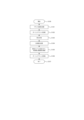
- step 200 The work starts from step 200, and the puller 24 is set in a predetermined position.
- step 201 one sheet pile 10 is pulled out to form a negative pressure void, and the filler 31 is discharged from the filling pipe 30, and the void 32 created by pulling out the sheet pile 10 is filled with the filler 31.
- this embodiment allows for a flexible pulling order of the sheet pile 10.
- the reason for this is presumably that pulling out the sheet pile 10 creates a negative pressure void, so that the discharge pressure of the filler from the filling pipe 31 and the negative pressure in the void work together to efficiently draw the filler 31 into the void.
- step 203 it is confirmed whether all of the sheet piles 10 in the first set have been pulled out. If not, the process returns to step 201 to pull out the next sheet pile 10. On the other hand, if all of the sheet piles 10 have been pulled out, the process proceeds to step 204, where water is supplied to the inside of the filling pipe 30 to clean the inside. Then, in step 205, the process of simultaneously pulling out and filling the first set of sheet piles 10 is completed.
- step 304 one sheet pile 10 is pulled out, and at the same time, filler material 31 is discharged from the filling tube 30, and the gap 32 created by pulling out the sheet pile 10 is filled with the filler material 31.
- step 305 the puller 24 is moved to pull out the next sheet pile 10.
- step 306 it is confirmed whether all the sheet piles 10 in that set have been pulled out. If not, the process returns to step 304 and the next sheet pile 10 is pulled out.
- step 302 If all sheet piles 10 have been pulled out in step 302, proceed to step 308 and end the simultaneous pulling and filling operation.
- the filling pipe 30 is collected, and in order to extract the third set of sheet piles 10, the filling pipe 30 is similarly installed at the filling location of the second set, and the third set of sheet piles 10 is extracted.
- multiple sheet piles 10 are connected by joints 11, and in addition to preventing the collapse of soil and sand on slopes and embankments, they can also be used to divide areas of the ground and contain the ground, for example to prevent contaminants from moving from one area to another.
- the sheet pile 10 can be removed while maintaining its containment function. As a result, the sheet pile 10 can be reused.
- the third and subsequent sets of sheet piles 10 can be pulled out while the filling material 31 is being discharged from the filling tube 30.
- a wall made of the hardened filling material 31 can be constructed, and the thickness of the wall is sufficient to contain the pollutants.
- the filling pipe 30 can be easily installed, shortening the construction period and reducing the number of workers required.
- the number of times holes need to be drilled using drilling members is reduced, which reduces wear on the drilling members. This makes it possible to shorten the construction period for the removal of buried objects and the containment of contaminated ground.
- the configuration of the present invention can be used to prevent initial displacement of the sheet piles when driving them into the ground while filling them with filler, as described in JP 2023-54602 A, for example.
- filler is filled at the same time as the sheet piles are driven, continuous displacement of the sheet piles after driving them can be prevented, and deformation and collapse of the voids that are generated when the sheet piles are pulled out can also be prevented.
- the present invention is not limited to the above-mentioned embodiments, and can be modified within the scope of what a person skilled in the art can conceive, such as other embodiments, additions, modifications, deletions, etc., and any aspect is within the scope of the present invention as long as it provides the functions and effects of the present invention.
Landscapes
- Engineering & Computer Science (AREA)
- Structural Engineering (AREA)
- Life Sciences & Earth Sciences (AREA)
- General Life Sciences & Earth Sciences (AREA)
- Mining & Mineral Resources (AREA)
- Paleontology (AREA)
- Civil Engineering (AREA)
- General Engineering & Computer Science (AREA)
- Chemical & Material Sciences (AREA)
- Composite Materials (AREA)
- Consolidation Of Soil By Introduction Of Solidifying Substances Into Soil (AREA)
Abstract
Description
埋設物を撤去する方法であって、第1の埋設物が埋設された地盤内に充填管を設置する工程と、前記第1の埋設物を引抜き、引抜きにより形成された負圧の空隙に前記第1の埋設物から離間した位置の前記充填管から充填材を異なる性質の地中構造の界面または境界面を通して負圧により誘引して前記空隙に前記充填材を充填する工程と、前記充填材のゲル化後に地表まで延びた前記充填材の壁を形成する工程とを含む、埋設物を撤去する方法が提供される。
(ア)砂礫や玉石などN値が高い場合。
(イ)ボーリングマシンが設置できない場合。
(ウ)シートパイルを転用して、複数回現場で使う場合。
(エ)別の置き場で充填管を事前にシートパイルに取付することができる場合。
ここで、充填管60-1は、鋼管や、ポリ塩化ビニル管等のプラスチック樹脂からなる管のほか、先端部を様々な形状に成形したものを用いることができる。例えば、図6Bの形状に外形を成形し、内部に円筒状の栓62-1および弾性体63-1を備える内部構造としたものを用いることができる。なお、図6B、図6Cの充填管60-1を使用できる太陽としては、以下の場合を挙げることができる。
(ア)すでにシートパイルが打設済みの場合。
(イ)同時引抜き充填工法で対応ができる現場の場合。
11…継手
20…サイレントパイラー
21…チャック
22…昇降装置
23…掴み部
24…引抜機
25…ボーリングマシン
30…充填管
31…充填材
32…空隙
40、41…供給ポンプ
42、43…ミキサー
44~47…容器
48…水中ポンプ
49…発電機
50、51…接続管
60…充填管
61、62…ロッド
63…ブレ止め部材
64…導入部材
65…先端部材
66…上部部材
67…下部部材
68、69…導入口
70…混合室
71…吐出口
72…接続部材
73…逆止弁
74…シール材
75…汚染土壌
76…粘土層(支持層)
77…連壁
80…先端部材
81、82…吐出口
83、84…導入口
85…連結管
86、87…接続管
Claims (10)
- 埋設物を撤去する方法であって、
第1の埋設物が埋設された地盤内に充填管を設置する工程と、
前記第1の埋設物を引抜き、引抜きにより形成された負圧の空隙に前記第1の埋設物から離間した位置の前記充填管から充填材を異なる性質の地中構造の界面または境界面を通して負圧により誘引して前記空隙に前記充填材を充填する工程と、
前記充填材のゲル化後に地表まで延びた前記充填材の壁を形成する工程と
を含む、埋設物を撤去する方法。 - 前記第1の埋設物に隣接する第2の埋設物を引抜き、前記第2の埋設物の引抜きにより形成された第2の空隙に前記境界層を通して前記充填材を充填する工程と、
前記第1の埋設物および前記第2の埋設物の位置に対応する連続した前記充填材の連壁を形成する工程と
を含む、請求項1に記載の埋設物を撤去する方法。 - 引抜かれた前記第2の埋設物が形成した空隙内に充填材のゲルの強度が発現する前に、前記充填材を注入するための充填管を挿入して設置する工程と、
前記充填管から離れた位置に埋設された第3の埋設物を引抜く工程と、
事前に第2の充填管を設置することなく、前記第3の埋設物の位置に前記充填材を充填して前記壁を延長する工程と
を含む、請求項1に記載の埋設物を撤去する方法。 - 前記設置する工程は、建込装置を吊し上げた状態で、前記建込装置が挟持した前記充填管を降下させることにより、前記充填箇所に挿入する、請求項3に記載の埋設物の撤去方法。
- 少なくとも前記第2の埋設物を引抜いた後に、前記充填管を回収する工程を含む、請求項1に記載の埋設物の撤去方法。
- 汚染地盤の封じ込め方法であって、
複数の埋設物を、汚染物質を含む領域と汚染物質を含まない領域の境界に設置する工程と、
削孔した地盤の孔内に第1の充填管を設置する工程と、
第1の埋設物を1つずつ引抜きながら負圧の空隙を形成し、引抜かれる埋設物から離間して設置された前記充填管から充填材を吐出して、異なる性質の地中構造の界面または境界面を通して前記負圧の空隙に誘導して充填する工程と、
第2の充填管に隣接する第2の埋設物を引抜きながら、設置された前記第2の充填管から充填材を吐出する工程と
を含む、汚染地盤の封じ込め方法。 - 前記設置する工程は、建込装置を吊し上げた状態で、前記建込装置が挟持した前記充填管を降下させることにより、前記充填箇所に挿入する、請求項6に記載の汚染地盤の封じ込め方法。
- さらに、前記第1の埋設物を引抜き、充填が完了した後、前記充填材のゲルの強度が発現する前に、前記第2の充填管を前記強度が発現する前の前記充填材に挿入して設置する工程
を含む、請求項6または7に記載の汚染地盤の封じ込め方法。 - 埋設物撤去システムであって、
硬化性組成物および促進剤を加圧して供給する第1の2液供給装置と、
前記2液供給装置から前記促進剤および前記硬化性組成物を別々に供給するための複数の接続管と、
支持層から上の地盤内に設置され、前記促進剤および前記硬化性組成物を内部混合して充填材を形成するための混合室を備える注入管と、
前記地盤に埋設された埋設物が引抜かれて形成された負圧の空隙にまで、前記埋設物と前記地盤との境界層または支持層と前記地盤との境界層を通して流動し、ゲル化後に地表まで延びる連壁を形成するための充填材と
を含む、埋設物撤去システム。 - さらに前記硬化性組成物および前記促進剤を加圧して供給する第2の2液供給装置を備え、
前記第2の2液供給装置の圧力および供給量を前記第1の2液供給装置からの前記効果組成物および前記促進剤の特性に応じた圧力損失に相当して制御する手段を備える請求項9に記載の埋設物撤去システム。
Priority Applications (3)
| Application Number | Priority Date | Filing Date | Title |
|---|---|---|---|
| PCT/JP2023/021393 WO2024252627A1 (ja) | 2023-06-08 | 2023-06-08 | 埋設物の撤去方法、汚染地盤の封じ込め方法、および埋設物撤去システム |
| EP23940725.7A EP4726106A1 (en) | 2023-06-08 | 2023-06-08 | Buried object removal method, contaminated ground containment method, and buried object removal system |
| JP2025525872A JPWO2024252627A1 (ja) | 2023-06-08 | 2023-06-08 |
Applications Claiming Priority (1)
| Application Number | Priority Date | Filing Date | Title |
|---|---|---|---|
| PCT/JP2023/021393 WO2024252627A1 (ja) | 2023-06-08 | 2023-06-08 | 埋設物の撤去方法、汚染地盤の封じ込め方法、および埋設物撤去システム |
Publications (1)
| Publication Number | Publication Date |
|---|---|
| WO2024252627A1 true WO2024252627A1 (ja) | 2024-12-12 |
Family
ID=93795665
Family Applications (1)
| Application Number | Title | Priority Date | Filing Date |
|---|---|---|---|
| PCT/JP2023/021393 Ceased WO2024252627A1 (ja) | 2023-06-08 | 2023-06-08 | 埋設物の撤去方法、汚染地盤の封じ込め方法、および埋設物撤去システム |
Country Status (3)
| Country | Link |
|---|---|
| EP (1) | EP4726106A1 (ja) |
| JP (1) | JPWO2024252627A1 (ja) |
| WO (1) | WO2024252627A1 (ja) |
Citations (4)
| Publication number | Priority date | Publication date | Assignee | Title |
|---|---|---|---|---|
| JP2013159960A (ja) * | 2012-02-06 | 2013-08-19 | Takenaka Komuten Co Ltd | シートパイル引抜部充填方法 |
| JP2020125613A (ja) | 2019-02-04 | 2020-08-20 | 大地 山下 | 土留部材の撤去方法および汚染土壌の封じ込め方法 |
| JP2021098975A (ja) * | 2019-12-20 | 2021-07-01 | 大地 山下 | 埋設物の撤去方法 |
| JP2023054602A (ja) | 2021-10-04 | 2023-04-14 | 大地 山下 | 埋設物の施工方法 |
-
2023
- 2023-06-08 EP EP23940725.7A patent/EP4726106A1/en active Pending
- 2023-06-08 WO PCT/JP2023/021393 patent/WO2024252627A1/ja not_active Ceased
- 2023-06-08 JP JP2025525872A patent/JPWO2024252627A1/ja active Pending
Patent Citations (4)
| Publication number | Priority date | Publication date | Assignee | Title |
|---|---|---|---|---|
| JP2013159960A (ja) * | 2012-02-06 | 2013-08-19 | Takenaka Komuten Co Ltd | シートパイル引抜部充填方法 |
| JP2020125613A (ja) | 2019-02-04 | 2020-08-20 | 大地 山下 | 土留部材の撤去方法および汚染土壌の封じ込め方法 |
| JP2021098975A (ja) * | 2019-12-20 | 2021-07-01 | 大地 山下 | 埋設物の撤去方法 |
| JP2023054602A (ja) | 2021-10-04 | 2023-04-14 | 大地 山下 | 埋設物の施工方法 |
Non-Patent Citations (1)
| Title |
|---|
| See also references of EP4726106A1 |
Also Published As
| Publication number | Publication date |
|---|---|
| EP4726106A1 (en) | 2026-04-15 |
| JPWO2024252627A1 (ja) | 2024-12-12 |
Similar Documents
| Publication | Publication Date | Title |
|---|---|---|
| JP5339498B2 (ja) | せん断補強材の定着方法 | |
| JP2008231810A (ja) | 地下構造物の施工法 | |
| CN108396780B (zh) | 一种既有检查井改建方法 | |
| KR101045625B1 (ko) | Cip 공법을 이용한 지하 연속 흙막이벽 구축공법 | |
| US20060275087A1 (en) | Soil extraction/grouting device | |
| JP2025156530A (ja) | 埋設物の施工方法 | |
| JP5840891B2 (ja) | 土留部材の撤去方法 | |
| CN108149682A (zh) | 一种注浆护筒装置及采用该护筒装置的桩基成孔施工方法 | |
| JP2015229860A (ja) | 掘削孔内での地下水移動の制御方法、グラウトの充填方法、貯水手段 | |
| WO2024252627A1 (ja) | 埋設物の撤去方法、汚染地盤の封じ込め方法、および埋設物撤去システム | |
| JP7277157B2 (ja) | 土留部材の撤去方法および汚染土壌の封じ込め方法 | |
| JP6615494B2 (ja) | 土留部材の撤去方法 | |
| CN105887904A (zh) | 岩溶地区深基坑外侧溶腔填充施工方法 | |
| JP7073326B2 (ja) | 埋設物の撤去方法 | |
| CN204626416U (zh) | 一种自钻进钢管桩连续墙 | |
| US20170030041A1 (en) | Systems, methods and apparatus for slurry wall construction incorporating sheet pilings | |
| JP6361045B2 (ja) | 土留部材撤去方法 | |
| JPH09209361A (ja) | ピット構造物内での杭打ち方法 | |
| JP6273603B2 (ja) | 土留め工法 | |
| KR100958378B1 (ko) | 파일 시공설비의 주입장치 | |
| EP1964981A1 (en) | Reinforcement elements for in-situ cast walls and method to excavate in situ cast walls | |
| JP2022020402A (ja) | 埋設物の施工方法 | |
| CN108005079A (zh) | 植入式预制桩注浆装置和植入式注浆工艺 | |
| JP2024072214A (ja) | 農業用水管の施工方法 | |
| JP2008101373A (ja) | 土留め工事用硬化剤注入管および土留め工法 |
Legal Events
| Date | Code | Title | Description |
|---|---|---|---|
| 121 | Ep: the epo has been informed by wipo that ep was designated in this application |
Ref document number: 23940725 Country of ref document: EP Kind code of ref document: A1 |
|
| ENP | Entry into the national phase |
Ref document number: 2025525872 Country of ref document: JP Kind code of ref document: A |
|
| WWE | Wipo information: entry into national phase |
Ref document number: 2023940725 Country of ref document: EP |
|
| NENP | Non-entry into the national phase |
Ref country code: DE |
|
| ENP | Entry into the national phase |
Ref document number: 2023940725 Country of ref document: EP Effective date: 20260108 |
|
| ENP | Entry into the national phase |
Ref document number: 2023940725 Country of ref document: EP Effective date: 20260108 |
|
| ENP | Entry into the national phase |
Ref document number: 2023940725 Country of ref document: EP Effective date: 20260108 |
|
| ENP | Entry into the national phase |
Ref document number: 2023940725 Country of ref document: EP Effective date: 20260108 |
|
| ENP | Entry into the national phase |
Ref document number: 2023940725 Country of ref document: EP Effective date: 20260108 |
|
| WWP | Wipo information: published in national office |
Ref document number: 2023940725 Country of ref document: EP |