WO2024252562A1 - 基板生産プログラムの最適化方法、最適化装置および最適化システム - Google Patents
基板生産プログラムの最適化方法、最適化装置および最適化システム Download PDFInfo
- Publication number
- WO2024252562A1 WO2024252562A1 PCT/JP2023/021172 JP2023021172W WO2024252562A1 WO 2024252562 A1 WO2024252562 A1 WO 2024252562A1 JP 2023021172 W JP2023021172 W JP 2023021172W WO 2024252562 A1 WO2024252562 A1 WO 2024252562A1
- Authority
- WO
- WIPO (PCT)
- Prior art keywords
- optimization
- conditions
- production program
- component
- execution
- Prior art date
- Legal status (The legal status is an assumption and is not a legal conclusion. Google has not performed a legal analysis and makes no representation as to the accuracy of the status listed.)
- Ceased
Links
Images






Classifications
-
- G—PHYSICS
- G06—COMPUTING OR CALCULATING; COUNTING
- G06F—ELECTRIC DIGITAL DATA PROCESSING
- G06F9/00—Arrangements for program control, e.g. control units
- G06F9/06—Arrangements for program control, e.g. control units using stored programs, i.e. using an internal store of processing equipment to receive or retain programs
- G06F9/46—Multiprogramming arrangements
- G06F9/50—Allocation of resources, e.g. of the central processing unit [CPU]
- G06F9/5061—Partitioning or combining of resources
- G06F9/5066—Algorithms for mapping a plurality of inter-dependent sub-tasks onto a plurality of physical CPUs
-
- G—PHYSICS
- G06—COMPUTING OR CALCULATING; COUNTING
- G06F—ELECTRIC DIGITAL DATA PROCESSING
- G06F9/00—Arrangements for program control, e.g. control units
- G06F9/06—Arrangements for program control, e.g. control units using stored programs, i.e. using an internal store of processing equipment to receive or retain programs
- G06F9/46—Multiprogramming arrangements
- G06F9/50—Allocation of resources, e.g. of the central processing unit [CPU]
- G06F9/5005—Allocation of resources, e.g. of the central processing unit [CPU] to service a request
- G06F9/5027—Allocation of resources, e.g. of the central processing unit [CPU] to service a request the resource being a machine, e.g. CPUs, Servers, Terminals
-
- G—PHYSICS
- G06—COMPUTING OR CALCULATING; COUNTING
- G06F—ELECTRIC DIGITAL DATA PROCESSING
- G06F9/00—Arrangements for program control, e.g. control units
- G06F9/06—Arrangements for program control, e.g. control units using stored programs, i.e. using an internal store of processing equipment to receive or retain programs
- G06F9/46—Multiprogramming arrangements
- G06F9/50—Allocation of resources, e.g. of the central processing unit [CPU]
- G06F9/5061—Partitioning or combining of resources
- G06F9/5072—Grid computing
Definitions
- This invention relates to technology for optimizing production programs that stipulate the conditions for mounting components on boards on a component mounting line.
- a technology is known in which a component mounting line is operated in accordance with conditions defined in a production program that indicates the execution of a specified production plan, and the line mounts components onto the boards, thereby producing the boards planned in the production plan.
- the conditions defined in the production program include the types of components to be set on the component mounting line, the positions at which the components are set on the component mounting line, or the order in which the components are mounted on the boards.
- the production program is generally optimized. In this case, it is important to reduce the calculation time required to optimize the production program.
- Patent Document 1 multiple algorithms for optimization are prepared, and the same production data is sent to multiple computers, and each computer is made to optimize the same production data using a different algorithm.
- each computer perform optimization in parallel using different algorithms, it is possible to obtain an optimized solution using the most suitable algorithm out of the multiple algorithms in a short period of time.
- Cited Document 1 causes multiple computers to each optimize the same production data. Therefore, when optimizing a production program for executing a specified production plan using this technology, multiple computers optimize the same production program.
- This type of method has room for improvement from the following two perspectives. First, there is room for improvement in shortening the calculation time required to optimize a production program, since each of the multiple computers requires calculation time to optimize the entire production program. Second, since multiple computers are used to optimize the same production program, it was necessary to prepare many computers; the former is an inefficient use of the resource of time, and the latter is an inefficient use of the resource of equipment (computers). Therefore, there was a need to make effective use of at least one of the resources.
- This invention was developed in consideration of the above problems, and aims to enable efficient use of resources (computing time or equipment) required to optimize production programs.
- the method for optimizing a board production program includes the steps of: acquiring optimization target data including a production program that specifies the conditions for mounting components on a board in a component mounting line; executing an allocation process that allocates N different pieces of element data (N is an integer equal to or greater than 2) included in the optimization target data to Q arithmetic units (Q is an integer equal to or greater than 2 and equal to or less than N); and executing a parallel optimization process in which the Q arithmetic units execute in parallel calculations to optimize the element data that has been assigned to them in the allocation process.
- N is an integer equal to or greater than 2
- Q is an integer equal to or greater than 2 and equal to or less than N
- the optimization device for a board production program includes a production program acquisition unit that acquires optimization target data including a production program that specifies the conditions for mounting components on a board in a component mounting line, an allocation process execution unit that assigns N different pieces of element data (N is an integer equal to or greater than 2) included in the optimization target data to Q arithmetic units (Q is an integer equal to or greater than 2 and equal to or less than N), and a parallel optimization process execution unit that causes each of the Q arithmetic units to execute in parallel a calculation that optimizes the assigned element data.
- N is an integer equal to or greater than 2
- Q is an integer equal to or greater than 2 and equal to or less than N
- parallel optimization process execution unit that causes each of the Q arithmetic units to execute in parallel a calculation that optimizes the assigned element data.
- the optimization system for a board production program comprises a management calculation device and a plurality of execution calculation devices.
- the management calculation device has a production program acquisition unit that acquires optimization target data including a production program that specifies the conditions for mounting components on a board in a component mounting line, and an assignment process execution unit that assigns N different pieces of element data (N is an integer equal to or greater than 2) included in the optimization target data to Q execution calculation devices (Q is an integer equal to or greater than 2 and equal to or less than N) among the plurality of execution calculation devices, and each of the Q execution calculation devices executes calculations in parallel to optimize the assigned element data.
- N is an integer equal to or greater than 2
- Q is an integer equal to or greater than 2 and equal to or less than N
- N is an integer equal to or greater than 2 pieces of element data included in the optimization target data, including the production program, are assigned to Q arithmetic units (execution arithmetic units). Each of the Q arithmetic units then executes in parallel an operation to optimize the assigned element data.
- the present invention decomposes the optimization target data, including the production program, into N pieces of element data, and has the Q arithmetic units execute the optimization of the N pieces of element data in parallel.
- it is possible to efficiently utilize the resources (operation time) required for optimizing the production program i.e., to shorten the operation time required for optimizing the production program.
- the optimization method for the board production program may be configured such that, in the allocation process, out of M element conditions (M is an integer equal to or greater than N) included in the conditions defined by the production program, N element conditions capable of executing an operation to optimize each of the element conditions in parallel are assigned to Q arithmetic devices as N element data, and in the parallel optimization process, the Q arithmetic devices execute in parallel the operation to optimize the element conditions assigned to them in the allocation process.
- N element conditions (M is an integer equal to or greater than 2) included in the conditions defined by the production program
- M is an integer equal to or greater than 2
- M is an integer equal to or greater than 2 and equal to or less than M
- Q arithmetic devices execution arithmetic devices
- each of the Q arithmetic devices executes an operation to optimize the assigned element conditions in parallel.
- the conditions defined by the production program are decomposed into M element conditions, and the optimization of N of the M element conditions is executed in parallel by Q arithmetic devices. As a result, it is possible to reduce the calculation time required for optimizing the production program.
- the optimization method for the board production program may be configured so that, of the M element conditions, a calculation for optimizing (M-N) element conditions that are different from the N element conditions is executed at a timing different from that of the parallel optimization process.
- the calculation for optimizing (M-N) element conditions can be executed at an appropriate timing.
- the component mounting line may also have multiple set positions for setting components
- the production program may define conditions for executing N setup groups, and in each of the N setup groups, components are mounted in sequence on multiple types of boards after the setup work of setting the components at the set positions is performed, and the allocation process may be configured to treat the conditions for executing the setup groups as element conditions and allocate the N element conditions corresponding to the N setup groups to Q arithmetic units.
- the conditions defined in the production program are decomposed into M element conditions including the N element conditions corresponding to the N setup groups.
- the optimization of the N element conditions is then performed in parallel by the Q arithmetic units. As a result, it is possible to reduce the calculation time required for optimizing the production program.
- the component mounting line may have multiple set positions for setting components
- the production program may define conditions for executing a setup group, and after the setup work of setting components at the set positions is executed in the setup group, the components set at the set positions are mounted in order on N types of boards, and in the allocation process, a condition indicating the order in which components are mounted on one type of board is treated as an element condition, and N element conditions corresponding to the N types of boards are allocated to Q arithmetic devices.
- the conditions defined in the production program are decomposed into M element conditions including N element conditions corresponding to the N types of boards. Then, optimization of the N element conditions is executed in parallel by the Q arithmetic devices. As a result, it is possible to reduce the calculation time required for optimizing the production program.
- the optimization method for a board production program may also be configured to include a step of executing, before the allocation process, a component position optimization process that optimizes the components to be set in the set positions during setup work; a step of waiting for the optimization of N element conditions executed by Q arithmetic devices to be completed; a step of determining, upon completion of the optimization of the N element conditions, whether or not it is necessary to re-execute the component position optimization process based on the results of the optimization of the N element conditions; and, upon determining that it is necessary to re-execute the component position optimization process, executing the component position optimization process, the allocation process, and the parallel optimization process.
- the component mounting line may also be equipped with N component mounters arranged in series
- the production program may specify conditions for transporting a board to the N component mounters in sequence and for each of the N component mounters to mount components on the board
- the allocation process may be configured to treat the conditions indicating the order in which one component mounter mounts components on the board as element conditions, and to allocate the N element conditions corresponding to the N component mounters to the Q arithmetic units.
- the conditions specified in the production program are decomposed into M element conditions including the N element conditions corresponding to the N component mounters.
- the optimization of the N element conditions is then performed in parallel by the Q arithmetic units. As a result, it is possible to reduce the calculation time required for optimizing the production program.
- the optimization method for a board production program may also be configured to include a step of executing a component position optimization process that optimizes the components to be set on N component mounters before the allocation process, a step of waiting for the optimization of N element conditions executed by Q arithmetic devices to be completed, a step of determining whether or not the component position optimization process needs to be executed again based on the results of the optimization of the N element conditions when the optimization of the N element conditions is completed, and a step of executing the component position optimization process, the allocation process, and the parallel optimization process when it is determined that the component position optimization process needs to be executed again.
- the optimization method for a board production program may be configured so that the production program is obtained by receiving optimization target data transmitted from a specified terminal device, and the Q arithmetic devices are Q cloud servers.
- the optimization method for a board production program may be configured so that the production program is obtained by receiving optimization target data transmitted from a specified terminal device, and the Q arithmetic devices are Q servers connected to the terminal device via a local area network.
- the optimization method for board production programs may be configured such that in the allocation process, N different production programs included in the optimization target data are assigned to Q arithmetic units as N pieces of element data, and in the parallel optimization process, the Q arithmetic units execute in parallel calculations to optimize the production programs assigned to them in the allocation process.
- N different production programs (N is an integer greater than or equal to 2 and less than or equal to M) are assigned to Q arithmetic units.
- each of the Q arithmetic units executes in parallel calculations to optimize the assigned production program.
- multiple arithmetic units are not used to optimize the same production program, but are used to optimize different production programs. As a result, it is possible to efficiently use the resources (facilities) required for optimizing the production programs.
- the present invention makes it possible to reduce the calculation time required to optimize a production program.
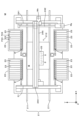
- FIG. 1 is a block diagram that illustrates a schematic diagram of an optimization system according to the present invention and a component mounting line that executes a production program optimized by the optimization system.
- FIG. 1 is a plan view illustrating a schematic configuration of an example of a component mounter.
- 4 is a flow chart showing an example of control executed by a local server for optimizing a production program.
- 4 is a flowchart showing a first example of control executed by the optimization system for optimizing a production program.
- 5 is a timing chart showing a first example of the operation executed according to the flowchart of FIG. 4 .
- 5 is a timing chart showing a first example of the operation executed according to the flowchart of FIG. 4 .
- FIG. 5 is a timing chart showing a second example of the operation executed according to the flowchart of FIG. 4 .
- 5 is a timing chart showing a second example of the operation executed according to the flowchart of FIG. 4 .
- 6 is a flowchart showing a second example of control executed by the optimization system for optimizing a production program.
- FIG. 8 is a diagram showing a first example of a timing chart that illustrates the content of calculations executed according to the flowchart of FIG. 7.
- 1 is a timing chart showing the operation of mounting components E on three types K(a) to K(c) in sequence on a component mounting line LN.
- 1 is a timing chart showing the operation of mounting components E on three types K(a) to K(c) in sequence on a component mounting line LN.
- FIG. 8 is a diagram showing a second example of a timing chart that illustrates the content of calculations executed according to the flowchart of FIG. 7 .
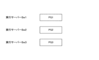
- FIG. 13 is a diagram showing an example of a timing chart for executing optimization of a plurality of production programs in parallel.
- FIG. 1 is a block diagram that shows a schematic diagram of an optimization system according to the present invention and a component mounting line that executes a production program optimized by the optimization system.
- the component mounting line LN is installed on the user's site PR, and is equipped with multiple component mounters M (three in the example of FIG. 1) lined up in series in the X direction (horizontal direction). Boards B (FIG. 2) are loaded into these component mounters M in sequence, and each component mounter M mounts components E (FIG. 2) on the loaded board B. In this way, the multiple component mounters M share the task of mounting components E on the same board B, and produce boards B with components mounted on them.
- a local server Sl and a local area network NW are provided on the user's site PR, and the local area network NW interconnects the multiple component mounters M and the local server Sl.
- the local server Sl is a server computer, and manages the component mounting line LN.
- the local server Sl manages the component mounting line LN based on a production program PG that causes the component mounting line LN to execute a production plan indicating the production of a specified number of boards of a specified variety.
- the multiple component mounters M on the component mounting line LN mount components E on the board B by operating in accordance with the production program PG.
- the optimization system SY that optimizes the production program PG is installed in a location separate from the site PR, in other words, on the cloud.
- This optimization system SY comprises a management server Sm, which is a computer that functions as a cloud server, and multiple execution servers Se1, Se2, Se3, ....
- the management server Sm manages the multiple execution servers Se1, Se2, Se3, ... and communicates with a local server Sl via the Internet communication network. The operation of this optimization system SY will be described later.
- FIG. 2 is a plan view showing a schematic configuration of an example of a component mounter.
- This component mounter M mounts small piece-like electronic components E such as integrated circuits, transistors, and capacitors on a board B.
- the component mounter M is equipped with a transport unit 21 that transports the board B in the X direction (board transport direction).
- This transport unit 21 has a pair of conveyors 211 arranged in parallel in the X direction, and transports the board B in the X direction by the conveyors 211.
- the spacing between these conveyors 211 can be changed in the Y direction (width direction) perpendicular to the X direction, and the transport unit 21 adjusts the spacing between the conveyors 211 according to the width of the board B being transported.
- This transport unit 21 transports the board B from the upstream side in the X direction, which is the board transport direction, to a specified work position 212, and transports the board B on which components E have been mounted at the work position 212 from the work position 212 downstream in the X direction.
- This component mounter M is provided with a total of four component supply carts 22, and specifically, two component supply carts 22 are lined up in the X direction on each side of the transport section 21 in the Y direction.
- multiple tape feeders 23 are lined up in the X direction, and multiple component supply reels are arranged corresponding to the multiple tape feeders 23.
- a component storage tape is wound around the component supply reel.
- This component storage tape has multiple pockets arranged in a row, and components E are stored in each pocket.
- Each tape feeder 23 has a component supply position 231 at its tip on the transport section 21 side in the Y direction, and supplies components E in the component storage tape to the component supply position 231 by intermittently sending the component storage tape pulled out from the component supply reel to the transport section 21 side.
- Each part supply cart 22 has multiple feeder set positions F23 aligned in the X direction.
- a tape feeder 23 can be removably set at the feeder set positions F23. When the tape feeder 23 is set at the tape feeder 23, the part E attached to the tape feeder 23 is set at the feeder set position F23.
- the component mounter M is provided with a pair of Y-axis rails 241 extending in the Y direction, a Y-axis ball screw 242 extending in the Y direction, and a Y-axis motor My that rotates and drives the Y-axis ball screw 242.
- the X-axis rail 244 is supported by the pair of Y-axis rails 241 so as to be movable in the Y direction and is fixed to the nut of the Y-axis ball screw 242.
- the X-axis rail 244 is attached with an X-axis ball screw 245 extending in the X direction and an X-axis motor Mx that rotates and drives the X-axis ball screw 245.
- the component mounter M is provided with a head unit 25, which is supported by the X-axis rail 244 so as to be movable in the X direction and is fixed to the nut of the X-axis ball screw 245. Therefore, the Y-axis motor My can rotate the Y-axis ball screw 242 to move the head unit 25 in the Y direction, or the X-axis motor Mx can rotate the X-axis ball screw 245 to move the head unit 25 in the X direction.
- the head unit 25 is an inline type having multiple mounting heads 5 arranged in a line in the X direction.
- the specific configuration of the head unit 25 is not limited to the example in Figure 1, and the head unit 25 may be a rotary type having multiple mounting heads 5 arranged in a circular pattern.
- the number of mounting heads 5 held by the head unit 25 is not limited to multiple, and may be a single number.
- a nozzle is removably attached to the bottom end of each mounting head 5, and the mounting head 5 picks up the component E using the nozzle.
- the mounting head 5 is moved by the X-axis motor Mx and the Y-axis motor My, so that the nozzle 51 of the mounting head 5 faces the component E supplied to the component supply position 231 from above.
- the nozzle 51 is lowered to bring the nozzle 51 into contact with the upper surface of the component E supplied to the component supply position 231, and then the nozzle 51 picks up the component E from the component supply position 231 by raising the nozzle 51.
- the mounting head 5 is moved by the X-axis motor Mx and the Y-axis motor My, so that the component E to be picked up by the nozzle 51 of the mounting head 5 faces the land of the board B from above.
- the angle of the component E to be picked up by the nozzle 51 with respect to the land is adjusted, and the nozzle 51 is lowered to place the component E on the land of the board B.
- the production program PG specifies the conditions for mounting components E on the board B on the component mounting line LN in order to execute a predetermined production plan on the component mounting line LN.
- This production program PG includes various conditions, including at least: component position conditions...conditions that specify the positions (specifically, the feeder set positions F23) at which various components E are set on each component mounter M; mounting order conditions...conditions that specify the components E to be mounted on each mounting point on the board B and the order in which the components E are mounted on each mounting point.
- at least the component position conditions and the mounting order conditions are optimized in order to shorten the time required to complete the execution of the production plan.
- the production program PG specifies the conditions (overall conditions) required for the component mounting line LN to execute the production plan, and these overall conditions can be considered to be a collection of multiple element conditions.
- the overall conditions specified by the production program PG are a collection of component position conditions and mounting order conditions, etc., and these overall conditions can be considered to be separated into element conditions called component position conditions and element conditions called mounting order conditions.
- the purpose of separating into multiple element conditions in this way is to reduce the calculation time required to optimize the production program PG by performing optimization of two or more element conditions in parallel. Note that there are variations in how the element conditions can be considered, and they are optional, as will be specifically shown later.
- FIG. 3 is a flowchart showing an example of control executed by a local server for optimizing a production program.
- the local server Sl creates an optimization execution list in response to user operations on the UI (User Interface).
- This optimization execution list indicates one or more production programs PG for which the user requests optimization execution.
- step S102 the local server S1 determines whether an execution command for optimizing the production program PG has been input by operating the UI (step S102).
- the local server S1 requests cloud authentication from the user (step S103). Specifically, the local server S1 performs cloud authentication by inputting the user's ID and password via the UI.
- the local server Sl uploads the production programs PG included in the optimization execution list to the management server Sm of the optimization system SY. Then, when the local server Sl confirms that optimization of the production programs PG in the optimization system SY is complete ("YES" in step S105), it downloads the optimized production programs PG from the management server Sm (step S106) and displays the results on the display (step S107). Note that when multiple production programs PG have been uploaded, they may be downloaded in order starting with the production programs PG for which optimization has been completed, or they may be downloaded all at once after optimization of all production programs PG has been completed.
- FIG. 4 is a flowchart showing a first example of control executed by the optimization system to optimize a production program.
- the management server Sm of the optimization system SY receives a production program PG uploaded from the local server Sl, it determines that optimization of the production program PG has been requested ("YES" in step S201).
- the optimization system SY determines the number of execution servers Se required to optimize the production program PG based on the results of analyzing the number of element conditions contained in the production program PG (step S202). As a result, if the number of currently activated execution servers Se is insufficient for the number required to optimize the production program PG, the local server Sl activates the missing execution servers Se (step S203).
- Steps S204 to S206 are executed according to the number of production programs PG included in the optimization execution list.
- the example in FIG. 4 corresponds to a case in which two production programs PG1 and PG2 are included, and two systems of steps S204 to S206 corresponding to the two production programs PG are executed by different execution servers Se.
- the contents of steps S204 to S206 executed for production programs PG1 and PG2 are similar, so here we will explain steps S204 to S206 executed for production program PG1.
- step S204 the management server Sm assigns multiple element conditions included in the conditions defined by the production program PG1 to different execution servers Se. Then, the management server Sm causes each execution server Se to optimize the assigned element conditions (step S205). When each execution server Se completes the optimization of the assigned element conditions ("YES" in step S206), the management server Sm transmits the production program PG with the optimization of each element condition completed to the local server S1 (step S207). That is, the download of the production program PG in step S106 of FIG. 3 is executed. In step S208, the management server Sm suspends unnecessary execution servers Se that will not be used in future calculations.
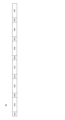
- FIGS. 5A and 5B are timing charts showing a first example of the operation executed according to the flowchart of FIG. 4.
- a production plan PL is shown.
- the production plan PL shows the setups A(a)-A(f) executed in the component mounting line LN and the mounting of components E on boards B of types K(a)-K(f).
- the setups A(a)-A(f) are the work of setting components E to be mounted on boards B of types K(a)-K(f) at the feeder set position F23 of each component mounter M in the component mounting line LN, and are executed by a user or a robot.
- setup A when there is no particular distinction between the setups A(a)-A(f), they will be referred to as setup A, and when there is no particular distinction between the types K(a)-K(f), they will be referred to as type K.
- the production plan PL in Fig. 5A shows that a setup A for setting a component E at the feeder set position F23 of each mounter M in the component mounting line LN and a component mounting for mounting the component E set in the setup A on a board B of a type K are repeated while changing the types K(a) to K(f) of the board B. Specifically, By repeating the above operations, the mounting of components E onto boards B of types K(a) to K(f) is performed. - Component E set in this setup A(a) is mounted on board B of type K(a). - Component E set in this setup A(b) is performed on board B of type K(b).
- the production program PG which indicates the conditions required for the component mounting line LN to execute this production plan PL, indicates, for multiple varieties K(a) to K(f), component position conditions that stipulate the position at which component E is set in setup A, and mounting order conditions that stipulate the order in which the components E set in setup A are mounted on board B of variety K.
- a component position condition Cp and a mounting order condition Cm that correspond to the same variety K are treated as one element condition Ce, and the production program PG is decomposed into six element conditions Ce that respectively correspond to the multiple varieties K(a) to K(f). Each element condition Ce is then assigned to a different execution server Se.
- the execution server Se1 performs a calculation to optimize (consider) the component position condition Cp that specifies the position at which component E is set in the setup A(a), and then optimize the mounting order condition Cm that specifies the order in which the component E set in the setup A(a) is to be mounted on the board B of type K(a).
- the execution server Se2 performs a calculation to optimize (consider) the component position condition Cp that specifies the position at which component E is set in the setup A(b), and then optimize the mounting order condition Cm that specifies the order in which the component E set in the setup A(b) is to be mounted on the board B of type K(b).
- the execution servers Se3 to Se6 perform a calculation to optimize the component position condition Cp and the mounting order condition Cm for types K(c) to K(f).
- the execution servers Se1 to Se6 perform their respective calculations in parallel.
- multiple operations being executed in parallel means that the periods during which each of the multiple operations is executed at least partially overlap.
- the six element conditions Ce included in the conditions defined by the production program PG are assigned to six execution servers Se1 to Se6 (computation devices, execution computation devices) (step S204). Then, each of the six execution servers Se1 to Se6 executes computations in parallel to optimize the assigned element conditions Ce (step S205).
- the conditions defined by the production program PG are broken down into six element conditions Ce, and the optimization of the six element conditions Ce is further executed in parallel by the six execution servers Se1 to Se6. As a result, it is possible to reduce the computation time required to optimize the production program PG.
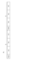
- Figures 6A and 6B are timing charts showing a second example of the operation executed according to the flowchart of Figure 4.
- Figure 6A shows a production plan PL.
- the difference between the production plan PL of Figure 5A and the production plan PL of Figure 6A is that in the production plan PL of Figure 6A, components E to be mounted on boards B of multiple types K are set in a single setup A (common setup).
- the production plan PL is This indicates that the following operations are executed in order: - execute setup A (abc) for components E to be mounted on board B of types K(a) to K(c) - mount components E set in that setup A (abc) on board B of type K(a) - mount components E set in that setup A (abc) on board B of type K(b) - mount components E set in that setup A (abc) on board B of type K(c) - execute setup A (def) for components E to be mounted on board B of types K(d) to K(f) - mount components E set in that setup A (def) on board B of type K(d) - mount components E set in that setup A (def) on board B of type K(e) - mount components E set in that setup A (def) on board B of type K(f).
- setup group G that sets part E in setup A (abc) and mounts part E set in setup A (abc) on boards B of multiple varieties K(a) to K(c)
- setup group G that sets part E in setup A (def) and mounts part E set in setup A (def) on boards B of multiple varieties K(d) to K(f) are executed in sequence.
- two setup groups G are executed in sequence.
- the production program PG which indicates the conditions required for the component mounting line LN to execute this production plan PL, indicates, for each setup A, a component position condition Cp that specifies the position at which the component E is set in setup A common to multiple boards B of multiple types K, and a mounting order condition Cm that specifies the order in which the component E set in that setup A is mounted on each of the multiple boards B of multiple types K.
- the production plan PL treats the component position condition Cp and mounting order condition Cm corresponding to one setup A as one element condition
- the production program PG is decomposed into two element conditions Ce corresponding to two setups A(abc) and A(def), respectively. Then, each element condition Ce is assigned to a different execution server Se.
- the execution server Se1 executes a calculation to optimize the element condition Ce assigned to the execution server Se1.
- Optimization (examination) of part position condition Cp that specifies the position for setting part E in setup A (abc)
- the system executes calculations such as optimizing the mounting order condition Cm which stipulates the order in which the components E set in the setup A (abc) are to be mounted on the board B of type K(a), optimizing the mounting order condition Cm which stipulates the order in which the components E set in the setup A (abc) are to be mounted on the board B of type K(b), and optimizing the mounting order condition Cm which stipulates the order in which the components E set in the setup A (abc) are to be mounted on the board B of type K(c).
- the execution server Se2 executes a calculation to optimize the element conditions Ce assigned to the execution server Se2. Optimization (examination) of part position condition Cp that specifies the position for setting part E in setup A (def)
- the controller 100 executes calculations such as optimizing the mounting order condition Cm that stipulates the order in which the components E set in the setup A (def) are to be mounted on the board B of type K (d), optimizing the mounting order condition Cm that stipulates the order in which the components E set in the setup A (def) are to be mounted on the board B of type K (e), and optimizing the mounting order condition Cm that stipulates the order in which the components E set in the setup A (def) are to be mounted on the board B of type K (f).
- the execution servers Se1 and Se2 execute their respective calculations in parallel. That is, the calculation in which the execution server Se1 optimizes the element conditions Ce assigned to the execution server Se1 and the calculation in which the execution server Se2 optimizes the element conditions Ce assigned to the execution server Se2 are executed in parallel.
- two element conditions Ce included in the conditions defined by the production program PG are assigned to two execution servers Se1, Se2 (computation devices, execution computation devices) (step S204). Then, each of the two execution servers Se1, Se2 executes computations in parallel to optimize the assigned element conditions Ce (step S205).
- the conditions defined by the production program PG are decomposed into two element conditions Ce, and the optimization of the two element conditions Ce is further executed in parallel by two computation devices. As a result, it is possible to reduce the computation time required to optimize the production program PG.
- the component mounting line LN has a plurality of feeder set positions F23 (set positions) for setting components E.
- the production program PG specifies the conditions for executing two setup groups G (FIG. 6A).
- the setup A setup work
- components E are mounted in sequence on multiple boards B of different types K.
- step S204 allocation process
- the conditions for executing the setup group G are treated as element conditions Ce, and two element conditions Ce corresponding to the two setup groups G are assigned to two execution servers Se1 and Se2 (FIG. 6B).
- the conditions specified in the production program PG are decomposed into two element conditions Ce corresponding to the two setup groups G (step S204). Then, the optimization of the two element conditions Ce is performed in parallel by the two execution servers Se1 and Se2 (step S205). As a result, it is possible to reduce the calculation time required to optimize the production program PG.
- one setup group G may be further decomposed, and one component position condition Cp and multiple mounting order conditions Cm may each be set as an element condition Ce.
- Figure 7 is a flowchart showing a second example of control executed by an optimization system to optimize a production program
- Figure 8 is a first example of a timing chart that shows the content of the calculation executed according to the flowchart of Figure 7. Note that Figure 8 corresponds to an example in which, in a setup group G, components E are mounted in order on two boards B of type K after one setup A.
- step S301 the management server Sm assigns the optimization (study) of the part position condition Cp, which specifies the position where part E is to be set in setup A, to one execution server Se1. Then, in step S302, the management server Sm causes the execution server Se1 to execute the optimization of the part position condition Cp (step S302). As a result, as shown in FIG. 8, the execution server Se1 optimizes the part position condition Cp from time t0 to t2.
- the management server Sm assigns the optimization of multiple (2) mounting order conditions Cm, each of which specifies the order in which components E set according to the optimized component position conditions Cp are to be mounted on multiple (2) boards B of type K, to multiple (2) different execution servers Se1 and Se2 (step S303). Then, in step S304, the management server Sm causes the two execution servers Se1 and Se2 to optimize the mounting order conditions Cm assigned to each of them (step S304). As a result, as shown in FIG.
- the execution server Se1 optimizes the mounting order conditions Cm assigned to the execution server Se1 from time t2 to t5
- the execution server Se2 optimizes the mounting order conditions Cm assigned to the execution server Se2 from time t2 to t6.
- the two execution servers Se1 and Se2 perform optimization in parallel of the mounting order conditions Cm for two different boards B of different types K on which components E are mounted in the same setup group G.
- the management server Sm assigns the determination of whether or not steps S301 to S304 need to be re-executed to the execution server Se2 (step S306). Then, the execution server Se2 executes the determination of whether or not it needs to be assigned (step S307). That is, as described above, in the component mounting line LN, one board B is sequentially carried into multiple component mounters M, and each of the multiple component mounters M mounts a component E on the board B in sequence.
- step S307 if there are two component mounters M among the multiple component mounters M whose difference in the time (takt time) required for the component mounters M to complete the mounting of the component E in their charge is equal to or greater than a predetermined time, it is determined that steps S301 to S304 need to be re-executed ("YES" in step S307). On the other hand, if the difference in takt time between any two of the multiple component mounters M is less than a predetermined time, it is determined that there is no need to re-execute steps S301 to S304 ("NO" in step S307).
- the execution server Se2 judges whether re-execution is necessary between times t6 and t7, and judges that re-execution is necessary ("YES" in step S307). Therefore, the management server Sm returns to step S301 and assigns one execution server Se2 to optimize (consider) the component position condition Cp that specifies the position where component E is set in setup A. In step S302, the management server Sm causes the execution server Se2 to optimize the component position condition Cp (step S302). At this time, the execution server Se2 determines the component position condition Cp so that the difference in takt time is shortened among the multiple component mounters M.
- execution server Se2 determines that component E to be mounted on board B should be moved from the component mounter M with the longest takt time to the component mounter M with the shortest takt time (optimization of component position condition Cp).
- execution server Se2 performs optimization of part position condition Cp from time t7 to t9.
- the management server Sm assigns the optimization of the multiple (2) mounting order conditions Cm, each of which specifies the order in which the components E set in the setup A are to be mounted on the multiple (2) boards B of type K, to the multiple (2) different execution servers Se2 and Se3 (step S303). Then, in step S304, the management server Sm causes the two execution servers Se2 and Se3 to optimize the mounting order conditions Cm assigned to them (step S304). As a result, as shown in FIG. 8, the execution server Se2 optimizes the mounting order conditions Cm assigned to the execution server Se2 from time t9 to t13, and the execution server Se3 optimizes the mounting order conditions Cm assigned to the execution server Se3 from time t10 to t13. In this way, the two execution servers Se2 and Se3 perform in parallel optimization of the mounting order conditions Cm corresponding to two different boards B of different types K on which components E are mounted in the same setup group G.
- the management server Sm assigns the determination of whether or not steps S301 to S304 need to be re-executed to the execution server Se2 (step S306).
- the execution server Se2 then executes the assigned determination of whether or not re-execution is necessary (step S307).
- the management server Sm determines whether or not re-execution is necessary at times t11 to t12 and determines that re-execution is not necessary ("NO" in step S306). Therefore, the management server Sm ends the flowchart of FIG. 7.
- the management server Sm changes the execution server Se to which the optimization of the same element condition Ce is assigned for different loops. For example, the management server Sm assigns the optimization of the component position condition Cp to the execution server Se1 in the first loop, but assigns it to the execution server Se2 in the second loop. In addition, the management server Sm assigns the optimization of the mounting order condition Cm for the same board B of type K to the execution server Se1 in the first loop, but assigns it to the execution server Se2 in the second loop. This makes it possible to dynamically change the execution server Se to which the optimization of the element condition Ce is assigned depending on the operating status of the execution server Se.
- two element conditions Ce that can perform calculations in parallel to optimize each of them are assigned to two execution servers Se (calculation device, execution calculation device) (step S303). Then, each of the two execution servers Se executes calculations in parallel to optimize the assigned mounting order conditions Cm (step S304).
- the conditions defined by the production program PG are decomposed into three element conditions Ce (part position condition Cp and two mounting order conditions Cm), and the optimization of two of the three element conditions Ce (mounting order conditions Cm) is executed in parallel by two execution servers Se.
- Ce part position condition Cp and two mounting order conditions Cm
- a calculation for optimizing one component position condition Cp that is different from the two mounting order conditions Cm is executed at a timing (step S302) different from that of step S304 (parallel optimization process).
- a calculation for optimizing one component position condition Cp can be executed at an appropriate timing.
- the component mounting line LN also has a number of feeder set positions F23 for setting components E.
- the production program PG specifies the conditions for executing the setup group G, and in the setup group G, after the execution of setup A (setup work) for setting components E at the feeder set positions F23, the components E set at the feeder set positions F23 are mounted in order on two boards B of type K.
- the mounting order condition Cm indicating the order in which components E are mounted on one board B of type K is treated as an element condition Ce
- two element conditions Ce mounting order condition Cm
- the conditions defined in the production program PG are decomposed into three element conditions Ce (component position condition Cp and two mounting order conditions Cm), including two element conditions Ce (mounting order condition Cm) corresponding to the two boards B of type K. Then, the optimization of the two element conditions Ce (component position condition Cp) is executed in parallel by the two execution servers Se (step S304). As a result, it is possible to reduce the calculation time required to optimize the production program PG.
- step S302 for optimizing part E to be set at feeder set position F23 in setup A (setup work) is executed before step S303 (allocation process). Then, the process waits for the completion of the optimization of the two element conditions Ce (mounting order conditions Cm) executed by the two execution servers Se (step S305). When the optimization of the two element conditions Ce (mounting order conditions Cm) is completed (step S305: "YES"), a determination is made based on the results of the optimization of the two element conditions Ce (step S307) as to whether or not step S302 (part position optimization process) needs to be re-executed.
- step S302 When it is determined that step S302 needs to be re-executed (step S307: "YES"), step S302 (part position optimization process), step S303 (allocation process), and step S304 (parallel optimization process) are executed.
- step S302 part position optimization process
- step S303 allocation process
- step S304 parallel optimization process
- Figures 9A and 9B are timing charts showing the operation of mounting components E in order on three types K(a) to K(c) on a component mounting line LN.
- the execution server Se which determines whether or not re-execution of step S307 is required, performs this semi-determination by predicting each timing shown in both figures based on the results of optimizing the component position conditions Cp and the mounting order conditions Cm. For example, such a prediction can be made by simulating the operation of mounting components E in the order indicated by the mounting order conditions Cm while placing them in accordance with the component position conditions Cp.
- a difference ⁇ occurs in the time (takt time) required to mount component E on one board B of type K(c) between component mounters M2 and M3. Because this difference ⁇ is equal to or greater than a predetermined time, it is determined that step S302 needs to be re-executed ("YES" in step S307). In addition, in the re-executed step S302, the execution server Se decides to move component E, which is to be mounted on board B of type K(c), from feeder set position F23 of component mounter M2 to feeder set position F23 of component mounter M3 (optimization of component position condition Cp).
- a difference ⁇ occurs in the time (takt time) required to mount component E on one board B of type K(a) between component mounters M1 and M3. Because this difference ⁇ is equal to or greater than a predetermined time, it is determined that step S302 needs to be re-executed ("YES" in step S307). In addition, in the re-executed step S302, the execution server Se determines that component E to be mounted on board B of type K(a) should be moved from feeder set position F23 of component mounter M1 to feeder set position F23 of component mounter M3 (optimization of component position condition Cp).
- FIG. 10 is a second example of a timing chart that shows the content of the calculations executed according to the flowchart of FIG. 7.
- step S301 the management server Sm assigns the optimization (study) of the part position condition Cp, which specifies the position where part E is to be set in setup A, to one execution server Se1. Then, in step S302, the management server Sm causes the execution server Se1 to execute the optimization of the part position condition Cp (step S302). As a result, as shown in FIG. 10, the execution server Se1 optimizes the part position condition Cp from time t0 to t2.
- the management server Sm assigns optimization of multiple (three) mounting order conditions Cm indicating the order in which each of the multiple (three) component mounters M1, M2, M3 mounts components E on the board B to multiple (three) different execution servers Se1, Se2, Se3, assuming that components E have been set according to the optimized component position conditions Cp (step S303). Then, in step S304, the management server Sm causes the three execution servers Se1, Se2, Se3 to optimize the mounting order conditions Cm assigned to them (step S304). As a result, as shown in FIG.
- the execution server Se1 optimizes the mounting order condition Cm for the mounter M1 assigned to the execution server Se1 from time t2 to t5
- the execution server Se2 optimizes the mounting order condition Cm for the mounter M2 assigned to the execution server Se2 from time t2 to t7
- the execution server Se3 optimizes the mounting order condition Cm for the mounter M3 assigned to the execution server Se3 from time t2 to t4.
- the three execution servers Se1, Se2, and Se3 optimize the mounting order condition Cm for each of the three different mounters M1, M2, and M3 in parallel.
- the management server Sm assigns the determination of whether or not steps S301 to S304 need to be re-executed to the execution server Se2 (step S306). Then, the execution server Se2 executes the assigned determination of whether or not it needs to be re-executed (step S307).
- the method of determination here is as described above.
- the execution server Se2 determines whether re-execution is necessary from time t7 to t8, and determines that re-execution is necessary ("YES" in step S307). Therefore, the management server Sm returns to step S301 and assigns the optimization (review) of the part position condition Cp that specifies the position where part E is to be set to one execution server Se2. In step S302, the management server Sm causes the execution server Se2 to optimize the part position condition Cp (step S302). The optimization method here is as described above. In the example of FIG. 10, the execution server Se2 optimizes the part position condition Cp from time t8 to t10.
- the management server Sm assigns optimization of multiple (three) mounting order conditions Cm indicating the order in which each of the multiple (three) component mounters M1, M2, M3 mounts components E on the board B to multiple (three) different execution servers Se1, Se2, Se4, assuming that components E have been set according to the optimized component position condition Cp (step S303). Then, in step S304, the management server Sm causes the three execution servers Se1, Se2, Se4 to optimize the mounting order conditions Cm assigned to them (step S304). As a result, as shown in FIG.
- the execution server Se1 optimizes the mounting order condition Cm for the mounter M1 assigned to the execution server Se1 from time t10 to t14
- the execution server Se2 optimizes the mounting order condition Cm for the mounter M2 assigned to the execution server Se2 from time t10 to t13
- the execution server Se4 optimizes the mounting order condition Cm for the mounter M3 assigned to the execution server Se4 from time t10 to t13.
- the three execution servers Se1, Se2, and Se4 optimize the mounting order condition Cm for the three mutually different mounters M1, M2, and M3 in parallel.
- the management server Sm assigns the determination of whether or not steps S301 to S304 need to be re-executed to the execution server Se1 (step S306).
- the execution server Se1 then executes the assigned determination of whether or not re-execution is necessary (step S307).
- the management server Sm ends the flowchart of FIG. 7.
- the conditions defined by the production program PG are decomposed into four element conditions Ce (component position condition Cp and three mounting order conditions Cm), and the optimization of three of the four element conditions Ce (mounting order conditions Cm) is executed in parallel by the three execution servers Se.
- Ce component position condition
- Cm mounting order conditions
- a calculation for optimizing one element condition Ce (component position condition Cp) that is different from the three element conditions Ce (mounting order condition Cm) is executed at a timing (step S302) different from that of step S304 (parallel optimization process).
- a calculation for optimizing one element condition Ce (mounting order condition Cm) can be executed at an appropriate timing.
- the component mounting line LN also includes three component mounters M arranged in series, and the production program PG specifies conditions for transporting the board B to the three component mounters M in order and for each of the three component mounters M to mount a component E on the board B.
- the mounting order condition Cm indicating the order in which one component mounter M mounts a component E on the board B is treated as an element condition Ce
- three element conditions Ce mounting order condition Cm corresponding to each of the three component mounters M are assigned to three execution servers Se.
- the conditions specified in the production program PG are decomposed into four element conditions Ce (component position condition Cp and three mounting order conditions Cm) including three element conditions Ce (mounting order condition Cm) corresponding to each of the three component mounters M. Then, the optimization of the three element conditions Ce (mounting order condition Cm) is executed in parallel by the three execution servers Se (step S304). As a result, it is possible to reduce the calculation time required to optimize the production program PG.
- step S302 for optimizing the components E to be set on the three component mounters M is executed before step S303 (allocation process). Then, the process waits for the completion of the optimization of the three element conditions Ce (mounting order conditions Cm) executed by the three execution servers Se (step S305). When the optimization of the three element conditions Ce (mounting order conditions Cm) is completed, a determination is made as to whether or not step S302 (component position optimization process) needs to be re-executed based on the results of the optimization of the three element conditions Ce (mounting order conditions Cm) (step S307).
- step S302 component position optimization process
- step S303 allocation process
- step S304 parallel optimization process
- step S204 or S303 corresponds to an example of the "allocation process” of the present invention
- step S205 or step S304 corresponds to an example of the "parallel optimization process” of the present invention
- step S302 corresponds to an example of the “component position optimization process” of the present invention
- the optimization system SY functions as the "optimization system” of the present invention
- the management server Sm functions as the "production program acquisition unit,” “allocation process execution unit,” “parallel optimization process execution unit,” “board production program optimization device” and “management calculation device” of the present invention
- the execution server Se functions as the “calculation device” and “execution calculation device” of the present invention
- the execution server Se functions as the "cloud computing device” of the present invention.
- the local server Sl corresponds to an example of a "terminal device" of the present invention
- the production program PG corresponds to an example of a "production program” or "optimization target data” of the present invention
- the element condition Ce corresponds to an example of an "element condition” of the present invention
- the component mounting line LN corresponds to an example of a "component mounting line” of the present invention
- the component mounter M corresponds to an example of a “component mounter” of the present invention
- the feeder set position F23 corresponds to an example of a "set position” of the present invention
- the board B corresponds to an example of a "board” of the present invention
- the component E corresponds to an example of a "component” of the present invention
- the setup A corresponds to an example of a "setup work” of the present invention
- the setup group G corresponds to an example of a "setup group” of the present invention.
- the management server Sm and execution server Se do not need to be installed on the cloud, but may be installed on the user's premises PR and connected to the local server SL via a local area network NW.
- the number of component mounters M that make up the component mounting line LN may be changed as appropriate.
- the number of types K of boards B to be mounted in the setup group G may be changed as appropriate.
- the example shown in the timing chart of FIG. 10 can be modified as appropriate.
- the optimization of three (N) mounting order conditions Cm indicating the order in which each of three (N) mounters M1, M2, and M3 mounts components E on the board B may be assigned to two (Q) execution servers Se1 and Se2.
- the optimization of two mounting order conditions Cm indicating the order in which each of two mounters M1 and M2 mounts components E on the board B may be assigned to the execution server Se1
- the optimization of one mounting order condition Cm indicating the order in which each of one mounters M3 mounts components E on the board B may be assigned to the execution server Se2.
- the optimization of the two mounting order conditions Cm by the execution server Se1 and the optimization of the one mounting order condition Cm by the execution server Se2 are executed in parallel.
- the execution server Se1 serially (i.e., sequentially) executes optimization of the mounting order condition Cm indicating the order in which the mounter M1 mounts the components E on the board B, and optimization of the mounting order condition Cm indicating the order in which the mounter M2 mounts the components E on the board B.
- This method is suitable, for example, when there is a shortage of execution servers Se that can be used for optimization calculations in the optimization system SY.
- steps S204 to S206 in FIG. 4 are executed according to the number of production programs PG included in the optimization execution list (optimization target data). Therefore, when multiple production programs PG are included in the optimization list, the optimization of these multiple production programs PG will be executed in parallel by different execution servers Se. In this case, the optimization of each production program PG may be executed in parallel without breaking down each production program PG into element conditions.
- FIG. 11 shows an example of a timing chart for optimizing multiple production programs in parallel.
- multiple production programs PG1, PG2, PG3 are assigned to multiple execution servers Se1, Se2, Se3, respectively.
- the multiple execution servers Se1, Se2, Se3 then execute the optimization of the multiple production programs PG1, PG2, PG3 assigned to them in parallel.
- the optimization of production program PG1 by execution server Se1 the optimization of production program PG2 by execution server Se2
- the optimization of production program PG3 by execution server Se3 are executed in parallel.
- N (3) different production programs PG1, PG2, PG3 included in the optimization execution list (optimization target data) are assigned to Q (3) execution servers Se1, Se2, Se3 (assignment process).
- the Q (3) execution servers Se1, Se2, Se3 execute in parallel calculations to optimize the assigned production programs PG1, PG2, PG3 (parallel optimization process).
- multiple computers are not used to optimize the same production program PG, but are used to optimize the different production programs PG1, PG2, PG3.
- the three production programs PG1, PG2, PG3 may be assigned to two execution servers Se1, Se2, Se3.
- the optimization of the production programs PG1, PG2 by the execution server Se1 and the optimization of the production program PG3 by the execution server Se1 are executed in parallel. This method is suitable, for example, when there is a shortage of execution servers Se that can be used for optimization calculations in the optimization system SY.
- Sm Management server Se: Execution server Se
- Sl Local server PG: Production program (optimization target data) Ce...Element condition LN...Component mounting line M...Component mounting machine F23...Feeder set position B...Board E...Component A...Setup G...Setup group
Landscapes
- Engineering & Computer Science (AREA)
- Software Systems (AREA)
- Theoretical Computer Science (AREA)
- Physics & Mathematics (AREA)
- General Engineering & Computer Science (AREA)
- General Physics & Mathematics (AREA)
- Mathematical Physics (AREA)
- Supply And Installment Of Electrical Components (AREA)
- General Factory Administration (AREA)
Abstract
Description
・部品位置条件…各部品実装機Mにおいて各種の部品Eがセットされる位置(具体的にはフィーダーセット位置F23)を規定する条件
・実装順序条件…基板Bの各実装点に実装する部品Eと各実装点に部品Eを実装する順序を規定する条件
を含む。そして、生産プログラムPGの最適化では、生産計画の実行完了に要する時間の短縮を図るために、少なくとも部品位置条件および実装順序条件が最適化される。
・品種K(a)の基板Bに実装される部品Eの段取りA(a)を実行
・当該段取りA(a)でセットされた部品Eを品種K(a)の基板Bに実装
・品種K(b)の基板Bに実装される部品Eの段取りA(b)を実行
・当該段取りA(b)でセットされた部品Eを品種K(b)の基板Bに実装
といった動作を繰り返すことで、品種K(a)~K(f)の基板Bへの部品Eの実装が実行される。
・品種K(a)~K(c)の基板Bに実装される部品Eの段取りA(abc)を実行
・当該段取りA(abc)でセットされた部品Eを品種K(a)の基板Bに実装
・当該段取りA(abc)でセットされた部品Eを品種K(b)の基板Bに実装
・当該段取りA(abc)でセットされた部品Eを品種K(c)の基板Bに実装
・品種K(d)~K(f)の基板Bに実装される部品Eの段取りA(def)を実行
・当該段取りA(def)でセットされた部品Eを品種K(d)の基板Bに実装
・当該段取りA(def)でセットされた部品Eを品種K(e)の基板Bに実装
・当該段取りA(def)でセットされた部品Eを品種K(f)の基板Bに実装
といった動作を順番に実行することを示す。
・段取りA(abc)で部品Eをセットする位置を規定する部品位置条件Cpの最適化(検討)
・当該段取りA(abc)でセットされた部品Eを品種K(a)の基板Bに実装する順序を規定する実装順序条件Cmの最適化
・当該段取りA(abc)でセットされた部品Eを品種K(b)の基板Bに実装する順序を規定する実装順序条件Cmの最適化
・当該段取りA(abc)でセットされた部品Eを品種K(c)の基板Bに実装する順序を規定する実装順序条件Cmの最適化
を順に行うといった演算を実行する。
・段取りA(def)で部品Eをセットする位置を規定する部品位置条件Cpの最適化(検討)
・当該段取りA(def)でセットされた部品Eを品種K(d)の基板Bに実装する順序を規定する実装順序条件Cmの最適化
・当該段取りA(def)でセットされた部品Eを品種K(e)の基板Bに実装する順序を規定する実装順序条件Cmの最適化
・当該段取りA(def)でセットされた部品Eを品種K(f)の基板Bに実装する順序を規定する実装順序条件Cmの最適化
を順に行うといった演算を実行する。
S205、S304…ステップ(並列最適化処理)
S302…ステップ(部品位置最適化処理)
SY…最適化システム
Sm…管理サーバー
Se…実行サーバーSe
Sl…ローカルサーバー
PG…生産プログラム(最適化対象データ)
Ce…要素条件
LN…部品実装ライン
M…部品実装機
F23…フィーダーセット位置
B…基板
E…部品
A…段取り
G…段取りグループ
Claims (13)
- 部品実装ラインで基板に部品を実装するための条件を規定する生産プログラムを含む最適化対象データを取得する工程と、
前記最適化対象データに含まれる互いに異なるN個(Nは2以上の整数)の要素データを、Q個(Qは2以上であってN以下の整数)の演算装置に割り当てる割り当て処理を実行する工程と、
前記Q個の演算装置が前記割り当て処理でそれぞれに割り当てられた前記要素データを最適化する演算を並列して実行する並列最適化処理を実行する工程と
を備える基板生産プログラムの最適化方法。 - 前記割り当て処理では、前記生産プログラムにより規定される条件に含まれるM個(MはN以上の整数)の要素条件のうち、それぞれの要素条件を最適化する演算を並列して実行可能なN個の要素条件を、前記N個の要素データとしてQ個の演算装置に割り当て、
前記並列最適化処理では、前記Q個の演算装置が前記割り当て処理でそれぞれに割り当てられた前記要素条件を最適化する演算を並列して実行する請求項1に記載の基板生産プログラムの最適化方法。 - NがM未満である場合には、前記M個の要素条件のうち、前記N個の要素条件とは異なる(M-N)個の要素条件を最適化する演算を、前記並列最適化処理とは異なるタイミングで実行する請求項2に記載の基板生産プログラムの最適化方法。
- 前記部品実装ラインは、それぞれ部品をセットするための複数のセット位置を有し、
前記生産プログラムは、N個の段取りグループを実行するための条件を規定し、
前記N個の段取りグループのそれぞれでは、前記セット位置に部品をセットする段取り作業の実行後に、複数の種類の基板に順番に部品が実装され、
前記割り当て処理では、前記段取りグループを実行するための条件を前記要素条件として扱って、前記N個の段取りグループにそれぞれ対応する前記N個の要素条件を前記Q個の演算装置に割り当てる請求項2または3に記載の基板生産プログラムの最適化方法。 - 前記部品実装ラインは、それぞれ部品をセットするための複数のセット位置を有し、
前記生産プログラムは、段取りグループを実行するための条件を規定し、
前記段取りグループでは、前記セット位置に部品をセットする段取り作業の実行後に、前記セット位置にセットされた部品がN種類の基板に順番に実装され、
前記割り当て処理では、1種類の基板に対して部品を実装する順序を示す条件を前記要素条件として扱って、前記N種類の基板にそれぞれ対応する前記N個の要素条件を前記Q個の演算装置に割り当てる請求項2または3に記載の基板生産プログラムの最適化方法。 - 前記段取り作業で前記セット位置にセットする部品を最適化する部品位置最適化処理を、前記割り当て処理の前に実行する工程と、
前記Q個の演算装置により実行される前記N個の要素条件の最適化が完了するのを待機する工程と、
前記N個の要素条件の最適化が完了すると、前記N個の要素条件の最適化の結果に基づき、前記部品位置最適化処理の再実行の要否を判定する工程と、
前記部品位置最適化処理の再実行が必要と判定されると、前記部品位置最適化処理、前記割り当て処理および前記並列最適化処理を実行する請求項5に記載の基板生産プログラムの最適化方法。 - 前記部品実装ラインは、直列に配列されたN個の部品実装機を備え、
前記生産プログラムは、前記N個の部品実装機に順番に基板を搬送して前記N個の部品実装機のそれぞれに基板に部品を実装させるための条件を規定し、
前記割り当て処理では、1個の部品実装機が基板へ部品を実装する順序を示す条件を前記要素条件として扱って、前記N個の部品実装機にそれぞれ対応する前記N個の要素条件を前記Q個の演算装置に割り当てる請求項2または3に記載の基板生産プログラムの最適化方法。 - 前記N個の部品実装機にセットする部品を最適化する部品位置最適化処理を、前記割り当て処理の前に実行する工程と、
前記Q個の演算装置により実行される前記N個の要素条件の最適化が完了するのを待機する工程と、
前記N個の要素条件の最適化が完了すると、前記N個の要素条件の最適化の結果に基づき、前記部品位置最適化処理の再実行の要否を判定する工程と、
前記部品位置最適化処理の再実行が必要と判定されると、前記部品位置最適化処理、前記割り当て処理および前記並列最適化処理を実行する請求項7に記載の基板生産プログラムの最適化方法。 - 所定の端末装置から送信された前記最適化対象データを受信することで、前記生産プログラムを取得し、
前記Q個の演算装置は、Q個のクラウドサーバーである請求項1ないし8のいずれか一項に記載の基板生産プログラムの最適化方法。 - 所定の端末装置から送信された前記最適化対象データを受信することで、前記生産プログラムを取得し、
前記Q個の演算装置は、前記端末装置とローカルエリアネットワークで接続されたQ個のサーバーである請求項1ないし8のいずれか一項に記載の基板生産プログラムの最適化方法。 - 前記割り当て処理では、前記最適化対象データに含まれる互いに異なるN個の生産プログラムを、前記N個の要素データとしてQ個の演算装置に割り当て、
前記並列最適化処理では、前記Q個の演算装置が前記割り当て処理でそれぞれに割り当てられた前記生産プログラムを最適化する演算を並列して実行する請求項1に記載の基板生産プログラムの最適化方法。 - 部品実装ラインで基板に部品を実装するための条件を規定する生産プログラムを含む最適化対象データを取得する生産プログラム取得部と、
前記最適化対象データに含まれる互いに異なるN個(Nは2以上の整数)の要素データを、Q個(Qは2以上であってN以下の整数)の演算装置に割り当てる割り当て処理実行部と、
前記Q個の演算装置のそれぞれに、割り当てられた前記要素データを最適化する演算を並列して実行させる並列最適化処理実行部と
を備える基板生産プログラムの最適化装置。 - 管理演算装置と、
複数の実行演算装置と
を備え、
前記管理演算装置は、
部品実装ラインで基板に部品を実装するための条件を規定する生産プログラムを含む最適化対象データを取得する生産プログラム取得部と、
前記最適化対象データに含まれる互いに異なるN個(Nは2以上の整数)の要素データを、前記複数の実行演算装置のうちQ個(Qは2以上であってN以下の整数)の実行演算装置に割り当てる割り当て処理実行部と
を有し、
前記Q個の実行演算装置のそれぞれは、割り当てられた前記要素データを最適化する演算を並列して実行する基板生産プログラムの最適化システム。
Priority Applications (4)
| Application Number | Priority Date | Filing Date | Title |
|---|---|---|---|
| CN202380098498.7A CN121175662A (zh) | 2023-06-07 | 2023-06-07 | 基板生产程序的优化方法、优化装置以及优化系统 |
| DE112023006467.9T DE112023006467T5 (de) | 2023-06-07 | 2023-06-07 | Optimierungsverfahren, Optimierungsvorrichtung und Optimierungssystem für ein Leiterplatten-Produktionsprogramm |
| JP2025525528A JPWO2024252562A1 (ja) | 2023-06-07 | 2023-06-07 | |
| PCT/JP2023/021172 WO2024252562A1 (ja) | 2023-06-07 | 2023-06-07 | 基板生産プログラムの最適化方法、最適化装置および最適化システム |
Applications Claiming Priority (1)
| Application Number | Priority Date | Filing Date | Title |
|---|---|---|---|
| PCT/JP2023/021172 WO2024252562A1 (ja) | 2023-06-07 | 2023-06-07 | 基板生産プログラムの最適化方法、最適化装置および最適化システム |
Publications (1)
| Publication Number | Publication Date |
|---|---|
| WO2024252562A1 true WO2024252562A1 (ja) | 2024-12-12 |
Family
ID=93795409
Family Applications (1)
| Application Number | Title | Priority Date | Filing Date |
|---|---|---|---|
| PCT/JP2023/021172 Ceased WO2024252562A1 (ja) | 2023-06-07 | 2023-06-07 | 基板生産プログラムの最適化方法、最適化装置および最適化システム |
Country Status (4)
| Country | Link |
|---|---|
| JP (1) | JPWO2024252562A1 (ja) |
| CN (1) | CN121175662A (ja) |
| DE (1) | DE112023006467T5 (ja) |
| WO (1) | WO2024252562A1 (ja) |
Citations (3)
| Publication number | Priority date | Publication date | Assignee | Title |
|---|---|---|---|---|
| JPS63221454A (ja) * | 1987-03-11 | 1988-09-14 | Fujitsu Ltd | 並列計算機制御方式 |
| JP2013061779A (ja) * | 2011-09-13 | 2013-04-04 | Toyota Motor Corp | パラメータ適合方法及びパラメータ適合システム |
| JP6025161B2 (ja) * | 2011-12-26 | 2016-11-16 | ハンファテクウィン株式会社Hanwha Techwin Co.,Ltd. | 電子部品実装の最適化方法及び最適化プログラム |
-
2023
- 2023-06-07 JP JP2025525528A patent/JPWO2024252562A1/ja active Pending
- 2023-06-07 WO PCT/JP2023/021172 patent/WO2024252562A1/ja not_active Ceased
- 2023-06-07 DE DE112023006467.9T patent/DE112023006467T5/de active Pending
- 2023-06-07 CN CN202380098498.7A patent/CN121175662A/zh active Pending
Patent Citations (3)
| Publication number | Priority date | Publication date | Assignee | Title |
|---|---|---|---|---|
| JPS63221454A (ja) * | 1987-03-11 | 1988-09-14 | Fujitsu Ltd | 並列計算機制御方式 |
| JP2013061779A (ja) * | 2011-09-13 | 2013-04-04 | Toyota Motor Corp | パラメータ適合方法及びパラメータ適合システム |
| JP6025161B2 (ja) * | 2011-12-26 | 2016-11-16 | ハンファテクウィン株式会社Hanwha Techwin Co.,Ltd. | 電子部品実装の最適化方法及び最適化プログラム |
Also Published As
| Publication number | Publication date |
|---|---|
| DE112023006467T5 (de) | 2026-04-02 |
| JPWO2024252562A1 (ja) | 2024-12-12 |
| CN121175662A (zh) | 2025-12-19 |
Similar Documents
| Publication | Publication Date | Title |
|---|---|---|
| JP5535032B2 (ja) | 部品装着システム、部品装着設定装置、部品装着設定プログラム、及び部品装着方法 | |
| JP5480776B2 (ja) | 実装モード決定方法及び部品実装システム | |
| CN105704996A (zh) | 管理装置以及部件补充作业的管理方法 | |
| JP4996634B2 (ja) | 実装条件決定方法および実装条件決定装置 | |
| JP6395708B2 (ja) | 複数の生産ラインを有する電子部品装着システムの管理方法及び管理装置 | |
| CN113955362B (zh) | 立体分拣控制方法、立体分拣机器人和相关设备 | |
| Öztürk et al. | Balancing and scheduling of flexible mixed model assembly lines with parallel stations | |
| JP7769961B2 (ja) | 生産計画作成方法および生産計画作成装置 | |
| CN110494812A (zh) | 生产计划生成装置、生产计划生成程序及生产计划生成方法 | |
| CN114585982A (zh) | 配置辅助方法、学习完毕模型的生成方法、程序、配置辅助系统以及作业系统 | |
| JP4302422B2 (ja) | 部品実装方法及びシステム | |
| JP5038970B2 (ja) | 実装条件決定方法、実装条件決定装置、部品実装方法、部品実装機およびプログラム | |
| JP6820897B2 (ja) | 設置機用セットアップキットの準備方法 | |
| CN121175662A (zh) | 基板生产程序的优化方法、优化装置以及优化系统 | |
| JP4887328B2 (ja) | 実装条件決定方法 | |
| JP2004146641A (ja) | 電子部品実装ラインにおける設備構成最適化シミュレーション方法 | |
| JP2009224766A (ja) | 実装条件決定方法、実装条件決定装置、部品実装方法、部品実装機及びプログラム | |
| US11076521B2 (en) | Production plan creation system and production plan creation method | |
| JP5077284B2 (ja) | 電子部品実装装置およびデータダウンロード方法 | |
| JP7186572B2 (ja) | 部品実装システム、実装プログラム最適化装置、部品実装方法 | |
| JP5802602B2 (ja) | 部品供給機の取付個数決定装置、部品供給機の取付個数決定方法、記録媒体、部品実装機、部品実装システム | |
| CN115146941B (zh) | 生产场景中agv小车的调度方法和装置 | |
| JP6644844B2 (ja) | 複数の生産ラインを有する電子部品装着システムの管理方法及び割付装置 | |
| KR102440645B1 (ko) | 사이클 단위의 부분 최적화 방법 | |
| CN103279339A (zh) | 一种代码上线系统及方法 |
Legal Events
| Date | Code | Title | Description |
|---|---|---|---|
| 121 | Ep: the epo has been informed by wipo that ep was designated in this application |
Ref document number: 23940008 Country of ref document: EP Kind code of ref document: A1 |
|
| ENP | Entry into the national phase |
Ref document number: 2025525528 Country of ref document: JP Kind code of ref document: A |
|
| WWE | Wipo information: entry into national phase |
Ref document number: 2025525528 Country of ref document: JP |
|
| WWE | Wipo information: entry into national phase |
Ref document number: 112023006467 Country of ref document: DE |
|
| WWP | Wipo information: published in national office |
Ref document number: 112023006467 Country of ref document: DE |