WO2024252456A1 - 誘電分光センサ及び複素誘電率の測定方法 - Google Patents
誘電分光センサ及び複素誘電率の測定方法 Download PDFInfo
- Publication number
- WO2024252456A1 WO2024252456A1 PCT/JP2023/020787 JP2023020787W WO2024252456A1 WO 2024252456 A1 WO2024252456 A1 WO 2024252456A1 JP 2023020787 W JP2023020787 W JP 2023020787W WO 2024252456 A1 WO2024252456 A1 WO 2024252456A1
- Authority
- WO
- WIPO (PCT)
- Prior art keywords
- dielectric
- layer
- measurement
- spectroscopy sensor
- sensor
- Prior art date
- Legal status (The legal status is an assumption and is not a legal conclusion. Google has not performed a legal analysis and makes no representation as to the accuracy of the status listed.)
- Ceased
Links
Images



Classifications
-
- A—HUMAN NECESSITIES
- A61—MEDICAL OR VETERINARY SCIENCE; HYGIENE
- A61B—DIAGNOSIS; SURGERY; IDENTIFICATION
- A61B5/00—Measuring for diagnostic purposes; Identification of persons
-
- G—PHYSICS
- G01—MEASURING; TESTING
- G01N—INVESTIGATING OR ANALYSING MATERIALS BY DETERMINING THEIR CHEMICAL OR PHYSICAL PROPERTIES
- G01N22/00—Investigating or analysing materials by the use of microwaves or radio waves, i.e. electromagnetic waves with a wavelength of one millimetre or more
Definitions
- the present invention relates to a technique for measuring the complex dielectric constant of a liquid, a semi-solid material, or a living body.
- Non-Patent Document 1 there is a method using a resonant structure as shown in Non-Patent Document 1.
- a measurement sample is brought into contact with a device with a high Q value, such as an antenna or resonator, and the frequency characteristics around the resonant frequency are measured. Since the resonant frequency is determined by the complex dielectric constant around the device, the component concentration is estimated from the resonant frequency shift by predicting in advance the correlation between the resonant frequency shift and the component concentration.
- dielectric spectroscopy As another method using microwave-millimeter wave electromagnetic waves, dielectric spectroscopy, shown in Patent Document 1, has been proposed.
- dielectric spectroscopy electromagnetic waves are irradiated into the skin, and the electromagnetic waves are absorbed according to the interaction between the blood component to be measured, for example, glucose molecules and water, and the amplitude and phase of the electromagnetic waves are observed.
- a dielectric relaxation spectrum is calculated from the amplitude and phase of the observed electromagnetic waves at the frequency.
- the dielectric relaxation spectrum is generally expressed as a linear combination of relaxation curves based on the Cole-Cole equation, and the complex dielectric constant is calculated.
- the complex dielectric constant is correlated with the amount of blood components, such as glucose or cholesterol, contained in the blood, and is measured as an electrical signal (amplitude and phase) corresponding to the change.
- a calibration model is constructed by measuring the correlation between the change in complex dielectric constant and the component concentration in advance, and the component concentration is calibrated from the change in the measured dielectric relaxation spectrum.
- Non-Patent Documents 2 and 3 and Patent Document 2 can use easily available samples such as water to calibrate the measuring device, and can measure the dielectric constant of the sample to be measured by contacting the end of the probe without requiring special processing of the material, making it suitable for measuring samples in which the concentration of components contained in a living organism is to be evaluated.
- Non-Patent Document 6 discloses that the area measured by the sensor in the living body is considered to have a structure consisting of four layers: the stratum corneum, epidermis layer, dermis layer, and subcutaneous tissue layer.
- the dielectric constant of the subcutaneous tissue changes depending on factors such as body fat percentage, which affects the reflection and absorption characteristics of the electromagnetic waves irradiated from the coaxial probe, changing the calibration model and increasing errors when estimating the concentration of components.
- the dielectric spectroscopic sensor of the present invention is a dielectric spectroscopic sensor for measuring the complex dielectric constant of a measurement target sample having a four-layer structure in which the stratum corneum, epidermis layer, dermis layer, and subcutaneous tissue layer are laminated in this order, from the side of the stratum corneum, and is characterized in that the dielectric spectroscopic sensor uses a passive device whose reflection or transmission characteristics change when it comes into contact with the measurement target sample, and is structured to attenuate the electric field strength of the leakage electric field from the dielectric spectroscopic sensor by 95% or more at the interface between the dermis layer and the subcutaneous tissue layer at the measurement site of the measurement target sample.
- the method for measuring the complex dielectric constant of the present invention is a method for measuring the complex dielectric constant of a measurement sample having a four-layer structure in which the stratum corneum, epidermis layer, dermis layer, and subcutaneous tissue layer are laminated in this order, and is characterized by including a step of contacting the dielectric spectroscopic sensor with the surface of the stratum corneum and a measurement step of passing an alternating current of a measurement frequency through the dielectric spectroscopic sensor.
- the present invention has the effect of suppressing the influence of variations in the dielectric constant of subcutaneous tissue when non-invasively estimating the concentration of a component in interstitial fluid, thereby reducing errors in estimating the concentration of the component.
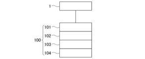
- FIG. 1 is a schematic diagram showing a basic configuration of the present invention.
- FIG. 1 is a schematic diagram showing a specific example of a dielectric spectroscopy sensor using a coaxial probe.
- 1 is a schematic diagram showing a state in which a measurement sample is placed on an end face of a dielectric spectroscopy sensor (coaxial probe).
- FIG. 1 is a schematic diagram showing a specific embodiment of a dielectric spectroscopy sensor of the present invention.
- 13 is a graph showing a comparison result of the attenuation rate of the electric field from the end face of the coaxial probe. This is a calibration curve for a coaxial probe with a 2.5 mm aperture. This is a calibration curve for a coaxial probe with an aperture of 700 ⁇ m.
- a method using electromagnetic waves in the microwave to millimeter wave band has been proposed because there is less scattering in the body compared to optical methods such as near-infrared light, and the energy of one photon is low.
- the method using a coaxial probe can use easily available samples such as water to calibrate the measuring device, and it is possible to measure the dielectric constant of the measured sample by contacting the sample to be measured with the probe end without requiring special processing of the material, so it has traditionally been applied to the measurement of samples whose component concentrations in living organisms are to be evaluated.
- the dielectric spectroscopy sensor of the present invention is characterized in that the measurement area in a living body measured by the sensor is considered to have a four-layer structure consisting of the stratum corneum, epidermis layer, dermis layer, and subcutaneous tissue layer, and has a structure in which the leakage electric field from the sensor is attenuated by the time it reaches the dermis layer. Due to this feature, the same calibration model can be used between living bodies with different dielectric constants of the subcutaneous tissue, making it possible to accurately estimate the concentrations of components in the living body.
- the dielectric spectroscopic sensor 1 of this embodiment measures the measurement target sample 100.
- the dielectric spectroscopic sensor 1 is a passive device whose reflection or transmission characteristics change when it comes into contact with the measurement target sample 100.
- the passive device may be a transmission line such as a coaxial probe, a microstrip line, a coplanar line, or a coplanar stop, or a device that generates resonance due to a structure such as an antenna, a split ring resonator, or a cavity resonator.
- the electromagnetic wave When an electromagnetic wave is input to the dielectric spectroscopic sensor 1, the electromagnetic wave is transmitted through the dielectric spectroscopic sensor 1 while generating a leakage electric field near the dielectric spectroscopic sensor 1, and is reflected or transmitted from the dielectric spectroscopic sensor 1.
- the transmission characteristics in the dielectric spectroscopic sensor 1 change depending on the dielectric constant of the area where the leakage electric field is generated, so that the transmission characteristics of the dielectric spectroscopic sensor 1 change when the dielectric constant in the measurement target sample 100 changes due to fluctuations in the component concentration, making it possible to create a quantitative model of the component concentration.
- the measurement target sample 100 is assumed to be skin.
- the dielectric constant of the measurement target sample 100 is not uniform, but is considered to be composed of four layers, namely, the stratum corneum 101, the epidermis layer 102, the dermis layer 103, and the subcutaneous tissue layer 104, and the thickness of each layer is, for example, 10 to 50 ⁇ m for the stratum corneum 101, 50 to 300 ⁇ m for the epidermis layer 102, and 1 to 3 mm for the dermis layer 103.
- the thickness of each layer may be changed depending on the measurement site, and the presence or absence of each layer may be changed depending on the organism to be measured. As shown in Caspers et al. (2001) (Non-Patent Document 4) and Sasaki et al.
- the dielectric constant of the stratum corneum, epidermis layer, and dermis layer is dominated by tissue fluids such as interstitial fluid and intracellular fluid, and is approximately 30 to 50%, 60 to 70%, and 60 to 70%, respectively.
- the dielectric constant of liquids is high at around 80 in the microwave band, while the dielectric constant of the subcutaneous tissue layer is relatively low because it contains fat and protein.
- the dielectric constant of the subcutaneous tissue layer changes depending on an individual's body fat percentage, and changes in transmission characteristics due to the interaction between the leakage electric field of the dielectric spectroscopy sensor and the subcutaneous tissue layer result in an error in the calibration model.
- the moisture content in the dermis and epidermis is thought to be kept constant due to the barrier function of the skin.
- the effect of changes in the dielectric constant of the subcutaneous tissue can be suppressed, and the same calibration model can be used to quantify the concentration of components with high accuracy for living organisms with different characteristics of the subcutaneous tissue layer.
- the dielectric spectroscopy sensor 1 shown in Figure 2A is a coaxial device (coaxial probe) consisting of an outer conductor 12, an inner conductor 13, a dielectric 14, and a high-frequency coaxial connector 11.
- the characteristic impedance of the dielectric spectroscopy sensor 1 is given by equation (1).
- Zcoax, ⁇ c , D, and d represent the characteristic impedance, the dielectric constant of the dielectric 14, the outer diameter of the dielectric 14, and the outer diameter of the inner conductor 13, respectively.
- FIG. 2B shows the state in which the measurement target sample (MUT) 100 is placed on the end face of the dielectric spectroscopy sensor 1 (coaxial probe).
- the admittance of the end face of the dielectric spectroscopy sensor 1 in the state shown in FIG. 2B can be expressed by (2) and depends on the dielectric constant ⁇ r of the measurement target sample (MUT) 100.
- k 0 is the wave number at the measurement frequency
- ⁇ r and ⁇ are the dielectric constant of the measurement target sample (MUT) and the propagation constant within the MUT, respectively
- J 0 (x) is the zeroth-order Bessel function
- a and b are the radius of the outer diameter of the inner conductor and the radius of the inner diameter of the outer conductor of the coaxial sensor, respectively.
- Equation (2) only considers the electromagnetic waves in the TEM (Transverse Electro Magnetic) mode inside the coaxial probe. It is also possible to use an equation using a higher mode instead, or to calculate the admittance using electromagnetic field simulation.
- the measurement sample 100 placed on the dielectric spectroscopy sensor 1 is regarded as a material consisting of four layers, namely, the stratum corneum 101, the epidermis 102, the dermis 103, and the subcutaneous tissue layer 104, and the admittance can be calculated based on the formula (2).
- the thickness of the dermis 103 is changed by, for example, about 10 ⁇ m, and when the calculated admittance changes, it means that the leakage electric field 20 from the dielectric spectroscopy sensor 1 (coaxial probe) has reached the subcutaneous tissue layer 104.
- the aperture of the dielectric spectroscopy sensor 1 (coaxial probe) is narrowed to maintain the relationship of formula (1), and an aperture is used such that the amount of change in admittance when the thickness of the dermis 103 changes is equal to or less than a certain value, for example, 0.5% or less.
- the S11 parameter input reflection coefficient indicating the ratio of the signal reflected at the input terminal to the signal input to the input terminal
- electromagnetic field simulation may be used.
- the attenuation rate of the electric field (leakage electric field 20) leaking from the end face of the dielectric spectroscopy sensor 1 (coaxial probe) can be calculated, and an opening can be selected so that the electric field strength at the dermis layer 103-subcutaneous tissue layer 104 interface is attenuated by 95% or more, preferably 99% or more.
- Figure 4 shows the results of a comparison between the electric field attenuation rate from the end face of the dielectric spectroscopy sensor of the present invention, which is a coaxial probe with an aperture of 700 ⁇ m, and the electric field attenuation rate from the end face of a commercially available coaxial probe with an aperture of 2.5 mm.
- the relative dielectric constant of the dielectric of the coaxial probe was set to 3.5.
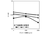
- Figures 5A and 5B show the results of calibration of component concentrations in biological samples in which the dielectric constant of the subcutaneous tissue layer is changed, using a coaxial probe with an aperture of 2.5 mm or 700 ⁇ m.
- Figures 5A and 5B show a calibration curve of glucose concentration-S11 parameter created from the change in the S11 parameter at a frequency of 7.7 GHz, after performing an electromagnetic field simulation assuming that the dielectric constant of the subcutaneous tissue layer in Figure 3 is changed from 3 to 5, and the glucose concentration in the interstitial fluid contained in the dermis and epidermis is changed from 0 to 2000 mg/dL.
- Figure 5A is the calibration curve for a coaxial probe with an aperture of 2.5 mm
- Figure 5B is the calibration curve for a dielectric spectroscopy sensor, which is a coaxial probe with an aperture of 700 ⁇ m designed based on the present invention.
- the vertical scale is 1.0 dB. It can be seen that the present invention reduces the variation in S parameters (parameters that represent the characteristics of a circuit by the degree of reflection and transmission of the wave when an AC signal is considered as a wave), reduces the effect of changes in the dielectric constant of the subcutaneous tissue layer, and enables highly accurate quantification of component concentrations when a single calibration model is created.
- the dielectric spectroscopic sensor of the present invention can be used in devices for measuring the dielectric constant of solutions present in humans or animals, and in devices for measuring the dielectric constant of solutions or semi-solid materials taken from humans or animals.
Landscapes
- Health & Medical Sciences (AREA)
- Life Sciences & Earth Sciences (AREA)
- Physics & Mathematics (AREA)
- Pathology (AREA)
- General Health & Medical Sciences (AREA)
- Analytical Chemistry (AREA)
- Heart & Thoracic Surgery (AREA)
- Chemical & Material Sciences (AREA)
- General Physics & Mathematics (AREA)
- Immunology (AREA)
- Electromagnetism (AREA)
- Biophysics (AREA)
- Engineering & Computer Science (AREA)
- Biomedical Technology (AREA)
- Biochemistry (AREA)
- Medical Informatics (AREA)
- Molecular Biology (AREA)
- Surgery (AREA)
- Animal Behavior & Ethology (AREA)
- Public Health (AREA)
- Veterinary Medicine (AREA)
- Measurement Of The Respiration, Hearing Ability, Form, And Blood Characteristics Of Living Organisms (AREA)
Abstract
角質層(101)、表皮層(102)、真皮層(103)、及び皮下組織層(104)がこの順に積層してなる4層構造を有する測定対象試料(100)の複素誘電率を角質層(101)の側から測定するための誘電分光センサ(1)であって、誘電分光センサ(1)は測定対象試料(100)と接することで反射特定又は透過特性が変化するパッシブデバイスを用いており、誘電分光センサ(1)からの漏洩電界の電界強度を測定対象試料(100)の測定部位の真皮層(103)と皮下組織層(104)との界面において95%以上減衰させる構造であることを特徴とする、誘電分光センサ(1)。
Description
本発明は、液体、半固体材料又は生体の複素誘電率を測定する技術に関する。
高齢化が進み、成人病に対する対応が大きな課題になっている。血糖値などの検査は血液の採取が必要なために患者にとって大きな負担である。そのため、血液を採取しない非侵襲な成分濃度測定装置が注目されている。
非侵襲な成分濃度測定装置としては、近赤外光などの光学的な手法と比べ生体内での散乱が少ない、1フォトンの持つエネルギーが低い、などの理由からマイクロ波-ミリ波帯の電磁波を用いた手法が提案されている。
例えば、非特許文献1に示される共振構造を用いた手法がある。この手法では、アンテナ又は共振器などのQ値の高いデバイスと測定試料を接触させ、共振周波数周辺の周波数特性を測定する。共振周波数はデバイスの周囲の複素誘電率により決定されるため、共振周波数のシフト量と成分濃度との間の相関を予め予測することにより、共振周波数のシフト量から成分濃度を推定する。
マイクロ波-ミリ波帯の電磁波を用いた他の手法としては、特許文献1に示す誘電分光法が提案されている。誘電分光法は、皮膚内に電磁波を照射し、測定対象である血液成分、例えば、グルコース分子と水の相互作用に従い、電磁波を吸収させ、電磁波の振幅及び位相を観測する。観測される電磁波の周波数に対する振幅及び位相から、誘電緩和スペクトルを算定する。誘電緩和スペクトルは、一般的には、Cole-Cole式に基づき緩和カーブの線形結合として表現し、複素誘電率を算定する。生体成分の計測では、例えば血液中に含まれるグルコース又はコレステロール等の血液成分の量に複素誘電率は相関があり、その変化に対応した電気信号(振幅及び位相)として測定される。複素誘電率変化と成分濃度との相関を予め測定することによって検量モデルを構築し、計測した誘電緩和スペクトルの変化から成分濃度の検量を行う。
いずれの手法を用いる場合でも、対象となる成分と相関の強い周波数帯を選定することにより測定感度の向上が期待できるため、あらかじめ広帯域な誘電分光により誘電率の変化を測定しておくことは重要である。
誘電分光法の中でも、非特許文献2及び3、並びに特許文献2に示すような同軸プローブ(開放終端同軸プローブ又は開放終端同軸ライン)を用いた手法は測定器の校正に水などの入手が容易な試料を用いることができ、また、材料の特殊な加工を必要とせずプローブ端面に被測定試料を接触させることで測定試料の誘電率を測定することが可能であるため、生体に含まれる成分濃度を評価したい試料の測定に適している。
非特許文献6には、センサによる生体内の測定領域を角質層、表皮層、真皮層、及び皮下組織層の4層からなる構造であるとみなすことが開示されている。
M. Hofmann, G. Fischer, R. Weigel, and D. Kissinger, "Microwave-Based Noninvasive Concentration Measurements for Biomedical Applications", IEEE Trans. Microwave Theory and Techniques, Vol.61, No.5, pp. 2195-2203,2013
J P. Grant, R N. Clarke, G T. SYymm and N M. Spyrou, "A critical study of the open-ended coaxial line sensor technique for RF and microwave complex permittivity measurements", J. Phys. E: Sci. Instrum, Vol.22, pp. 757-770, 1989
T.P. Marsland, and S. Evans "Dielectric measurements with an open-ended coaxial probe", IEE Proceedings, Vol. 134, No.4, 1987
Peter J. Caspers, Gerald W. Lucassen, Elizabeth A. Carter, Hajo A. Bruining, and Gerwin J. Puppels, "In Vivo Confocal Raman Microspectroscopy of the Skin:Noninvasive Determination of Molecular ConcentrationProfles", THE JOURNAL OF INVESTIGATIVE DERMATOLOGY, VOL. 116, NO. 3 MARCH 2001
K. Sasaki, K. Li and T. Nagaoka, "Human Skin Exposure to Terahertz Waves from 0.1 to 1 THz: Statistical Assessments Using Multilayered Planar Models", Proc. In International Microwave Biomedical Conference 2022
Sonja Huclova1, Daniel Erni, and Juerg Froehlich, "Modelling and validation of dielectric properties of human skin in the MHz region focusing on skin layer morphology and material composition", Journal of Physics D: Applied Physics, Vol. 45, 025301, 2012
しかしながら、これらのセンサを用いて、非侵襲的に間質液中の成分濃度を測定する際には、皮下組織の誘電率は体脂肪率などにより変化が生じており、同軸プローブから照射される電磁波の反射、吸収特性に影響することで検量モデルが変化し成分濃度推定時の誤差が増加するという課題があった。
本発明の誘電分光センサは、角質層、表皮層、真皮層、及び皮下組織層がこの順に積層してなる4層構造を有する測定対象試料の複素誘電率を前記角質層の側から測定するための誘電分光センサであって、前記誘電分光センサは前記測定対象試料と接することで反射特定又は透過特性が変化するパッシブデバイスを用いており、前記誘電分光センサからの漏洩電界の電界強度を前記測定対象試料の測定部位の前記真皮層と前記皮下組織層との界面において95%以上減衰させる構造であることを特徴とする。
本発明の複素誘電率の測定方法は、角質層、表皮層、真皮層、及び皮下組織層がこの順に積層してなる4層構造を有する測定対象試料の複素誘電率の測定方法であって、前記誘電分光センサを前記角質層の表面に接触させる工程及び前記誘電分光センサに測定周波数の交流電流を流す測定工程を含むことを特徴とする。
本発明は、非侵襲的に間質液中の成分濃度を推定する際の、皮下組織の誘電率のばらつきの影響を抑制し、成分濃度推定時の誤差を低減するという効果を奏する。
以下では本発明の実施形態について詳細に説明するが、本発明は後述する実施形態に限定されるものではなく、本発明の要旨を逸脱しない限り種々の変形が可能である。
血液を採取しない非侵襲な成分濃度測定装置がとして、近赤外光などの光学的な手法と比べ生体内での散乱が少ない、1フォトンの持つエネルギーが低い、などの理由からマイクロ波-ミリ波帯の電磁波を用いた手法が提案されていた。マイクロ波-ミリ波帯の電磁波を用いた手法のひとつである誘電分光法の中でも、同軸プローブを用いた手法は、測定器の校正に水などの入手が容易な試料を用いることができ、また、材料の特殊な加工を必要とせずプローブ端面に被測定試料を接触させることで測定試料の誘電率を測定することが可能であるため、従来、生体に含まれる成分濃度を評価したい試料の測定に適用されてきた。
しかしながら、非侵襲的に間質液中の成分濃度を測定する際には、皮下組織の誘電率は体脂肪率などにより変化が生じており、同軸プローブから照射される電磁波の反射、吸収特性に影響することで検量モデルが変化し成分濃度推定時の誤差が増加するという問題があった。
本発明の誘電分光センサは、センサによる生体内の測定領域を角質層、表皮層、真皮層、皮下組織層の4層からなる構造とみなし、センサからの漏洩電界が真皮層までで減衰するような構造を持つことを特徴とし、当該特徴により、皮下組織の誘電率が異なる生体間においても同一の検量モデルが使用可能であり、生体中の成分濃度を精度よく推定することが可能となる。
しかしながら、非侵襲的に間質液中の成分濃度を測定する際には、皮下組織の誘電率は体脂肪率などにより変化が生じており、同軸プローブから照射される電磁波の反射、吸収特性に影響することで検量モデルが変化し成分濃度推定時の誤差が増加するという問題があった。
本発明の誘電分光センサは、センサによる生体内の測定領域を角質層、表皮層、真皮層、皮下組織層の4層からなる構造とみなし、センサからの漏洩電界が真皮層までで減衰するような構造を持つことを特徴とし、当該特徴により、皮下組織の誘電率が異なる生体間においても同一の検量モデルが使用可能であり、生体中の成分濃度を精度よく推定することが可能となる。
本発明の一実施形態を図1に示す。本実施形態の誘電分光センサ1は測定対象試料100を測定する。誘電分光センサ1としては、測定対象試料100と接することで反射特性又は透過特性の変化するパッシブデバイスを用いる。前記パッシブデバイスとしては、例えば同軸プローブ、マイクロストリップ線路、コプレーナ線路、若しくはコプレーナストップなどの伝送線路、又はアンテナ、スプリットリング共振器、若しくは空洞共振器といった構造により共振の生じるデバイスを用いる。誘電分光センサ1に電磁波が入力されると、電磁波は誘電分光センサ1近傍に漏洩電界を生じさせながら誘電分光センサ1内を伝送し、誘電分光センサ1から反射又は透過する。このとき、誘電分光センサ1内の伝送特性は漏洩電界が生じている領域の誘電率により変化するため、成分濃度の変動により測定対象試料100内の誘電率が変化することで誘電分光センサ1の伝送特性が変化し、成分濃度の定量モデルが作成可能となる。測定対象試料100は皮膚を想定している。測定対象試料100の誘電率は一様ではなく、角質層101、表皮層102、真皮層103、及び皮下組織層104の4層からなると考え、各層の厚みは、例えば角質層101は10~50μm、表皮層102は50~300μm、真皮層103は1~3mm程度であるとする。測定部位により各層の厚さを変更してもよいし、測定対象の生物に応じて各層の有無を変更してもよい。Caspers et al. (2001)(非特許文献4)及びSasaki et al. (2022)(非特許文献5)に示すように、角質層、表皮層、及び真皮層は細胞間質液及び細胞内液等の組織液由来の誘電率が支配的であり、それぞれ30~50%、60~70%、60~70%程度とする。液体の誘電率はマイクロ波帯では80程度と高く、皮下組織層は脂肪及びタンパク質などが含まれるため、その誘電率は相対的に低い値となる。ここで、皮下組織層の誘電率は個人の体脂肪率などにより変化が生じるため、誘電分光センサの漏洩電界と皮下組織層の相互作用による伝送特性の変化が検量モデルの誤差として生じることになる。一方で、真皮層及び表皮層における水分量は皮膚のバリア機能により水分量が一定に保たれていると考えられる。このとき、誘電分光センサから漏洩する電界の分布を表皮層までにとどめることにより、皮下組織の誘電率変化の影響を抑制し、同一の検量モデルを用いて皮下組織層の特性の異なる生体に対して高精度な成分濃度定量が可能となる。
本発明の具体的な実施態様として、同軸プローブを用いた誘電分光センサの例を図2Aに示す。
図2Aに示す誘電分光センサ1は、外部導体12、内部導体13、誘電体14、及び高周波同軸コネクタ11からなる同軸構造のデバイス(同軸プローブ)である。
誘電分光センサ1の特性インピーダンスは式(1)により示される。

ここで、Zcoax、εc、D、及びdは、それぞれ、特性インピーダンス、誘電体14の誘電率、誘電体14の外径、及び内部導体13の外径を示す。
図2Bに、測定対象試料(MUT)100を誘電分光センサ1(同軸プローブ)の端面に設置した状態を示す。
図2Bに示す状態での誘電分光センサ1の端面のアドミタンスは(2)で表すことができ、測定対象試料(MUT)100の誘電率εrに依存する。

ここで、k0は測定周波数における波数であり、εr及びγはそれぞれ測定対象試料(MUT)の誘電率及びMUT内の伝搬定数であり、J0(x)は0次ベッセル関数であり、a及びbはそれぞれ同軸センサの内部導体外径の半径及び外部導体内径の半径である。
(2)式は同軸プローブ内のTEM(Transverse Electro Magnetic:横電磁界)モードの電磁波のみを考慮した式であり、代わりに高次モードを用いた式を用いたり、電磁界シミュレーションを用いてアドミタンスを算出したりすることも可能である。
次に、本発明の実施態様を図3に示す。本実施態様では、誘電分光センサ1(同軸プローブ)に設置する測定対象試料100を角質層101、表皮層102、真皮層103、及び皮下組織層104の4層からなる材料とみなし、式(2)の式に基づきアドミタンスを算出可能である。ここで、真皮層103の厚みを、例えば10μm程度変化させ、算出されるアドミタンスが変化している時には誘電分光センサ1(同軸プローブ)からの漏洩電界20が皮下組織層104に到達していることを意味しているため、式(1)の関係を維持するように誘電分光センサ1(同軸プローブ)の開口を狭くし、真皮層103の厚みが変化した際のアドミタンスの変化量が一定値以下、例えば、0.5%以下となるような開口を用いる。アドミタンスの理論式を用いる代わりに電磁界シミュレーションにより算出されるS11パラメータ(入力端子に入力した信号に対して入力端子で反射される信号の割合を示す入力反射係数)を用いてもよい。電磁界シミュレーションを用いる場合には、誘電分光センサ1(同軸プローブ)の端面から漏洩する電界(漏洩電界20)の減衰率を算出し、真皮層103-皮下組織層104界面における電界強度を95%以上、好ましくは99%以上減衰させるように開口を選定してもよい。
図4に、開口を700μmとした同軸プローブである本発明の誘電分光センサの端面からの電界の減衰率と、市販品相当の2.5mmの開口を持つ同軸プローブの端面からの電界の減衰率とを比較した結果を示す。このとき、同軸プローブの誘電体の比誘電率は3.5とした。本発明の誘電分光センサ(同軸プローブ)では、真皮層までで電界が99.9%減衰している。
2.5mm又は700μmの開口を持つ同軸プローブを用いて、皮下組織層の誘電率が変化している生体試料における成分濃度の検量結果を図5A及び図5Bに示す。図5A及び図5Bは、図3における皮下組織層の誘電率を3から5まで、真皮層及び表皮層に含まれる間質液中のグルコース濃度を0から2000mg/dLまで変化することを想定した電磁界シミュレーションを実施し、周波数7.7GHzにおけるS11パラメータの変化からグルコース濃度-S11パラメータの検量線を作成したものである。
図5Aは2.5mmの開口を持つ同軸プローブの検量線であり、図5Bは本発明に基づき設計した700μmの開口を持つ同軸プローブである誘電分光センサの検量線である。図5A及び図5Bは、いずれも縦軸のスケールは1.0dBとしている。本発明によりSパラメータ(交流信号を波と捉えたとき、その波動の反射及び伝送度合いで回路の特性を表わしたパラメータ)のばらつきが抑制され、皮下組織層の誘電率変化の影響が抑制され、単一の検量モデルを作製した際には高精度で成分濃度の定量が可能となることが分かる。
本発明の誘電分光センサは、人間又は動物に存在する溶液の誘電率測定装置、及び、人間又は動物から採取した溶液又は半固体材料の誘電率測定装置に利用可能である。
1…誘電分光センサ
11…高周波同軸コネクタ
12…外部導体
13…内部導体
14…誘電体
20…漏洩電界
100…測定対象試料(MUT)
101…角質層
102…表皮層
103…真皮層
104…皮下組織層
11…高周波同軸コネクタ
12…外部導体
13…内部導体
14…誘電体
20…漏洩電界
100…測定対象試料(MUT)
101…角質層
102…表皮層
103…真皮層
104…皮下組織層
Claims (4)
- 角質層、表皮層、真皮層、及び皮下組織層がこの順に積層してなる4層構造を有する測定対象試料の複素誘電率を前記角質層の側から測定するための誘電分光センサであって、
前記誘電分光センサは前記測定対象試料と接することで反射特定又は透過特性が変化するパッシブデバイスを用いており、
前記誘電分光センサからの漏洩電界の電界強度を前記測定対象試料の測定部位の前記真皮層と前記皮下組織層との界面において95%以上減衰させる構造であることを特徴とする、誘電分光センサ。 - 前記パッシブデバイスが、同軸プローブ、マイクロストリップ線路、コプレーナ線路、コプレーナストップ、アンテナ、スプリットリング共振器、及び空洞共振器からなる群から選択されるいずれか1種である、請求項1に記載の誘電分光センサ。
- 前記パッシブデバイスが同軸プローブであり、外部導体、内部導体、誘電体、及び高周波同軸コネクタからなる同軸構造を有する、請求項1に記載の誘電分光センサ。
- 角質層、表皮層、真皮層、及び皮下組織層がこの順に積層してなる4層構造を有する測定対象試料の複素誘電率の測定方法であって、
請求項1~3の何れか一項に記載の誘電分光センサを前記角質層の表面に接触させる工程、
前記誘電分光センサに測定周波数の交流電流を流す測定工程
を含む、測定方法。
Priority Applications (2)
| Application Number | Priority Date | Filing Date | Title |
|---|---|---|---|
| PCT/JP2023/020787 WO2024252456A1 (ja) | 2023-06-05 | 2023-06-05 | 誘電分光センサ及び複素誘電率の測定方法 |
| JP2025525433A JPWO2024252456A1 (ja) | 2023-06-05 | 2023-06-05 |
Applications Claiming Priority (1)
| Application Number | Priority Date | Filing Date | Title |
|---|---|---|---|
| PCT/JP2023/020787 WO2024252456A1 (ja) | 2023-06-05 | 2023-06-05 | 誘電分光センサ及び複素誘電率の測定方法 |
Publications (1)
| Publication Number | Publication Date |
|---|---|
| WO2024252456A1 true WO2024252456A1 (ja) | 2024-12-12 |
Family
ID=93795239
Family Applications (1)
| Application Number | Title | Priority Date | Filing Date |
|---|---|---|---|
| PCT/JP2023/020787 Ceased WO2024252456A1 (ja) | 2023-06-05 | 2023-06-05 | 誘電分光センサ及び複素誘電率の測定方法 |
Country Status (2)
| Country | Link |
|---|---|
| JP (1) | JPWO2024252456A1 (ja) |
| WO (1) | WO2024252456A1 (ja) |
Citations (9)
| Publication number | Priority date | Publication date | Assignee | Title |
|---|---|---|---|---|
| JPH11100320A (ja) * | 1997-09-29 | 1999-04-13 | Risuburan:Kk | 皮膚外用剤 |
| JP2002060349A (ja) * | 2000-08-17 | 2002-02-26 | Zenzaburo Hara | 皮膚外用剤 |
| JP2005272341A (ja) * | 2004-03-24 | 2005-10-06 | Kinka:Kk | 栄養クリーム |
| US20090204346A1 (en) * | 2008-02-11 | 2009-08-13 | Schlumberger Technology Corporation | System and method for measuring properties of liquid in multiphase mixtures |
| JP2015163862A (ja) * | 2014-01-31 | 2015-09-10 | 富士フイルム株式会社 | 光断層画像撮像装置および光断層画像撮像装置を用いたヒト肌の計測方法 |
| WO2021205503A1 (ja) * | 2020-04-06 | 2021-10-14 | 日本電信電話株式会社 | 誘電分光測定装置および方法 |
| WO2022153490A1 (ja) * | 2021-01-15 | 2022-07-21 | 日本電信電話株式会社 | 誘電率の測定手法 |
| JP2022109198A (ja) * | 2021-01-14 | 2022-07-27 | 由利子 沓掛 | 光触媒活性様式付き塗擦保護剤および塗擦保護膜 |
| JP2023047638A (ja) * | 2021-09-27 | 2023-04-06 | タクセル株式会社 | マイクロニードルアレイ穿刺用デバイス |
-
2023
- 2023-06-05 JP JP2025525433A patent/JPWO2024252456A1/ja active Pending
- 2023-06-05 WO PCT/JP2023/020787 patent/WO2024252456A1/ja not_active Ceased
Patent Citations (9)
| Publication number | Priority date | Publication date | Assignee | Title |
|---|---|---|---|---|
| JPH11100320A (ja) * | 1997-09-29 | 1999-04-13 | Risuburan:Kk | 皮膚外用剤 |
| JP2002060349A (ja) * | 2000-08-17 | 2002-02-26 | Zenzaburo Hara | 皮膚外用剤 |
| JP2005272341A (ja) * | 2004-03-24 | 2005-10-06 | Kinka:Kk | 栄養クリーム |
| US20090204346A1 (en) * | 2008-02-11 | 2009-08-13 | Schlumberger Technology Corporation | System and method for measuring properties of liquid in multiphase mixtures |
| JP2015163862A (ja) * | 2014-01-31 | 2015-09-10 | 富士フイルム株式会社 | 光断層画像撮像装置および光断層画像撮像装置を用いたヒト肌の計測方法 |
| WO2021205503A1 (ja) * | 2020-04-06 | 2021-10-14 | 日本電信電話株式会社 | 誘電分光測定装置および方法 |
| JP2022109198A (ja) * | 2021-01-14 | 2022-07-27 | 由利子 沓掛 | 光触媒活性様式付き塗擦保護剤および塗擦保護膜 |
| WO2022153490A1 (ja) * | 2021-01-15 | 2022-07-21 | 日本電信電話株式会社 | 誘電率の測定手法 |
| JP2023047638A (ja) * | 2021-09-27 | 2023-04-06 | タクセル株式会社 | マイクロニードルアレイ穿刺用デバイス |
Non-Patent Citations (1)
| Title |
|---|
| MASATO NAKAMURA, TAKURO TAJIMA, NORIKO SEYAMA, YOSHIYO WAKI: "CS-2-3: In vivo verification of glucose sensing in interstitial fluid using dielectric spectroscopy -Effect of coaxial probe aperture during transcutaneous measurement-", LECTURE PROCEEDINGS 1 OF THE 2019 ELECTRONICS SOCIETY CONFERENCE OF IEICE; 2019.09.10-13, IEICE, JP, 10 September 2019 (2019-09-10) - 13 September 2019 (2019-09-13), JP, pages S - S-21, XP009559436 * |
Also Published As
| Publication number | Publication date |
|---|---|
| JPWO2024252456A1 (ja) | 2024-12-12 |
Similar Documents
| Publication | Publication Date | Title |
|---|---|---|
| Juan et al. | Concentration measurement of microliter-volume water–glucose solutions using $ Q $ factor of microwave sensors | |
| Cherkasova et al. | Noninvasive blood glucose monitoring in the terahertz frequency range | |
| JP7447990B2 (ja) | 誘電分光測定装置および方法 | |
| US11839468B2 (en) | Component concentration measurement device and component concentration measurement method | |
| JP6849630B2 (ja) | 成分濃度測定装置および成分濃度測定方法 | |
| Xiao et al. | Precise noninvasive estimation of glucose using UWB microwave with improved neural networks and hybrid optimization | |
| JP6288717B2 (ja) | 成分濃度分析方法 | |
| Malik et al. | Minimally invasive implant type electromagnetic biosensor for continuous glucose monitoring system: In vivo evaluation | |
| Wang et al. | Noninvasive, intelligent blood glucose monitoring on fingertip using dual-band fusion and LSTM-R network | |
| Zeising et al. | Towards realisation of a non-invasive blood glucose sensor using microstripline | |
| Mansour et al. | A novel approach to non-invasive blood glucose sensing based on a defected ground structure | |
| Kandwal et al. | Designing highly sensitive microwave antenna sensor with novel model for noninvasive glucose measurements | |
| Rangaiah et al. | Preliminary analysis of burn degree using non-invasive microwave spiral resonator sensor for clinical applications | |
| Shimonov et al. | Electromagnetic property characterization of biological tissues at D-band | |
| Mansour et al. | A novel biosensor for non-invasive blood glucose measurement based on double square complimentary split ring resonator | |
| Kandwal et al. | Flexible surface plasmon based coupled triple band UHF-microwave sensor for glucose sensing application | |
| JP6807300B2 (ja) | 成分濃度測定方法及び成分濃度測定装置 | |
| WO2024252456A1 (ja) | 誘電分光センサ及び複素誘電率の測定方法 | |
| Mishra et al. | A rectangular dielectric resonator based microwave sensor for non-invasive blood glucose sensing applications | |
| JP7680694B2 (ja) | 誘電率測定方法及び短絡標準体 | |
| Parkhomenko et al. | Analysis of dielectric properties of blood and development of a resonator method for noninvasive measuring of glucose content in blood | |
| Zakaria et al. | Improving Sensitivity of Noninvasive Blood Glucose Microwave Sensor Via Substrate Selection | |
| WO2024257177A1 (ja) | 誘電分光センサ及び複素誘電率の測定方法 | |
| Recha et al. | Enhancing measurement specificity in biological samples with differential probing analysis | |
| Aminuzzaman et al. | Non-Invasive Glucose Concentration Measurement Using a Metamaterial Based Biosensor |
Legal Events
| Date | Code | Title | Description |
|---|---|---|---|
| 121 | Ep: the epo has been informed by wipo that ep was designated in this application |
Ref document number: 23940564 Country of ref document: EP Kind code of ref document: A1 |
|
| ENP | Entry into the national phase |
Ref document number: 2025525433 Country of ref document: JP Kind code of ref document: A |
|
| NENP | Non-entry into the national phase |
Ref country code: DE |