WO2024248142A1 - 接合構造体の製造方法、積層体の製造方法及び接合方法 - Google Patents
接合構造体の製造方法、積層体の製造方法及び接合方法 Download PDFInfo
- Publication number
- WO2024248142A1 WO2024248142A1 PCT/JP2024/020076 JP2024020076W WO2024248142A1 WO 2024248142 A1 WO2024248142 A1 WO 2024248142A1 JP 2024020076 W JP2024020076 W JP 2024020076W WO 2024248142 A1 WO2024248142 A1 WO 2024248142A1
- Authority
- WO
- WIPO (PCT)
- Prior art keywords
- coating film
- joined
- bonded
- laminate
- bonded body
- Prior art date
- Legal status (The legal status is an assumption and is not a legal conclusion. Google has not performed a legal analysis and makes no representation as to the accuracy of the status listed.)
- Ceased
Links
Images

Classifications
-
- H—ELECTRICITY
- H10—SEMICONDUCTOR DEVICES; ELECTRIC SOLID-STATE DEVICES NOT OTHERWISE PROVIDED FOR
- H10W—GENERIC PACKAGES, INTERCONNECTIONS, CONNECTORS OR OTHER CONSTRUCTIONAL DETAILS OF DEVICES COVERED BY CLASS H10
- H10W72/00—Interconnections or connectors in packages
- H10W72/071—Connecting or disconnecting
- H10W72/073—Connecting or disconnecting of die-attach connectors
- H10W72/07331—Connecting techniques
- H10W72/07332—Compression bonding, e.g. thermocompression bonding
-
- B—PERFORMING OPERATIONS; TRANSPORTING
- B22—CASTING; POWDER METALLURGY
- B22F—WORKING METALLIC POWDER; MANUFACTURE OF ARTICLES FROM METALLIC POWDER; MAKING METALLIC POWDER; APPARATUS OR DEVICES SPECIALLY ADAPTED FOR METALLIC POWDER
- B22F1/00—Metallic powder; Treatment of metallic powder, e.g. to facilitate working or to improve properties
-
- B—PERFORMING OPERATIONS; TRANSPORTING
- B22—CASTING; POWDER METALLURGY
- B22F—WORKING METALLIC POWDER; MANUFACTURE OF ARTICLES FROM METALLIC POWDER; MAKING METALLIC POWDER; APPARATUS OR DEVICES SPECIALLY ADAPTED FOR METALLIC POWDER
- B22F1/00—Metallic powder; Treatment of metallic powder, e.g. to facilitate working or to improve properties
- B22F1/10—Metallic powder containing lubricating or binding agents; Metallic powder containing organic material
- B22F1/107—Metallic powder containing lubricating or binding agents; Metallic powder containing organic material containing organic material comprising solvents, e.g. for slip casting
-
- B—PERFORMING OPERATIONS; TRANSPORTING
- B22—CASTING; POWDER METALLURGY
- B22F—WORKING METALLIC POWDER; MANUFACTURE OF ARTICLES FROM METALLIC POWDER; MAKING METALLIC POWDER; APPARATUS OR DEVICES SPECIALLY ADAPTED FOR METALLIC POWDER
- B22F7/00—Manufacture of composite layers, workpieces, or articles, comprising metallic powder, by sintering the powder, with or without compacting wherein at least one part is obtained by sintering or compression
- B22F7/02—Manufacture of composite layers, workpieces, or articles, comprising metallic powder, by sintering the powder, with or without compacting wherein at least one part is obtained by sintering or compression of composite layers
-
- B—PERFORMING OPERATIONS; TRANSPORTING
- B22—CASTING; POWDER METALLURGY
- B22F—WORKING METALLIC POWDER; MANUFACTURE OF ARTICLES FROM METALLIC POWDER; MAKING METALLIC POWDER; APPARATUS OR DEVICES SPECIALLY ADAPTED FOR METALLIC POWDER
- B22F7/00—Manufacture of composite layers, workpieces, or articles, comprising metallic powder, by sintering the powder, with or without compacting wherein at least one part is obtained by sintering or compression
- B22F7/02—Manufacture of composite layers, workpieces, or articles, comprising metallic powder, by sintering the powder, with or without compacting wherein at least one part is obtained by sintering or compression of composite layers
- B22F7/04—Manufacture of composite layers, workpieces, or articles, comprising metallic powder, by sintering the powder, with or without compacting wherein at least one part is obtained by sintering or compression of composite layers with one or more layers not made from powder, e.g. made from solid metal
-
- B—PERFORMING OPERATIONS; TRANSPORTING
- B22—CASTING; POWDER METALLURGY
- B22F—WORKING METALLIC POWDER; MANUFACTURE OF ARTICLES FROM METALLIC POWDER; MAKING METALLIC POWDER; APPARATUS OR DEVICES SPECIALLY ADAPTED FOR METALLIC POWDER
- B22F9/00—Making metallic powder or suspensions thereof
-
- H—ELECTRICITY
- H05—ELECTRIC TECHNIQUES NOT OTHERWISE PROVIDED FOR
- H05K—PRINTED CIRCUITS; CASINGS OR CONSTRUCTIONAL DETAILS OF ELECTRIC APPARATUS; MANUFACTURE OF ASSEMBLAGES OF ELECTRICAL COMPONENTS
- H05K1/00—Printed circuits
- H05K1/02—Details
- H05K1/14—Structural association of two or more printed circuits
-
- H—ELECTRICITY
- H05—ELECTRIC TECHNIQUES NOT OTHERWISE PROVIDED FOR
- H05K—PRINTED CIRCUITS; CASINGS OR CONSTRUCTIONAL DETAILS OF ELECTRIC APPARATUS; MANUFACTURE OF ASSEMBLAGES OF ELECTRICAL COMPONENTS
- H05K1/00—Printed circuits
- H05K1/02—Details
- H05K1/14—Structural association of two or more printed circuits
- H05K1/144—Stacked arrangements of planar printed circuit boards
-
- H—ELECTRICITY
- H05—ELECTRIC TECHNIQUES NOT OTHERWISE PROVIDED FOR
- H05K—PRINTED CIRCUITS; CASINGS OR CONSTRUCTIONAL DETAILS OF ELECTRIC APPARATUS; MANUFACTURE OF ASSEMBLAGES OF ELECTRICAL COMPONENTS
- H05K3/00—Apparatus or processes for manufacturing printed circuits
- H05K3/30—Assembling printed circuits with electric components, e.g. with resistors
- H05K3/32—Assembling printed circuits with electric components, e.g. with resistors electrically connecting electric components or wires to printed circuits
-
- H—ELECTRICITY
- H05—ELECTRIC TECHNIQUES NOT OTHERWISE PROVIDED FOR
- H05K—PRINTED CIRCUITS; CASINGS OR CONSTRUCTIONAL DETAILS OF ELECTRIC APPARATUS; MANUFACTURE OF ASSEMBLAGES OF ELECTRICAL COMPONENTS
- H05K3/00—Apparatus or processes for manufacturing printed circuits
- H05K3/30—Assembling printed circuits with electric components, e.g. with resistors
- H05K3/32—Assembling printed circuits with electric components, e.g. with resistors electrically connecting electric components or wires to printed circuits
- H05K3/34—Assembling printed circuits with electric components, e.g. with resistors electrically connecting electric components or wires to printed circuits by soldering
- H05K3/3465—Application of solder
- H05K3/3485—Application of solder paste, slurry or powder
-
- H—ELECTRICITY
- H05—ELECTRIC TECHNIQUES NOT OTHERWISE PROVIDED FOR
- H05K—PRINTED CIRCUITS; CASINGS OR CONSTRUCTIONAL DETAILS OF ELECTRIC APPARATUS; MANUFACTURE OF ASSEMBLAGES OF ELECTRICAL COMPONENTS
- H05K3/00—Apparatus or processes for manufacturing printed circuits
- H05K3/36—Assembling printed circuits with other printed circuits
-
- H—ELECTRICITY
- H05—ELECTRIC TECHNIQUES NOT OTHERWISE PROVIDED FOR
- H05K—PRINTED CIRCUITS; CASINGS OR CONSTRUCTIONAL DETAILS OF ELECTRIC APPARATUS; MANUFACTURE OF ASSEMBLAGES OF ELECTRICAL COMPONENTS
- H05K3/00—Apparatus or processes for manufacturing printed circuits
- H05K3/36—Assembling printed circuits with other printed circuits
- H05K3/368—Assembling printed circuits with other printed circuits parallel to each other
-
- H—ELECTRICITY
- H10—SEMICONDUCTOR DEVICES; ELECTRIC SOLID-STATE DEVICES NOT OTHERWISE PROVIDED FOR
- H10W—GENERIC PACKAGES, INTERCONNECTIONS, CONNECTORS OR OTHER CONSTRUCTIONAL DETAILS OF DEVICES COVERED BY CLASS H10
- H10W72/00—Interconnections or connectors in packages
- H10W72/071—Connecting or disconnecting
-
- H—ELECTRICITY
- H10—SEMICONDUCTOR DEVICES; ELECTRIC SOLID-STATE DEVICES NOT OTHERWISE PROVIDED FOR
- H10W—GENERIC PACKAGES, INTERCONNECTIONS, CONNECTORS OR OTHER CONSTRUCTIONAL DETAILS OF DEVICES COVERED BY CLASS H10
- H10W72/00—Interconnections or connectors in packages
- H10W72/071—Connecting or disconnecting
- H10W72/073—Connecting or disconnecting of die-attach connectors
- H10W72/07311—Treating the bonding area before connecting, e.g. by applying flux or cleaning
-
- H—ELECTRICITY
- H10—SEMICONDUCTOR DEVICES; ELECTRIC SOLID-STATE DEVICES NOT OTHERWISE PROVIDED FOR
- H10W—GENERIC PACKAGES, INTERCONNECTIONS, CONNECTORS OR OTHER CONSTRUCTIONAL DETAILS OF DEVICES COVERED BY CLASS H10
- H10W72/00—Interconnections or connectors in packages
- H10W72/071—Connecting or disconnecting
- H10W72/073—Connecting or disconnecting of die-attach connectors
- H10W72/07351—Connecting or disconnecting of die-attach connectors characterised by changes in properties of the die-attach connectors during connecting
Definitions
- the present invention relates to a method for manufacturing a bonded structure formed by bonding two objects to be bonded.
- the present invention also relates to a method for manufacturing a laminate to obtain a bonded structure and a method for bonding two objects to be bonded.
- power devices In recent years, semiconductor elements known as power devices have come to be widely used as power conversion and control devices, such as inverters. Unlike integrated circuits such as memory and microprocessors, power devices are designed to control high currents, and so generate a great deal of heat during operation. Therefore, the solder used to mount power devices must be heat resistant. However, the lead-free solder that is currently in main use has the disadvantage of being less heat resistant than regular lead-containing solder.
- Patent Document 1 describes a method in which a conductive paste containing metal particles is applied onto an electrode pattern, a semiconductor element is placed on top of it, and the conductive paste is heated while being pressurized by pressing down on the semiconductor element, to form a sintered layer of metal particles.
- the object of the present invention is to provide a manufacturing method for a bonded structure that can successfully bond objects to each other without causing the objects to shift position or fall off.
- the present invention provides a method for manufacturing a bonded structure in which a first bonded body and a second bonded body are bonded to each other via a bonding layer, comprising the steps of: applying a paste containing copper particles and an organic solvent to the first bonded body to form a coating film; a drying step for removing a part of the organic solvent contained in the coating film; a step of pressing the second object to be joined into the coating film so that a part of the second object to be joined is embedded in the coating film, thereby obtaining a laminate including the first object to be joined, the coating film, and the second object to be joined in this order; and heating the laminate.
- the average thickness of the coating film after the drying step and before the second bonded body is pressed into the coating film is defined as X ( ⁇ m);
- X The average thickness of the coating film after the drying step and before the second bonded body is pressed into the coating film
- Y The average distance from the upper surface of the first bonded body to the lower surface of the second bonded body in the state where the laminate is obtained.
- the present invention provides a method for producing a joint structure in which a pressing ratio P defined as 100-(Y/X ⁇ 100) is 1.0 or more and 50 or less.
- the present invention further provides a method for joining a first object to be joined and a second object to be joined, comprising the steps of: applying a paste containing copper particles and an organic solvent to the first bonded body to form a coating film; a drying step for removing a part of the organic solvent contained in the coating film; a step of pressing the second object to be joined into the coating film so that a part of the second object to be joined is embedded in the coating film, thereby obtaining a laminate including the first object to be joined, the coating film, and the second object to be joined in this order; and heating the laminate.
- the average thickness of the coating film after the drying step and before the second bonded body is pressed into the coating film is defined as X ( ⁇ m);
- X The average thickness of the coating film after the drying step and before the second bonded body is pressed into the coating film
- Y The average distance from the upper surface of the first bonded body to the lower surface of the second bonded body in the state where the laminate is obtained.
- the present invention provides a bonding method in which a pressing ratio P defined as 100-(Y/X ⁇ 100) is 1.0 or more and 50 or less.
- FIG. 1 is a process diagram showing one embodiment of the method for producing a bonded structure of the present invention (a process diagram up to the production of a laminate).
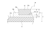
- FIG. 2 is a schematic diagram showing an enlarged view of a main part of a laminate in which a second object to be joined is pressed into a dried coating film.
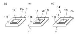
- 3(a) to 3(c) are schematic diagrams showing a method for measuring the values of X and Y in order to calculate the value of the pressing rate P defined as 100-(Y/X ⁇ 100).
- the present invention relates to a method for manufacturing a bonded structure in which two bonded bodies, i.e., a first bonded body and a second bonded body, are bonded via a bonding layer.
- the method is roughly divided into the following steps. (1) A step of applying a paste containing copper particles and an organic solvent to a first object to be joined to form a coating film. (2) A drying step for removing a portion of the organic solvent contained in the coating film. (3) A step of pressing the second object to be joined into the coating film so that a portion of the second object to be joined is embedded in the coating film, thereby obtaining a laminate including the first object to be joined, the coating film, and the second object to be joined. (4) A step of heating the laminate. Each step will be described below with reference to FIG.
- FIG. 1 is a process diagram showing one embodiment of a method for producing a joint structure of the present invention.
- a first object to be joined 11 is prepared, and a paste is applied onto one surface of the first object to be joined 11 to form a wet coating film 13a.
- the paste contains copper particles and an organic solvent.
- the method for applying the paste is not particularly limited.
- the wet coating film 13a can be formed by a screen printing method, a gravure printing method, a dispense printing method, a reverse coating method, a doctor blade method, or the like.
- the average thickness of the wet coating film 13a is preferably 18 ⁇ m or more, more preferably 20 ⁇ m or more, and even more preferably 25 ⁇ m or more. Furthermore, from the viewpoint of making the coating film easily smooth and preventing cracking of the coating film after drying, the average thickness of the wet coating film 13a is preferably 1000 ⁇ m or less, more preferably 800 ⁇ m or less, and even more preferably 500 ⁇ m or less.
- the average thickness of the wet coating film 13a can be calculated, for example, using a non-contact surface profiler that uses white light interference.
- a non-contact surface profiler that uses white light interference.
- ZeGage Pro manufactured by AMETEK can be used as the non-contact surface profiler.
- ZYGO Mx version: 8.0.0 software is used, with a zoom lens of 1.0x and an objective lens of 1.4x.
- the scan length is selected as Extended, a value 100 ⁇ m or more larger than the thickness of the wet coating film 13a to be measured is input, and the scan start position is selected as Bottom.
- the measurement field is set so that the first bonded body 11, which is the reference surface for the thickness, is partly included when the image of the wet coating film 13a to be measured is recognized. Specifically, the measurement field is set so that it extends 1 mm or more from the periphery of the wet coating film 13a.
- a rectangle R which will be described later, can be disposed within an appropriate range.
- the rectangle R Since the rectangle R is a reference for calculating the thickness of the measurement object, it must not include any part other than the first bonded object 11. Furthermore, by arranging the rectangle R so that it is 500 ⁇ m ⁇ 500 ⁇ m or more in size, an average value that takes into account the surface roughness, etc. of the first bonded object 11 is used as the reference, so that the thickness of the wet coating film 13a can be calculated more accurately.
- a rectangle T is placed so that the vertical and horizontal sides of the rectangle T are located 500 ⁇ m inward from the vertical and horizontal sides of the wet coating film 13a to be measured. After that, when Apply is clicked in the item labeled Level/Step, a numerical value is entered inside the rectangle T. This numerical value is regarded as the average thickness of the wet coating film 13a.
- the paste can be applied only to a position inside the periphery of one surface of the first object to be joined 11.
- Fig. 1(a) shows a state in which the paste is applied to a position inside the periphery 11a of one surface of the first object to be joined 11 to form one coating film (wet coating film 13a).
- the application area of the paste be such that the wet coating film 13a formed by application extends beyond the periphery of the second object 12 described below.
- the wet coating film 13a is dried to remove a part of the organic solvent contained in the wet coating film 13a, thereby obtaining a dried coating film 13b.
- the shape retention of the dried coating film 13b is improved.
- the drying step it is preferable to dry the wet coating film 13a so that the mass of the wet coating film 13a is reduced by 30.0 mass % or less, particularly 28.0 mass % or less.
- the method for measuring the rate of mass loss of the wet coating film 13a will be explained in the examples described below.
- the drying step shown in FIG. 1(b) from the viewpoint of successfully pressing the second object to be joined 12 into the dried coating film 13b, which will be described later, it is preferable to remove the organic solvent so that the average thickness X of the dried coating film 13b is 15 ⁇ m or more, more preferably 18 ⁇ m or more, and even more preferably 20 ⁇ m or more.
- the organic solvent so that the average thickness X of the dried coating film 13b is 800 ⁇ m or less, more preferably the average thickness is 500 ⁇ m or less, and even more preferably the average thickness is 400 ⁇ m or less.
- the method for measuring the average thickness X of the dry coating film 13b will be described later.
- the heating temperature of the wet coating film 13a is preferably set to 20°C or higher and M°C or lower, more preferably 25°C or higher and [M-10]°C or lower, and even more preferably 30°C or higher and [M-20]°C or lower, where M (°C) is the boiling point of the organic solvent contained in the wet coating film 13a.
- M (°C) is the boiling point of the organic solvent contained in the wet coating film 13a.
- the heating time of the wet coating film 13a may be set under conditions that will result in a dry coating film 13b with a hardness that allows the second object to be joined 12, which will be described later, to be pressed into the dry coating film 13b successfully.
- the drying process is carried out under atmospheric pressure, it is preferable to carry out heating for approximately 1 minute or more and 120 minutes or less.
- the formation of the dry coating film 13b by heating the wet coating film 13a can be carried out in an inert gas atmosphere or in the air, or under reduced pressure.
- heating means such as blowing hot air, irradiating with infrared rays, and heating in a heating furnace can be used.
- the second object to be joined 12 is then placed on the dry coating film 13b as shown in FIG. 1(c). It is preferable that the second object to be joined 12 is placed on the dry coating film 13b so that the dry coating film 13b extends from the periphery of the second object to be joined 12.
- the second object to be joined 12 is pushed into the dry coating film 13b so that a part of the second object to be joined 12 is embedded in the dry coating film 13b, so there is no need to fix the dry coating film 13b and the second object to be joined 12 with a fixing agent.
- fixing agent does not need to be used in the present invention, the use of a fixing agent is not prevented.
- fixing agents include monoalcohols, polyhydric alcohols, polyhydric alcohol alkyl ethers, polyhydric alcohol aryl ethers, esters, heterocyclic compounds, amides, amines, saturated hydrocarbons, cyclic terpene alcohols and their derivatives, ketones, and carboxylic acids.
- the dried coating film 13b has a portion of the solvent remaining therein, and therefore has shape retention and deformability. Therefore, by applying pressure to the second object 12 placed on the dried coating film 13b, the dried coating film 13b is deformed, and the second object 12 is pressed into the dried coating film 13b so that a portion of the second object 12 is embedded in the dried coating film 13b.
- the second object 12 may be pressed into the dried coating film 13b using, for example, a plate-shaped pressing jig 15 as shown in FIG. 1(d).
- the second object 12 may be directly pressed into the dried coating film 13b using a jig (not shown) used when placing the second object 12.
- a jig (not shown) used when placing the second object 12.
- an appropriate weight can be picked up with the jig used to place the second object to be joined 12, and the weight can be brought into contact with the second object to be joined 12 and pressed into the dried coating film 13b.
- FIG. 2 shows an enlarged view of the main part of the second object to be joined 12, showing the state in which the second object to be joined 12 is pressed into the dry coating film 13b.
- the second object to be joined 12 is pressed into the dry coating film 13b, the lower region in the thickness direction Z of the second object to be joined 12 is embedded in the dry coating film 13b, and the side surface 12a of the lower region is surrounded by the dry coating film 13b.
- the second object to be joined 12 is fixed by the dry coating film 13b.
- the fixation of the second object to be joined 12 by the dry coating film 13b is achieved by the fit between the dry coating film 13b and the side surface 12a of the lower region of the second object to be joined 12. It is also achieved by the viscosity of the dry coating film 13b.
- the present inventors have found that in order to reliably fix the second object to be joined 12 by the dried coating film 13b and subsequently join the first object to be joined 11 and the second object to be joined 12, it is necessary to satisfy the following predetermined relationship as a condition for pressing the second object to be joined 12.
- the thickness of the dried coating film 13b located between the first and second objects 11 and 12 in the laminate 14 is not made thinner than necessary.
- X ( ⁇ m) in formula (1) is the average thickness of the dry coating film 13b after the drying step of the wet coating film 13a and before the second object to be joined 12 is pressed into the dry coating film 13b.
- Y ( ⁇ m) is the average distance from the upper surface 11b of the first bonded body 11 to the lower surface 12b of the second bonded body in a state in which the laminate 14 is obtained (see FIG. 2).
- X and Y are measured by the method described below.
- the second bonded object 12 is mounted at the center of the dry coating film 13b at a low pressure of 0.004 MPa using a chip mounter as shown in FIG. 3(a).
- the time from when the second bonded object 12 contacts the dry coating film 13b until the pressure reaches 0.004 MPa is set to within 1 second, for example, and the pressure retention time after reaching 0.004 MPa is set to 0.4 seconds.
- the average thickness A of the dry coating film 13b and the second bonded object 12 is calculated from the upper surface 11b of the first bonded object 11.
- the average thickness A minus the average thickness B of the second bonded object 12 only (see FIG. 2) is set to the average thickness X ( ⁇ m) of the dry coating film 13b.
- the average thickness B of the second bonded object 12 is measured in advance.
- the average thickness B of the second bonded object 12 can be calculated, for example, by placing the second bonded object 12 on a reference surface, which is a SiC substrate having an area 200% or more larger than that of the second bonded object 12 and a smooth surface (surface roughness according to JIS B 0601:1994 of 0.03 ⁇ m or less), and then using a non-contact surface profiler in a manner similar to that of the wet coating film 13 a.
- a plate-shaped weight 20 having an area smaller than that of the second bonded object 12 is mounted on the second bonded object 12 by applying a pressure of 0.8 MPa using a chip mounter.
- the time from when the weight 20 comes into contact with the second bonded object 12 until the pressure applied thereto reaches 0.8 MPa is set to within 5 seconds from the time of contact, and the time from when the pressure reaches 0.8 MPa is set to 2 seconds.
- Fig. 3(c) only the weight 20 is removed using suction tweezers to obtain the laminate 14. Then, the average distance D (see Fig. 2) from the upper surface 11b of the first bonded body 11 to the upper surface 12c of the second bonded body 12 in the laminate 14 is measured.
- the average distance D can be calculated using a method similar to the above-mentioned method for calculating the average thickness of the wet coating film 13a.
- the rectangle T is arranged so that the vertical and horizontal sides of the rectangle T are located at the position where the second bonded body 12 is present and 500 ⁇ m inward from the vertical and horizontal sides of the second bonded body 12 to be measured, respectively, by performing calculations similar to the method for calculating the average thickness of the wet coating film 13a.
- the average distance D (see Fig. 2) from the upper surface 12c of the second bonded body 12 to the upper surface 11b of the first bonded body 11 is calculated.
- the average distance Y from the upper surface 11b of the first bonded body 11 to the lower surface 12b of the second bonded body is determined by subtracting the average thickness B of only the second bonded body 12 from the average distance D.
- the value of the pressing rate P must be as described above, and the value of the average distance Y in formula (1), which defines the pressing rate P, is preferably 5 ⁇ m or more and 500 ⁇ m or less, and more preferably 10 ⁇ m or more and 300 ⁇ m or less, from the viewpoint of reliably fixing the second joined object 12 by the dried coating film 13b and from the viewpoint of sufficiently increasing the bonding strength between the first joined object 11 and the second joined object 12.
- the pressure when the second joined object 12 is pressed into the dry coating 13b is preferably 0.004 MPa or more and 5 MPa or less, more preferably 0.01 MPa or more and 4.5 MPa or less, and even more preferably 0.05 MPa or more and 4 MPa or less, from the viewpoint of properly fixing the second joined object 12 by the dry coating 13b and from the viewpoint of sufficiently increasing the joining strength between the first joined object 11 and the second joined object 12.
- the maintenance time after the target pressure of the second bonded object 12 is reached is preferably 0.01 seconds or more, and more preferably 0.05 seconds or more, from the viewpoint of properly fixing the second bonded object 12 by the dry coating film 13b and of sufficiently increasing the bonding strength between the first bonded object 11 and the second bonded object 12 in the subsequent heating step. Furthermore, the time for which the pressure is maintained after the target pressure of the second bonded body 12 is reached is not particularly limited as long as it does not significantly reduce productivity, and can be, for example, 7 seconds or less.
- the position of the second object to be joined 12 is less likely to shift relative to the first object to be joined 11 even if an external force is applied to the laminate 14. Therefore, when the laminate 14 is transported to a firing furnace for the next process, for example the heating process described below, it becomes possible to stably maintain the positional relationship between the first object to be joined 11 and the second object to be joined 12.
- the laminate 14 in which the second object to be joined 12 is fixed by the dry coating 13b is then subjected to a heating step. Since the heating step is carried out at a different location from the step of obtaining the laminate described above, the laminate 14 is moved to a heating device. During the movement, an external force such as vibration may be applied to the laminate 14, but since the second object to be joined 12 is properly fixed to the dry coating 13b by the step of obtaining the laminate described above, displacement of the second object to be joined 12 is suppressed.
- the heating device described above also serves as a device for placing the second object to be joined 12, and the laminate 14 may be heated in place without being moved.
- the heating temperature is preferably 180°C or higher and 350°C or lower, more preferably 200°C or higher and 300°C or lower, from the viewpoint of reliably sintering the copper particles in the dried coating film 13b and reliably increasing the bonding strength between the first bonded body 11 and the second bonded body 12.
- the pressure is preferably 0.1 MPa or more and 35 MPa or less, more preferably 1 MPa or more and 30 MPa or less, and even more preferably 2 MPa or more and 28 MPa or less.
- the atmosphere in the heating step may be, for example, air, an inert gas, or a reducing atmosphere.
- the desired bonded structure (not shown) can be obtained.
- the first and second objects to be bonded are bonded via a bonding layer made of sintered copper particles.
- the paste used in the present invention is composed of copper particles and an organic solvent.
- the paste may further contain various adjusting agents.
- the shape of the copper particles contained in the paste is not particularly limited, and both spherical and non-spherical particles can be used.
- the copper particles being spherical means that the circularity coefficient is 0.85 or more.
- the circularity coefficient is calculated by taking a scanning electron microscope image of the copper particles, where S is the area of the two-dimensional projected image of the primary particle, and L is the perimeter, using the formula 4 ⁇ S/ L2 .
- the copper particles being non-spherical means that the circularity coefficient mentioned above is less than 0.85.
- non-spherical shapes include flat, polyhedral such as hexahedron or octahedron, spindle shape, irregular shapes, etc.
- a flat shape refers to a shape having a pair of plate surfaces forming the main surface of the particle and side surfaces perpendicular to these plate surfaces.
- the plate surfaces and side surfaces can each independently be flat, curved, or uneven.
- the copper particles may have two or more different shapes.
- the particle size is determined by the following method. That is, 50 or more copper particles that are clearly defined primary particles are selected using images observed under a scanning electron microscope at a magnification of 10,000 to 150,000 times, and the Heywood diameter of each particle is measured. Next, the volume of the particle is calculated from the obtained Heywood diameter, assuming that the particle is a perfect sphere, and the volume cumulative particle size at 50% of the cumulative volume is determined as the particle size of the copper particle.
- the diameter of the copper particles is preferably greater than 0.1 ⁇ m, more preferably 0.11 ⁇ m or more, and even more preferably 0.12 ⁇ m or more.
- the diameter of the copper particles is preferably 0.55 ⁇ m or less, and even more preferably 0.5 ⁇ m or less.
- shrinkage cracks are less likely to occur when the dried coating film 13b is fired to form a sintered body (bonding layer).
- the diameter of the copper particles to 0.55 ⁇ m or less, the sintering of the copper particles present in the dried coating film 13b can be sufficient.
- the particle size is determined by the following method. That is, images of the copper particles with clear outlines are obtained using a scanning electron microscope at a magnification of 500 to 50,000 times, and the images are then analyzed. Specifically, while rotating the flat copper particles 360 degrees in a direction horizontal to the plate surface, a virtual circumscribing rectangle is considered in each two-dimensional projection image, and the long side of the circumscribing rectangle with the longest side is taken as the major axis. 50 or more particles are randomly selected, and the major axes of each are measured, and the arithmetic average value is calculated and taken as the particle size.
- image analysis for example, Mountec's Mac-view, an image analysis type particle size distribution software, is used.
- the particle size is preferably 0.3 ⁇ m or more and 50 ⁇ m or less, more preferably 0.5 ⁇ m or more and 40 ⁇ m or less, and even more preferably 1 ⁇ m or more and 20 ⁇ m or less.
- the content of copper particles in the paste is preferably 50% by mass or more and 95% by mass or less, and more preferably 60% by mass or more and 95% by mass or less, from the viewpoint of increasing the filling property of the copper particles and achieving sufficient bonding strength.
- the copper particles may have a surface treatment agent attached to their surfaces. By attaching a surface treatment agent to the surfaces of the copper particles, excessive aggregation of the copper particles can be suppressed.
- the organic solvent contained in the paste preferably has a boiling point M of 150°C or more and 300°C or less, particularly 160°C or more and 290°C or less, and particularly 170°C or more and 280°C or less.
- Specific examples include monoalcohols, polyhydric alcohols, polyhydric alcohol alkyl ethers, polyhydric alcohol aryl ethers, esters, nitrogen-containing heterocyclic compounds, amides, amines, and saturated hydrocarbons. These organic solvents can be used alone or in combination of two or more.
- the paste By containing an organic solvent having a boiling point in the above temperature range in the paste, it becomes easier to adjust the amount of volatilization of the organic solvent contained in the wet coating film 13a, and it becomes easier to make the hardness of the dry coating film 13b appropriate.
- the paste contains multiple types of organic solvents, it is preferable that at least one type of organic solvent has a boiling point within the above temperature range, and it is particularly preferable that all of the organic solvents have boiling points within the above range.
- the content of the organic solvent in the paste is preferably 3.0 mass% or more and 30.0 mass% or less, more preferably 5.0 mass% or more and 29.0 mass% or less, and even more preferably 7.0 mass% or more and 28.0 mass% or less.
- the paste may contain an appropriate regulator for adjusting various properties, such as a reducing agent, a viscosity regulator, or a surface tension regulator.
- the reducing agent is preferably one that promotes sintering of copper particles, and examples thereof include monoalcohols, polyhydric alcohols, amino alcohols, citric acid, oxalic acid, formic acid, ascorbic acid, aldehydes, hydrazine and its derivatives, hydroxylamine and its derivatives, dithiothreitol, phosphites, hydrophosphites, phosphorous acid and its derivatives, etc.
- the viscosity adjuster is preferably one that can adjust the viscosity of the paste, preferably within the above-mentioned viscosity range, and examples thereof include ketones, esters, alcohols, glycols, hydrocarbons, and polymers.
- the surface tension adjuster is preferably one that can adjust the surface tension of the wet coating film 13a, and examples thereof include acrylic surfactants, silicone surfactants, polymers such as alkyl polyoxyethylene ethers and fatty acid glycerol esters, and monomers such as alcohols, hydrocarbons, esters, and glycols.
- the viscosity of the paste is preferably 10 Pa ⁇ s or more and 200 Pa ⁇ s or less , and more preferably 15 Pa ⁇ s or more and 200 Pa ⁇ s or less, at a shear rate of 10 s ⁇ 1 .
- the viscosity of the paste can be measured using a rheometer MARS III manufactured by Thermo Scientific Corp.
- the conditions for measuring the viscosity of the paste are as follows. Measurement mode: Shear rate dependency measurement Sensor: Parallel type ( ⁇ 20mm) Measurement temperature: 25°C Gap: 0.300 mm Shear rate: 0.05 to 120.01 s-1 Measurement time: 2 minutes
- both the first bonded object 11 and the second bonded object 12 contain a metal on their bonding surfaces.
- at least one of the first bonded object 11 and the second bonded object 12 can be a member having a surface made of a metal.
- a "metal” refers to a metal itself that does not form a compound with other elements, or an alloy of two or more metals. Examples of such metals include copper, silver, gold, aluminum, palladium, or nickel, or an alloy made of a combination of two or more of these metals.
- At least one of the first object to be joined 11 and the second object to be joined 12 is a member having a surface made of metal, it is generally preferable that the surface made of metal is flat, but in some cases it may be curved.
- first bonded object 11 and the second bonded object 12 each independently include, for example, a spacer or a heat sink made of the above-mentioned metals, a semiconductor element, and a substrate having at least one of the above-mentioned metals on its surface.
- a substrate for example, an insulating substrate having a metal layer such as copper on the surface of a ceramic or aluminum nitride plate can be used.
- the semiconductor element contains one or more elements such as Si, Ga, Ge, C, N, and As.
- the first object to be joined 11 is preferably a substrate.
- the second object to be joined 12 is preferably a spacer, a heat sink, or a semiconductor element.
- a dried paste containing metal particles and an organic solvent can also be used as at least one of the first object to be joined 11 and the second object to be joined 12.
- a member having a surface made of metal can be used as the first object to be joined 11, and a dried paste containing metal particles and an organic solvent can be used as the second object to be joined 12.
- the bonded structures obtained by this manufacturing method are suitable for use in devices that handle large currents, such as electronic circuits for automobiles and electronic circuits that incorporate power devices.
- the present invention further discloses the following manufacturing method for a bonded structure, manufacturing method for a laminate, and bonding method.
- a method for manufacturing a bonded structure in which a first bonded body and a second bonded body are bonded to each other via a bonding layer comprising the steps of: applying a paste containing copper particles and an organic solvent to the first bonded body to form a coating film; a drying step for removing a part of the organic solvent contained in the coating film; a step of pressing the second object to be joined into the coating film so that a part of the second object to be joined is embedded in the coating film, thereby obtaining a laminate including the first object to be joined, the coating film, and the second object to be joined in this order; and heating the laminate.
- the average thickness of the coating film after the drying step and before the second bonded body is pressed into the coating film is defined as X ( ⁇ m);
- X The average thickness of the coating film after the drying step and before the second bonded body is pressed into the coating film
- Y The average distance from the upper surface of the first bonded body to the lower surface of the second bonded body in the state where the laminate is obtained.
- the paste contains the organic solvent in an amount of 3.0% by mass or more and 30.0% by mass or less, The method according to [1] or [2], wherein in the drying step, the coating film is dried so that the mass of the coating film is reduced by 3.0 mass% or more and 30.0 mass% or less.
- the boiling point M of the organic solvent is 150° C. or more and 300° C. or less, The method according to any one of [1] to [3], wherein the heating temperature in the drying step is 20° C. or higher and M° C. or lower.
- a method for manufacturing a laminate for bonding a first object to be bonded and a second object to be bonded comprising the steps of: applying a paste containing copper particles and an organic solvent to the first bonded body to form a coating film; a drying step for removing a part of the organic solvent contained in the coating film; and pressing the second object to be joined into the coating film so that a part of the second object to be joined is embedded in the coating film, thereby obtaining a laminate including the first object to be joined, the coating film, and the second object to be joined in this order,
- the average thickness of the coating film after the drying step and before the second bonded body is pressed into the coating film is defined as X ( ⁇ m);
- Y ⁇ m
- a method for joining a first object to be joined and a second object to be joined comprising the steps of: applying a paste containing copper particles and an organic solvent to the first bonded body to form a coating film; a drying step for removing a part of the organic solvent contained in the coating film; a step of pressing the second object to be joined into the coating film so that a part of the second object to be joined is embedded in the coating film, thereby obtaining a laminate including the first object to be joined, the coating film, and the second object to be joined in this order; and heating the laminate.
- the average thickness of the coating film after the drying step and before the second bonded body is pressed into the coating film is defined as X ( ⁇ m);
- X The average thickness of the coating film after the drying step and before the second bonded body is pressed into the coating film
- Y The average distance from the upper surface of the first bonded body to the lower surface of the second bonded body in the state where the laminate is obtained.
- a pressing ratio P defined as 100-(Y/X ⁇ 100) is 1.0 or more and 50 or less.
- Example 1 and 2 and Comparative Examples 1 and 2 (1) Preparation of Paste The following components were used for the paste. Copper powder 1: Spherical copper particles with a particle size of 0.1 to 0.2 ⁇ m 53% Copper powder 2: 23% flat copper particles with a particle size of 4.5 ⁇ m Organic solvent 1: hexylene glycol (boiling point 198° C.) 18.9% Organic solvent 2: diethylene glycol (boiling point 244.3° C.) 2.4% Organic solvent 3: Polyethylene glycol 300 (boiling point 250° C.) 0.76% Reducing agent: bis(2-hydroxyethyl)iminotris(hydroxymethyl)methane 1.9%
- a copper substrate (20 mm ⁇ 20 mm, thickness 2 mm) was used as the first bonded body.
- the paste was printed on the substrate using a metal mask (6 mm ⁇ 6 mm, thickness 100 ⁇ m) to form a rectangular wet coating film.
- the wet coating film was dried in an air atmosphere at 40° C. for the time shown in Table 1 below to remove the organic solvent, thereby obtaining a dry coating film.
- the weight loss rate of the coating film due to the removal of the organic solvent is also shown in the same table.
- the thickness of the dry coating film is also shown in the same table.
- the mass loss rate of the wet coating film was measured by the following method.
- the mass of the copper substrate was measured with an electronic balance, and the mass of the substrate including the wet coating film after the paste printing was measured with the electronic balance.
- the mass of the substrate including the wet coating film was subtracted from the mass of the substrate before printing to obtain the mass of the wet coating film obtained by printing.
- the substrate including the wet coating film was then dried for a predetermined time, and the mass of the substrate including the dried coating film was measured with the electronic balance.
- the mass of the substrate including the dried coating film was subtracted from the mass of the copper substrate alone to obtain the mass of the wet coating film reduced by drying.
- the mass of the wet coating film reduced by drying was divided by the mass of the wet coating film obtained by printing, and multiplied by 100 to calculate the mass reduction ratio (%) of the wet coating film.
- the present invention provides a method for manufacturing a joined structure that can join objects to be joined using a joining material without causing the objects to shift or fall off.
Landscapes
- Engineering & Computer Science (AREA)
- Manufacturing & Machinery (AREA)
- Microelectronics & Electronic Packaging (AREA)
- Chemical & Material Sciences (AREA)
- Composite Materials (AREA)
- Materials Engineering (AREA)
- Mechanical Engineering (AREA)
- Laminated Bodies (AREA)
- Powder Metallurgy (AREA)
Abstract
Description
銅粒子及び有機溶媒を含むペーストを前記第1被接合体に塗布して塗膜を形成する工程と、
前記塗膜に含まれる前記有機溶媒の一部を除去する乾燥工程と、
前記第2被接合体の一部が前記塗膜中に埋没するように、前記第2被接合体を前記塗膜中に押し込むことで、前記第1被接合体、前記塗膜及び前記第2被接合体を順に備えた積層体を得る工程と、
前記積層体を加熱する工程と、を備え、
前記乾燥工程後であって、前記第2被接合体を前記塗膜中に押し込む前の状態における前記塗膜の平均厚みをX(μm)とし、
前記積層体を得た状態における、前記第1被接合体の上面から前記第2被接合体の下面までの平均距離をY(μm)としたとき、
100-(Y/X×100)で定義される押し込み率Pが1.0以上50以下である、接合構造体の製造方法を提供するものである。
銅粒子及び有機溶媒を含むペーストを前記第1被接合体に塗布して塗膜を形成する工程と、
前記塗膜に含まれる前記有機溶媒の一部を除去する乾燥工程と、
前記第2被接合体の一部が前記塗膜中に埋没するように、前記第2被接合体を前記塗膜中に押し込むことで、前記第1被接合体、前記塗膜及び前記第2被接合体を順に備えた積層体を得る工程と、を備え、
前記乾燥工程後であって、前記第2被接合体を前記塗膜中に押し込む前の状態における前記塗膜の平均厚みをX(μm)とし、
前記積層体を得た状態における、前記第1被接合体の上面から前記第2被接合体の下面までの平均距離をY(μm)としたとき、
100-(Y/X×100)で定義される押し込み率Pが1.0以上50以下である、積層体の製造方法を提供するものである。
銅粒子及び有機溶媒を含むペーストを前記第1被接合体に塗布して塗膜を形成する工程と、
前記塗膜に含まれる前記有機溶媒の一部を除去する乾燥工程と、
前記第2被接合体の一部が前記塗膜中に埋没するように、前記第2被接合体を前記塗膜中に押し込むことで、前記第1被接合体、前記塗膜及び前記第2被接合体を順に備えた積層体を得る工程と、
前記積層体を加熱する工程と、を備え、
前記乾燥工程後であって、前記第2被接合体を前記塗膜中に押し込む前の状態における前記塗膜の平均厚みをX(μm)とし、
前記積層体を得た状態における、前記第1被接合体の上面から前記第2被接合体の下面までの平均距離をY(μm)としたとき、
100-(Y/X×100)で定義される押し込み率Pが1.0以上50以下である、接合方法を提供するものである。
(1)銅粒子及び有機溶媒を含むペーストを第1被接合体に塗布して塗膜を形成する工程。
(2)塗膜に含まれる有機溶媒の一部を除去する乾燥工程。
(3)第2被接合体の一部が塗膜中に埋没するように第2被接合体を塗膜中に押し込むことで、第1被接合体、塗膜及び第2被接合体を備えた積層体を得る工程。
(4)積層体を加熱する工程。
以下、それぞれの工程について、図1を参照しながら説明する。
まず図1(a)に示すとおり、第1被接合体11を準備し、この第1被接合体11の一面上にペーストを塗布して湿潤塗膜13aを形成する。ペーストは、銅粒子及び有機溶媒を含んでいる。
ペーストの塗布方法は特に限定されない。例えば、スクリーン印刷法、グラビア印刷法、ディスペンス印刷法、リバースコート法及びドクターブレード法などによって湿潤塗膜13aを形成することができる。
また湿潤塗膜13aの平均厚さは、塗膜を平滑にさせやすくし、且つ、乾燥後の塗膜の割れを防止する観点から、1000μm以下であることが好ましく、800μm以下であることが更に好ましく、500μm以下であることが一層好ましい。
設定後に測定を実施し、その終了後、ソフトウェアのANALYSISタブ内のInvestigation Toolsに存在するLevel/Stepの項目を開き、Add Shapes(One Reference and One test Default rectangles)を選択すると、基準面を選択する四角形Rと、基準面からの高さを測定するための四角形Tが表示される。
前記四角形Rを、第1被接合体11が存在する位置で、且つ、湿潤塗膜13aが含まれないように、各辺が500μm×500μm以上のサイズとなるよう配置する。四角形R内に第1被接合体11以外の部分が含まれると基準が正しく定められない。四角形Rは測定対象の厚みを算出するための基準であるから、第1被接合体11以外の部分を含んではならない。また、前記四角形Rを500μm×500μm以上のサイズとなるよう配置することで、第1被接合体11の表面粗さ等が考慮された平均値が基準として用いられるので、より正確に湿潤塗膜13aの厚みが算出できる。
次に四角形Tを、測定対象の湿潤塗膜13aの縦辺及び横辺からそれぞれ内側へ500μmの位置に、該四角形Tの縦辺及び横辺がそれぞれ位置するように配置する。その後、Level/Stepと記載の項目のApplyをクリックすると、四角形Tの内部に数値が記載される。この数値を湿潤塗膜13aの平均厚みとする。
ペーストの塗布面積は、塗布によって形成された湿潤塗膜13aが、後述する第2被接合体12の周縁から延出するような面積であることが、第1被接合体11と第2被接合体12との確実な接合の観点から好ましい。
一方、湿潤塗膜13aからの有機溶媒の除去を過度に行うと、乾燥塗膜13bが硬くなり、後述する第2被接合体の乾燥塗膜13bへの押し込みを首尾よく行えない場合がある。この観点から、乾燥工程においては、湿潤塗膜13aの質量が、30.0質量%以下、特に28.0質量%以下減少するように該湿潤塗膜13aを乾燥させることが好ましい。
湿潤塗膜13aの質量減少の割合を測定する方法は、後述する実施例において説明する。
一方、平滑な塗膜を得やすくし、乾燥後の塗膜の割れを防止する観点から、乾燥工程においては、乾燥塗膜13bの平均厚みXが800μm以下となるように有機溶媒の除去を行うことが好ましく、更に好ましい平均厚みは500μm以下であり、一層好ましくは400μm以下である。
乾燥塗膜13bの平均厚みXの測定方法は後述する。
一方、積層体14の焼結によって得られる接合構造体において、第1被接合体11と第2被接合体12との接合強度を十分に高める観点からは、積層体14において、第1被接合体11と第2被接合体12との間に位置する乾燥塗膜13bの厚みが必要以上に薄くならないことが望ましい。この観点から、押し込み率Pの値は50以下、好ましくは30以下、一層好ましくは25以下である。
P=100-(Y/X×100) (1)
Y(μm)は、積層体14を得た状態における、第1被接合体11の上面11bから第2被接合体の下面12bまでの平均距離(図2参照)である。
湿潤塗膜13aの乾燥工程後に、図3(a)に示すとおり第2被接合体12を乾燥塗膜13bの中心にチップマウンタを用いて0.004MPaの低圧力で搭載する。第2被接合体12が乾燥塗膜13bに接触してから圧力が0.004MPaに達するまでの時間は例えば1秒以内とし、0.004MPaに達してからの圧力の保持時間は0.4秒に設定する。湿潤塗膜13aと同様の方法を用いて第1被接合体11の上面11bから乾燥塗膜13bと第2被接合体12を合わせた平均厚みAを算出する。そして、平均厚みAから第2被接合体12のみの平均厚みB(図2参照)を差し引いたものを乾燥塗膜13bの平均厚みX(μm)とする。第2被接合体12の平均厚みBは予め測定しておく。
第2被接合体12の平均厚みBは例えば、第2被接合体12よりも面積が200%以上大きく、且つ、表面が平滑な(JIS B 0601:1994に基づく表面粗さが0.03μm以下)SiC基板を基準面とした基準面に第2被接合体12を載置した後、非接触式表面プロファイラーを用い、湿潤塗膜13aと同様の方法で算出することができる。
引き続き、図3(b)に示すとおり、第2被接合体12の上に、第2被接合体12よりも面積の小さな板状の錘20を、チップマウンタを用いて0.8MPaの圧力を加えて搭載する。錘20が第2被接合体12に接触してから加わる圧力が0.8MPaに達するまでの時間は、接触時から5秒以内とし、0.8MPaに達してからの時間は2秒に設定する。
次いで、図3(c)に示すとおり、搭載した錘20のみを吸着ピンセットを用いて取り外して積層体14を得る。そして、積層体14における第1被接合体11の上面11bから第2被接合体12の上面12cまでの平均距離D(図2参照)を測定する。なお、平均距離Dは、上述した湿潤塗膜13aの平均厚みの算出方法と同様の手法を利用して算出することができる。具体的には、第2被接合体12が存在する位置で、且つ、測定対象の第2被接合体12の縦辺及び横辺からそれぞれ内側へ500μmの位置に、四角形Tの縦辺及び横辺がそれぞれ位置するように該四角形Tを配置する以外は、湿潤塗膜13aの平均厚みの算出方法と同様にして算出することで、第2被接合体12の上面12cから第1被接合体11の上面11bまでの平均距離D(図2参照)が算出される。
平均距離Dから第2被接合体12のみの平均厚みBを差し引いたものを、第1被接合体11の上面11bから第2被接合体の下面12bまでの平均距離Yとする。
また、第2被接合体12の目標圧力に達してからの維持時間は、生産性を著しく低下させる時間でなければ特に限定されるものではなく、例えば7秒以下とすることができる。
加熱工程での雰囲気は、例えば大気雰囲気、不活性ガス雰囲気又は還元性雰囲気などを採用することができる。
銅粒子が球状であるとは、円形度係数が0.85以上であることをいう。円形度係数は、銅粒子の走査型電子顕微鏡像を撮影し、一次粒子の二次元投影像の面積をSとし、周囲長をLとしたときに、4πS/L2の式から算出する。
銅粒子が非球状であるとは、上述の円形度係数が0.85未満であることをいう。
ペーストに含まれる有機溶媒の種類が複数の場合には、少なくとも一種類の有機溶媒が前記温度範囲の沸点を有することが好ましく、すべての有機溶媒が前記範囲の沸点を有することが特に好ましい。
還元剤としては、銅粒子の焼結を促進させるものがよく、例えばモノアルコール、多価アルコール、アミノアルコール、クエン酸、シュウ酸、ギ酸、アスコルビン酸、アルデヒド、ヒドラジン及びその誘導体、ヒドロキシルアミン及びその誘導体、ジチオスレイトール、ホスファイト、ヒドロホスファイト、亜リン酸及びその誘導体等が挙げられる。
粘度調整剤としては、ペーストの粘度の高低を調整して、好ましくは前記粘度範囲内に設定できるものがよく、例えばケトン類、エステル類、アルコール類、グリコール類、炭化水素、ポリマーなどが挙げられる。
表面張力調整剤としては、湿潤塗膜13aの表面張力を調整できるものがよく、例えばアクリル系界面活性剤、シリコーン系界面活性剤、アルキルポリオキシエチレンエーテル、脂肪酸グリセロールエステルなどのポリマーやアルコール系、炭化水素系、エステル系、グリコール等のモノマーが挙げられる。
ペーストの粘度はThermo Scientific社製のレオメーターMARS IIIを用いて測定することができる。ペーストの粘度の測定条件は以下のとおりである。
測定モード : せん断速度依存性測定
センサー : パラレル型(Φ20mm)
測定温度 : 25℃
ギャップ : 0.300mm
せん断速度 : 0.05~120.01s-1
測定時間 : 2分
基板としては、例えば、セラミックス又は窒化アルミニウム板の表面に銅等の金属層を有する絶縁基板等を用いることができる。
第1被接合体11及び/又は第2被接合体12として半導体素子を用いる場合、半導体素子は、Si、Ga、Ge、C、N、As等の元素のうち一種以上を含む。
〔1〕
接合層を介して第1被接合体と第2被接合体とが接合されてなる接合構造体の製造方法であって、
銅粒子及び有機溶媒を含むペーストを前記第1被接合体に塗布して塗膜を形成する工程と、
前記塗膜に含まれる前記有機溶媒の一部を除去する乾燥工程と、
前記第2被接合体の一部が前記塗膜中に埋没するように、前記第2被接合体を前記塗膜中に押し込むことで、前記第1被接合体、前記塗膜及び前記第2被接合体を順に備えた積層体を得る工程と、
前記積層体を加熱する工程と、を備え、
前記乾燥工程後であって、前記第2被接合体を前記塗膜中に押し込む前の状態における前記塗膜の平均厚みをX(μm)とし、
前記積層体を得た状態における、前記第1被接合体の上面から前記第2被接合体の下面までの平均距離をY(μm)としたとき、
100-(Y/X×100)で定義される押し込み率Pが1.0以上50以下である、接合構造体の製造方法。
前記乾燥工程後の前記塗膜の平均厚みXが15μm以上である、〔1〕に記載の接合構造体の製造方法。
〔3〕
前記ペーストが前記有機溶媒を3.0質量%以上30.0質量%以下含み、
前記乾燥工程において、前記塗膜の質量が3.0質量%以上30.0質量%以下減少するように前記塗膜を乾燥させる、〔1〕又は〔2〕に記載の製造方法。
〔4〕
前記有機溶媒の沸点Mが150℃以上300℃以下であり、
前記乾燥工程における加熱温度が20℃以上M℃以下である、〔1〕ないし〔3〕のいずれか一に記載の製造方法。
〔5〕
前記積層体を得る工程において、第2被接合体に0.004MPa以上5MPa以下の圧力を加えて、前記第2被接合体を前記塗膜中に押し込む、〔1〕ないし〔4〕のいずれか一に記載の製造方法。
第1被接合体と第2被接合体とを接合するための積層体の製造方法であって、
銅粒子及び有機溶媒を含むペーストを前記第1被接合体に塗布して塗膜を形成する工程と、
前記塗膜に含まれる前記有機溶媒の一部を除去する乾燥工程と、
前記第2被接合体の一部が前記塗膜中に埋没するように,前記第2被接合体を前記塗膜中に押し込むことで、前記第1被接合体、前記塗膜及び前記第2被接合体を順に備えた積層体を得る工程と、を備え、
前記乾燥工程後であって、前記第2被接合体を前記塗膜中に押し込む前の状態における前記塗膜の平均厚みをX(μm)とし、
前記積層体を得た状態における、前記第1被接合体の上面から前記第2被接合体の下面までの平均距離をY(μm)としたとき、
100-(Y/X×100)で定義される押し込み率Pが1.0以上50以下である、積層体の製造方法。
第1被接合体と第2被接合体との接合方法であって、
銅粒子及び有機溶媒を含むペーストを前記第1被接合体に塗布して塗膜を形成する工程と、
前記塗膜に含まれる前記有機溶媒の一部を除去する乾燥工程と、
前記第2被接合体の一部が前記塗膜中に埋没するように,前記第2被接合体を前記塗膜中に押し込むことで、前記第1被接合体、前記塗膜及び前記第2被接合体を順に備えた積層体を得る工程と、
前記積層体を加熱する工程と、を備え、
前記乾燥工程後であって、前記第2被接合体を前記塗膜中に押し込む前の状態における前記塗膜の平均厚みをX(μm)とし、
前記積層体を得た状態における、前記第1被接合体の上面から前記第2被接合体の下面までの平均距離をY(μm)としたとき、
100-(Y/X×100)で定義される押し込み率Pが1.0以上50以下である、接合方法。
(1)ペーストの調製
ペーストの成分として以下のものを用いた。
・銅粉1:粒径0.1~0.2μmの球状銅粒子 53%
・銅粉2:粒径4.5μmの扁平状銅粒子 23%
・有機溶媒1:へキシレングリコール(沸点198℃) 18.9%
・有機溶媒2:ジエチレングリコール(沸点244.3℃) 2.4%
・有機溶媒3:ポリエチレングリコール300(沸点250℃) 0.76%
・還元剤:ビス(2-ヒドロキシエチル)イミノトリス(ヒドロキシメチル)メタン 1.9%
銅からなる基板(20mm×20mm、厚み2mm)を第1被接合体として用いた。この基板上に、メタルマスク(6mm×6mm、厚み100μm)を用いてペーストを印刷し、矩形の湿潤塗膜を形成した。
湿潤塗膜を大気雰囲気中、40℃にて、以下の表1に示す時間乾燥させて有機溶媒を除去し、乾燥塗膜を得た。有機溶媒の除去による塗膜の質量減少割合を同表に併せて示した。乾燥塗膜の厚みも同表に示されている。
銅からなる基板の質量を電子天秤で測定した後、ペースト印刷後の湿潤塗膜を含む基板の質量を電子天秤で測定した。前記湿潤塗膜を含む基板の質量から、印刷前の基板の質量を引いた値を、印刷によって得られた湿潤塗膜の質量とした。その後、前記湿潤塗膜を含む基板を所定時間乾燥後、乾燥塗膜を含む基板の質量を電子天秤で測定した。銅からなる基板のみの質量から、乾燥塗膜を含む基板の質量を引いた値を、乾燥によって減少した湿潤塗膜の質量とした。前記乾燥によって減少した湿潤塗膜の質量を、印刷によって得られた湿潤塗膜の質量で割り、100を乗じることで、湿潤塗膜の質量減少割合(%)を算出した。
第2被接合体として半導体パワーデバイスのモデル部材を想定して、AgめっきしたSiCチップを用意した(5mm×5mm)。このSiCチップのAgめっき面を乾燥塗膜上の中央部に0.004MPaの圧力でチップマウンタを用いて載置した。第2被接合体の平均厚みBは表1に示すとおりである。
SiCチップのAgめっき面とは反対面から表1に示す圧力を2秒間加えることでSiCチップを乾燥塗膜中に押し込み、積層体を形成した。このときの押し込み率Pの値を上述の方法で算出した。結果を表1に示す。
比較例1については、湿潤塗膜の質量減少割合が3.1%と小さかったことから、乾燥塗膜が変形しやすい状態であり、圧力を加えたときに乾燥塗膜の一部が第2被接合体の上部へ盛り上がってしまった。その状態での各厚みを測定し、押し込み率Pを算出した。
積層体を焼成炉に移動させ、窒素雰囲気中で積層体を9MPaに加圧した後、280℃まで加熱し、5分保持し塗膜を焼成して接合層とし、接合構造体を得た。
実施例及び比較例において「(4)積層体の形成」で得られた積層体を1秒かけて上下反転させて、前記SiCチップの位置ずれ及び脱落の有無を目視観察した。結果を表1に示す。
実施例及び比較例において「(5)積層体の焼成」で得られた接合構造体の接合強度を確認するため、シェア強度を以下の方法で測定した。シェア強度(MPa)は、破断圧力(N)/SiCチップの底面積(mm2)で定義される値である。結果を表1に示す。なお、比較例2についてはSiCチップの位置ずれ及び脱落の評価にてSiCチップが落下したため本評価をせず、表1では「-」と表記した。
・測定装置名:Condor Sigma(XYZTEC社製)
・ロードセル:200kgf
・シェアツール:幅6.0mm、厚み2.0mm、シャフト1/4インチ(型番:T0S663060)
・シェア速度:50μm/s
・シェア高さ:0.02mm(ゼロ点は6mm角で印刷した塗膜上部とする)

Claims (7)
- 接合層を介して第1被接合体と第2被接合体とが接合されてなる接合構造体の製造方法であって、
銅粒子及び有機溶媒を含むペーストを前記第1被接合体に塗布して塗膜を形成する工程と、
前記塗膜に含まれる前記有機溶媒の一部を除去する乾燥工程と、
前記第2被接合体の一部が前記塗膜中に埋没するように、前記第2被接合体を前記塗膜中に押し込むことで、前記第1被接合体、前記塗膜及び前記第2被接合体を順に備えた積層体を得る工程と、
前記積層体を加熱する工程と、を備え、
前記乾燥工程後であって、前記第2被接合体を前記塗膜中に押し込む前の状態における前記塗膜の平均厚みをX(μm)とし、
前記積層体を得た状態における、前記第1被接合体の上面から前記第2被接合体の下面までの平均距離をY(μm)としたとき、
100-(Y/X×100)で定義される押し込み率Pが1.0以上50以下である、接合構造体の製造方法。 - 前記乾燥工程後の前記塗膜の平均厚みXが15μm以上である、請求項1に記載の接合構造体の製造方法。
- 前記ペーストが前記有機溶媒を3.0質量%以上30.0質量%以下含み、
前記乾燥工程において、前記塗膜の質量が3.0質量%以上30.0質量%以下減少するように前記塗膜を乾燥させる、請求項1又は2に記載の製造方法。 - 前記有機溶媒の沸点Mが150℃以上300℃以下であり、
前記乾燥工程における加熱温度が20℃以上M℃以下である、請求項1又は2に記載の製造方法。 - 前記積層体を得る工程において、第2被接合体に0.004MPa以上5MPa以下の圧力を加えて、前記第2被接合体を前記塗膜中に押し込む、請求項1又は2に記載の製造方法。
- 第1被接合体と第2被接合体とを接合するための積層体の製造方法であって、
銅粒子及び有機溶媒を含むペーストを前記第1被接合体に塗布して塗膜を形成する工程と、
前記塗膜に含まれる前記有機溶媒の一部を除去する乾燥工程と、
前記第2被接合体の一部が前記塗膜中に埋没するように、前記第2被接合体を前記塗膜中に押し込むことで、前記第1被接合体、前記塗膜及び前記第2被接合体を順に備えた積層体を得る工程と、を備え、
前記乾燥工程後であって、前記第2被接合体を前記塗膜中に押し込む前の状態における前記塗膜の平均厚みをX(μm)とし、
前記積層体を得た状態における、前記第1被接合体の上面から前記第2被接合体の下面までの平均距離をY(μm)としたとき、
100-(Y/X×100)で定義される押し込み率Pが1.0以上50以下である、積層体の製造方法。 - 第1被接合体と第2被接合体との接合方法であって、
銅粒子及び有機溶媒を含むペーストを前記第1被接合体に塗布して塗膜を形成する工程と、
前記塗膜に含まれる前記有機溶媒の一部を除去する乾燥工程と、
前記第2被接合体の一部が前記塗膜中に埋没するように、前記第2被接合体を前記塗膜中に押し込むことで、前記第1被接合体、前記塗膜及び前記第2被接合体を順に備えた積層体を得る工程と、
前記積層体を加熱する工程と、を備え、
前記乾燥工程後であって、前記第2被接合体を前記塗膜中に押し込む前の状態における前記塗膜の平均厚みをX(μm)とし、
前記積層体を得た状態における、前記第1被接合体の上面から前記第2被接合体の下面までの平均距離をY(μm)としたとき、
100-(Y/X×100)で定義される押し込み率Pが1.0以上50以下である、接合方法。
Priority Applications (4)
| Application Number | Priority Date | Filing Date | Title |
|---|---|---|---|
| KR1020257038922A KR20260020084A (ko) | 2023-06-02 | 2024-05-31 | 접합 구조체의 제조 방법, 적층체의 제조 방법 및 접합 방법 |
| EP24815622.6A EP4723164A1 (en) | 2023-06-02 | 2024-05-31 | Method for manufacturing joint structure, method for manufacturing laminate, and joint method |
| CN202480034226.5A CN121464753A (zh) | 2023-06-02 | 2024-05-31 | 接合构造体的制造方法、层叠体的制造方法及接合方法 |
| JP2024552700A JP7674612B1 (ja) | 2023-06-02 | 2024-05-31 | 接合構造体の製造方法、積層体の製造方法及び接合方法 |
Applications Claiming Priority (2)
| Application Number | Priority Date | Filing Date | Title |
|---|---|---|---|
| JP2023091515 | 2023-06-02 | ||
| JP2023-091515 | 2023-06-02 |
Publications (1)
| Publication Number | Publication Date |
|---|---|
| WO2024248142A1 true WO2024248142A1 (ja) | 2024-12-05 |
Family
ID=93657620
Family Applications (1)
| Application Number | Title | Priority Date | Filing Date |
|---|---|---|---|
| PCT/JP2024/020076 Ceased WO2024248142A1 (ja) | 2023-06-02 | 2024-05-31 | 接合構造体の製造方法、積層体の製造方法及び接合方法 |
Country Status (6)
| Country | Link |
|---|---|
| EP (1) | EP4723164A1 (ja) |
| JP (1) | JP7674612B1 (ja) |
| KR (1) | KR20260020084A (ja) |
| CN (1) | CN121464753A (ja) |
| TW (1) | TW202501641A (ja) |
| WO (1) | WO2024248142A1 (ja) |
Citations (5)
| Publication number | Priority date | Publication date | Assignee | Title |
|---|---|---|---|---|
| JP2014110282A (ja) * | 2012-11-30 | 2014-06-12 | Toyota Motor Corp | 金属微粒子含有ペーストを用いる接合方法 |
| JP2016127219A (ja) | 2015-01-08 | 2016-07-11 | 三菱電機株式会社 | 半導体デバイスの製造方法および半導体デバイス |
| JP2019216183A (ja) * | 2018-06-13 | 2019-12-19 | 三菱電機株式会社 | 半導体装置、及び半導体装置の製造方法 |
| JP2021002557A (ja) * | 2019-06-20 | 2021-01-07 | 国立大学法人東北大学 | 接合方法および接合装置 |
| JP2021098875A (ja) * | 2019-12-23 | 2021-07-01 | 東洋インキScホールディングス株式会社 | 接合用ペースト、それを用いた接合体、並びに接合体の製造方法 |
-
2024
- 2024-05-31 TW TW113120384A patent/TW202501641A/zh unknown
- 2024-05-31 JP JP2024552700A patent/JP7674612B1/ja active Active
- 2024-05-31 WO PCT/JP2024/020076 patent/WO2024248142A1/ja not_active Ceased
- 2024-05-31 CN CN202480034226.5A patent/CN121464753A/zh active Pending
- 2024-05-31 KR KR1020257038922A patent/KR20260020084A/ko active Pending
- 2024-05-31 EP EP24815622.6A patent/EP4723164A1/en active Pending
Patent Citations (5)
| Publication number | Priority date | Publication date | Assignee | Title |
|---|---|---|---|---|
| JP2014110282A (ja) * | 2012-11-30 | 2014-06-12 | Toyota Motor Corp | 金属微粒子含有ペーストを用いる接合方法 |
| JP2016127219A (ja) | 2015-01-08 | 2016-07-11 | 三菱電機株式会社 | 半導体デバイスの製造方法および半導体デバイス |
| JP2019216183A (ja) * | 2018-06-13 | 2019-12-19 | 三菱電機株式会社 | 半導体装置、及び半導体装置の製造方法 |
| JP2021002557A (ja) * | 2019-06-20 | 2021-01-07 | 国立大学法人東北大学 | 接合方法および接合装置 |
| JP2021098875A (ja) * | 2019-12-23 | 2021-07-01 | 東洋インキScホールディングス株式会社 | 接合用ペースト、それを用いた接合体、並びに接合体の製造方法 |
Non-Patent Citations (1)
| Title |
|---|
| See also references of EP4723164A1 |
Also Published As
| Publication number | Publication date |
|---|---|
| JPWO2024248142A1 (ja) | 2024-12-05 |
| JP7674612B1 (ja) | 2025-05-09 |
| EP4723164A1 (en) | 2026-04-08 |
| CN121464753A (zh) | 2026-02-03 |
| KR20260020084A (ko) | 2026-02-10 |
| TW202501641A (zh) | 2025-01-01 |
Similar Documents
| Publication | Publication Date | Title |
|---|---|---|
| EP2080224B1 (en) | Power module substrate and power module | |
| CN101322232B (zh) | 焊料设置及薄芯片热界面材料的热处理 | |
| KR102924379B1 (ko) | 땜납 범프 형성용 부재, 땜납 범프 형성용 부재의 제조 방법, 및 땜납 범프 부착 전극 기판의 제조 방법 | |
| JP7674612B1 (ja) | 接合構造体の製造方法、積層体の製造方法及び接合方法 | |
| JP3818102B2 (ja) | 放熱基板とその製造方法及び半導体装置 | |
| US8941234B2 (en) | Manufacturing process and heat dissipating device for forming interface for electronic component | |
| CN117769533A (zh) | 铜-陶瓷接合体及绝缘电路基板 | |
| JP7846838B2 (ja) | 接合構造体の製造方法及び被接合体の接合方法 | |
| US20250201764A1 (en) | Method for manufacturing bonded body and method for bonding bodies to be bonded | |
| Jiang | Thermo-mechanical reliability of sintered-silver joint versus lead-free solder for attaching large-area devices | |
| US20250162087A1 (en) | Bonded body manufacturing method | |
| US11764183B2 (en) | Joint structure, semiconductor device, and method of manufacturing same | |
| JPH09270428A (ja) | はんだバンプ形成方法 | |
| JP4332047B2 (ja) | 電子装置 | |
| JPH09186162A (ja) | 金属バンプの形成方法 | |
| WO2023190451A1 (ja) | 接合体の製造方法 | |
| JP4364023B2 (ja) | 蓋体およびこれを用いた電子装置 | |
| WO2025134898A1 (ja) | セラミックス回路基板及びその製造方法 | |
| JP2009026566A (ja) | 接触子の接合方法 | |
| Hotchkiss | Aluminum decal for transferring solder spheres during electronic package assembly | |
| JP2024052334A (ja) | 接合体の製造方法 | |
| JP2026049503A (ja) | 中空ナノ・マイクロバンプ付部材、及び中空ナノ・マイクロバンプ付部材の製造方法 | |
| CN120300010A (zh) | 基于焊球压平式的植柱方法及芯片 | |
| TW202441746A (zh) | 具有表面結構之基材配置 | |
| JPH11317417A (ja) | 粒子を基板に接着する方法と装置 |
Legal Events
| Date | Code | Title | Description |
|---|---|---|---|
| WWE | Wipo information: entry into national phase |
Ref document number: 2024552700 Country of ref document: JP |
|
| 121 | Ep: the epo has been informed by wipo that ep was designated in this application |
Ref document number: 24815622 Country of ref document: EP Kind code of ref document: A1 |
|
| WWE | Wipo information: entry into national phase |
Ref document number: 2024815622 Country of ref document: EP |
|
| NENP | Non-entry into the national phase |
Ref country code: DE |
|
| ENP | Entry into the national phase |
Ref document number: 2024815622 Country of ref document: EP Effective date: 20260102 |
|
| ENP | Entry into the national phase |
Ref document number: 2024815622 Country of ref document: EP Effective date: 20260102 |
|
| ENP | Entry into the national phase |
Ref document number: 2024815622 Country of ref document: EP Effective date: 20260102 |
|
| ENP | Entry into the national phase |
Ref document number: 2024815622 Country of ref document: EP Effective date: 20260102 |
|
| ENP | Entry into the national phase |
Ref document number: 2024815622 Country of ref document: EP Effective date: 20260102 |
|
| ENP | Entry into the national phase |
Ref document number: 2024815622 Country of ref document: EP Effective date: 20260102 |
|
| WWP | Wipo information: published in national office |
Ref document number: 2024815622 Country of ref document: EP |