WO2024248124A1 - 車両用前照灯 - Google Patents
車両用前照灯 Download PDFInfo
- Publication number
- WO2024248124A1 WO2024248124A1 PCT/JP2024/020007 JP2024020007W WO2024248124A1 WO 2024248124 A1 WO2024248124 A1 WO 2024248124A1 JP 2024020007 W JP2024020007 W JP 2024020007W WO 2024248124 A1 WO2024248124 A1 WO 2024248124A1
- Authority
- WO
- WIPO (PCT)
- Prior art keywords
- light
- lens
- vehicle
- light source
- reflecting surface
- Prior art date
- Legal status (The legal status is an assumption and is not a legal conclusion. Google has not performed a legal analysis and makes no representation as to the accuracy of the status listed.)
- Ceased
Links
Images













Classifications
-
- F—MECHANICAL ENGINEERING; LIGHTING; HEATING; WEAPONS; BLASTING
- F21—LIGHTING
- F21S—NON-PORTABLE LIGHTING DEVICES; SYSTEMS THEREOF; VEHICLE LIGHTING DEVICES SPECIALLY ADAPTED FOR VEHICLE EXTERIORS
- F21S41/00—Illuminating devices specially adapted for vehicle exteriors, e.g. headlamps
- F21S41/10—Illuminating devices specially adapted for vehicle exteriors, e.g. headlamps characterised by the light source
- F21S41/14—Illuminating devices specially adapted for vehicle exteriors, e.g. headlamps characterised by the light source characterised by the type of light source
- F21S41/141—Light emitting diodes [LED]
- F21S41/143—Light emitting diodes [LED] the main emission direction of the LED being parallel to the optical axis of the illuminating device
-
- F—MECHANICAL ENGINEERING; LIGHTING; HEATING; WEAPONS; BLASTING
- F21—LIGHTING
- F21S—NON-PORTABLE LIGHTING DEVICES; SYSTEMS THEREOF; VEHICLE LIGHTING DEVICES SPECIALLY ADAPTED FOR VEHICLE EXTERIORS
- F21S41/00—Illuminating devices specially adapted for vehicle exteriors, e.g. headlamps
- F21S41/20—Illuminating devices specially adapted for vehicle exteriors, e.g. headlamps characterised by refractors, transparent cover plates, light guides or filters
-
- F—MECHANICAL ENGINEERING; LIGHTING; HEATING; WEAPONS; BLASTING
- F21—LIGHTING
- F21S—NON-PORTABLE LIGHTING DEVICES; SYSTEMS THEREOF; VEHICLE LIGHTING DEVICES SPECIALLY ADAPTED FOR VEHICLE EXTERIORS
- F21S41/00—Illuminating devices specially adapted for vehicle exteriors, e.g. headlamps
- F21S41/20—Illuminating devices specially adapted for vehicle exteriors, e.g. headlamps characterised by refractors, transparent cover plates, light guides or filters
- F21S41/24—Light guides
-
- F—MECHANICAL ENGINEERING; LIGHTING; HEATING; WEAPONS; BLASTING
- F21—LIGHTING
- F21S—NON-PORTABLE LIGHTING DEVICES; SYSTEMS THEREOF; VEHICLE LIGHTING DEVICES SPECIALLY ADAPTED FOR VEHICLE EXTERIORS
- F21S41/00—Illuminating devices specially adapted for vehicle exteriors, e.g. headlamps
- F21S41/20—Illuminating devices specially adapted for vehicle exteriors, e.g. headlamps characterised by refractors, transparent cover plates, light guides or filters
- F21S41/25—Projection lenses
- F21S41/265—Composite lenses; Lenses with a patch-like shape
-
- F—MECHANICAL ENGINEERING; LIGHTING; HEATING; WEAPONS; BLASTING
- F21—LIGHTING
- F21S—NON-PORTABLE LIGHTING DEVICES; SYSTEMS THEREOF; VEHICLE LIGHTING DEVICES SPECIALLY ADAPTED FOR VEHICLE EXTERIORS
- F21S41/00—Illuminating devices specially adapted for vehicle exteriors, e.g. headlamps
- F21S41/30—Illuminating devices specially adapted for vehicle exteriors, e.g. headlamps characterised by reflectors
- F21S41/32—Optical layout thereof
- F21S41/322—Optical layout thereof the reflector using total internal reflection
-
- F—MECHANICAL ENGINEERING; LIGHTING; HEATING; WEAPONS; BLASTING
- F21—LIGHTING
- F21W—INDEXING SCHEME ASSOCIATED WITH SUBCLASSES F21K, F21L, F21S and F21V, RELATING TO USES OR APPLICATIONS OF LIGHTING DEVICES OR SYSTEMS
- F21W2102/00—Exterior vehicle lighting devices for illuminating purposes
- F21W2102/10—Arrangement or contour of the emitted light
- F21W2102/13—Arrangement or contour of the emitted light for high-beam region or low-beam region
-
- F—MECHANICAL ENGINEERING; LIGHTING; HEATING; WEAPONS; BLASTING
- F21—LIGHTING
- F21W—INDEXING SCHEME ASSOCIATED WITH SUBCLASSES F21K, F21L, F21S and F21V, RELATING TO USES OR APPLICATIONS OF LIGHTING DEVICES OR SYSTEMS
- F21W2102/00—Exterior vehicle lighting devices for illuminating purposes
- F21W2102/10—Arrangement or contour of the emitted light
- F21W2102/13—Arrangement or contour of the emitted light for high-beam region or low-beam region
- F21W2102/135—Arrangement or contour of the emitted light for high-beam region or low-beam region the light having cut-off lines, i.e. clear borderlines between emitted regions and dark regions
- F21W2102/155—Arrangement or contour of the emitted light for high-beam region or low-beam region the light having cut-off lines, i.e. clear borderlines between emitted regions and dark regions having inclined and horizontal cutoff lines
-
- F—MECHANICAL ENGINEERING; LIGHTING; HEATING; WEAPONS; BLASTING
- F21—LIGHTING
- F21Y—INDEXING SCHEME ASSOCIATED WITH SUBCLASSES F21K, F21L, F21S and F21V, RELATING TO THE FORM OR THE KIND OF THE LIGHT SOURCES OR OF THE COLOUR OF THE LIGHT EMITTED
- F21Y2115/00—Light-generating elements of semiconductor light sources
- F21Y2115/10—Light-emitting diodes [LED]
Definitions
- the present invention relates to a vehicle headlamp.
- a known vehicle lighting fixture includes a light-emitting element and a light-transmitting block through which light from the light-emitting element passes, with a first reflective surface and a second reflective surface formed on the surface of the light-transmitting block to reflect the light that passes through the light-transmitting block (see, for example, Patent Document 1).
- the light-emitting element is disposed on an optical axis extending in the front-to-rear direction of the lamp
- the first reflective surface reflects the light from the light-emitting element radially outward from the optical axis
- the second reflective surface reflects the light reflected by the first reflective surface forward.
- the vehicle lighting fixture described in Patent Document 1 is configured as part of a high beam headlamp.
- a vehicle headlamp that forms a low beam pattern and a high beam pattern is known (see, for example, Patent Document 2).
- the vehicle headlamp described in Patent Document 2 includes a first light source for low beam, a second light source for high beam, a reflector having a first reflecting surface, a second reflecting surface, and a third reflecting surface, and a projection lens.
- the second light source is disposed above the first light source, the first reflecting surface reflects light from the first light source upward, the second reflecting surface reflects light from the first reflecting surface forward, and the third reflecting surface reflects light from the second reflecting surface forward.
- the projection lens irradiates light for low beam emitted from the first light source and light for high beam emitted from the second light source forward.
- a cutoff forming portion for forming a cutoff line is provided at the boundary between the second reflecting surface and the third reflecting surface.
- the vehicle lighting fixture described in Patent Document 1 When the vehicle lighting fixture described in Patent Document 1 is configured as part of a low beam headlamp, a shade must be provided to form a cutoff line, which increases the number of parts and the cost of the parts.
- the light distribution design is designed to collimate the light passing through the translucent block using the first and second reflecting surfaces, so there are significant restrictions on the light distribution design.
- a lens such as a collimator lens is provided in the vehicle headlamp described in Patent Document 2
- a lens is required in addition to the reflector, which increases the number of parts and the cost of the parts.
- the present invention aims to provide a vehicle headlamp that enables efficient light distribution design and reduces the number of parts and part costs.
- the vehicle headlamp of the present invention comprises a first light source that emits light toward the front of the vehicle, a lens unit through which the light emitted from the first light source is transmitted, and an aspherical lens that projects a light distribution pattern forward of the vehicle using the light that has transmitted through the lens unit.
- the lens unit comprises a first lens provided at a light entrance portion where the light emitted from the first light source is incident, a primary reflective surface that reflects the light that has passed through the first lens in the vertical direction of the vehicle, a secondary reflective surface that reflects the light reflected by the primary reflective surface toward the front of the vehicle, and a second lens provided at a light exit portion from which the light reflected by the secondary reflective surface exits.
- the focal point of the aspherical lens is set at a predetermined position on the secondary reflective surface.
- the present invention makes it possible to efficiently design the light distribution and reduce the number of parts and the cost of parts.
- FIG. 1 is an exploded perspective view showing a vehicle headlamp according to an embodiment of the present invention, viewed from the front side.
- FIG. 2 is a perspective view showing the vehicle headlamp shown in FIG. 1 from the front side.
- FIG. 3 is a perspective view showing the lens unit shown in FIG. 1 from the front side.
- FIG. 4 is a perspective view showing the lens unit shown in FIG. 1 from the rear side.
- FIG. 5 is a front view showing the lens unit shown in FIG.
- FIG. 6 is a cross-sectional view taken along line 6-6 of FIG.
- FIG. 7 is an enlarged view of part 7 of FIG.
- FIG. 8 is an enlarged perspective view showing a step portion of the lens unit shown in FIG. FIG.
- FIG. 9 is a cross-sectional view showing the optical path of the vehicle headlamp shown in FIG.
- FIG. 10 is a diagram showing an example of a low beam pattern projected onto a virtual screen in front of a vehicle.
- FIG. 11 is a rear view showing a lens unit provided in a vehicle headlamp according to another embodiment of the present invention.
- FIG. 12 is a cross-sectional view showing a light path of a vehicle headlamp including the lens unit shown in FIG. 13 is a rear view showing the lenses of the lens unit shown in FIG.
- FIG. 14 is a cross-sectional view showing a vehicle headlamp according to another embodiment of the present invention.
- FIG. 15 is an exploded perspective view showing a vehicle headlamp according to another embodiment of the present invention, viewed from the front side.
- FIG. 15 is an exploded perspective view showing a vehicle headlamp according to another embodiment of the present invention, viewed from the front side.
- FIG. 16 is a perspective view showing the lens unit shown in FIG. 15 from the rear side.
- FIG. 17 is a cross-sectional view showing the optical path of the vehicle headlamp shown in FIG.
- FIG. 18 is an enlarged view of part 18 of FIG.
- FIG. 19 is an exploded perspective view showing a vehicle headlamp according to another embodiment of the present invention, viewed from the front side.
- FIG. 20 is a perspective view showing the vehicle headlamp shown in FIG. 19 from the front side.
- FIG. 21 is a perspective view showing the lens unit shown in FIG. 19 from the front side.
- FIG. 22 is a perspective view showing the lens unit shown in FIG. 19 from the rear side.
- 23 is a front view showing the lens unit shown in FIG. 19.
- FIG. FIG. 24 is a cross-sectional view taken along line 24-24 of FIG.
- FIG. 25 is a cross-sectional view showing the optical path of the vehicle headlamp shown in FIG.
- FIG. 26 is a diagram showing an example of a high beam pattern projected onto a virtual screen in front of a vehicle.
- FIG. 27 is an exploded perspective view showing a vehicle headlamp according to another embodiment of the present invention, viewed from the front side.
- FIG. 28 is a cross-sectional view showing the optical path of the vehicle headlamp shown in FIG.
- FIG. 29 is an enlarged view of part 29 of FIG.
- FIG. 30 is an exploded perspective view showing a part of a vehicle headlamp according to another embodiment of the present invention, viewed from the front side.
- FIG. 31 is a cross-sectional view showing the optical path of the vehicle headlamp shown in FIG. FIG.
- FIG. 32 is a rear view showing a lens unit provided in a vehicle headlamp according to another embodiment of the present invention.
- 33 is a cross-sectional view showing an optical path of a vehicle headlamp including the lens unit shown in FIG. 32.
- FIG. 34 is a rear view showing the lenses of the lens unit shown in FIG. 32.
- FIG. 1 is an exploded perspective view showing a vehicle headlamp 1 according to one embodiment of the present invention from the front side.
- FIG. 2 is a perspective view showing the vehicle headlamp 1 shown in FIG. 1 from the front side.
- the vehicle headlamp 1 shown in these figures is a low beam headlamp that irradiates a low beam pattern ahead of the vehicle.
- the vehicle headlamp 1 comprises a projection lens 2, a lens holder 3, a lens unit 10, a light source board unit 20, a base portion 4, and a heat dissipation member 5.
- the projection lens 2 is an aspheric lens, and works together with the lens unit 10 to collimate the light emitted from the light source portion 21 of the light source board unit 20 and project a low beam pattern ahead of the vehicle.
- a flange portion 2F is formed on the peripheral portion on the rear side of the projection lens 2.
- the direction parallel to the optical axis AX of the projection lens 2 is defined as the vehicle longitudinal direction
- the vertical direction perpendicular to the optical axis AX of the projection lens 2 is defined as the vehicle vertical direction
- the horizontal direction perpendicular to the optical axis AX of the projection lens 2 is defined as the vehicle width direction.
- the lens holder 3 is a frame with rectangular openings formed on the front and rear sides.
- a number of locking claws 30B are provided on the periphery of the opening 30A on the front side of the lens holder 3.
- the projection lens 2 is attached to the front side of the lens holder 3 so as to cover the opening 30A.
- the multiple locking claws 30B lock onto the flange portion 2F of the projection lens 2, thereby fixing the projection lens 2 to the front side of the lens holder 3.
- the base part 4 is attached to the rear surface of the lens holder 3 so as to cover the opening.
- the lens holder 3 and the base part 4 are fastened together with fastening members such as bolts and nuts.
- the heat dissipation member 5 is composed of multiple fins 51 arranged in parallel. These multiple fins 51 are attached to the back surface of the base portion 4. The base portion 4 and the heat dissipation member 5 dissipate the heat generated by the light source portion 21 to the outside.
- the light source board unit 20 includes a light source section 21 and a board 22 on which the light source section 21 is mounted.
- the light source section 21 includes a plurality of light sources 211 arranged in a line in the vehicle width direction on the front surface of the board 22.
- Each light source 211 is a light-emitting element such as a light-emitting diode. Note that each light source 211 may also be another light-emitting body such as a laser.
- the light source unit 21 is disposed below the optical axis AX of the projection lens 2 and emits light toward the front of the vehicle.
- the light emitted from the light source unit 21 enters the lens unit 10, is totally reflected by a reflecting surface formed on the lens unit 10, and is emitted from the lens unit 10 toward the front of the vehicle, and reaches the projection lens 2.
- the lens unit 10 is disposed between the light source board unit 20 and the projection lens 2.
- the lens unit 10 is a one-piece molded product made of transparent resin and includes a lens body 11 and a pair of brackets 12.
- the pair of brackets 12 are arranged to sandwich the lens body 11 in the vehicle width direction.
- the lens holder 3 and the base 4 are fastened together with the pair of brackets 12 and the board 22 sandwiched between them.
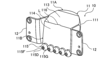
- FIG. 3 is a perspective view showing the lens unit 10 shown in FIG. 1 from the front side.
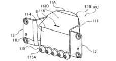
- FIG. 4 is a perspective view showing the lens unit 10 shown in FIG. 1 from the rear side.
- the lens body 11 is composed of an upper part 11A and a lower part 11B.
- An emission lens 111 is formed on the front side of the upper part 11A, and a primary reflection surface 112 is formed on the front side of the lower part 11B.
- the emission lens 111 is a lens such as a spherical lens or an aspherical lens that has positive power in the vertical direction and the width direction of the vehicle, and focuses the light emitted from the upper part 11A to the front side of the vehicle in the vertical direction and the width direction of the vehicle.
- the upper end of the primary reflection surface 112 is connected to the lower end of the emission lens 111, and the lower part of the primary reflection surface 112 faces the light source unit 21 in the fore-and-aft direction of the vehicle.
- the primary reflection surface 112 is inclined toward the front of the vehicle from the lower end to the upper end, and is curved in an arc shape that bulges toward the front of the vehicle, so that the light emitted from the light source unit 21 toward the front of the vehicle is reflected toward the upper side of the vehicle.
- a secondary reflection surface 113 is formed on the rear side of the upper portion 11A, and a rear reflection surface 114 and a light entrance portion 115 are formed on the rear side of the lower portion 11B.
- the secondary reflection surface 113 is a flat inclined surface located on the rear side of the output lens 111, inclined toward the front of the vehicle from the bottom end to the top end, and reflects the light reflected by the primary reflection surface 112 toward the front of the vehicle.
- the rear reflecting surface 114 is a flat inclined surface located on the rear side of the primary reflecting surface 112, and is inclined toward the front of the vehicle from the bottom end to the top end, and reflects the light reflected by the primary reflecting surface 112 toward the upper side of the vehicle.
- the top end of the rear reflecting surface 114 is connected to the bottom end of the secondary reflecting surface 113.
- a step 116 is formed on the boundary line L between the secondary reflecting surface 113 and the rear reflecting surface 114.
- the step 116 is provided to form a cutoff line of the low beam pattern, as will be described in detail later.
- the light entrance section 115 includes a number of lenses 115D arranged in the vehicle width direction. Each lens 115D is arranged opposite each light source 211. Each lens 115D is formed in a truncated cone shape and includes a diffusion section 115F on the central side and a light collecting section 115G on the outer periphery side. The optical axis of each light source 211 passes through the center of the diffusion section 115F.
- the diffusion section 115F is a convex or concave lens, and diffuses the light emitted from each light source 211 and passing through the diffusion section 115F in the vertical and horizontal directions of each lens 115D. The light diffused by the diffusion section 115F is irradiated in front of the vehicle as collimated light from the projection lens 2 with an expanded beam diameter.
- the focusing section 115G is a truncated cone-shaped inclined surface that gradually expands in diameter from the light source 211 side to the primary reflection surface 112 side, and focuses the diffuse light emitted from each light source 211 by total reflection.
- the light focused by the focusing section 115G is irradiated in front of the vehicle as collimated light from the projection lens 2 with a reduced beam diameter.
- FIG. 5 is a front view of the lens unit 10 shown in FIG. 1.
- FIG. 6 is a cross-sectional view taken along line 6-6 in FIG. 5.
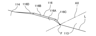
- FIG. 7 is an enlarged view of portion 7 in FIG. 6.
- FIG. 8 is an enlarged perspective view of the stepped portion 116 of the lens unit 10 shown in FIG. 4.
- FIG. 6 shows a vertical cross-section of the lens unit 10 at the center in the vehicle width direction.
- the primary reflective surface 112 has multiple reflective surfaces 112A, 112B, and 112C arranged in the vehicle width direction.
- Reflective surface 112A is provided corresponding to the central light source 211
- reflective surface 112B is provided corresponding to the second light source 211 from the center
- reflective surface 112C is provided corresponding to the outermost light source 211.
- the shapes of the reflective surfaces 112A, 112B, and 112C in the cross section of the lower portion 11B are arc-shaped.
- the shape of the central reflective surface 112A in the cross section of the lower portion 11B is a symmetrical arc convex toward the front of the vehicle, and this reflective surface 112A mainly reflects light from the central light source 211 toward the center of the lens unit 10 in the vehicle width direction.
- the shape of the second central reflective surface 112B in the cross section of the lower portion 11B is a circular arc convex diagonally outwardly forward, and this reflective surface 112B mainly reflects light from the second central light source 211 toward the center of the lens unit 10 in the vehicle width direction.
- the shape of the outermost reflective surface 112C in the cross section of the lower portion 11B is a circular arc convex diagonally outwardly forward, and this reflective surface 112C mainly reflects light from the outermost light source 211 toward the center of the lens unit 10 in the vehicle width direction.
- the reflecting surface 112A is an inclined surface that slopes from the bottom end to the top end toward the front of the vehicle.
- the reflecting surface 112A is also an arc-shaped curved surface that is convex diagonally downward toward the front.
- the reflecting surfaces 112B and 112C are also inclined surfaces that slope from the bottom end to the top end toward the front of the vehicle, and are also arc-shaped curved surfaces that are convex diagonally downward toward the front.
- Reflective surface 112A mainly reflects light from the central light source 221 toward the upper side of the vehicle.
- Reflective surface 112B mainly reflects light from the second light source 221 from the center toward the upper side of the vehicle.
- Reflective surface 112C mainly reflects light from the outermost light source 221 toward the upper side of the vehicle.
- the step 116 is formed in the center of the boundary (boundary line L) between the secondary reflection surface 113 and the rear reflection surface 114.
- the step 116 has surfaces 116A, 116B, 116C, and 116D.
- Surface 116A is a trapezoidal surface that protrudes from the upper end of the rear reflection surface 114 toward the upper side of the vehicle.
- Surface 116B is a horizontal surface located between the upper base of the trapezoidal surface 116A and the secondary reflection surface 113.
- Surface 116C is a slope located between one of the legs of the trapezoidal surface 116A (right side in the figure) and the secondary reflection surface 113.
- Surface 116D is a slope located between the other leg of the trapezoidal surface 116A (left side in the figure) and the secondary reflection surface 113.
- the optical axis AX of the projection lens 2 passes through the intersection of the boundary line L and surface 116C.
- the focal point F of the projection lens 2 is set at the position of the intersection of the boundary line L and surface 116C. Therefore, the boundary line L, surface 116C, and surface 116B function as a cutoff line forming portion that forms the cutoff line of the low beam pattern.
- the various parts of the lens unit 10 are arranged in the following order from the front of the vehicle: the emission surface of the emission lens 111, the upper end of the secondary reflection surface 113, the upper end of the primary reflection surface 112, the step portion 116, the lower end of the rear reflection surface 114, and the lens 115D. Note that the positional relationship between the upper end of the secondary reflection surface 113 and the upper end of the primary reflection surface 112 in the fore-and-aft direction of the vehicle may be reversed.
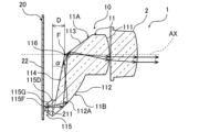
- FIG. 9 is a cross-sectional view showing the optical path of the vehicle headlamp 1 shown in FIG. 1.
- the light emitted from the light source 211 is incident on the lens 115D.
- the light that is incident on the lens 115D is diffused by the diffusion section 115F or focused by the focusing section 115G, and reaches the primary reflection surface 112.
- Light from lens 115D is reflected by primary reflective surface 112 toward the center of lens unit 10 in the vehicle width direction, and is mainly reflected toward the upper side of the vehicle in the vehicle vertical direction.
- the light reflected by primary reflective surface 112 reaches secondary reflective surface 113, rear reflective surface 114, or the boundary between these.
- primary reflective surface 112 is formed into an arc-shaped curved surface that is convex diagonally downward toward the front.
- the horizontal distance D between the vehicle front end of the lens 115D and the primary reflective surface 112, and the inclination angle ⁇ of the rear reflective surface 114 are set so that the angle of incidence of light on the primary reflective surface 112 is a predetermined angle (e.g., 39°) or greater.
- the horizontal distance D is, for example, 10 mm, and the inclination angle ⁇ is, for example, 12°.
- the inclination angle of secondary reflecting surface 113 (e.g., 36°) is set so that the angle of incidence of light on secondary reflecting surface 113 is a predetermined angle (e.g., 39°) or greater.
- the light passing through the exit lens 111 is focused by the positive power of the exit lens 111 in the vertical and width directions of the vehicle, and is emitted from the exit surface of the exit lens 111.
- the light emitted from the exit surface of the exit lens 111 is irradiated in front of the vehicle as collimated light by the projection lens 2.
- FIG. 10 is a diagram showing an example of a low beam pattern P L projected onto a virtual screen in front of a vehicle.
- This diagram shows an example of a low beam pattern P L projected by a vehicle headlamp 1 mounted on a vehicle traveling on the left side.
- line V-V indicates the vertical line of the screen
- line H-H indicates the horizontal line of the screen.
- the intersection of line V-V and line H-H corresponds to the reference position in the horizontal direction.
- a low beam pattern P L is formed in front of the vehicle by the light irradiated from the projection lens 2.
- a cutoff line CL is formed by a boundary line L between the secondary reflection surface 113 and the rear reflection surface 114.
- This cutoff line CL includes horizontal cutoff lines CL1 and CL3 and an oblique cutoff line CL2.
- the horizontal cutoff line CL1 is formed by a surface 116B of the step portion 116
- the oblique cutoff line CL2 is formed by a surface 116C of the step portion 116.
- the horizontal cutoff line CL3 is formed by the boundary line L.
- the light diffused by the diffusion portion 115F of the lens 115D irradiates an outer peripheral range PF of the low beam pattern PL
- the light condensed by the condensing portion 115G of the lens 115D irradiates a central range PG of the low beam pattern PL .
- the vehicle headlamp 1 of this embodiment includes the light source 211, the lens unit 10, and the projection lens 2 which is an aspheric lens.
- the light source 211 emits light toward the front of the vehicle
- the lens unit 10 transmits the light emitted from the light source 211
- the projection lens 2 irradiates the low beam pattern P L in front of the vehicle using the light transmitted through the lens unit 10.
- the lens unit 10 includes a lens 115D, a primary reflection surface 112, a secondary reflection surface 113, and an exit lens 111.
- the lens 115D diffuses or focuses the light emitted from the light source 211, and the primary reflection surface 112 reflects the light diffused or focused by the lens 115D in the vertical direction of the vehicle.
- the secondary reflection surface 113 reflects the light reflected by the primary reflection surface 112 toward the front of the vehicle, and the exit lens 111 focuses the light reflected by the secondary reflection surface 113 and outputs it to the projection lens 2.
- the projection lens 2 irradiates a low beam pattern P L in front of the vehicle using the light emitted from the exit lens 111.
- the focal point F of the projection lens 2 is set at a predetermined position (boundary line L) of the secondary reflection surface 113, and a step portion 116 for forming a cutoff line CL of the low beam pattern P L is formed at the predetermined position.
- This makes it possible to control the light distribution with the lens 115D, the primary reflection surface 112, the secondary reflection surface 113, and the output lens 111, and to irradiate the low beam pattern P L having the cutoff line CL, without providing a shade or reflector between the light source 211 and the projection lens 2. Therefore, it is possible to realize an efficient light distribution design and a reduction in the number of parts and part costs.
- the rear reflective surface 114 is provided on the lens unit 10 so as to face the primary reflective surface 112, and light reflected by the primary reflective surface 112 toward the rear of the vehicle is reflected by the rear reflective surface 114 toward the secondary reflective surface 113.
- the rear reflective surface 114 is inclined toward the front of the vehicle from the lens 115D side to the secondary reflective surface 113 side, and the angle of incidence of light to the rear reflective surface 114 is suppressed, so that total reflection can be caused by the rear reflective surface 114, and the amount of light reflected by the rear reflective surface 114 and reaching the secondary reflective surface 113 can be increased.
- FIG. 11 is a rear view showing a lens unit 10A provided in a vehicle headlamp 1A (see FIG. 12) according to another embodiment of the present invention.
- the lens unit 10A has a light entrance portion 1150.
- the configuration of the lens unit 10A is similar to that of the lens unit 10 of the above embodiment, except for the light entrance portion 1150. Note that the explanation of the above embodiment is used for the same configuration as the above embodiment.
- the light entrance section 1150 includes a number of lenses 115A, 115B, and 115C arranged in a line in the vehicle width direction.
- Lens 115A is arranged facing the central light source 211.
- the two lenses 115B are arranged so as to sandwich lens 115A on either side, and each lens 115B is arranged facing the second light source 211 from the center.
- the two lenses 115C are arranged so as to sandwich the three lenses 115A and 115B on either side, and each lens 115C is arranged facing the outermost light source 211.
- Each lens 115A, 115B, 115C is formed in a truncated cone shape and includes a diffusion section 115F on the central side and a focusing section 115G on the outer periphery.
- the configurations and functions of the diffusion section 115F and the focusing section 115G are the same as those in the above embodiment.
- Figure 12 is a cross-sectional view showing the optical path of a vehicle headlamp 1A equipped with the lens unit 10A shown in Figure 11.
- This figure shows a vertical cross section including the focal point F of the projection lens 2 and the center of the central lens 115A.
- light incident on lens 115A is diffused by diffusion section 115F and focused by focusing section 115G.
- light incident on lenses 115B and 115C is also diffused by diffusion section 115F and focused by focusing section 115G.
- FIG. 13 is a rear view showing the lenses 115A, 115B, and 115C of the lens unit 10A shown in FIG. 11.
- the areas of the diffusion sections 115F of the lenses 115A, 115B, and 115C are different from one another.
- the area of the diffusion section 115F of the central lens 115A is the smallest, and the area of the diffusion section 115F of the outermost lens 115C is the largest.
- the area of the diffusion sections 115F of the lenses 115A, 115B, and 115C gradually increases from the center in the vehicle width direction to the outside (as the distance from the position of the focal point F in the vehicle width direction increases).
- the area of the light collecting section 115G gradually decreases from the center in the vehicle width direction to the outside.
- the irradiation range (range P F in FIG. 10) of the collimated light diffused by the diffusion section 115F becomes wider, and the irradiation range (range P G in FIG. 10) of the collimated light focused by the focusing section 115G becomes narrower. Therefore, in this embodiment, the irradiation range of the collimated light diffused by the central lens 115A becomes narrower than the irradiation range of the collimated light diffused by the second lens 115B from the center.
- the irradiation range of the collimated light diffused by the second lens 115B from the center becomes narrower than the irradiation range of the collimated light diffused by the outermost lens 115C.
- the irradiation range of the collimated light focused by the central lens 115A becomes wider than the irradiation range of the collimated light focused by the second lens 115B from the center.
- the irradiation range of the collimated light collected by the second lens 115B from the center is wider than the irradiation range of the collimated light collected by the outermost lens 115C.
- the lenses 115A, 115B, and 115C include the diffusion section 115F through which the optical axis of each light source 211 passes, and the light collecting section 115G provided on the outer periphery of the diffusion section 115F.
- the diffusion section 115F diffuses the light emitted from the light source 211.
- the light collecting section 115G collects the light emitted from the light source 211.
- the areas of the diffusion portions 115F of the lenses 115A, 115B, and 115C are different from each other. This allows the range P G in which the light collected by the lenses 115A, 115B, and 115C of the low beam pattern P L is irradiated as collimated light and the range P F in which the light diffused by the lenses 115A, 115B, and 115C is irradiated as collimated light to be adjusted for each of the lenses 115A, 115B, and 115C. This increases the degree of freedom in light distribution design.
- the areas of the diffusion portions 115F of the central lens 115A and the second lens 115B from the center are different, and the areas of the diffusion portions 115F of the second lens 115B from the center and the outermost lens 115C are different, but this is not essential. It is only necessary that the area of the diffusion portion 115F of at least one of the plurality of lenses 115A, 115B, and 115C is different from the area of the diffusion portion 115F of the other lenses 115A, 115B, and 115C.
- FIG. 14 is a cross-sectional view showing a vehicle headlamp 1B according to another embodiment of the present invention.
- the vehicle headlamp 1B shown in this figure includes a colored material 6.
- the configuration of the vehicle headlamp 1B is similar to that of the vehicle headlamp 1 of the above embodiment, except that it includes a colored material 6. Note that the explanation of the above embodiment is used for the same configuration as the above embodiment.
- the colored material 6 is a material having a colored surface 61 arranged facing the secondary reflection surface 113, or a plate-like or block-like member.
- the colored surface 61 is arranged parallel to the secondary reflection surface 113 at a distance.
- the height from the bottom end to the top end of the colored surface 61 is equal to or greater than the dimension of the projection lens 2 in the vertical axis direction, and the colored surface 61 is arranged so as to overlap with the entire projection lens 2 when viewed from the front.
- the height from the bottom end to the top end of the colored surface 61 is equal to or greater than the dimension of the output lens 111 in the vertical axis direction, and the colored surface 61 is arranged so as to overlap with the entire output lens 111 when viewed from the front.
- the colored material 6 has the function of adjusting the color of the projection lens 2 when the light source 211 is off. If the colored surface 61 is black, the projection lens 2 will have a blackish color when the light source 211 is off. For example, the color of the projection lens 2 when the light source 211 is off is adjusted according to the color of the colored surface 61.
- the colored material 6 also has the function of absorbing light that passes through the secondary reflective surface 113 and leaves the lens unit 10. If the colored surface 61 is black, the amount of light absorbed by the colored surface 61 increases, and so on. The amount of light absorbed within the lens holder 3 that passes through the secondary reflective surface 113 is adjusted according to the color of the colored surface 61. The light that leaves the lens unit 10 within the lens holder 3 is absorbed, thereby reducing glare.
- the color of the colored material 6 is not limited to black, and any color may be selected. Also, the colored material 6 needs to be positioned away from the secondary reflection surface 113 so as not to impede the total reflection of light from the secondary reflection surface 113, but the size and shape may be selected as appropriate.
- FIG. 15 is an exploded perspective view showing a vehicle headlamp 1C according to another embodiment of the present invention from the front side.
- the vehicle headlamp 1C shown in this figure comprises a lens unit 10C, a light source board unit 20C, and a primary lens unit 30.
- the configuration of the vehicle headlamp 1C is similar to that of the vehicle headlamp 1 of the above embodiment, except for the configuration of part of the lens unit 10C, the fact that the light source unit 23 for high beams is provided on the light source board unit 20C, and the fact that it comprises a primary lens unit 30 for high beams. Note that the explanation of the above embodiment is used for the same configuration as the above embodiment.
- the high beam light source section 23 is mounted on the board 22.
- This high beam light source section 23 is arranged above the low beam light source section 21, and includes a plurality of light sources 231 arranged in the vehicle width direction.
- Each light source 231 is a light emitting element such as a light emitting diode. Note that each light source 231 may also be another light emitting body such as a laser.
- the light source unit 23 is disposed at the height of the optical axis AX of the projection lens 2, and emits light toward the front of the vehicle.
- the light emitted from the light source unit 23 enters the primary lens unit 30, where it is condensed, and reaches the lens unit 10C.
- the primary lens unit 30 is a one-piece molded product made of transparent resin and includes a lens body portion 31 and a bracket portion 32.
- the bracket portion 32 is a horizontally elongated member that extends in the vehicle width direction.
- the lens holder 3 and the base portion 4 are fastened together with the bracket portion 32 and the substrate 22 sandwiched between them.
- the lens body 31 extends downward from the longitudinal center of the bracket 32 and is disposed between the lower portion 11B of the lens unit 10C and the high beam light source 23.
- the optical axis AX of the projection lens 2 passes through this lens body 31.
- FIG. 16 is a perspective view showing the lens unit 10C shown in FIG. 15 from the rear side.
- FIG. 17 is a cross-sectional view showing the optical path of the vehicle headlamp 1C shown in FIG. 15.
- FIG. 18 is an enlarged view of portion 18 of FIG. 17.
- lens unit 10C has secondary reflective surface 113C.
- the boundary between secondary reflective surface 113C and rear reflective surface 114 is discontinuous, and the lower end E of secondary reflective surface 113C is located toward the rear of the vehicle relative to the upper end of rear reflective surface 114. Additionally, secondary reflective surface 113C extends below and toward the rear of the vehicle beyond step portion 116.
- the tip of the lens body 31 of the primary lens unit 30 is disposed between the light source 231 and the step 116.
- the optical axis AX of the projection lens 2 passes through the step 116, the tip of the lens body 31, and the light source 231.
- the focal point F of the projection lens 2 is set at the position of the step 116.
- a lens portion 311 is formed at the tip of the lens body portion 31, which is convex toward the light source 231 and has positive power in the vertical direction and the width direction of the vehicle.
- the light emitted from the light source 231 is condensed by the lens portion 311 and reaches the secondary reflection surface 113C.
- the lower end side of secondary reflection surface 113C extends further down and to the rear of the vehicle than step portion 116, and the lower end E of secondary reflection surface 113C is close to the tip of lens portion 311. Therefore, light that passes through lens portion 311 and reaches between step portion 116 and lower end E can be made to enter lens unit 10C from secondary reflection surface 113C.
- each light source 231 is collected by the lens portion 311 of the primary lens unit 30, passes through the secondary reflection surface 113C, and enters the lens unit 10C.
- the light is collected by the positive power of the emission lens 111 and reaches the projection lens 2, which irradiates the light in front of the vehicle as collimated light. This illuminates a high beam pattern in front of the vehicle.
- the vehicle headlamp 1C of this embodiment includes the light source 231 disposed so as to face the focal point F of the projection lens 2 in the front-rear direction of the vehicle.
- the light source 231 emits light toward the front of the vehicle
- the secondary reflection surface 113C transmits the light emitted from the light source 231
- the emission lens 111 collects the light transmitted through the secondary reflection surface 113C and emits it to the projection lens 2.
- the projection lens 2 irradiates a low beam pattern P L (see FIG.
- the vehicle headlamp 1C of this embodiment without providing a shade or reflector between the light sources 211, 231 and the projection lens 2, the light distribution can be controlled by the lens 115D, the primary reflective surface 112, the secondary reflective surface 113C, and the output lens 111, and a low beam pattern P L having a cut-off line CL and a high beam pattern can be irradiated.
- the vehicle headlamp 1C of this embodiment includes a lens portion 311 that focuses the light emitted from the light source 231. This increases the amount of light emitted from the light source 231 and entering the lens unit 10C, thereby increasing the luminosity of the high beam pattern.
- the light distribution pattern irradiated in front of the vehicle by the light emitted from light source 231 be a high beam pattern.
- the light distribution pattern may be a light distribution pattern for other functions such as daytime running lights.
- light source 211 and light source 231 may be turned on simultaneously, and a low beam pattern may be irradiated by the light emitted from light source 211 and the light emitted from light source 231.
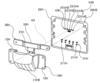
- the degree of freedom in designing the irradiation range and luminous intensity of the low beam pattern can be increased, for example, by making the irradiation range of the low beam pattern irradiated by the light emitted from light source 211 relatively wide and the luminous intensity of the low beam pattern irradiated by the light emitted from light source 231 relatively high.
- FIG. 19 is an exploded perspective view showing a vehicle headlamp 1H according to another embodiment of the present invention from the front side.
- FIG. 20 is a perspective view showing the vehicle headlamp 1H shown in FIG. 19 from the front side.
- the vehicle headlamp 1H shown in these figures is a high beam headlamp that irradiates a high beam pattern ahead of the vehicle.
- the vehicle headlamp 1H includes a projection lens 2H, a lens holder 3H, a lens unit 10H, a light source board unit 20H, a base portion 4H, and a heat dissipation member 5H.
- the projection lens 2H is an aspheric lens, and works together with the lens unit 10H to collimate the light emitted from the light source portion 21H of the light source board unit 20H and project a high beam pattern forward of the vehicle.
- a flange portion 2HF is formed on the peripheral portion of the rear side of the projection lens 2H.
- the direction parallel to the optical axis AX of the projection lens 2H is defined as the vehicle longitudinal direction
- the vertical direction perpendicular to the optical axis AX of the projection lens 2H is defined as the vehicle vertical direction
- the horizontal direction perpendicular to the optical axis AX of the projection lens 2H is defined as the vehicle width direction.
- the lens holder 3H is a frame with rectangular openings formed on the front and rear sides.
- a number of locking claws 30HB are provided on the periphery of the opening 30HA on the front side of the lens holder 3H.
- the projection lens 2H is attached to the front side of the lens holder 3H so as to cover the opening 30HA.
- the multiple locking claws 30HB lock onto the flange portion 2HF of the projection lens 2H, thereby fixing the projection lens 2H to the front side of the lens holder 3H.
- the base portion 4H is attached to the rear surface of the lens holder 3H so as to cover the opening.
- the lens holder 3H and the base portion 4H are fastened together with fastening members such as bolts and nuts.
- the heat dissipation member 5H is composed of multiple fins 51H arranged in parallel. These multiple fins 51H are attached to the back surface of the base portion 4H. The base portion 4H and the heat dissipation member 5H dissipate the heat generated by the light source portion 21H to the outside.
- the light source board unit 20H includes a light source section 21H and a board 22H on which the light source section 21H is mounted.
- the light source section 21H includes a plurality of light sources 211H arranged in a line in the vehicle width direction on the front surface of the board 22H.
- Each light source 211H is a light-emitting element such as a light-emitting diode. Note that each light source 211H may also be another light-emitting body such as a laser.
- the light source unit 21H is disposed below the optical axis AX of the projection lens 2H and emits light toward the front of the vehicle.
- the light emitted from the light source unit 21H enters the lens unit 10H, is totally reflected by a reflecting surface formed on the lens unit 10H, and is emitted from the lens unit 10H toward the front of the vehicle, and reaches the projection lens 2H.
- the lens unit 10H is disposed between the light source board unit 20H and the projection lens 2H.
- the lens unit 10H is a one-piece molded product made of transparent resin and includes a lens body portion 11H and a pair of bracket portions 12H.
- the pair of bracket portions 12H are arranged to sandwich the lens body portion 11H in the vehicle width direction. With the pair of bracket portions 12H and the board 22H sandwiched between the lens holder 3H and the base portion 4H, the lens holder 3H and the base portion 4H are fastened to each other.
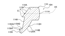
- FIG. 21 is a perspective view showing the lens unit 10H shown in FIG. 19 from the front side.
- FIG. 22 is a perspective view showing the lens unit 10H shown in FIG. 19 from the rear side.
- the lens body 11H is composed of an upper part 11HA and a lower part 11HB.
- An emission lens 111H is formed on the front side of the upper part 11HA, and a primary reflection surface 112H is formed on the front side of the lower part 11HB.
- the emission lens 111H is a lens such as a spherical lens or an aspherical lens that has positive power in the vertical and lateral directions of the vehicle, and focuses the light emitted from the upper part 11HA to the front side of the vehicle in the vertical and lateral directions of the vehicle.
- the upper end of the primary reflection surface 112H is connected to the lower end of the emission lens 111H, and the lower part of the primary reflection surface 112H faces the light source unit 21H in the front-to-rear direction of the vehicle.
- the primary reflection surface 112H is inclined toward the front of the vehicle from the lower end to the upper end, and is curved in an arc shape that bulges toward the front of the vehicle, so that the light emitted from the light source unit 21H toward the front of the vehicle is reflected toward the upper side of the vehicle.
- a secondary reflective surface 113H is formed on the rear side of the upper portion 11HA, and a rear reflective surface 114H and a light entrance portion 115H are formed on the rear side of the lower portion 11HB.
- the secondary reflective surface 113H is a flat inclined surface located on the rear side of the output lens 111H, inclined toward the front of the vehicle from the bottom end to the top end, and reflects the light reflected by the primary reflective surface 112H toward the front of the vehicle.
- the rear reflecting surface 114H is a flat inclined surface located on the rear side of the primary reflecting surface 112H, inclined toward the front of the vehicle from the bottom end to the top end, and reflects the light reflected by the primary reflecting surface 112H toward the upper side of the vehicle.
- the boundary between the secondary reflecting surface 113H and the rear reflecting surface 114H is discontinuous, and the bottom end E of the secondary reflecting surface 113H is located toward the rear of the vehicle relative to the top end of the rear reflecting surface 114H.
- the bottom end E of the secondary reflecting surface 113H and the top end of the rear reflecting surface 114H are at the same height.
- the light entrance portion 115H has a plurality of lenses 115HD arranged in the vehicle width direction. Each lens 115HD is arranged opposite each light source 211H. Each lens 115HD is formed in a truncated cone shape and has a diffusion portion 115HF on the central side and a light collecting portion 115HG on the outer periphery side. The optical axis of the light source 211H passes through the center of the diffusion portion 115HF.
- the diffusion portion 115HF is a convex or concave lens, and diffuses the light emitted from each light source 211H and passing through the diffusion portion 115HF in the vertical and horizontal directions of each lens 115HD. The light diffused by the diffusion portion 115HF is irradiated in front of the vehicle as collimated light from the projection lens 2H with an expanded beam diameter.
- the focusing section 115HG is a truncated cone-shaped inclined surface that gradually expands in diameter from the light source 211H side to the primary reflection surface 112H side, and focuses the diffuse light emitted from each light source 211H by total reflection.
- the light focused by the focusing section 115HG is irradiated in front of the vehicle as collimated light from the projection lens 2H with a reduced beam diameter.
- FIG. 23 is a front view showing the lens unit 10H shown in FIG. 19.
- FIG. 24 is a cross-sectional view taken along line 24-24 of FIG. 23.
- the primary reflective surface 112H has a plurality of reflective surfaces 112HA, 112HB, 112HC arranged in the vehicle width direction.
- the reflective surface 112HA is provided corresponding to the central light source 211H
- the reflective surface 112HB is provided corresponding to the second light source 211H from the center
- the reflective surface 112HC is provided corresponding to the outermost light source 211H.
- the shapes of the reflective surfaces 112HA, 112HB, 112HC in the cross section of the lower portion 11HB are arc-shaped.
- the shape of the central reflective surface 112HA in the cross section of the lower portion 11HB is a symmetrical arc convex toward the front of the vehicle, and this reflective surface 112HA mainly reflects light from the central light source 211H toward the center of the lens unit 10H in the vehicle width direction.
- the shape of the second central reflective surface 112HB in the cross section of the lower portion 11HB is a circular arc convex diagonally outwardly forward, and this reflective surface 112HB mainly reflects light from the second central light source 211H toward the center of the lens unit 10H in the vehicle width direction.
- the shape of the outermost reflective surface 112HC in the cross section of the lower portion 11HB is a circular arc convex diagonally outwardly forward, and this reflective surface 112HC mainly reflects light from the outermost light source 211H toward the center of the lens unit 10H in the vehicle width direction.
- the reflecting surface 112HA is an inclined surface that slopes from the bottom end to the top end toward the front of the vehicle.
- the reflecting surface 112HA is also an arc-shaped curved surface that is convex diagonally downward toward the front.
- the reflecting surfaces 112HB, 112HC are also inclined surfaces that slope from the bottom end to the top end toward the front of the vehicle, and are also arc-shaped curved surfaces that are convex diagonally downward toward the front.
- Reflective surface 112HA mainly reflects light from the central light source 221H toward the upper side of the vehicle.
- Reflective surface 112HB mainly reflects light from the second light source 221H from the center toward the upper side of the vehicle.
- Reflective surface 112HC mainly reflects light from the outermost light source 221H toward the upper side of the vehicle.
- the optical axis AX of the projection lens 2H passes through a predetermined position on the secondary reflection surface 113H.
- This predetermined position is located between the center of the secondary reflection surface 113H in the vehicle width direction and the center of the vehicle in the vertical direction and the bottom end E.
- the focal point F of the projection lens 2H is set at the above-mentioned predetermined position where the secondary reflection surface 113H and the optical axis AX intersect.
- the parts of lens unit 10H are arranged in the following order from the front of the vehicle: the emission surface of emission lens 111H, the upper end of primary reflective surface 112H, the upper end of secondary reflective surface 113H, the upper end of rear reflective surface 114H, the lower end E of secondary reflective surface 113H, the lower end of rear reflective surface 114H, and lens 115HD.
- the positional relationship between the upper end of primary reflective surface 112H and the upper end of secondary reflective surface 113H in the fore-and-aft direction of the vehicle may be reversed.
- the positional relationship between the lower end E of secondary reflective surface 113H and the lower end of rear reflective surface 114H in the fore-and-aft direction of the vehicle may also be reversed.
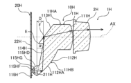
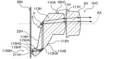
- Figure 25 is a cross-sectional view showing the optical path of the vehicle headlamp 1H shown in Figure 19.
- light emitted from the light source 211H is incident on the lens 115HD.
- the light that is incident on the lens 115HD is diffused by the diffusion section 115HF or focused by the focusing section 115HG, and reaches the primary reflection surface 112H.
- Light from lens 115HD is reflected by primary reflective surface 112H toward the center of lens unit 10H in the vehicle width direction, and is mainly reflected toward the upper side of the vehicle in the vehicle vertical direction.
- the light reflected by primary reflective surface 112H reaches secondary reflective surface 113H or rear reflective surface 114H.
- primary reflective surface 112H is formed into an arc-shaped curved surface that is convex diagonally downward toward the front.
- the horizontal distance D between the vehicle front end of lens 115HD and primary reflective surface 112H, and the inclination angle ⁇ of rear reflective surface 114H are set so that the angle of incidence of light on primary reflective surface 112H is a predetermined angle (e.g., 39°) or greater.
- the horizontal distance D is, for example, 10 mm, and the inclination angle ⁇ is, for example, 12°.
- the light reflected by primary reflecting surface 112H toward secondary reflecting surface 113H is reflected by secondary reflecting surface 113H toward the front of the vehicle and reaches exit lens 111H.
- Light reflected by primary reflecting surface 112H toward rear reflecting surface 114H is reflected by rear reflecting surface 114H toward secondary reflecting surface 113H, and is reflected by secondary reflecting surface 113H toward the front of the vehicle and reaches exit lens 111H.
- the inclination angle of secondary reflecting surface 113H (e.g., 50°) is set so that the angle of incidence of light on secondary reflecting surface 113H is a predetermined angle (e.g., 39°) or more.
- the light passing through the exit lens 111H is focused by the positive power of the exit lens 111H in the vertical and width directions of the vehicle, and is emitted from the exit surface of the exit lens 111H.
- the light emitted from the exit surface of the exit lens 111H is irradiated in front of the vehicle as collimated light by the projection lens 2H.
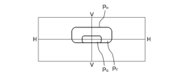
- 26 is a diagram showing an example of a high beam pattern P H projected onto a virtual screen in front of a vehicle.
- line V-V indicates the vertical line of the screen
- line H-H indicates the horizontal line of the screen. Furthermore, the intersection of line V-V and line H-H corresponds to the reference position in the horizontal direction.
- a high beam pattern P H is formed in front of the vehicle by light emitted from the projection lens 2H.
- the light diffused by the diffusion portion 115HF of the lens 115HD irradiates an outer peripheral range P F of the high beam pattern P H
- the light collected by the light collecting portion 115HG of the lens 115HD irradiates a central range P G of the high beam pattern P H.
- the vehicle headlamp 1H of this embodiment includes the light source 211H, the lens unit 10H, and the projection lens 2H which is an aspheric lens.
- the light source 211H emits light toward the front of the vehicle
- the lens unit 10H transmits the light emitted from the light source 211H
- the projection lens 2H irradiates the high beam pattern P H toward the front of the vehicle using the light transmitted through the lens unit 10H.
- the lens unit 10H includes a plurality of lenses 115HD, a primary reflection surface 112H, a secondary reflection surface 113H, and an exit lens 111H.
- the lens 115HD diffuses or focuses the light emitted from the light source 211H
- the primary reflection surface 112H reflects the light diffused or focused by the lens 115HD toward the vehicle vertical direction.
- the secondary reflection surface 113H reflects the light reflected by the primary reflection surface 112H toward the vehicle front
- the exit lens 111H focuses the light reflected by the secondary reflection surface 113H and emits it to the projection lens 2H.
- the projection lens 2H irradiates a high beam pattern P H forward of the vehicle using the light emitted from the exit lens 111H.
- the focal point F of the projection lens 2H is set at a predetermined position of the secondary reflection surface 113H.
- the light distribution can be controlled by the lens 115HD, the primary reflection surface 112H, the secondary reflection surface 113H, and the output lens 111H, and collimated light can be output from the projection lens 2H to irradiate the high beam pattern P H. Therefore, an efficient light distribution design and a reduction in the number of parts and part costs can be realized.
- the rear reflective surface 114H is provided on the lens unit 10H so as to face the primary reflective surface 112H, and light reflected toward the rear of the vehicle by the primary reflective surface 112H is reflected toward the secondary reflective surface 113H by the rear reflective surface 114H. This increases the amount of light reflected by the primary reflective surface 112H and reaching the secondary reflective surface 113H.
- the rear reflective surface 114H is inclined toward the front of the vehicle from the lens 115HD side to the secondary reflective surface 113H side, and the angle of incidence of light to the rear reflective surface 114H is suppressed, so that total reflection can be caused by the rear reflective surface 114H, and the amount of light reflected by the rear reflective surface 114H and reaching the secondary reflective surface 113H can be increased.
- the lower end E of the secondary reflection surface 113H is located on the vehicle rear side and the vehicle lower side of the focal point F of the projection lens 2H, and the secondary reflection surface 113H extends to the vehicle rear side and the vehicle lower side of the focal point F of the projection lens 2H.
- the focal point F optical axis AX
- the amount of light reflected by the primary reflection surface 112H and reaching the secondary reflection surface 113H can be increased, and the amount of light irradiated as the high beam pattern P H can be increased.
- FIG. 27 is an exploded perspective view showing a vehicle headlamp 1HA according to another embodiment of the present invention, viewed from the front.
- the vehicle headlamp 1HA shown in this figure comprises a lens unit 10H, a light source board unit 20HA, and a primary lens unit 30H.
- the configuration of the vehicle headlamp 1HA is similar to that of the vehicle headlamp 1H of the above embodiment, except that the light source board unit 20HA is provided with a light source section 23H, and that the vehicle headlamp 1HA comprises a primary lens unit 30H. Note that the explanation of the above embodiment is used for the same configuration as the above embodiment.
- the light source section 23H is mounted on the board 22H.
- This light source section 23H is disposed on the vehicle upper side of the light source section 21H, and includes one or more light sources 231H.
- the light source 231H is a light-emitting element such as a light-emitting diode. Note that the light source 231H may be another light-emitting body such as a laser.
- the light source unit 23H is disposed at the height of the optical axis AX of the projection lens 2H, and emits light toward the front of the vehicle.
- the light emitted from the light source 231H enters the primary lens unit 30H, is collected by the primary lens unit 30H, and reaches the lens unit 10H.
- the luminous intensity of the light emitted from the light source 231H of the light source unit 23H is set to be higher than the luminous intensity of the light emitted from each light source 211H of the light source unit 21H.
- the irradiation range of the light emitted from each light source 211H of the light source unit 21H is set to be wider than the irradiation range of the light emitted from the light source 231H of the light source unit 23H. For this reason, the entire area of the high beam pattern P H (see FIG.
- the primary lens unit 30H is a one-piece molded product made of transparent resin and includes a lens body portion 31H and a bracket portion 32H.
- the bracket portion 32H is a horizontally elongated member that extends in the vehicle width direction.
- the lens holder 3H and the base portion 4H are fastened together with the bracket portion 32H and the substrate 22H sandwiched between them.
- the lens body 31H extends downward from the longitudinal center of the bracket 32H and is disposed between the lens body 11H of the lens unit 10H and the light source 23H.
- the optical axis AX of the projection lens 2H passes through this lens body 31H.
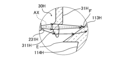
- Figure 28 is a cross-sectional view showing the optical path of the vehicle headlamp 1HA shown in Figure 27.
- Figure 29 is an enlarged view of part 29 of Figure 28.
- the tip of the lens body 31H of the primary lens unit 30H is disposed between the light source 231H and the secondary reflection surface 113H.
- the optical axis AX of the projection lens 2H passes through the secondary reflection surface 113H, the tip of the lens body 31H, and the light source 231H.
- the focal point F of the projection lens 2H is set on the secondary reflection surface 113H, and the tip of the lens body 31H is disposed between the light source 231H and the focal point F.
- a lens portion 311H is formed at the tip of the lens body portion 31H, which is convex toward the light source 231H and has positive power in the vertical direction and the width direction of the vehicle.
- the light emitted from the light source 231H is condensed by the lens portion 311H and reaches the secondary reflection surface 113H.
- the lower end side of the secondary reflection surface 113H extends rearward and downward from the focal point F, and the lower end E of the secondary reflection surface 113H is close to the lens portion 311H. Therefore, light that passes through the lens portion 311H and reaches between the focal point F and the lower end E can be made to enter the lens unit 10H from the secondary reflection surface 113H.
- the components of vehicle headlamp 1HA are arranged in the following order from the front of the vehicle: projection lens 2H, the emission surface of emission lens 111H, the upper end of primary reflective surface 112H, the upper end of secondary reflective surface 113H, the upper end of rear reflective surface 114H, the lower end E of secondary reflective surface 113H, the lower end of rear reflective surface 114H, lens body portion 31H of primary lens unit 30H, and light source 231H.
- the positions of light source 211H and light source 231H in the vehicle longitudinal direction are the same. Note that the positional relationship between the upper end of primary reflective surface 112H and the upper end of secondary reflective surface 113H in the vehicle longitudinal direction may be reversed. Also, the positional relationship between the lower end E of secondary reflective surface 113H and the lower end of rear reflective surface 114H in the vehicle longitudinal direction may be reversed.
- light emitted from light source 231H is collected by lens portion 311H of primary lens unit 30H, passes through secondary reflection surface 113H, and enters lens unit 10H.
- the light is collected by the positive power of output lens 111H and reaches projection lens 2H, where it is irradiated in front of the vehicle as collimated light. This illuminates an additional light distribution pattern in front of the vehicle.
- the vehicle headlamp 1HA of this embodiment includes the light source 231H arranged to face the focal point F of the projection lens 2H in the front-rear direction of the vehicle.
- the light source 231H emits light toward the front of the vehicle
- the secondary reflection surface 113H transmits the light emitted from the light source 231H
- the emission lens 111H collects the light that has transmitted through the secondary reflection surface 113H and emits it to the projection lens 2H.
- the projection lens 2H irradiates a high beam pattern P H (see FIG.
- the vehicle headlamp 1HA of this embodiment includes a lens portion 311H that collects the light emitted from the light source 231H. This makes it possible to increase the amount of light emitted from the light source 231H and incident on the lens unit 10H, thereby increasing the luminous intensity of the center portion of the high beam pattern P H.
- the lower end E of the secondary reflection surface 113H is located rearward and below the vehicle relative to the focal point F of the projection lens 2H and is close to the lens portion 311H, thereby making it possible to increase the amount of light emitted from the light source 231H and incident on the lens unit 10H.
- the light source unit 21H and the light source unit 23H are arranged at a distance from each other, which allows the heat generating portion to be dispersed. This eliminates the need to enlarge the substrate 22H and the heat dissipation member 5H for dissipating heat from the light source units 21H and 23H, making it possible to reduce the size of the substrate 22H and the heat dissipation member 5H and thereby reduce costs.
- Figure 30 is an exploded perspective view showing a portion of a vehicle headlamp 1HB according to another embodiment of the present invention, viewed from the front.
- the vehicle headlamp 1HB of this embodiment includes a light source board unit 20HB.
- the configuration of the vehicle headlamp 1HB is similar to that of the vehicle headlamp 1HA of the above embodiment, except that the configuration of the light source section 23H of the light source board unit 20HB is different. Note that the explanation of the above embodiment is used for the same configuration as the above embodiment.
- the light source section 23H includes a plurality of light sources 231HA, 231HB arranged side by side in the vehicle width direction.
- the central light source 231HA emits light corresponding to an additional light distribution pattern for increasing the luminous intensity of the center of the high beam pattern P H (see Fig. 26).
- the outer light sources 231HA, 231HB (for example, four as shown in the figure) are light-emitting elements such as light-emitting diodes.
- Each light source 231HA, 231HB may be another light-emitting body such as a laser.
- Fig. 31 is a cross-sectional view showing the optical path of the vehicle headlamp 1HB shown in Fig. 30.
- the light emitted from the central light source 231HA of the light source section 23H is collected by the lens section 311H of the primary lens unit 30H, passes through the secondary reflection surface 113H, and enters the lens unit 10H.
- the light is collected by the positive power of the emission lens 111H and reaches the projection lens 2H, and is irradiated as collimated light by the projection lens 2H to the front of the vehicle.
- an additional light distribution pattern for increasing the luminous intensity of the center of the high beam pattern P H is irradiated to the front of the vehicle.
- the light emitted from the light source 231HB outside the light source section 23H is collected by the lens section 311H of the primary lens unit 30H, passes through the secondary reflection surface 113H, and enters the lens unit 10H.
- the light is collected by the positive power of the emission lens 111H and reaches the projection lens 2H, which irradiates the front of the vehicle as collimated light. This causes the light distribution pattern of other functions, such as daylight, to be illuminated in front of the vehicle.
- the light emitted from the light source 231HB of the light source section 23H is used to illuminate the light distribution pattern of daylight, when the light source 231HB is turned on, the light sources 211H of the light source section 21H and the light source 231HA of the light source section 23H are turned off.
- the light source 231HA of the light source unit 23H is turned on simultaneously with each light source 211H of the light source unit 21H, or is turned on when each light source 211H of the light source unit 21H is turned off.
- the projection lens 2H irradiates an additional light distribution pattern that overlaps with the center of the high beam pattern P H to the front of the vehicle by the light emitted from the light source 231HA.
- the projection lens 2H irradiates a light distribution pattern such as daylight, which has a different function from the high beam pattern P H, to the front of the vehicle by the light emitted from the light source 231HB.
- a light distribution pattern such as daylight, which has a different function from the high beam pattern P H.
- both light sources 231HA and 231HB may be turned on to irradiate the additional light distribution pattern
- both light sources 231HA and 231HB may be turned on to irradiate the light distribution pattern of the other function.
- FIG. 32 is a rear view showing lens unit 10HC provided in vehicle headlamp 1HC (see FIG. 33) according to another embodiment of the present invention.
- lens unit 10HC has a light entrance portion 1150H.
- the configuration of lens unit 10HC is similar to that of lens unit 10H in the above embodiment, except for light entrance portion 1150H. Note that the explanation of the above embodiment is used for the same configuration as in the above embodiment.
- the light entrance portion 1150H has a number of lenses 115HA, 115HB, 115HC arranged in a line in the vehicle width direction.
- the lens 115HA is arranged facing the central light source 221H.
- the two lenses 115HB are arranged so as to sandwich the lens 115HA on either side, and each lens 115HB is arranged facing the second light source 221H from the center.
- the two lenses 115HC are arranged so as to sandwich the three lenses 115HA, 115HB on either side, and each lens 115HC is arranged facing the outermost light source 221H.
- Each lens 115HA, 115HB, 115HC is formed in a truncated cone shape and has a diffusion section 115HF in the center and a focusing section 115HG on the outer periphery.
- the configurations and functions of the diffusion section 115HF and the focusing section 115HG are the same as those in the above embodiment.
- Figure 33 is a cross-sectional view showing the optical path of vehicle headlamp 1HC equipped with lens unit 10HC shown in Figure 32.
- This figure shows a vertical cross section including focal point F of projection lens 2H and the center of central lens 115HA.
- light incident on lens 115HA is diffused by diffusion section 115HF and focused by focusing section 115HG.
- light incident on lenses 115HB and 115HC is also diffused by diffusion section 115HF and focused by focusing section 115HG.
- FIG. 34 is a rear view showing the lenses 115HA, 115HB, and 115HC of the lens unit 10HC shown in FIG. 32.
- the areas of the diffusion portions 115HF of the lenses 115HA, 115HB, and 115HC are different from one another.
- the area of the diffusion portion 115HF of the central lens 115HA is the smallest, and the area of the diffusion portion 115HF of the outermost lens 115HC is the largest.
- the area of the diffusion portions 115HF of the lenses 115HA, 115HB, and 115HC gradually increases from the center in the vehicle width direction to the outside (as the distance from the position of the focal point F in the vehicle width direction increases).
- the area of the light collecting portion 115HG gradually decreases from the center in the vehicle width direction to the outside.
- the irradiation range of the collimated light diffused by the second lens 115HB from the center becomes narrower than the irradiation range of the collimated light diffused by the outermost lens 115HC.
- the irradiation range of the collimated light collected by the central lens 115HA becomes wider than the irradiation range of the collimated light collected by the second lens 115HB from the center.
- the irradiation range of the collimated light focused by the second lens 115HB from the center is wider than the irradiation range of the collimated light focused by the outermost lens 115HC.
- the lenses 115HA, 115HB, and 115HC include the diffusion portion 115HF through which the optical axis of the light source 211H passes, and the light collecting portion 115HG provided on the outer periphery of the diffusion portion 115HF.
- the diffusion portion 115HF diffuses the light emitted from the light source 211H.
- the light collecting portion 115HG collects the light emitted from the light source 211H.
- the areas of the diffusion portion 115HF of the lenses 15HA, 15HB, and 15HC are different from each other. This allows the range P G in which the light collected by the lenses 115HA, 115HB, and 115HC of the high beam pattern P H is irradiated as collimated light and the range P F in which the light diffused by the lenses 115HA, 115HB, and 115HC is irradiated as collimated light to be adjusted for each lens 115HA, 115HB, and 115HC. This increases the degree of freedom in light distribution design.
- the areas of the diffusion portion 115HF of the central lens 115HA and the second lens 115HB from the center are different, and the areas of the diffusion portion 115HF of the second lens 115HB from the center and the outermost lens 115HC are different, but this is not essential. It is only necessary that the area of the diffusion portion 115HF of at least one of the plurality of lenses 115HA, 115HB, and 115HC is different from the area of the diffusion portion 115HF of the other lenses 115HA, 115HB, and 115HC.
- the light source unit 21 is disposed below the projection lens 2, and the light emitted from the light source unit 21 is reflected toward the upper side of the vehicle by the primary reflection surface 112.
- the light source unit 21 may be disposed above the projection lens 2, and the light emitted from the light source unit 21 may be reflected toward the lower side of the vehicle by the primary reflection surface 112.
- the light source unit 21H is disposed below the projection lens 2H, and the light emitted from the light source unit 21H is reflected toward the upper side of the vehicle by the primary reflection surface 112H.
- this is not essential, and the light source unit 21H may be disposed above the vehicle by the projection lens 2H, and the light emitted from the light source unit 21H may be reflected toward the lower side of the vehicle by the primary reflection surface 112H.
- the central parts of the lenses 115A, 115B, 115C, and 115D are the diffusion parts 115F, and the outer parts of the lenses 115A, 115B, 115C, and 115D are the light collecting parts 115G.
- the central parts of the lenses 115A, 115B, 115C, and 115D only need to be parts where the light emitted from the light source 211 passes through the primary reflection surface 112 side and diffuses the light relatively compared to the outer parts, and it is not essential that the light emitted from these parts is diffused light.
- the outer parts of the lenses 115A, 115B, 115C, and 115D only need to be parts (reflection surfaces) where the light emitted from the light source 211 is reflected toward the primary reflection surface 112 side and concentrates the light relatively compared to the central parts, and it is not essential that the light reflected at these parts is concentrated.
- the central portions of lenses 115HA, 115HB, 115HC, and 115HD are diffusion portions 115HF, and the outer portions of lenses 115HA, 115HB, 115HC, and 115HD are light-concentrating portions 115HG.
- the central portions of lenses 115HA, 115HB, 115HC, and 115HD only need to be portions where light emitted from light source 211H passes through primary reflection surface 112H and diffuses the light relatively compared to the outer portions, and it is not essential that the light emitted from these portions be diffused light.
- lenses 115HA, 115HB, 115HC, and 115HD need only be parts (reflective surfaces) that reflect the light emitted from light source 211H toward primary reflection surface 112H and concentrate the light relatively compared to the central part, and it is not essential that the light reflected at these parts is concentrated.
Landscapes
- Engineering & Computer Science (AREA)
- General Engineering & Computer Science (AREA)
- Physics & Mathematics (AREA)
- Microelectronics & Electronic Packaging (AREA)
- Optics & Photonics (AREA)
- Non-Portable Lighting Devices Or Systems Thereof (AREA)
Abstract
効率良く配光設計すること、及び部品点数や部品コストを抑えることを可能にする車両用前照灯を提供する。 車両用前照灯(1)は、車両前方側に光を出射する光源(211)と、光源(211)から出射された光が透過するレンズユニット(10)と、レンズユニット(10)を透過した光により車両前方に配光パターンを照射する投影レンズ(2)とを備え、レンズユニット(10)は、光源(211)から出射された光が入射する光入射部(115)に設けられたレンズ(115D)と、レンズ(115D)を通過した光を車両上下方向に反射する一次反射面(112)と、一次反射面(112)で反射された光を車両前方側に反射する二次反射面(113)と、二次反射面(113)で反射された光が出射する光出射部に設けられた出射レンズ(111)とを備え、投影レンズ(2)の焦点(F)が、二次反射面(113)の所定位置に設定されている。
Description
本発明は、車両用前照灯に関する。
車両用照明灯具として、発光素子と、発光素子からの光が透過する透光ブロックとを備え、透光ブロックを透過する光を反射する第1反射面及び第2反射面が透光ブロックの表面に形成されているものが知られている(例えば、特許文献1参照)。特許文献1に記載の車両用照明灯具では、発光素子が、灯具前後方向に延びる光軸上に配置され、第1反射面が、発光素子からの光を上記光軸の径方向外方へ向けて反射し、第2反射面が、第1反射面で反射した光を前方へ向けて反射させる。特許文献1に記載の車両用照明灯具は、ハイビーム用のヘッドランプの一部として構成されている。
ロービームパターンとハイビームパターンとを形成する車両用前照灯が知られている(例えば、特許文献2参照)。特許文献2に記載の車両用前照灯は、ロービーム用の第1光源と、ハイビーム用の第2光源と、第1反射面、第2反射面、及び第3反射面を備えるリフレクタと、投影レンズとを備える。特許文献2に記載の車両用前照灯では、第2光源が第1光源の上方に配され、第1反射面が、第1光源からの光を上方に反射し、第2反射面が、第1反射面からの光を前方に反射し、第3反射面が、第2反射面からの光を前方に反射する。投影レンズは、第1光源から出射されたロービーム用の光と第2光源から出射されたハイビーム用の光とを前方に照射する。特許文献2に記載の車両用前照灯では、第2反射面と第3反射面との境界にカットオフラインを形成するためのカットオフ形成部が設けられている。
特許文献1に記載の車両用照明灯具を、ロービーム用のヘッドランプの一部として構成する場合には、カットオフラインを形成するためのシェードを設ける必要があり、部品点数や部品コストが増加する。また、特許文献1に記載の車両用照明灯具では、透光ブロックを透過する光を第1反射面と第2反射面とによりコリメートすることを目的として配光設計が行われているため、配光設計の制約が大きい。また、特許文献2に記載の車両用前照灯は、コリメータレンズ等のレンズを設ける場合、リフレクタに加えてレンズが必要となり、部品点数や部品コストが増加する。
本発明は、上記事情に鑑み、効率良く配光設計すること、及び部品点数や部品コストを抑えることを可能にする車両用前照灯を提供することを目的とする。
本発明に係る車両用前照灯は、車両前方側に光を出射する第1光源と、前記第1光源から出射された光が透過するレンズユニットと、前記レンズユニットを透過した光により車両前方に配光パターンを照射する非球面レンズとを備え、前記レンズユニットは、前記第1光源から出射された光が入射する光入射部に設けられた第1レンズと、前記第1レンズを通過した光を車両上下方向に反射する一次反射面と、前記一次反射面で反射された光を車両前方側に反射する二次反射面と、前記二次反射面で反射された光が出射する光出射部に設けられた第2レンズとを備え、前記非球面レンズの焦点が、前記二次反射面の所定位置に設定されている。
本発明によれば、効率良く配光設計すること、及び部品点数や部品コストを抑えることが可能になる。
以下、本発明を好適な実施形態に沿って説明する。なお、本発明は以下に示す実施形態に限られるものではなく、本発明の趣旨を逸脱しない範囲において適宜変更可能である。また、以下に示す実施形態においては、一部構成の図示や説明を省略している箇所があるが、省略された技術の詳細については、以下に説明する内容と矛盾が発生しない範囲内において、適宜公知又は周知の技術が適用される。
図1は、本発明の一実施形態に係る車両用前照灯1を正面側から示す分解斜視図である。また、図2は、図1に示す車両用前照灯1を正面側から示す斜視図である。これらの図に示す車両用前照灯1は、ロービームパターンを車両前方に照射するロービーム用の前照灯である。
図1に示すように、車両用前照灯1は、投影レンズ2と、レンズホルダ3と、レンズユニット10と、光源基板ユニット20と、ベース部4と、放熱部材5とを備える。投影レンズ2は、非球面レンズであり、レンズユニット10との共働により、光源基板ユニット20の光源部21から出射された光をコリメートし、車両前方にロービームパターンを照射する。この投影レンズ2の背面側の周縁部にはフランジ部2Fが形成されている。なお、投影レンズ2の光軸AXと平行な方向を車両前後方向、投影レンズ2の光軸AXに対して直交する縦方向を車両上下方向、投影レンズ2の光軸AXに対して直交する横方向を車幅方向と定義する。
レンズホルダ3は、正面側と背面側とに矩形状の開口が形成された枠体である。レンズホルダ3の正面側の開口30Aの周縁部には、複数の係止爪30Bが設けられている。投影レンズ2は、レンズホルダ3の前面に対して開口30Aを塞ぐように取り付けられている。複数の係止爪30Bが投影レンズ2のフランジ部2Fに対して係止することにより、投影レンズ2がレンズホルダ3の前面に固定されている。
ベース部4は、レンズホルダ3の背面に対して開口を塞ぐように取り付けられている。レンズホルダ3とベース部4とは、ボルト・ナット等の締結部材により締結されている。
放熱部材5は、並列された複数のフィン51により構成されている。これらの複数のフィン51は、ベース部4の背面に取り付けられている。ベース部4と放熱部材5とは、光源部21で発せられた熱を外部に放出する。
光源基板ユニット20は、光源部21と、光源部21が実装された基板22とを備える。光源部21は、基板22の前面に車幅方向に並べて配された複数の光源211を備える。各光源211は、発光ダイオード等の発光素子である。なお、各光源211は、レーザー等の他の発光体でもよい。
光源部21は、投影レンズ2の光軸AXよりも車両下側に配されており、車両前方側に光を出射する。光源部21から出射された光は、レンズユニット10に入射し、レンズユニット10に形成された反射面で全反射されてレンズユニット10から車両前方側に出射し、投影レンズ2に至る。
レンズユニット10は、光源基板ユニット20と投影レンズ2との間に配されている。レンズユニット10は、レンズ本体部11と、一対のブラケット部12とを備える透明樹脂製の一体成形品である。一対のブラケット部12は、レンズ本体部11を車幅方向に挟むように設けられている。一対のブラケット部12と基板22とが、レンズホルダ3とベース部4との間に挟まれた状態で、レンズホルダ3とベース部4とが締結されている。
図3は、図1に示すレンズユニット10を正面側から示す斜視図である。図4は、図1に示すレンズユニット10を背面側から示す斜視図である。図3に示すように、レンズ本体部11は、上部11Aと下部11Bとで構成されている。上部11Aの正面側には、出射レンズ111が形成され、下部11Bの正面側には、一次反射面112が形成されている。出射レンズ111は、車両上下方向及び車幅方向に対して正のパワーを持つ球面レンズや非球面レンズ等のレンズであり、上部11Aから車両前方側に出射される光を車両上下方向及び車幅方向に集光する。
一次反射面112の上端は、出射レンズ111の下端に接続され、一次反射面112の下部は、光源部21と車両前後方向に対向している。一次反射面112は、下端から上端にかけて車両前方側に傾斜すると共に、車両前方側に膨らむように円弧状に湾曲しており、光源部21から車両前方側に出射された光を車両上方側へ反射する。
図4に示すように、上部11Aの背面側には、二次反射面113が形成され、下部11Bの背面側には、背面側反射面114と光入射部115とが形成されている。二次反射面113は、出射レンズ111の背面側に位置する平坦な傾斜面であり、下端から上端にかけて車両前方側に傾斜しており、一次反射面112で反射された光を車両前方側へ反射する。
背面側反射面114は、一次反射面112の背面側に位置する平坦な傾斜面であり、下端から上端にかけて車両前方側に傾斜しており、一次反射面112で反射された光を車両上方側へ反射する。背面側反射面114の上端は、二次反射面113の下端に接続されている。
二次反射面113と背面側反射面114との境界線L上には、段差部116が形成されている。詳細は後述するが、段差部116は、ロービームパターンのカットオフラインを形成するために設けられている。
光入射部115は、車幅方向に並べて配された複数のレンズ115Dを備える。各レンズ115Dは、各光源211と対向して配されている。各レンズ115Dは、円錐台形状に形成されており、中央側の拡散部115Fと外周側の集光部115Gとを備える。各光源211の光軸は、拡散部115Fの中心を通過する。拡散部115Fは、凸レンズ又凹レンズであり、各光源211から出射され拡散部115Fを通過する光を各レンズ115Dの縦軸方向及び横軸方向に拡散させる。拡散部115Fで拡散された光は、ビーム径が拡大された状態で投影レンズ2からコリメート光として車両前方に照射される。
集光部115Gは、光源211側から一次反射面112側にかけて漸次的に拡径する円錐台形の斜面であり、各光源211から出射された拡散光を全反射により集光させる。集光部115Gで集光された光は、ビーム径が縮小された状態で投影レンズ2からコリメート光として車両前方に照射される。
図5は、図1に示すレンズユニット10を示す正面図である。図6は、図5の6-6断面図である。図7は、図6の7部分拡大図である。図8は、図4に示すレンズユニット10の段差部116を拡大して示す斜視図である。図6には、レンズユニット10の車幅方向中央の縦断面が示されている。
図5に示すように、一次反射面112は、車幅方向に並んだ複数の反射面112A,112B,112Cを備える。反射面112Aは、中央の光源211に対応して設けられ、反射面112Bは、中央から2番目の光源211に対応して設けられ、反射面112Cは、最も外側の光源211に対応して設けられている。下部11Bの横断面における反射面112A,112B,112Cの形状は、円弧状である。
ここで、下部11Bの横断面における中央の反射面112Aの形状は、車両前方側に凸で左右対称の円弧状であり、当該反射面112Aは、主に中央の光源211からの光をレンズユニット10の車幅方向中央側に反射する。また、下部11Bの横断面における中央から2番目の反射面112Bの形状は、斜め前方外側に凸の円弧状であり、当該反射面112Bは、主に中央から2番目の光源211からの光をレンズユニット10の車幅方向中央側に反射する。さらに、下部11Bの横断面における最も外側の反射面112Cの形状は、斜め前方外側に凸の円弧状であり、当該反射面112Cは、主に最も外側の光源211からの光をレンズユニット10の車幅方向中央側に反射する。
図6に示すように、反射面112Aは、下端から上端にかけて車両前方側に傾斜した傾斜面である。また、反射面112Aは、前方斜め下方に凸の円弧状の曲面である。図示は省略するが、反射面112B,112Cも同様に、下端から上端にかけて車両前方側に傾斜した傾斜面であり、且つ、前方斜め下方に凸の円弧状の曲面である。
反射面112Aは、主に中央の光源221からの光を車両上方側に向けて反射する。また、反射面112Bは、主に中央から2番目の光源221からの光を車両上方側に向けて反射する。さらに、反射面112Cは、主に最も外側の光源221からの光を車両上方側に向けて反射する。
図4、図6~図8に示すように、段差部116は、二次反射面113と背面側反射面114との境界(境界線L)の中央部に形成されている。図8に示すように、段差部116は、面116A,116B,116C,116Dを備える。面116Aは、背面側反射面114の上端から車両上方側に突出した台形状の面である。面116Bは、台形状の面116Aの上底と二次反射面113との間に位置する水平面である。面116Cは、台形状の面116Aの脚の一方(図中右側)と二次反射面113との間に位置する斜面である。面116Dは、台形状の面116Aの脚の他方(図中左側)と二次反射面113との間に位置する斜面である。
ここで、投影レンズ2の光軸AXは、境界線Lと面116Cとの交点を通過する。また、投影レンズ2の焦点Fは、境界線Lと面116Cとの交点の位置に設定されている。このため、境界線Lと面116Cと面116Bとは、ロービームパターンのカットオフラインを形成するカットオフライン形成部として機能する。
図6に示すように、レンズユニット10の各部は、車両前方側から、出射レンズ111の出射面、二次反射面113の上端、一次反射面112の上端、段差部116、背面側反射面114の下端、レンズ115Dの順序で配されている。なお、二次反射面113の上端と一次反射面112の上端との車両前後方向の位置関係は逆になってもよい。
図9は、図1に示す車両用前照灯1の光路を示す断面図である。この図に示すように、光源211から出射された光は、レンズ115Dに入射する。レンズ115Dに入射した光は、拡散部115Fで拡散され又は集光部115Gで集光されて一次反射面112に至る。
レンズ115Dからの光は、一次反射面112において、車幅方向についてはレンズユニット10の中央側に向けて反射され、車両上下方向については、主に車両上方側に反射される。一次反射面112で反射された光は、二次反射面113、背面側反射面114、又はこれらの境界に至る。ここで、一次反射面112で反射されて二次反射面113に至る光の割合を高めることを目的として、一次反射面112が、前方斜め下方に凸の円弧状の曲面に形成されている。
一次反射面112で光を全反射させることを目的として、一次反射面112の光の入射角が所定角度(例えば39°)以上となるように、レンズ115Dの車両前方側端部と一次反射面112との水平距離D、及び、背面側反射面114の傾斜角度αが設定されている。水平距離Dは、例えば、10mmであり、傾斜角度αは、例えば12°である。
一次反射面112で二次反射面113に向けて反射された光は、二次反射面113で車両前方側に向けて反射されて出射レンズ111に至る。また、一次反射面112で背面側反射面114に向けて反射された光は、背面側反射面114で二次反射面113に向けて反射され、二次反射面113で車両前方側に向けて反射されて出射レンズ111に至る。なお、二次反射面113で光を全反射させることを目的として、二次反射面113の光の入射角度が所定角度(例えば39°)以上となるように、二次反射面113の傾斜角度(例えば、36°)が設定されている。
出射レンズ111を通過する光は、出射レンズ111の車両上下方向及び車幅方向についての正のパワーにより集光されて、出射レンズ111の出射面から出射する。出射レンズ111の出射面から出射した光は、投影レンズ2によりコリメート光として車両前方に照射される。
図10は、車両前方の仮想のスクリーンに照射されるロービームパターンPLの一例を示す図である。この図には、左側走行の車両に搭載される車両用前照灯1により照射されるロービームパターンPLの一例が示されている。また、この図において、V-V線がスクリーンの垂直線を示し、H-H線がスクリーンの水平線を示している。さらに、V-V線とH-H線との交点が、水平方向の基準位置に相当する。
図10に示すように、投影レンズ2から照射された光により、車両前方にロービームパターンPLが形成される。ここで、二次反射面113と背面側反射面114との境界線Lにより、カットオフラインCLが形成される。このカットオフラインCLは、水平カットオフラインCL1,CL3と、斜めカットオフラインCL2とを含む。水平カットオフラインCL1は、段差部116の面116Bにより形成され、斜めカットオフラインCL2は、段差部116の面116Cにより形成される。また、水平カットオフラインCL3は、境界線Lにより形成される。
ここで、レンズ115Dの拡散部115Fにより拡散された光は、ロービームパターンPLの外周側の範囲PFを照射し、レンズ115Dの集光部115Gにより集光された光は、ロービームパターンPLの中央側の範囲PGを照射する。拡散部115Fの面積が広いほど、ロービームパターンPLの外周側の範囲PFが広くなり、中央側の範囲PGが狭くなる。
以上説明したように、本実施形態の車両用前照灯1は、光源211と、レンズユニット10と、非球面レンズである投影レンズ2とを備える。光源211は、車両前方側に光を出射し、レンズユニット10は、光源211から出射された光を透過し、投影レンズ2は、レンズユニット10を透過した光により車両前方にロービームパターンPLを照射する。
レンズユニット10は、レンズ115Dと、一次反射面112と、二次反射面113と、出射レンズ111とを備える。レンズ115Dは、光源211から出射された光を拡散又は集光し、一次反射面112は、レンズ115Dで拡散又は集光された光を車両上下方向側に反射する。二次反射面113は、一次反射面112で反射された光を車両前方側に反射し、出射レンズ111は、二次反射面113で反射された光を集光して投影レンズ2に出射する。投影レンズ2は、出射レンズ111から出射された光により車両前方にロービームパターンPLを照射する。
ここで、投影レンズ2の焦点Fが、二次反射面113の所定位置(境界線L)に設定され、当該所定位置には、ロービームパターンPLのカットオフラインCLを形成するための段差部116が形成されている。これにより、光源211と投影レンズ2との間にシェードやリフレクタを設けることなく、レンズ115D、一次反射面112、二次反射面113、及び出射レンズ111で配光を制御し、カットオフラインCLを有するロービームパターンPLを照射することができる。従って、効率良い配光設計と、部品点数や部品コストの低減とを実現できる。
また、本実施形態の車両用前照灯1では、背面側反射面114が一次反射面112と対向するようにレンズユニット10に設けられており、一次反射面112で車両後方側に反射された光が、背面側反射面114で二次反射面113に向けて反射される。これにより、一次反射面112で反射されて二次反射面113に至る光量を増加させることができる。特に、背面側反射面114が、レンズ115D側から二次反射面113側にかけて車両前方側に傾斜し、背面側反射面114への光の入射角度が抑えられていることにより、背面側反射面114で全反射を生じさせることができ、背面側反射面114で反射されて二次反射面113に至る光量を増加させることができる。
図11は、本発明の他の実施形態に係る車両用前照灯1A(図12参照)が備えるレンズユニット10Aを示す背面図である。この図に示すように、レンズユニット10Aは、光入射部1150を備える。レンズユニット10Aの構成は、光入射部1150を除いて、上記実施形態のレンズユニット10と同様である。なお、上記実施形態と同様の構成については上記実施形態についての説明を援用する。
光入射部1150は、車幅方向に並べて配された複数のレンズ115A,115B,115Cを備える。レンズ115Aは、中央の光源211に対向して配されている。また、2個のレンズ115Bは、レンズ115Aを左右に挟むように配され、各レンズ115Bは、中央から2番目の光源211に対向して配されている。さらに、2個のレンズ115Cは、3個のレンズ115A,115Bを左右に挟むように配され、各レンズ115Cは、最も外側の光源211に対向して配されている。
各レンズ115A,115B,115Cは、円錐台形状に形成されており、中央側の拡散部115Fと外周側の集光部115Gとを備える。拡散部115Fと集光部115Gとの構成及び機能は、上記実施形態と同様である。
図12は、図11に示すレンズユニット10Aを備える車両用前照灯1Aの光路を示す断面図である。この図には、投影レンズ2の焦点Fと中央のレンズ115Aの中心とを含む縦断面を示している。この図に示すように、レンズ115Aに入射した光は、拡散部115Fにより拡散され、集光部115Gにより集光される。同様に、図示は省略するが、レンズ115B,115Cに入射した光も、拡散部115Fにより拡散され、集光部115Gにより集光される。
図13は、図11に示すレンズユニット10Aのレンズ115A,115B,115Cを示す背面図である。この図に示すように、レンズ115A,115B,115Cの拡散部115Fの面積が、相互に相違する。中央のレンズ115Aの拡散部115Fの面積が最小であり、最も外側のレンズ115Cの拡散部115Fの面積が最大である。即ち、レンズ115A,115B,115Cの拡散部115Fの面積は、車幅方向中央側から外側にかけて(焦点Fの車幅方向の位置からの距離が大きくなるほど)漸次的に大きくなる。他方で、集光部115Gの面積は、車幅方向中央側から外側にかけて漸次的に小さくなる。
ここで、レンズ115A,115B,115Cの拡散部115Fの面積が大きくなるほど、拡散部115Fで拡散されたコリメート光の照射範囲(図10の範囲PF)が広くなり、集光部115Gで集光されたコリメート光の照射範囲(図10の範囲PG)が狭くなる。そのため、本実施形態では、中央のレンズ115Aで拡散されたコリメート光の照射範囲が、中央から2番目のレンズ115Bで拡散されたコリメート光の照射範囲よりも狭くなる。また、中央から2番目のレンズ115Bで拡散されたコリメート光の照射範囲が、最も外側のレンズ115Cで拡散されたコリメート光の照射範囲よりも狭くなる。他方で、中央のレンズ115Aで集光されたコリメート光の照射範囲が、中央から2番目のレンズ115Bで集光されたコリメート光の照射範囲よりも広くなる。また、中央から2番目のレンズ115Bで集光されたコリメート光の照射範囲が、最も外側のレンズ115Cで集光されたコリメート光の照射範囲よりも広くなる。これにより、車幅方向の中央側ほど集光されたコリメート光の照射範囲が広くなり、車幅方向の外側ほど拡散されたコリメート光の照射範囲が広くなるロービームパターンPLが形成される。
以上説明したように、本実施形態の車両用前照灯1Aでは、レンズ115A,115B,115Cが、各光源211の光軸が通過する拡散部115Fと、拡散部115Fの外周側に設けられた集光部115Gとを備える。拡散部115Fは、光源211から出射された光を拡散する。また、集光部115Gは、光源211から出射された光を集光する。これにより、ロービームパターンPLの中央側の範囲PGに、レンズ115A,115B,115Cで集光された光をコリメート光として照射させ、ロービームパターンPLの外周側の範囲PFにレンズ115A,115B,115Cで拡散された光をコリメート光として照射させることができる。
また、本実施形態の車両用前照灯1Aでは、レンズ115A,115B,115Cの拡散部115Fの面積が、相互に相違している。これにより、ロービームパターンPLのレンズ115A,115B,115Cで集光された光をコリメート光として照射させる範囲PGとレンズ115A,115B,115Cで拡散された光をコリメート光として照射させる範囲PFとを、レンズ115A,115B,115C毎に調整することができる。従って、配光設計の自由度が高くなる。なお、本実施形態では、中央のレンズ115Aと中央から2番目のレンズ115Bとの拡散部115Fの面積を相違させ、中央から2番目のレンズ115Bと最も外側のレンズ115Cとの拡散部115Fの面積を相違させたが、必須ではない。複数のレンズ115A,115B,115Cの少なくとも一つの拡散部115Fの面積が、他のレンズ115A,115B,115Cの拡散部115Fの面積と相違すればよい。
図14は、本発明の他の実施形態に係る車両用前照灯1Bを示す断面図である。この図に示す車両用前照灯1Bは、有色材6を備える。車両用前照灯1Bの構成は、有色材6を備える点を除いて、上記実施形態の車両用前照灯1と同様である。なお、上記実施形態と同様の構成については上記実施形態についての説明を援用する。
有色材6は、二次反射面113に面して配された有色の面61を備える生地、又は、板状又はブロック状の部材である。有色の面61は、二次反射面113に対して平行に間隔を空けて配されている。また、有色の面61の下端から上端までの高さは、投影レンズ2の縦軸方向の寸法と同等以上であり、有色の面61は、正面視で投影レンズ2の全体と重なるように配されている。さらに、有色の面61の下端から上端までの高さは、出射レンズ111の縦軸方向の寸法と同等以上であり、有色の面61は、正面視で出射レンズ111の全体と重なるように配されている。
ここで、有色材6は、光源211の消灯時の投影レンズ2の色味を調整する機能を有する。有色の面61が黒色であれば、光源211の消灯時の投影レンズ2は黒味を帯びた色味となる等、光源211の消灯時の投影レンズ2の色味は、有色の面61の色に応じて調整される。
また、有色材6は、二次反射面113を透過してレンズユニット10から出る光を吸収する機能を有する。有色の面61が黒色であれば、有色の面61で吸収される光量が多くなる等、二次反射面113を透過したレンズホルダ3内の光の吸収量が、有色の面61の色に応じて調整される。レンズユニット10からレンズホルダ3内に出た光が吸収されることで、グレアが低減される。
なお、有色材6の色は、黒色に限らず任意の色を選択すればよい。また、有色材6は、二次反射面113の光の全反射が妨げられないように、二次反射面113から離して配置する必要があるが、寸法や形状は、適宜選択すればよい。
図15は、本発明の他の実施形態に係る車両用前照灯1Cを正面側から示す分解斜視図である。この図に示す車両用前照灯1Cは、レンズユニット10Cと、光源基板ユニット20Cと、プライマリーレンズユニット30とを備える。車両用前照灯1Cの構成は、レンズユニット10Cの一部の構成、光源基板ユニット20Cにハイビーム用の光源部23が設けられている点、ハイビーム用のプライマリーレンズユニット30を備える点を除いて、上記実施形態の車両用前照灯1と同様である。なお、上記実施形態と同様の構成については上記実施形態についての説明を援用する。
図15に示すように、光源基板ユニット20Cでは、ハイビーム用の光源部23が、基板22に実装されている。このハイビーム用の光源部23は、ロービーム用の光源部21の車両上側に配されており、車幅方向に並べて配された複数の光源231を備える。各光源231は、発光ダイオード等の発光素子である。なお、各光源231は、レーザー等の他の発光体でもよい。
光源部23は、投影レンズ2の光軸AXの高さに配されており、車両前方側に光を出射する。光源部23から出射された光は、プライマリーレンズユニット30に入射し、プライマリーレンズユニット30で集光されてレンズユニット10Cに至る。
プライマリーレンズユニット30は、レンズ本体部31とブラケット部32とを備える透明樹脂製の一体成形品である。ブラケット部32は、車幅方向に延びる横長の部材である。ブラケット部32と基板22とがレンズホルダ3とベース部4との間に挟まれた状態で、レンズホルダ3とベース部4とが締結されている。
レンズ本体部31は、ブラケット部32の長手方向中央部から下方に延びており、レンズユニット10Cの下部11Bとハイビーム用の光源部23との間に配されている。このレンズ本体部31には、投影レンズ2の光軸AXが通過する。
図16は、図15に示すレンズユニット10Cを背面側から示す斜視図である。また、図17は、図15に示す車両用前照灯1Cの光路を示す断面図である。さらに、図18は、図17の18部分拡大図である。
図16に示すように、レンズユニット10Cは、二次反射面113Cを備える。二次反射面113Cと背面側反射面114との境界は、不連続になっており、二次反射面113Cの下端Eは、背面側反射面114の上端に対して車両後方側に位置する。また、二次反射面113Cは、段差部116よりも車両下方側且つ車両後方側まで広がっている。
図17に示すように、プライマリーレンズユニット30のレンズ本体部31の先端部は、光源231と段差部116との間に配されている。また、投影レンズ2の光軸AXが、段差部116とレンズ本体部31の先端部と光源231とを通過している。投影レンズ2の焦点Fは、段差部116の位置に設定されている。
図18に示すように、レンズ本体部31の先端部には、光源231側に凸で車両上下方向及び車幅方向に正のパワーを持つレンズ部311が形成されている。光源231から出射された光は、レンズ部311で集光されて二次反射面113Cに至る。
ここで、二次反射面113Cの下端側は、段差部116よりも車両下方側且つ車両後方側まで広がっており、二次反射面113Cの下端Eは、レンズ部311の先端に対して近接している。このため、レンズ部311を透過して段差部116と下端Eとの間に至る光を、二次反射面113Cからレンズユニット10Cに入射させることができる。
図17に示すように、各光源231から出射された光は、プライマリーレンズユニット30のレンズ部311により集光され二次反射面113Cを透過してレンズユニット10Cに入射する。当該光は、出射レンズ111の正のパワーにより集光されて投影レンズ2に至り、投影レンズ2によりコリメート光として車両前方に照射される。これにより、車両前方にハイビームパターンが照射される。
以上説明したように、本実施形態の車両用前照灯1Cは、投影レンズ2の焦点Fと車両前後方向に対向するように配された光源231を備える。本実施形態の車両用前照灯1Cでは、光源231が、光を車両前方側に出射し、二次反射面113Cが、光源231から出射された光を透過させ、出射レンズ111が、二次反射面113Cを透過した光を集光して投影レンズ2に出射する。そして、投影レンズ2は、光源部21の各光源211から出射された光により車両前方にロービームパターンPL(図10参照)を照射し、光源部23の各光源231から出射された光により車両前方にハイビームパターンを照射する。これにより、本実施形態の車両用前照灯1Cによれば、光源211,231と投影レンズ2との間にシェードやリフレクタを設けることなく、レンズ115D、一次反射面112、二次反射面113C、及び出射レンズ111で配光を制御し、カットオフラインCLを有するロービームパターンPLを照射すると共に、ハイビームパターンを照射することができる。
また、本実施形態の車両用前照灯1Cは、光源231から出射された光を集光するレンズ部311を備える。これにより、光源231から出射されてレンズユニット10Cに入射する光量を増加させることができ、ハイビームパターンの光度を高めることができる。
なお、光源231から出射された光により車両前方に照射する配光パターンを、ハイビームパターンにすることは必須ではない。当該配光パターンは、デイライト等の他機能の配光パターンでもよい。また、光源211と光源231とを同時に点灯させ、光源211から出射された光と光源231から出射された光とによりロービームパターンを照射してもよい。この場合、例えば、光源211から出射された光により照射するロービームパターンの照射範囲を相対的に広くし、光源231から出射された光により照射するロービームパターンの光度を相対的に高くする等、ロービームパターンの照射範囲や光度の設計の自由度を高めることができる。
図19は、本発明の他の実施形態に係る車両用前照灯1Hを正面側から示す分解斜視図である。また、図20は、図19に示す車両用前照灯1Hを正面側から示す斜視図である。これらの図に示す車両用前照灯1Hは、ハイビームパターンを車両前方に照射するハイビーム用の前照灯である。
図19に示すように、車両用前照灯1Hは、投影レンズ2Hと、レンズホルダ3Hと、レンズユニット10Hと、光源基板ユニット20Hと、ベース部4Hと、放熱部材5Hとを備える。投影レンズ2Hは、非球面レンズであり、レンズユニット10Hとの共働により、光源基板ユニット20Hの光源部21Hから出射された光をコリメートし、車両前方にハイビームパターンを照射する。この投影レンズ2Hの背面側の周縁部にはフランジ部2HFが形成されている。なお、投影レンズ2Hの光軸AXと平行な方向を車両前後方向、投影レンズ2Hの光軸AXに対して直交する縦方向を車両上下方向、投影レンズ2Hの光軸AXに対して直交する横方向を車幅方向と定義する。
レンズホルダ3Hは、正面側と背面側とに矩形状の開口が形成された枠体である。レンズホルダ3Hの正面側の開口30HAの周縁部には、複数の係止爪30HBが設けられている。投影レンズ2Hは、レンズホルダ3Hの前面に対して開口30HAを塞ぐように取り付けられている。複数の係止爪30HBが投影レンズ2Hのフランジ部2HFに対して係止することにより、投影レンズ2Hがレンズホルダ3Hの前面に固定されている。
ベース部4Hは、レンズホルダ3Hの背面に対して開口を塞ぐように取り付けられている。レンズホルダ3Hとベース部4Hとは、ボルト・ナット等の締結部材により締結されている。
放熱部材5Hは、並列された複数のフィン51Hにより構成されている。これらの複数のフィン51Hは、ベース部4Hの背面に取り付けられている。ベース部4Hと放熱部材5Hとは、光源部21Hで発せられた熱を外部に放出する。
光源基板ユニット20Hは、光源部21Hと、光源部21Hが実装された基板22Hとを備える。光源部21Hは、基板22Hの前面に車幅方向に並べて配された複数の光源211Hを備える。各光源211Hは、発光ダイオード等の発光素子である。なお、各光源211Hは、レーザー等の他の発光体でもよい。
光源部21Hは、投影レンズ2Hの光軸AXよりも車両下側に配されており、車両前方側に光を出射する。光源部21Hから出射された光は、レンズユニット10Hに入射し、レンズユニット10Hに形成された反射面で全反射されてレンズユニット10Hから車両前方側に出射し、投影レンズ2Hに至る。
レンズユニット10Hは、光源基板ユニット20Hと投影レンズ2Hとの間に配されている。レンズユニット10Hは、レンズ本体部11Hと、一対のブラケット部12Hとを備える透明樹脂製の一体成形品である。一対のブラケット部12Hは、レンズ本体部11Hを車幅方向に挟むように設けられている。一対のブラケット部12Hと基板22Hとが、レンズホルダ3Hとベース部4Hとの間に挟まれた状態で、レンズホルダ3Hとベース部4Hとが締結されている。
図21は、図19に示すレンズユニット10Hを正面側から示す斜視図である。図22は、図19に示すレンズユニット10Hを背面側から示す斜視図である。図21に示すように、レンズ本体部11Hは、上部11HAと下部11HBとで構成されている。上部11HAの正面側には、出射レンズ111Hが形成され、下部11HBの正面側には、一次反射面112Hが形成されている。出射レンズ111Hは、車両上下方向及び車幅方向に対して正のパワーを持つ球面レンズや非球面レンズ等のレンズであり、上部11HAから車両前方側に出射される光を車両上下方向及び車幅方向に集光する。
一次反射面112Hの上端は、出射レンズ111Hの下端に接続され、一次反射面112Hの下部は、光源部21Hと車両前後方向に対向している。一次反射面112Hは、下端から上端にかけて車両前方側に傾斜すると共に、車両前方側に膨らむように円弧状に湾曲しており、光源部21Hから車両前方側に出射された光を車両上方側へ反射する。
図22に示すように、上部11HAの背面側には、二次反射面113Hが形成され、下部11HBの背面側には、背面側反射面114Hと光入射部115Hとが形成されている。二次反射面113Hは、出射レンズ111Hの背面側に位置する平坦な傾斜面であり、下端から上端にかけて車両前方側に傾斜しており、一次反射面112Hで反射された光を車両前方側へ反射する。
背面側反射面114Hは、一次反射面112Hの背面側に位置する平坦な傾斜面であり、下端から上端にかけて車両前方側に傾斜しており、一次反射面112Hで反射された光を車両上方側へ反射する。二次反射面113Hと背面側反射面114Hとの境界は、不連続になっており、二次反射面113Hの下端Eは、背面側反射面114Hの上端に対して車両後方側に位置する。なお、二次反射面113Hの下端Eと背面側反射面114Hの上端との高さは同じである。
光入射部115Hは、車幅方向に並べて配された複数のレンズ115HDを備える。各レンズ115HDは、各光源211Hと対向して配されている。各レンズ115HDは、円錐台形状に形成されており、中央側の拡散部115HFと外周側の集光部115HGとを備える。光源211Hの光軸は、拡散部115HFの中心を通過する。拡散部115HFは、凸レンズ又凹レンズであり、各光源211Hから出射され拡散部115HFを通過する光を各レンズ115HDの縦軸方向及び横軸方向に拡散させる。拡散部115HFで拡散された光は、ビーム径が拡大された状態で投影レンズ2Hからコリメート光として車両前方に照射される。
集光部115HGは、光源211H側から一次反射面112H側にかけて漸次的に拡径する円錐台形の斜面であり、各光源211Hから出射された拡散光を全反射により集光させる。集光部115HGで集光された光は、ビーム径が縮小された状態で投影レンズ2Hからコリメート光として車両前方に照射される。
図23は、図19に示すレンズユニット10Hを示す正面図である。図24は、図23の24-24断面図である。図23に示すように、一次反射面112Hは、車幅方向に並んだ複数の反射面112HA,112HB,112HCを備える。反射面112HAは、中央の光源211Hに対応して設けられ、反射面112HBは、中央から2番目の光源211Hに対応して設けられ、反射面112HCは、最も外側の光源211Hに対応して設けられている。下部11HBの横断面における反射面112HA,112HB,112HCの形状は、円弧状である。
ここで、下部11HBの横断面における中央の反射面112HAの形状は、車両前方側に凸で左右対称の円弧状であり、当該反射面112HAは、主に中央の光源211Hからの光をレンズユニット10Hの車幅方向中央側に反射する。また、下部11HBの横断面における中央から2番目の反射面112HBの形状は、斜め前方外側に凸の円弧状であり、当該反射面112HBは、主に中央から2番目の光源211Hからの光をレンズユニット10Hの車幅方向中央側に反射する。さらに、下部11HBの横断面における最も外側の反射面112HCの形状は、斜め前方外側に凸の円弧状であり、当該反射面112HCは、主に最も外側の光源211Hからの光をレンズユニット10Hの車幅方向中央側に反射する。
図24に示すように、反射面112HAは、下端から上端にかけて車両前方側に傾斜した傾斜面である。また、反射面112HAは、前方斜め下方に凸の円弧状の曲面である。図示は省略するが、反射面112HB,112HCも同様に、下端から上端にかけて車両前方側に傾斜した傾斜面であり、且つ、前方斜め下方に凸の円弧状の曲面である。
反射面112HAは、主に中央の光源221Hからの光を車両上方側に向けて反射する。また、反射面112HBは、主に中央から2番目の光源221Hからの光を車両上方側に向けて反射する。さらに、反射面112HCは、主に最も外側の光源221Hからの光を車両上方側に向けて反射する。
ここで、投影レンズ2Hの光軸AXは、二次反射面113H上の所定位置を通過する。この所定位置は、二次反射面113Hの車幅方向中央部且つ車両上下方向中央部と下端Eとの間に位置する。また、投影レンズ2Hの焦点Fは、二次反射面113Hと光軸AXとの交差する上記所定位置に設定されている。
レンズユニット10Hの各部は、車両前方側から、出射レンズ111Hの出射面、一次反射面112Hの上端、二次反射面113Hの上端、背面側反射面114Hの上端、二次反射面113Hの下端E、背面側反射面114Hの下端、レンズ115HDの順序で配されている。なお、一次反射面112Hの上端と二次反射面113Hの上端との車両前後方向の位置関係は逆になってもよい。また、二次反射面113Hの下端Eと背面側反射面114Hの下端との車両前後方向の位置関係も逆になってもよい。
図25は、図19に示す車両用前照灯1Hの光路を示す断面図である。この図に示すように、光源211Hから出射された光は、レンズ115HDに入射する。レンズ115HDに入射した光は、拡散部115HFで拡散され又は集光部115HGで集光されて一次反射面112Hに至る。
レンズ115HDからの光は、一次反射面112Hにおいて、車幅方向についてはレンズユニット10Hの中央側に向けて反射され、車両上下方向については、主に車両上方側に反射される。一次反射面112Hで反射された光は、二次反射面113H、又は背面側反射面114Hに至る。ここで、一次反射面112Hで反射されて二次反射面113Hに至る光の割合を高めることを目的として、一次反射面112Hが、前方斜め下方に凸の円弧状の曲面に形成されている。
一次反射面112Hで光を全反射させることを目的として、一次反射面112Hの光の入射角が所定角度(例えば39°)以上となるように、レンズ115HDの車両前方側端部と一次反射面112Hとの水平距離D、及び、背面側反射面114Hの傾斜角度αが設定されている。水平距離Dは、例えば、10mmであり、傾斜角度αは、例えば12°である。
一次反射面112Hで二次反射面113Hに向けて反射された光は、二次反射面113Hで車両前方側に向けて反射されて出射レンズ111Hに至る。また、一次反射面112Hで背面側反射面114Hに向けて反射された光は、背面側反射面114Hで二次反射面113Hに向けて反射され、二次反射面113Hで車両前方側に向けて反射されて出射レンズ111Hに至る。なお、二次反射面113Hで光を全反射させることを目的として、二次反射面113Hの光の入射角度が所定角度(例えば39°)以上となるように、二次反射面113Hの傾斜角度(例えば、50°)が設定されている。
出射レンズ111Hを通過する光は、出射レンズ111Hの車両上下方向及び車幅方向についての正のパワーにより集光されて、出射レンズ111Hの出射面から出射する。出射レンズ111Hの出射面から出射した光は、投影レンズ2Hによりコリメート光として車両前方に照射される。
図26は、車両前方の仮想のスクリーンに照射されるハイビームパターンPHの一例を示す図である。この図において、V-V線がスクリーンの垂直線を示し、H-H線がスクリーンの水平線を示している。さらに、V-V線とH-H線との交点が、水平方向の基準位置に相当する。
図26に示すように、投影レンズ2Hから照射された光により、車両前方にハイビームパターンPHが形成される。ここで、レンズ115HDの拡散部115HFにより拡散された光は、ハイビームパターンPHの外周側の範囲PFを照射し、レンズ115HDの集光部115HGにより集光された光は、ハイビームパターンPHの中央側の範囲PGを照射する。拡散部115HFの面積が広いほど、ハイビームパターンPHの外周側の範囲PFが広くなり、中央側の範囲PGが狭くなる。
以上説明したように、本実施形態の車両用前照灯1Hは、光源211Hと、レンズユニット10Hと、非球面レンズである投影レンズ2Hとを備える。光源211Hは、車両前方側に光を出射し、レンズユニット10Hは、光源211Hから出射された光が透過し、投影レンズ2Hは、レンズユニット10Hを透過した光により車両前方にハイビームパターンPHを照射する。
レンズユニット10Hは、複数のレンズ115HDと、一次反射面112Hと、二次反射面113Hと、出射レンズ111Hとを備える。レンズ115HDは、光源211Hから出射された光を拡散又は集光し、一次反射面112Hは、レンズ115HDで拡散又は集光された光を車両上下方向側に反射する。二次反射面113Hは、一次反射面112Hで反射された光を車両前方側に反射し、出射レンズ111Hは、二次反射面113Hで反射された光を集光して投影レンズ2Hに出射する。投影レンズ2Hは、出射レンズ111Hから出射された光により車両前方にハイビームパターンPHを照射する。
ここで、投影レンズ2Hの焦点Fが、二次反射面113Hの所定位置に設定されている。これにより、光源211Hと投影レンズ2Hとの間にリフレクタを設けることなく、レンズ115HD、一次反射面112H、二次反射面113H、及び出射レンズ111Hで配光を制御し、投影レンズ2Hからコリメート光を出射させてハイビームパターンPHを照射することができる。従って、効率良い配光設計と、部品点数や部品コストの低減とを実現できる。
また、本実施形態の車両用前照灯1Hでは、背面側反射面114Hが一次反射面112Hと対向するようにレンズユニット10Hに設けられており、一次反射面112Hで車両後方側に反射された光が、背面側反射面114Hで二次反射面113Hに向けて反射される。これにより、一次反射面112Hで反射されて二次反射面113Hに至る光量を増加させることができる。特に、背面側反射面114Hが、レンズ115HD側から二次反射面113H側にかけて車両前方側に傾斜し、背面側反射面114Hへの光の入射角度が抑えられていることにより、背面側反射面114Hで全反射を生じさせることができ、背面側反射面114Hで反射されて二次反射面113Hに至る光量を増加させることができる。
また、本実施形態の車両用前照灯1Hでは、二次反射面113Hの下端Eが、投影レンズ2Hの焦点Fよりも車両後方側且つ車両下側に位置し、二次反射面113Hが、投影レンズ2Hの焦点Fよりも車両後方側且つ車両下側まで延伸されている。これにより、投影レンズ2Hの焦点F(光軸AX)よりも下方に光を入射させて反射させることができるため、配光パターンをH-H線よりも上方に照射させることができ、ハイビームパターンPHを照射することができる。また、一次反射面112Hで反射されて二次反射面113Hに至る光量を増加させることができ、ハイビームパターンPHとして照射される光量を増加させることができる。
図27は、本発明の他の実施形態に係る車両用前照灯1HAを正面側から示す分解斜視図である。この図に示す車両用前照灯1HAは、レンズユニット10Hと、光源基板ユニット20HAと、プライマリーレンズユニット30Hとを備える。車両用前照灯1HAの構成は、光源基板ユニット20HAに光源部23Hが設けられている点、プライマリーレンズユニット30Hを備える点を除いて、上記実施形態の車両用前照灯1Hと同様である。なお、上記実施形態と同様の構成については上記実施形態についての説明を援用する。
図27に示すように、光源基板ユニット20HAでは、光源部23Hが、基板22Hに実装されている。この光源部23Hは、光源部21Hの車両上側に配されており、一又は複数の光源231Hを備える。光源231Hは、発光ダイオード等の発光素子である。なお、光源231Hは、レーザー等の他の発光体でもよい。
光源部23Hは、投影レンズ2Hの光軸AXの高さに配されており、車両前方側に光を出射する。光源231Hから出射された光は、プライマリーレンズユニット30Hに入射し、プライマリーレンズユニット30Hで集光されてレンズユニット10Hに至る。
光源部23Hの光源231Hから出射される光の光度は、光源部21Hの各光源211Hから出射される光の光度よりも高く設定されている。それに対して、光源部21Hの各光源211Hから出射される光の照射範囲は、光源部23Hの光源231Hから出射される光の照射範囲よりも広く設定されている。このため、光源部21Hの各光源211Hから出射される光によりハイビームパターンPH(図26参照)の全域が照射されるのに対して、光源部23Hの光源231Hから出射される光によりハイビームパターンPHの中心部が照射される。これにより、中心部の光度が高いハイビームパターンPHが形成される。
プライマリーレンズユニット30Hは、レンズ本体部31Hとブラケット部32Hとを備える透明樹脂製の一体成形品である。ブラケット部32Hは、車幅方向に延びる横長の部材である。ブラケット部32Hと基板22Hとがレンズホルダ3Hとベース部4Hとの間に挟まれた状態で、レンズホルダ3Hとベース部4Hとが締結されている。
レンズ本体部31Hは、ブラケット部32Hの長手方向中央部から下方に延びており、レンズユニット10Hのレンズ本体部11Hと光源部23Hとの間に配されている。このレンズ本体部31Hには、投影レンズ2Hの光軸AXが通過する。
図28は、図27に示す車両用前照灯1HAの光路を示す断面図である。また、図29は、図28の29部分拡大図である。図28に示すように、プライマリーレンズユニット30Hのレンズ本体部31Hの先端部は、光源231Hと二次反射面113Hとの間に配されている。また、投影レンズ2Hの光軸AXが、二次反射面113Hとレンズ本体部31Hの先端部と光源231Hとを通過している。投影レンズ2Hの焦点Fは、二次反射面113H上に設定されており、レンズ本体部31Hの先端部は、光源231Hと焦点Fとの間に配されている。
図29に示すように、レンズ本体部31Hの先端部には、光源231H側に凸で車両上下方向及び車幅方向に正のパワーを持つレンズ部311Hが形成されている。光源231Hから出射された光は、レンズ部311Hで集光されて二次反射面113Hに至る。
ここで、二次反射面113Hの下端側は、焦点Fよりも車両後方側且つ車両下側まで広がっており、二次反射面113Hの下端Eは、レンズ部311Hに対して近接している。このため、レンズ部311Hを透過して焦点Fと下端Eとの間に至る光を、二次反射面113Hからレンズユニット10Hに入射させることができる。
車両用前照灯1HAの各部は、車両前方側から、投影レンズ2H、出射レンズ111Hの出射面、一次反射面112Hの上端、二次反射面113Hの上端、背面側反射面114Hの上端、二次反射面113Hの下端E、背面側反射面114Hの下端、プライマリーレンズユニット30Hのレンズ本体部31H、光源231Hの順序で配されている。光源211Hと光源231Hとの車両前後方向の位置は同じである。なお、一次反射面112Hの上端と二次反射面113Hの上端との車両前後方向の位置関係は逆になってもよい。また、二次反射面113Hの下端Eと背面側反射面114Hの下端との車両前後方向の位置関係は逆になってもよい。
図28に示すように、光源231Hから出射された光は、プライマリーレンズユニット30Hのレンズ部311Hにより集光され二次反射面113Hを透過してレンズユニット10Hに入射する。当該光は、出射レンズ111Hの正のパワーにより集光されて投影レンズ2Hに至り、投影レンズ2Hによりコリメート光として車両前方に照射される。これにより、車両前方に追加の配光パターンが照射される。
以上説明したように、本実施形態の車両用前照灯1HAは、投影レンズ2Hの焦点Fと車両前後方向に対向するように配された光源231Hを備える。本実施形態の車両用前照灯1HAでは、光源231Hが、光を車両前方側に出射し、二次反射面113Hが、光源231Hから出射された光を透過させ、出射レンズ111Hが、二次反射面113Hを透過した光を集光して投影レンズ2Hに出射する。そして、投影レンズ2Hは、光源部21Hの各光源211Hから出射された光により車両前方にハイビームパターンPH(図26参照)を照射し、光源部23Hの各光源231Hから出射された光により車両前方に追加の配光パターンを照射する。これにより、例えば、照射範囲は広く中心部の光度は高いハイビームパターンPHを形成したり、夜間に照射範囲が広いハイビームパターンPHを形成し昼間に光度が高いデイライトの配光パターンを形成したりすること等が可能になる。
また、本実施形態の車両用前照灯1HAは、光源231Hから出射された光を集光するレンズ部311Hを備える。これにより、光源231Hから出射されてレンズユニット10Hに入射する光量を増加させることができ、ハイビームパターンPHの中心部の光度を高めることができる。特に、本実施形態の車両用前照灯1HAでは、二次反射面113Hの下端Eが投影レンズ2Hの焦点Fよりも車両後方側且つ車両下側に位置しレンズ部311Hに近接していることにより、光源231Hから出射されてレンズユニット10Hに入射する光量を増加させることができる。
また、本実施形態の車両用前照灯1HAでは、光源部21Hと光源部23Hとを相互に離間して配したことにより、発熱部を分散させることができる。従って、光源部21H,23Hの放熱のための基板22Hや放熱部材5Hの大型化が不要になり、基板22Hや放熱部材5Hの小型化やそれによる低コスト化が可能になる。
図30は、本発明の他の実施形態に係る車両用前照灯1HBの一部を正面側から示す分解斜視図である。この図に示すように、本実施形態の車両用前照灯1HBは、光源基板ユニット20HBを備える。車両用前照灯1HBの構成は、光源基板ユニット20HBの光源部23Hの構成が相違する点を除いて、上記実施形態の車両用前照灯1HAと同様である。なお、上記実施形態と同様の構成については上記実施形態についての説明を援用する。
図30に示すように、光源基板ユニット20HBでは、光源部23Hが、車幅方向に並べて配された複数の光源231HA,231HBを備える。中央の光源231HAは、ハイビームパターンPH(図26参照)の中心部の光度を高めるための追加の配光パターンに対応する光を出射する。外側の複数(例えば図示するように4個)の光源231HA,231HBは、発光ダイオード等の発光素子である。なお、各光源231HA,231HBは、レーザー等の他の発光体でもよい。
図31は、図30に示す車両用前照灯1HBの光路を示す断面図である。この図に示すように、光源部23Hの中央の光源231HAから出射された光は、プライマリーレンズユニット30Hのレンズ部311Hにより集光され二次反射面113Hを透過してレンズユニット10Hに入射する。当該光は、出射レンズ111Hの正のパワーにより集光されて投影レンズ2Hに至り、投影レンズ2Hによりコリメート光として車両前方に照射される。これにより、車両前方にハイビームパターンPHの中心の光度を高めるための追加の配光パターンが照射される。
また、図示は省略するが、光源部23Hの外側の光源231HBから出射された光は、プライマリーレンズユニット30Hのレンズ部311Hにより集光され二次反射面113Hを透過してレンズユニット10Hに入射する。当該光は、出射レンズ111Hの正のパワーにより集光されて投影レンズ2Hに至り、投影レンズ2Hによりコリメート光として車両前方に照射される。これにより、車両前方にデイライト等の他機能の配光パターンが照射される。なお、光源部23Hの光源231HBから出射された光によりデイライトの配光パターンを照射する場合には、光源231HBの点灯時、光源部21Hの各光源211Hと光源部23Hの光源231HAとは消灯する。
以上説明したように、本実施形態の車両用前照灯1HBでは、光源部23Hの光源231HAは、光源部21Hの各光源211Hと同時に点灯したり、光源部21Hの各光源211Hの消灯時に点灯したりする。光源部23Hの光源231HAと光源部21Hの各光源211Hとが同時に点灯した時、投影レンズ2Hは、光源231HAから出射された光により車両前方にハイビームパターンPHの中心部と重なる追加の配光パターンを照射する。他方で、光源部23Hの光源231HBが光源部21Hの各光源211Hの消灯時に点灯した時、投影レンズ2Hは、光源231HBから出射された光により車両前方にハイビームパターンPHとは機能が異なるデイライト等の配光パターンを照射する。これにより、ロービーム、ロービームの追加配光、及びデイライト等の他機能の3つの機能を一つの車両用前照灯1HBで実現することができる。
なお、光源部23Hの光源231HAから出射された光によりハイビームパターンPHと重なる追加の配光パターンを照射させ、光源部23Hの光源231HBから出射された光によりデイライト等の他機能の配光パターンを照射させることは必須ではない。例えば、光源部21Hの各光源221Hの点灯時に光源231HA,231HBの双方を点灯させて、上記追加の配光パターンを照射させる一方、光源部21Hの各光源221Hの消灯時に光源231HA,231HBの双方を点灯させて、上記他機能の配光パターンを照射させるようにしてもよい。
図32は、本発明の他の実施形態に係る車両用前照灯1HC(図33参照)が備えるレンズユニット10HCを示す背面図である。この図に示すように、レンズユニット10HCは、光入射部1150Hを備える。レンズユニット10HCの構成は、光入射部1150Hを除いて、上記実施形態のレンズユニット10Hと同様である。なお、上記実施形態と同様の構成については上記実施形態についての説明を援用する。
光入射部1150Hは、車幅方向に並べて配された複数のレンズ115HA,115HB,115HCを備える。レンズ115HAは、中央の光源221Hに対向して配されている。また、2個のレンズ115HBは、レンズ115HAを左右に挟むように配され、各レンズ115HBは、中央から2番目の光源221Hに対向して配されている。さらに、2個のレンズ115HCは、3個のレンズ115HA,115HBを左右に挟むように配され、各レンズ115HCは、最も外側の光源221Hに対向して配されている。
各レンズ115HA,115HB,115HCは、円錐台形状に形成されており、中央側の拡散部115HFと外周側の集光部115HGとを備える。拡散部115HFと集光部115HGとの構成及び機能は、上記実施形態と同様である。
図33は、図32に示すレンズユニット10HCを備える車両用前照灯1HCの光路を示す断面図である。この図には、投影レンズ2Hの焦点Fと中央のレンズ115HAの中心とを含む縦断面を示している。この図に示すように、レンズ115HAに入射した光は、拡散部115HFにより拡散され、集光部115HGにより集光される。同様に、図示は省略するが、レンズ115HB,115HCに入射した光も、拡散部115HFにより拡散され、集光部115HGにより集光される。
図34は、図32に示すレンズユニット10HCのレンズ115HA,115HB,115HCを示す背面図である。この図に示すように、レンズ115HA,115HB,115HCの拡散部115HFの面積が、相互に相違する。中央のレンズ115HAの拡散部115HFの面積が最小であり、最も外側のレンズ115HCの拡散部115HFの面積が最大である。即ち、レンズ115HA,115HB,115HCの拡散部115HFの面積は、車幅方向中央側から外側にかけて(焦点Fの車幅方向の位置からの距離が大きくなるほど)漸次的に大きくなる。他方で、集光部115HGの面積は、車幅方向中央側から外側にかけて漸次的に小さくなる。
ここで、レンズ115HA,115HB,115HCの拡散部115HFの面積が大きくなるほど、拡散部115HFで拡散されたコリメート光の照射範囲(図26の範囲PF)が広くなり、集光部115HGで集光されたコリメート光の照射範囲(図26の範囲PG)が狭くなる。そのため、本実施形態では、中央のレンズ115HAで拡散されたコリメート光の照射範囲が、中央から2番目のレンズ115HBで拡散されたコリメート光の照射範囲よりも狭くなる。また、中央から2番目のレンズ115HBで拡散されたコリメート光の照射範囲が、最も外側のレンズ115HCで拡散されたコリメート光の照射範囲よりも狭くなる。他方で、中央のレンズ115HAで集光されたコリメート光の照射範囲が、中央から2番目のレンズ115HBで集光されたコリメート光の照射範囲よりも広くなる。また、中央から2番目のレンズ115HBで集光されたコリメート光の照射範囲が、最も外側のレンズ115HCで集光されたコリメート光の照射範囲よりも広くなる。これにより、車幅方向の中央側ほど集光されたコリメート光の照射範囲が広くなり、車幅方向の外側ほど拡散されたコリメート光の照射範囲が広くなるハイビームパターンPHが形成される。
以上説明したように、本実施形態の車両用前照灯1HCでは、レンズ115HA,115HB,115HCが、光源211Hの光軸が通過する拡散部115HFと、拡散部115HFの外周側に設けられた集光部115HGとを備える。拡散部115HFは、光源211Hから出射された光を拡散する。また、集光部115HGは、光源211Hから出射された光を集光する。これにより、ハイビームパターンPHの中央側の範囲PGに、レンズ115HA,115HB,115HCで集光された光をコリメート光として照射させ、ハイビームパターンPHの外周側の範囲PFにレンズ115HA,115HB,115HCで拡散された光をコリメート光として照射させることができる。
また、本実施形態の車両用前照灯1HAでは、複数のレンズ15HA,15HB,15HCの拡散部115HFの面積が、相互に相違している。これにより、ハイビームパターンPHのレンズ115HA,115HB,115HCで集光された光をコリメート光として照射させる範囲PGとレンズ115HA,115HB,115HCで拡散された光をコリメート光として照射させる範囲PFとを、レンズ115HA,115HB,115HC毎に調整することができる。従って、配光設計の自由度が高くなる。なお、本実施形態では、中央のレンズ115HAと中央から2番目のレンズ115HBとの拡散部115HFの面積を相違させ、中央から2番目のレンズ115HBと最も外側のレンズ115HCとの拡散部115HFの面積を相違させたが、必須ではない。複数のレンズ115HA,115HB,115HCの少なくとも一つの拡散部115HFの面積が、他のレンズ115HA,115HB,115HCの拡散部115HFの面積と相違すればよい。
以上、上記実施形態に基づき本発明を説明したが、本発明は上記実施形態に限られるものではなく、本発明の趣旨を逸脱しない範囲で、変更を加えてもよいし、実施形態同士の技術や公知・周知技術を組み合わせてもよい。
例えば、上記実施形態では、光源部21を投影レンズ2より車両下側に配し、光源部21から出射された光を一次反射面112により車両上方側に向けて反射させた。しかしながら、これは必須ではなく、光源部21を投影レンズ2より車両上側に配し、光源部21から出射された光を一次反射面112により車両下方側に向けて反射させてもよい。
また、上記実施形態では、光源部21Hを投影レンズ2Hより車両下側に配し、光源部21Hから出射された光を一次反射面112Hにより車両上方側に向けて反射させた。しかしながら、これは必須ではなく、光源部21Hを投影レンズ2Hより車両上側に配し、光源部21Hから出射された光を一次反射面112Hにより車両下方側に向けて反射させてもよい。
また、上記実施形態では、レンズ115A,115B,115C,115Dの中央部を拡散部115Fとし、レンズ115A,115B,115C,115Dの外側部を集光部115Gとした。しかしながら、レンズ115A,115B,115C,115Dの中央部は、光源211から出射された光が一次反射面112側に通過し、外側部に比して相対的に光を拡散させる部位であればよく、当該部位から出射される光が拡散光であることは必須ではない。また、レンズ115A,115B,115C,115Dの外側部は、光源211から出射された光を一次反射面112側に反射し、中央部に比して相対的に光を集光させる部位(反射面)であればよく、当該部位で反射された光が集光であることは必須ではない。
また、上記実施形態では、レンズ115HA,115HB,115HC,115HDの中央部を拡散部115HFとし、レンズ115HA,115HB,115HC,115HDの外側部を集光部115HGとした。しかしながら、レンズ115HA,115HB,115HC,115HDの中央部は、光源211Hから出射された光が一次反射面112H側に通過し、外側部に比して相対的に光を拡散させる部位であればよく、当該部位から出射される光が拡散光であることは必須ではない。また、レンズ115HA,115HB,115HC,115HDの外側部は、光源211Hから出射された光を一次反射面112H側に反射し、中央部に比して相対的に光を集光させる部位(反射面)であればよく、当該部位で反射された光が集光であることは必須ではない。
1 :車両用前照灯
1A :車両用前照灯
1B :車両用前照灯
1C :車両用前照灯
1H :車両用前照灯
1HA :車両用前照灯
1HB :車両用前照灯
1HC :車両用前照灯
2 :投影レンズ(非球面レンズ)
2H :投影レンズ(非球面レンズ)
6 :有色材
10 :レンズユニット
10A :レンズユニット
10C :レンズユニット
10H :レンズユニット
10HC :レンズユニット
111 :出射レンズ(第2レンズ)
111H :出射レンズ(第2レンズ)
112 :一次反射面
112H :一次反射面
113 :二次反射面
113H :二次反射面
114 :背面側反射面
114H :背面側反射面
115 :光入射部
115A :レンズ(第1レンズ)
115B :レンズ(第1レンズ)
115C :レンズ(第1レンズ)
115D :レンズ(第1レンズ)
115F :拡散部(中央部)
115G :集光部(外側部)
1150 :光入射部
115H :光入射部
115HA :レンズ(第1レンズ)
115HB :レンズ(第1レンズ)
115HC :レンズ(第1レンズ)
115HD :レンズ(第1レンズ)
115HF :拡散部(中央部)
115HG :集光部(外側部)
1150H :光入射部
116 :段差部
211 :光源(第1光源)
211H :光源(第1光源)
231 :光源(第2光源)
231H :光源(第2光源)
311 :レンズ部(第3レンズ)
311H :レンズ部(第3レンズ)
CL :カットオフライン
E :下端(端部)
F :焦点
PL :ロービームパターン(配光パターン)
PH :ハイビームパターン(配光パターン)
1A :車両用前照灯
1B :車両用前照灯
1C :車両用前照灯
1H :車両用前照灯
1HA :車両用前照灯
1HB :車両用前照灯
1HC :車両用前照灯
2 :投影レンズ(非球面レンズ)
2H :投影レンズ(非球面レンズ)
6 :有色材
10 :レンズユニット
10A :レンズユニット
10C :レンズユニット
10H :レンズユニット
10HC :レンズユニット
111 :出射レンズ(第2レンズ)
111H :出射レンズ(第2レンズ)
112 :一次反射面
112H :一次反射面
113 :二次反射面
113H :二次反射面
114 :背面側反射面
114H :背面側反射面
115 :光入射部
115A :レンズ(第1レンズ)
115B :レンズ(第1レンズ)
115C :レンズ(第1レンズ)
115D :レンズ(第1レンズ)
115F :拡散部(中央部)
115G :集光部(外側部)
1150 :光入射部
115H :光入射部
115HA :レンズ(第1レンズ)
115HB :レンズ(第1レンズ)
115HC :レンズ(第1レンズ)
115HD :レンズ(第1レンズ)
115HF :拡散部(中央部)
115HG :集光部(外側部)
1150H :光入射部
116 :段差部
211 :光源(第1光源)
211H :光源(第1光源)
231 :光源(第2光源)
231H :光源(第2光源)
311 :レンズ部(第3レンズ)
311H :レンズ部(第3レンズ)
CL :カットオフライン
E :下端(端部)
F :焦点
PL :ロービームパターン(配光パターン)
PH :ハイビームパターン(配光パターン)
Claims (19)
- 車両前方側に光を出射する第1光源と、
前記第1光源から出射された光が透過するレンズユニットと、
前記レンズユニットを透過した光により車両前方に配光パターンを照射する非球面レンズと
を備え、
前記レンズユニットは、
前記第1光源から出射された光が入射する光入射部に設けられた第1レンズと、
前記第1レンズを通過した光を車両上下方向に反射する一次反射面と、
前記一次反射面で反射された光を車両前方側に反射する二次反射面と、
前記二次反射面で反射された光が出射する光出射部に設けられた第2レンズと
を備え、
前記非球面レンズの焦点が、前記二次反射面の所定位置に設定されている車両用前照灯。 - 前記配光パターンは、ロービームパターンであり、
前記二次反射面の前記所定位置には、前記ロービームパターンのカットオフラインを形成するための段差部が形成されている請求項1に記載の車両用前照灯。 - 前記第1レンズは、
前記第1光源から出射された光が前記一次反射面側に通過する中央部と、
前記中央部の外周側に設けられ、前記第1光源から出射された光を前記一次反射面側に反射する外側部と
を備え、
前記中央部は、前記外側部に比して相対的に光を拡散させ、
前記外側部は、前記中央部に比して相対的に集光させる請求項2に記載の車両用前照灯。 - 複数の前記第1光源が横に並べて配され、
複数の前記第1レンズのそれぞれが前記第1光源に対向して配され、
複数の前記第1レンズの少なくとも一つの前記中央部の面積が、他の前記第1レンズの前記中央部の面積と相違する請求項3に記載の車両用前照灯。 - 前記レンズユニットは、前記一次反射面と車両前後方向に対向し、前記一次反射面で反射された光を前記二次反射面に向けて反射する背面側反射面を備える請求項2又は3に記載の車両用前照灯。
- 前記背面側反射面は、前記第1レンズ側から前記二次反射面側にかけて車両前方側に傾斜している請求項5に記載の車両用前照灯。
- 前記非球面レンズの前記焦点と車両前後方向に対向するように配され、光を車両前方側に出射する第2光源を備え、
前記二次反射面は、前記第2光源から出射された光を透過させ、
前記第2レンズは、前記二次反射面を透過した光を集光して前記非球面レンズに出射し、
前記非球面レンズは、前記第2レンズから出射された光により車両前方に前記ロービームパターンを照射する請求項2又は3に記載の車両用前照灯。 - 前記第2光源と前記二次反射面との間に配され、前記第2光源から出射された光を集光する第3レンズを備える請求項7に記載の車両用前照灯。
- 前記二次反射面に対向して配された有色材を備える請求項2又は3に記載の車両用前照灯。
- 前記配光パターンは、ハイビームパターンである請求項1に記載の車両用前照灯。
- 前記非球面レンズの前記焦点と車両前後方向に対向するように配され、光を車両前方側に出射する第2光源を備え、
前記二次反射面は、前記第2光源から出射された光を透過させ、
前記第2レンズは、前記二次反射面を透過した光を集光して前記非球面レンズに出射し、
前記非球面レンズは、前記第2レンズから出射された光により車両前方に前記ハイビームパターンを照射する請求項10に記載の車両用前照灯。 - 前記第2光源と前記二次反射面との間に配され、前記第2光源から出射された光を集光する第3レンズを備える請求項11に記載の車両用前照灯。
- 前記第2光源から出射される光の光度は、前記第1光源から出射される光の光度よりも高く、
前記第1光源から出射される光の照射範囲は、前記第2光源から出射される光の照射範囲よりも広く、
前記第2光源は、前記第1光源と同時に点灯し、
前記非球面レンズは、前記第2光源から出射された光により車両前方に前記配光パターンを前記ハイビームパターンの中心部に重ねて照射する請求項11又は12に記載の車両用前照灯。 - 前記第2光源は、前記第1光源の消灯時に点灯し、
前記非球面レンズは、前記第2光源から出射された光により車両前方に前記ハイビームパターンとは機能が異なる前記配光パターンを照射する請求項11又は12に記載の車両用前照灯。 - 前記二次反射面の車両後方側の端部は、前記非球面レンズの前記焦点よりも車両後方側に位置する請求項10又は11に記載の車両用前照灯。
- 前記第1レンズは、
前記第1光源から出射された光が前記一次反射面側に通過する中央部と、
前記中央部の外周側に設けられ、前記第1光源から出射された光を前記一次反射面側に反射する外側部と
を備え、
前記中央部は、前記外側部に比して相対的に光を拡散させ、
前記外側部は、前記中央部に比して相対的に集光させる請求項10又は11に記載の車両用前照灯。 - 複数の前記第1光源が横に並べて配され、
複数の前記第1レンズのそれぞれが前記第1光源に対向して配され、
複数の前記第1レンズの少なくとも一つの前記中央部の面積が、他の前記第1レンズの前記中央部の面積と相違する請求項16に記載の車両用前照灯。 - 前記レンズユニットは、前記一次反射面と車両前後方向に対向し、前記一次反射面で反射された光を前記二次反射面に向けて反射する背面側反射面を備える請求項10又は11に記載の車両用前照灯。
- 前記背面側反射面は、前記第1レンズ側から前記二次反射面側にかけて車両前方側に傾斜している請求項18に記載の車両用前照灯。
Applications Claiming Priority (4)
| Application Number | Priority Date | Filing Date | Title |
|---|---|---|---|
| JP2023089423A JP2024172015A (ja) | 2023-05-31 | 2023-05-31 | 車両用前照灯 |
| JP2023-089423 | 2023-05-31 | ||
| JP2023089424A JP2024172016A (ja) | 2023-05-31 | 2023-05-31 | 車両用前照灯 |
| JP2023-089424 | 2023-05-31 |
Publications (1)
| Publication Number | Publication Date |
|---|---|
| WO2024248124A1 true WO2024248124A1 (ja) | 2024-12-05 |
Family
ID=93657639
Family Applications (1)
| Application Number | Title | Priority Date | Filing Date |
|---|---|---|---|
| PCT/JP2024/020007 Ceased WO2024248124A1 (ja) | 2023-05-31 | 2024-05-31 | 車両用前照灯 |
Country Status (1)
| Country | Link |
|---|---|
| WO (1) | WO2024248124A1 (ja) |
Citations (9)
| Publication number | Priority date | Publication date | Assignee | Title |
|---|---|---|---|---|
| WO2018043663A1 (ja) * | 2016-09-02 | 2018-03-08 | 株式会社小糸製作所 | 車両用灯具 |
| KR20190032752A (ko) * | 2017-09-20 | 2019-03-28 | 에스엘 주식회사 | 차량용 램프 |
| EP3848626A1 (en) * | 2020-01-08 | 2021-07-14 | Lumileds Holding B.V. | Front-lighting system for vehicle headlamp |
| JP2021163606A (ja) * | 2020-03-31 | 2021-10-11 | 市光工業株式会社 | 車両用導光体及び車両用灯具ユニット |
| JP2022020240A (ja) * | 2020-07-20 | 2022-02-01 | スタンレー電気株式会社 | 車両用灯具 |
| JP2022028514A (ja) * | 2020-08-03 | 2022-02-16 | 市光工業株式会社 | 車両用前照灯 |
| KR20220089401A (ko) * | 2020-12-21 | 2022-06-28 | 에스엘 주식회사 | 차량용 램프 |
| US20230050282A1 (en) * | 2021-08-11 | 2023-02-16 | Hyundai Mobis Co., Ltd. | Lamp for vehicle and vehicle including the same |
| WO2023066756A1 (en) * | 2021-10-22 | 2023-04-27 | Zkw Group Gmbh | Illumination device for a vehicle headlamp |
-
2024
- 2024-05-31 WO PCT/JP2024/020007 patent/WO2024248124A1/ja not_active Ceased
Patent Citations (9)
| Publication number | Priority date | Publication date | Assignee | Title |
|---|---|---|---|---|
| WO2018043663A1 (ja) * | 2016-09-02 | 2018-03-08 | 株式会社小糸製作所 | 車両用灯具 |
| KR20190032752A (ko) * | 2017-09-20 | 2019-03-28 | 에스엘 주식회사 | 차량용 램프 |
| EP3848626A1 (en) * | 2020-01-08 | 2021-07-14 | Lumileds Holding B.V. | Front-lighting system for vehicle headlamp |
| JP2021163606A (ja) * | 2020-03-31 | 2021-10-11 | 市光工業株式会社 | 車両用導光体及び車両用灯具ユニット |
| JP2022020240A (ja) * | 2020-07-20 | 2022-02-01 | スタンレー電気株式会社 | 車両用灯具 |
| JP2022028514A (ja) * | 2020-08-03 | 2022-02-16 | 市光工業株式会社 | 車両用前照灯 |
| KR20220089401A (ko) * | 2020-12-21 | 2022-06-28 | 에스엘 주식회사 | 차량용 램프 |
| US20230050282A1 (en) * | 2021-08-11 | 2023-02-16 | Hyundai Mobis Co., Ltd. | Lamp for vehicle and vehicle including the same |
| WO2023066756A1 (en) * | 2021-10-22 | 2023-04-27 | Zkw Group Gmbh | Illumination device for a vehicle headlamp |
Similar Documents
| Publication | Publication Date | Title |
|---|---|---|
| KR100570481B1 (ko) | 차량용 전조등 | |
| KR100570480B1 (ko) | 차량용 전조등 | |
| US7607811B2 (en) | Lighting unit | |
| CN100441940C (zh) | 光源设备 | |
| JP4391870B2 (ja) | 車両用照明灯具 | |
| JP4053489B2 (ja) | 車両用前照灯 | |
| JP4108597B2 (ja) | 車両用灯具ユニット | |
| US20050162857A1 (en) | Lamp unit for vehicle and illumination lamp for vehicle | |
| JP5574411B2 (ja) | 車両用灯具ユニット | |
| JP2005228502A (ja) | 車両用灯具ユニット | |
| WO2021106956A1 (ja) | 車両用導光体及び車両用灯具ユニット | |
| JP7218041B2 (ja) | 車両用導光体及び車両用灯具ユニット | |
| US11662073B2 (en) | Lamp for vehicle with different lenses | |
| KR20070070107A (ko) | 차량용 전조등 | |
| US10612743B2 (en) | Vehicle lamp | |
| JP4541290B2 (ja) | 車両用コーナリングランプ | |
| JP7845056B2 (ja) | 車両用導光体及び車両用灯具ユニット | |
| JP5460201B2 (ja) | 車両用前照灯 | |
| JP5445049B2 (ja) | 車両用灯具 | |
| JP7625982B2 (ja) | 車両用灯具のレンズ、車両用灯具ユニット、車両用灯具装置 | |
| JP2011108412A (ja) | 車両用灯具 | |
| WO2024248124A1 (ja) | 車両用前照灯 | |
| JP7424169B2 (ja) | 車両用導光体及び車両用灯具ユニット | |
| JP2024172015A (ja) | 車両用前照灯 | |
| JP2024172016A (ja) | 車両用前照灯 |
Legal Events
| Date | Code | Title | Description |
|---|---|---|---|
| 121 | Ep: the epo has been informed by wipo that ep was designated in this application |
Ref document number: 24815604 Country of ref document: EP Kind code of ref document: A1 |
|
| NENP | Non-entry into the national phase |
Ref country code: DE |