WO2024248024A1 - 印刷カセット収納体およびシート - Google Patents
印刷カセット収納体およびシート Download PDFInfo
- Publication number
- WO2024248024A1 WO2024248024A1 PCT/JP2024/019661 JP2024019661W WO2024248024A1 WO 2024248024 A1 WO2024248024 A1 WO 2024248024A1 JP 2024019661 W JP2024019661 W JP 2024019661W WO 2024248024 A1 WO2024248024 A1 WO 2024248024A1
- Authority
- WO
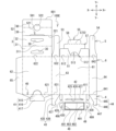
- WIPO (PCT)
- Prior art keywords
- wall
- flap
- storage box
- female
- male
- Prior art date
- Legal status (The legal status is an assumption and is not a legal conclusion. Google has not performed a legal analysis and makes no representation as to the accuracy of the status listed.)
- Ceased
Links
Images




























Classifications
-
- B—PERFORMING OPERATIONS; TRANSPORTING
- B65—CONVEYING; PACKING; STORING; HANDLING THIN OR FILAMENTARY MATERIAL
- B65D—CONTAINERS FOR STORAGE OR TRANSPORT OF ARTICLES OR MATERIALS, e.g. BAGS, BARRELS, BOTTLES, BOXES, CANS, CARTONS, CRATES, DRUMS, JARS, TANKS, HOPPERS, FORWARDING CONTAINERS; ACCESSORIES, CLOSURES, OR FITTINGS THEREFOR; PACKAGING ELEMENTS; PACKAGES
- B65D5/00—Rigid or semi-rigid containers of polygonal cross-section, e.g. boxes, cartons or trays, formed by folding or erecting one or more blanks made of paper
- B65D5/42—Details of containers or of foldable or erectable container blanks
- B65D5/44—Integral, inserted or attached portions forming internal or external fittings
-
- B—PERFORMING OPERATIONS; TRANSPORTING
- B65—CONVEYING; PACKING; STORING; HANDLING THIN OR FILAMENTARY MATERIAL
- B65D—CONTAINERS FOR STORAGE OR TRANSPORT OF ARTICLES OR MATERIALS, e.g. BAGS, BARRELS, BOTTLES, BOXES, CANS, CARTONS, CRATES, DRUMS, JARS, TANKS, HOPPERS, FORWARDING CONTAINERS; ACCESSORIES, CLOSURES, OR FITTINGS THEREFOR; PACKAGING ELEMENTS; PACKAGES
- B65D5/00—Rigid or semi-rigid containers of polygonal cross-section, e.g. boxes, cartons or trays, formed by folding or erecting one or more blanks made of paper
- B65D5/42—Details of containers or of foldable or erectable container blanks
- B65D5/44—Integral, inserted or attached portions forming internal or external fittings
- B65D5/52—External stands or display elements for contents
-
- B—PERFORMING OPERATIONS; TRANSPORTING
- B65—CONVEYING; PACKING; STORING; HANDLING THIN OR FILAMENTARY MATERIAL
- B65D—CONTAINERS FOR STORAGE OR TRANSPORT OF ARTICLES OR MATERIALS, e.g. BAGS, BARRELS, BOTTLES, BOXES, CANS, CARTONS, CRATES, DRUMS, JARS, TANKS, HOPPERS, FORWARDING CONTAINERS; ACCESSORIES, CLOSURES, OR FITTINGS THEREFOR; PACKAGING ELEMENTS; PACKAGES
- B65D5/00—Rigid or semi-rigid containers of polygonal cross-section, e.g. boxes, cartons or trays, formed by folding or erecting one or more blanks made of paper
- B65D5/42—Details of containers or of foldable or erectable container blanks
- B65D5/54—Lines of weakness to facilitate opening of container or dividing it into separate parts by cutting or tearing
-
- B—PERFORMING OPERATIONS; TRANSPORTING
- B65—CONVEYING; PACKING; STORING; HANDLING THIN OR FILAMENTARY MATERIAL
- B65D—CONTAINERS FOR STORAGE OR TRANSPORT OF ARTICLES OR MATERIALS, e.g. BAGS, BARRELS, BOTTLES, BOXES, CANS, CARTONS, CRATES, DRUMS, JARS, TANKS, HOPPERS, FORWARDING CONTAINERS; ACCESSORIES, CLOSURES, OR FITTINGS THEREFOR; PACKAGING ELEMENTS; PACKAGES
- B65D5/00—Rigid or semi-rigid containers of polygonal cross-section, e.g. boxes, cartons or trays, formed by folding or erecting one or more blanks made of paper
- B65D5/42—Details of containers or of foldable or erectable container blanks
- B65D5/56—Linings or internal coatings, e.g. pre-formed trays provided with a blow- or thermoformed layer
-
- B—PERFORMING OPERATIONS; TRANSPORTING
- B65—CONVEYING; PACKING; STORING; HANDLING THIN OR FILAMENTARY MATERIAL
- B65D—CONTAINERS FOR STORAGE OR TRANSPORT OF ARTICLES OR MATERIALS, e.g. BAGS, BARRELS, BOTTLES, BOXES, CANS, CARTONS, CRATES, DRUMS, JARS, TANKS, HOPPERS, FORWARDING CONTAINERS; ACCESSORIES, CLOSURES, OR FITTINGS THEREFOR; PACKAGING ELEMENTS; PACKAGES
- B65D55/00—Accessories for container closures not otherwise provided for
- B65D55/02—Locking devices; Means for discouraging or indicating unauthorised opening or removal of closure
-
- B—PERFORMING OPERATIONS; TRANSPORTING
- B65—CONVEYING; PACKING; STORING; HANDLING THIN OR FILAMENTARY MATERIAL
- B65D—CONTAINERS FOR STORAGE OR TRANSPORT OF ARTICLES OR MATERIALS, e.g. BAGS, BARRELS, BOTTLES, BOXES, CANS, CARTONS, CRATES, DRUMS, JARS, TANKS, HOPPERS, FORWARDING CONTAINERS; ACCESSORIES, CLOSURES, OR FITTINGS THEREFOR; PACKAGING ELEMENTS; PACKAGES
- B65D75/00—Packages comprising articles or materials partially or wholly enclosed in strips, sheets, blanks, tubes or webs of flexible sheet material, e.g. in folded wrappers
- B65D75/52—Details
- B65D75/58—Opening or contents-removing devices added or incorporated during package manufacture
-
- B—PERFORMING OPERATIONS; TRANSPORTING
- B65—CONVEYING; PACKING; STORING; HANDLING THIN OR FILAMENTARY MATERIAL
- B65D—CONTAINERS FOR STORAGE OR TRANSPORT OF ARTICLES OR MATERIALS, e.g. BAGS, BARRELS, BOTTLES, BOXES, CANS, CARTONS, CRATES, DRUMS, JARS, TANKS, HOPPERS, FORWARDING CONTAINERS; ACCESSORIES, CLOSURES, OR FITTINGS THEREFOR; PACKAGING ELEMENTS; PACKAGES
- B65D77/00—Packages formed by enclosing articles or materials in preformed containers, e.g. boxes, cartons, sacks or bags
- B65D77/22—Details
- B65D77/24—Inserts or accessories added or incorporated during filling of containers
- B65D77/26—Elements or devices for locating or protecting articles
-
- B—PERFORMING OPERATIONS; TRANSPORTING
- B65—CONVEYING; PACKING; STORING; HANDLING THIN OR FILAMENTARY MATERIAL
- B65D—CONTAINERS FOR STORAGE OR TRANSPORT OF ARTICLES OR MATERIALS, e.g. BAGS, BARRELS, BOTTLES, BOXES, CANS, CARTONS, CRATES, DRUMS, JARS, TANKS, HOPPERS, FORWARDING CONTAINERS; ACCESSORIES, CLOSURES, OR FITTINGS THEREFOR; PACKAGING ELEMENTS; PACKAGES
- B65D85/00—Containers, packaging elements or packages, specially adapted for particular articles or materials
- B65D85/67—Containers, packaging elements or packages, specially adapted for particular articles or materials for web or tape-like material
Definitions
- the present invention relates to a printing cassette storage body and a sheet.
- Patent Document 1 discloses a storage box that contains ink cartridges that are filled with ink used for printing and are installed in a printing device.
- the ink cartridges are placed in a packaging bag and stored in the storage box in a reduced-pressure packaged state.
- the storage box is not limited to ink cartridges; it can also be used, for example, as a package for storing print cassettes that contain the print medium used for printing.
- the object of the present invention is to provide a printing cassette storage unit and sheet that protects the printing cassette from rubbing against the inner surface of the storage box.
- a printing cassette storage body comprising a printing cassette that is mounted in a printing device and used for printing on a print medium, and a storage box that stores the printing cassette, wherein the storage box or the printing cassette has an inhibitor that inhibits the generation of paper dust from the inner surface of the storage box.
- a printing cassette storage body including a printing cassette that is mounted in a printing device and used for printing on a print medium, and a paper storage box that stores the printing cassette
- a sheet that is configured to be formed by assembling the storage box, and that has an inhibitor that inhibits the generation of paper dust from the inner surface of the storage box when the storage box is assembled. Therefore, the storage box formed by assembling the sheet has an inhibitor that inhibits the generation of paper dust, and therefore prevents a decrease in print quality due to paper dust adhering to the printing cassette stored inside, and ensures quality.
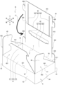
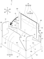
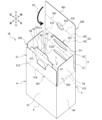
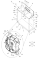
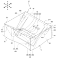
- FIG. 1 is a perspective view of the printing device 10 and the tape cassette 8A as viewed from above, front, left.
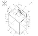
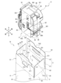
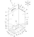
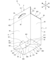
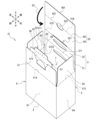
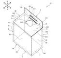
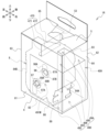
- 1 is a perspective view of the storage box 1A seen from the upper right front.
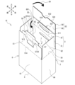
- FIG. 1 is a perspective view of the storage box 1A as seen from the lower, rear left.
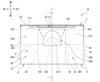
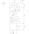
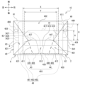
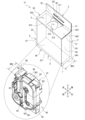
- FIG. 2 is a plan view of storage box 1A.
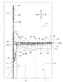
- 5 is a cross-sectional view of the storage box 1A as seen in the direction of the arrows II shown in FIG. 4.
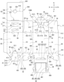
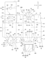
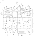
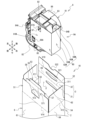
- 1 is an exploded view showing a mount 100A in which the storage box 1A is unfolded.
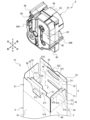
- 1 is a perspective view of a tape cassette 8A and a protective member 9 as viewed from the upper left front.
- FIG. 1 is a perspective view of a tape cassette 8A and a protective member 9 as viewed from the lower left front.
- 2 is a development view showing a protective backing 200 in which the protective member 9 is developed.
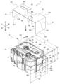
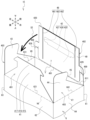
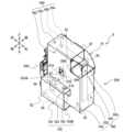
- FIG. 1A to 1C are diagrams showing a process of storing a tape cassette 8A with a protective member 9 attached in a storage box 1A.
- 1A is a diagram showing a state in which the top wall 5 of the storage box 1A storing the tape cassette 8A is being assembled.
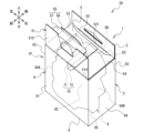
- 1 is a perspective view of the storage box 1B seen from the upper right front.
- FIG. 1B is a perspective view of the storage box 1B seen from the lower, rear left.
- FIG. 1B is a plan view of storage box 1B.
- FIG. 1B is a bottom view of storage box 1B.
- FIG. 13 is a development view showing the mount 100B.
- 1 is a perspective view of the bottom wall 4 of the storage box 1B as viewed from below and rear on the right side.
- 1 is a perspective view of a storage box 1B before the bottom wall 4 is assembled, as seen from below and rear on the right side.
- 18, is a perspective view of the storage box 1B in the middle of assembling the bottom wall 4, as viewed from below and rear on the right side.
- FIG. 19 and is a perspective view of the storage box 1B in the middle of assembling the bottom wall 4, as viewed from below and rear on the right side.
- 1 is a perspective view of a storage box 1B before a top wall 5 is assembled, as seen from above and on the front right.
- FIG. 20 is a perspective view of the storage box 1B in the middle of assembling the top wall 5, as viewed from above and on the front right.
- 1 is a perspective view of a storage box 1C seen from the upper right front.
- FIG. 13 is a development view showing the mount 100C.
- 1 is a perspective view of a storage box 1D before the bottom wall 4 is assembled, as seen from the lower left front.
- 1 is a perspective view of a storage box 1D in the middle of assembling a bottom wall 4, as viewed from below and front left.
- FIG. FIG. 1B is a perspective view of the storage box 1E as seen from the upper right front.
- FIG. 1B is a perspective view of the storage box 1E as seen from the lower, rear left.
- FIG. 1B is a plan view of storage box 1E.
- FIG. 1C is a bottom view of storage box 1E.
- FIG. 13 is a development view showing the mount 100D.
- This is an oblique view of the bottom wall 4 of the storage box 1E as seen from the lower, rear right.
- 1 is a perspective view of a storage box 1E before the bottom wall 4 is assembled, as seen from below and rear on the right side. 33, and is a perspective view of the storage box 1E in the middle of assembling the bottom wall 4, as seen from below and rear on the right side.
- 34 and is a perspective view of the storage box 1E in the middle of assembling the bottom wall 4, as seen from below and rear on the right side.
- FIG. 13 is a development view showing the mount 100E.
- FIG. 1 is a perspective view of the storage box 1G as seen from the upper right front.
- FIG. 1 is a perspective view of the storage box 1G as seen from the lower, rear left.
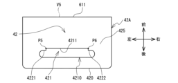
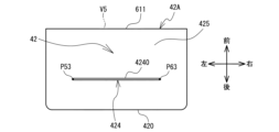
- FIG. 13 is a bottom view of the female flap 42.
- FIG. 1 is a plan view of storage box 1G.
- FIG. 2 is a development view showing the mount 100F.
- 11A and 11B are diagrams showing the process of assembling a storage box 1G from a mount 100F.
- FIG. 48 is a rear view of the storage box 1G of FIG. 47.
- 1 is a perspective view of a storage box 1G opened by a first opening method, as viewed from the lower left rear.
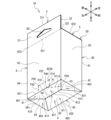
- FIG. This is an oblique view of the storage box 1H as seen from the lower left rear.
- FIG. 13 is a development view showing the mount 100G.
- FIG. 13 is a development view showing the mount 100G.
- FIG. 1 is a perspective view of the storage box 1J as seen from the lower, rear left.
- 1 is a perspective view of the storage box 1K as seen from the lower left rear.
- FIG. 1 is a perspective view of the storage box 1L as seen from the lower left rear.
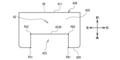
- FIG. 13 is a bottom view of the female flap 42 in which the insertion port 423 is provided.
- FIG. 4 is a bottom view of the female flap 42 in which the receptacle 424 is provided.
- 1 is a perspective view of the printing device 10 and the tape cassette 8 as viewed from below, front right. This is an oblique view of the storage box 1N as seen from the upper right front. This is an oblique view of the storage box 1N as seen from the lower left rear.
- FIG. 1 is a plan view of storage box 1N.
- 1 is a development view showing a mount 100H on which a storage box 1N is developed.
- 11A to 11C are diagrams showing the process of storing the tape cassette 8 in the storage box 1N.
- 13 is a diagram showing a state in which protruding pieces 75B and 76B are inserted into a tape cassette 8 stored in a storage box 1N.
- 11 is a perspective view of a storage box 1N in which the protruding length of protruding pieces 175A, 176A can be changed.
- FIG. 1 is a perspective view of the printing device 10 and the tape cassette 8 as viewed from above, front, and left. This is an oblique view of the storage box 1P seen from the upper right front. 1 is a perspective view of the storage box 1P seen from the lower left rear.
- FIG. 2 is a plan view of storage box 1P. This is a cross-sectional view of storage box 1P as seen in the direction of the arrows IV-IV shown in Figure 69.
- 1 is a development view showing a mount 100J on which a storage box 1P is developed.
- 11A to 11C are diagrams showing the process of storing the tape cassette 8 in the storage box 1P.
- FIG. 13 is a diagram showing a state in which a tape cassette 8 stored in a storage box 1P is pressed by a pressing portion 70.
- FIG. 11 is a diagram for explaining the length of pressing portions 70 and 75.
- FIG. 1 is a perspective view of a storage box 1P equipped with pressing portions 170, 175, and 180.
- FIG. 1 is a perspective view of a storage box 1P equipped with pressing portions 270 and 275.
- FIG. 13 is a development view showing a mounting sheet 205 in which the mounting member 9A is developed.
- FIG. 11A and 11B are diagrams showing a process of storing the tape cassette 8 with the mounting member 9A attached in the storage box 1R.
- FIG. 1A is a diagram showing a state in which the tape cassette 8 stored in the storage box 1R is pressed by the pressing portion 90 of the mounting member 9A.
- FIG. 1 is a perspective view of a storage box 1R that stores a tape cassette 8 with a mounting member 409 attached thereto.
- FIG. 13 is a perspective view of the tape cassette 8 with the mounting member 509 mounted thereon.
- the tape cassette 8A will be described with reference to FIG. 1.
- the top, bottom, bottom right, top left, bottom left, and top right in FIG. 1 are respectively the top, bottom, front, rear, left, and right of the tape cassette 8A.
- the orientation of the printing device 10 will follow the orientation of the tape cassette 8A when it is attached, regardless of whether the tape cassette 8A is attached to the printing device 10 or not.
- the orientation of the storage box 1A and the orientation of the protective member 9 described below will follow the orientation of the tape cassette 8A when it is attached to the protective member 9 and stored in the storage box 1A (see FIG. 11).
- the up and down directions are used for convenience of explanation and are not limited to the vertical direction.
- the tape cassette 8A comprises a case 81, a printing tape 89, and an ink ribbon 87.
- the case 81 is a generally rectangular parallelepiped that is longer in the left-right direction than in the front-rear direction, and is longer in the up-down direction than in the left-right direction.
- the case 81 has a front wall 82, a rear wall 83, and a peripheral wall 84.
- the front wall 82 and the rear wall 83 each extend perpendicular to the front-rear direction, and are aligned with each other in the front-rear direction.
- the front wall 82 is located at the front end of the case 81.
- the rear wall 83 is located at the rear end of the case 81.
- the peripheral wall 84 extends from the periphery 831 of the rear wall 83 to the periphery 821 of the front wall 82.
- the peripheral wall 84 is in the shape of a rectangular tube, and includes a bottom wall 85 and an upper wall 86.
- the bottom wall 85 and the upper wall 86 each extend perpendicular to the up-down direction, and are aligned with each other in the up-down direction.
- the bottom wall 85 is located at the bottom end of the case 81.
- the upper wall 86 is located at the top end of the case 81.
- the upper wall 86 is provided with an outlet 88 for discharging the print tape 89 stored in the case 81 to the outside of the case 81.
- the outlet 88 is located at approximately the same height as the upper wall 86 in the vertical direction or slightly above it.
- the printing tape 89 is long and wound around a cylindrical tape spool 89A and stored in the case 81.
- the tape spool 89A is located in the upper right corner of the case 81, with both ends supported by the front wall 82 and rear wall 83.
- a cylindrical hole 89B in the tape spool 89A is exposed to the outside of the case 81 at the front wall 82 and rear wall 83.
- the cylindrical hole 89B is used to position the tape cassette 8A within the mounting section 11 of the printing device 10.
- the width direction (short direction) of the printing tape 89 is the front-to-rear direction. Therefore, the width direction of the tape cassette 8A is the front-to-rear direction. With the tape cassette 8A, if the length in the width direction (tape width) of the printing tape 89 increases, the width of the case 81 in the front-to-rear direction increases.
- the ink ribbon 87 is long and wound around a ribbon spool (not shown) and stored in the case 81.
- the ink ribbon 87 passes through a path where it overlaps with the printing tape 89 on its way from the tape spool 89A to the discharge port 88, and is taken up by a cylindrical take-up spool 87A.
- the take-up spool 87A is located in the lower left part of the case 81, and both ends are supported by the front wall 82 and the rear wall 83.
- the cylindrical hole of the take-up spool 87A is a cam hole 87B formed with a cam through which a driving force for winding up the ink ribbon 87 is input.
- the cam hole 87B is exposed to the outside of the case 81 at the front wall 82 and the rear wall 83.
- protrusions 861, 851 are provided on the upper wall 86 and the lower wall 85 of the case 81, respectively.
- the protrusion 861 is rib-shaped, extending in the left-right direction while protruding upward at approximately the center of the upper wall 86, and is the structure that protrudes most upward on the upper wall 86. In other words, the protrusion 861 protrudes upward above the discharge port 88.
- the left and right ends of the protrusion 861 are each formed as a rib extending in the front-rear direction, and are H-shaped in plan view.
- the protrusion 851 is rib-shaped, extending in the left-right direction while protruding downward at approximately the center of the lower wall 85, and is the structure that protrudes most downward on the lower wall 85.
- the left and right ends of the protrusion 851 are each formed as a rib extending in the front-rear direction, and are H-shaped in bottom view.
- a recess 80 is formed in the middle of the right side of the case 81 in the vertical direction, from the front wall 82 to the right peripheral wall 84.
- the printing device 10 has a recessed mounting section 11 that opens on the front side for mounting the tape cassette 8A.
- a hook 12 that extends forward from the bottom wall of the recess is formed near the inner wall of the recess at the upper part of the mounting section 11.
- a hook 13 that extends forward from the bottom wall of the recess is also formed near the inner wall of the recess at the lower part of the mounting section 11.
- the tape cassette 8A is a consumable item, and is used for printing by the printer 10. With the tape cassette 8A attached to the attachment section 11, the printer 10 pulls out the printing tape 89 from inside the case 81 while transferring ink from the ink ribbon 87 to the printing tape 89 using a print head (not shown), thereby printing an image. The printer 10 ejects the printing tape 89 with the image printed on it from the case 81 via the ejection port 88. This creates a label with the image printed on the printing tape 89.
- the storage box 1A will be described with reference to Figures 2 to 6.
- the storage box 1A is formed, for example, by assembling a backing 100A as shown in Figure 6.
- the storage box 1A comprises a box body 2 and a header 3.
- the box body 2 is a rectangular parallelepiped that is longer in the left-right direction than in the front-rear direction and longer in the top-down direction than in the left-right direction, and stores a tape cassette 8A.
- the box body 2 has a bottom wall 4, a top wall 5, and peripheral walls 6.
- the bottom wall 4 and the top wall 5 each extend perpendicular to the top-down direction and are aligned with each other in the top-down direction.
- the bottom wall 4 is located at the bottom end of the box body 2.
- the top wall 5 is located at the top end of the box body 2.
- the peripheral wall 6 extends from the periphery 40 of the bottom wall 4 to the periphery 50 of the top wall 5.
- the peripheral wall 6 is in the shape of a rectangular tube and includes a front wall 61, a back wall 62, a left wall 63, and a right wall 64.
- the front wall 61 and the back wall 62 each extend perpendicular to the front-to-rear direction and are aligned with each other in the front-to-rear direction.
- the front wall 61 is located at the front end of the box body 2.
- the back wall 62 is located at the rear end of the box body 2.
- the left wall 63 and the right wall 64 each extend perpendicular to the left-to-right direction and are aligned with each other in the left-to-right direction.
- the left wall 63 is located at the left end of the box body 2.
- the right wall 64 is located at the right end of the box body 2.
- the lower end 611 of the front wall 61, the lower end 621 of the back wall 62, the lower end 631 of the left wall 63, and the lower end 641 of the right wall 64 form the periphery 40 of the bottom wall 4 (see Figure 3).
- the upper end 612 of the front wall 61, the upper end 622 of the back wall 62, the upper end 632 of the left wall 63, and the upper end 642 of the right wall 64 form the periphery 50 of the top wall 5 (see Figure 2).
- a space 7 is formed inside the box body 2.
- the space 7 is surrounded by a bottom wall 4, a top wall 5, and peripheral walls 6 (front wall 61, rear wall 62, left wall 63, right wall 64).
- the tape cassette 8A is placed in the space 7 with the bottom wall 85 of the case 81 facing the bottom wall 4 of the box body 2 from above.
- the header 3 is provided on the box body 2.
- the header 3 is wall-shaped and includes a header piece 31 and a header piece 32.
- the header piece 31 is connected to the upper end 622 of the back wall 62 and extends upward from the upper end 622 of the back wall 62.
- the imaginary line V0 in FIG. 3 indicates the upper end 622 of the back wall 62.
- the header piece 32 is folded back forward from the upper end 311 of the header piece 31 and extends downward.
- the lower end 321 of the header piece 32 is located at the top wall 5 in the vertical direction and is connected to a female flap 52 (see FIG. 4) described below.
- a hole 30 is provided in the header 3.
- the hole 30 is an isosceles triangle in a front view and is located in the left-right center of the header 3.
- the hole 30 penetrates the header pieces 31, 32 in the front-rear direction.
- the hole 30 penetrates the header 3 in the front-rear direction.
- the storage boxes 1A may be inserted through the hole 30 onto a rod for hanging and displaying products, and may be hung and displayed.
- the bottom wall 4 is a so-called bottom of the pit, and includes a male flap 41, a female flap 42, a left flap 43, and a right flap 44.
- the male flap 41 is connected to the lower end 621 of the back wall 62 and extends forward from the lower end 621 of the back wall 62.
- the male flap 41 is trapezoidal in shape, narrowing toward the front.
- the female flap 42 is connected to the lower end 611 of the front wall 61 and extends rearward from the lower end 611 of the front wall 61.
- the female flap 42 is rectangular in shape, longer in the left-right direction than in the front-to-rear direction.
- An insertion port 421 is formed in the female flap 42.
- the insertion port 421 is longer in the left-right direction than in the front-to-rear direction, and penetrates the female flap 42 in the vertical direction.
- the left flap 43 is connected to the lower end 631 of the left wall 63 and extends rightward from the lower end 631 of the left wall 63.
- the right flap 44 is connected to the lower end 641 of the right wall 64 and extends leftward from the lower end 641 of the right wall 64.
- the left flap 43 and the right flap 44 are each triangular and symmetrical to each other.
- the female flap 42, the left flap 43, the right flap 44, and the male flap 41 are stacked in that order from top to bottom to form the bottom wall 4.
- the top wall 5 includes a male flap 51, a female flap 52, a left flap 53, and a right flap 54.
- the male flap 51 is connected to the upper end 612 of the front wall 61, and has a male main body portion 515 and an insertion portion 55.
- the male main body portion 515 extends rearward from the upper end 612 of the front wall 61.
- the male main body portion 515 is rectangular in shape and is longer in the left-right direction than in the front-to-back direction.
- the length of the male main body portion 515 in the front-to-back direction is approximately the same as the distance between the front wall 61 and the rear wall 62 in the front-to-back direction.
- the rear end 511 of the male main body portion 515 is located near the front of the rear wall 62 and extends in the left-to-right direction.
- the male main body portion 515 has an opening 513 that penetrates the male main body portion 515 in the up-down direction.
- the opening 513 is a portion where a user places his or her finger when opening the storage box 1A.
- the insertion portion 55 is connected to the male main body portion 515 and protrudes downward from the rear end 511 of the male main body portion 515.
- the insertion portion 55 includes a base portion 57 and a return portion 58.
- the base portion 57 is the portion of the insertion portion 55 that extends downward from the male main body portion 515.
- the base portion 57 is rectangular in shape and is longer in the left-right direction than in the up-down direction.
- the base portion 57 is connected to the male main body portion 515 at the center portion in the left-right direction of the rear end 511 of the male main body portion 515, and both end portions are separated from the male main body portion 515.
- the return portion 58 is folded backward along a perforation at the lower end 571 of the base portion 57 and extends upward.
- the return portion 58 is located between the back wall 62 and the base portion 57 in the front-rear direction and contacts the back wall 62.
- the female flap 52 is connected to the upper end 622 of the back wall 62 via the header 3, extends forward from the lower end 321 of the header piece 32 (see FIG. 6), then folds back and extends rearward.
- the female flap 52 is rectangular in shape and is longer in the left-right direction than in the front-to-back direction.
- the front end 520 of the female flap 52 is located approximately in the center of the top wall 5 in the front-to-back direction.
- the female flap 52 is provided with a finger hook 522 and an insertion port 521 (see FIG. 6).
- the finger hook 522 is recessed rearward from the center in the left-right direction at the front end 520 of the female flap 52.
- the finger hook 522 is arc-shaped and overlaps with the opening 513 in a plan view (see FIG. 4).
- the insertion port 521 is longer in the left-right direction than in the front-to-back direction, and penetrates the female flap 52 in the up-down direction.
- the insertion port 521 is located rearward of the center in the front-to-back direction between the front wall 61 and the rear wall 62, and is located near the rear wall 62.
- the insertion port 521 is located at the connection portion of the female flap 52 with the header piece 32 (the rear end of the female flap 52).
- the insertion portion 55 is inserted into the insertion port 521.
- the left flap 53 is connected to the upper end 632 of the left wall 63 and extends to the right from the upper end 632 of the left wall 63.
- the right flap 54 is connected to the upper end 642 of the right wall 64 and extends to the left from the upper end 642 of the right wall 64.
- the left flap 53 and the right flap 54 are each rectangular in shape that is longer in the left-right direction than in the front-to-back direction, and are symmetrical to each other.
- a cutout 531 is provided in the left flap 53. The cutout 531 cuts out the rear end of the left flap 53 forward.
- a cutout 541 is provided in the right flap 54. The cutout 541 cuts out the rear end of the right flap 54 forward.
- each of the left flap 53 and the right flap 54 is smaller than the left-right distance between the left wall 63 and the right wall 64, and is greater than half the left-right distance between the left wall 63 and the right wall 64. Therefore, one of the right end of the left flap 53 and the left end of the right flap 54 overlaps the other. In the first embodiment, the left flap 53 overlaps the right flap 54.
- the layer formed by the male flap 51 is referred to as the "male flap layer 501".
- the outer shape of the male flap layer 501 is determined by the outer shape of the male main body portion 515.
- the layer formed by the female flap 52 is referred to as the "female flap layer 502".
- the outer shape of the female flap layer 502 is determined by the outer shape of the female flap 52.
- the layer formed by the left flap 53 and the right flap 54 is referred to as the "side flap layer 503".
- the outer shape of the side flap layer 503 is determined by the outer shapes of the left flap 53 and the right flap 54.
- the male flap layer 501, the female flap layer 502, and the side flap layer 503 are stacked in the order of female flap layer 502, side flap layer 503, and male flap layer 501 from bottom to top.
- the insertion portion 55 is positioned inside the female flap 52 via the insertion port 521.
- the left flap 53 and the right flap 54 are provided with cutout portions 531 and 541, respectively, so that the side flap layer 503 does not overlap with the insertion port 521 in a plan view.
- the mount 100A will be described with reference to FIG. 6.
- the left, right, bottom, and top in FIG. 6 are respectively the negative X direction, positive X direction, negative Y direction, and positive Y direction of the mount 100A.
- imaginary lines V0, V1, V2, V3, V4, V5, V6, V7, V8, V9, V10, V11, V12, V13, and V14 indicate the boundaries between adjacent components of the storage box 1A.
- imaginary line V0 indicates the boundary between the back wall 62 and the header piece 31.
- the mount 100A is a sheet cut into a predetermined shape and is made of paper material such as thick paper, thin paper, or corrugated cardboard. Note that the mount 100A of the first embodiment is not coated on at least the back side.
- the "back side" of the mount 100A is the side of the mount 100A shown in FIG. 6 that faces the back side of the paper and faces the internal space 7 of the storage box 1A when the storage box 1A is assembled.
- Known coating processes for paper materials include, for example, a process of applying varnish to the surface of the mount 100A, a process of applying a gloss agent to the surface and press coating it, a process of laminating, applying a film such as PP or PET, and a process of applying polyvinyl chloride resin.
- the front surface of the mount 100A may or may not be coated.
- the "front side” of mount 100A is the side of mount 100A shown in FIG. 6 that faces the front side of the page, and is the side that faces the outside of storage box 1A when storage box 1A is assembled.
- the mount 100A includes a bottom wall 4, a top wall 5, a peripheral wall 6, and a header 3.
- the peripheral wall 6 is located in the center in the Y direction.
- the front wall 61, the back wall 62, the left wall 63, and the right wall 64 are arranged in a row from the X-positive direction to the X-negative direction in the order of right wall 64, front wall 61, left wall 63, and back wall 62.
- a glue margin 65 is arranged next to the back wall 62 in the X-negative direction.
- the bottom wall 4 is positioned in the negative Y direction of the peripheral wall 6.
- the male flap 41 is positioned in the negative Y direction of the back wall 62 and is connected to the back wall 62.
- the female flap 42 is positioned in the negative Y direction of the front wall 61 and is connected to the front wall 61.
- the left flap 43 is positioned in the negative Y direction of the left wall 63 and is connected to the left wall 63.
- the right flap 44 is positioned in the negative Y direction of the right wall 64 and is connected to the right wall 64.
- the top wall 5 and the header 3 are arranged in the Y-positive direction of the peripheral wall 6.
- the header piece 31 is arranged in the Y-positive direction of the back wall 62 and is connected to the back wall 62.
- the header piece 32 is arranged in the Y-positive direction of the header piece 31 and is connected to the header piece 31.
- the female flap 52 is positioned in the Y-positive direction of the header piece 31 and is connected to the header piece 31.
- the male flap 51 is positioned in the Y-positive direction of the front wall 61 and is connected to the front wall 61.
- the left flap 53 is positioned in the Y-positive direction of the left wall 63 and is connected to the left wall 63.
- the right flap 54 is positioned in the Y-positive direction of the right wall 64 and is connected to the right wall 64.
- the protective member 9 will be described with reference to Figures 7 to 9.
- the protective member 9 is formed, for example, by assembling the protective backing 200 shown in Figure 9.
- the protective member 9 is attached to the tape cassette 8A when storing the tape cassette 8A in the storage box 1A, and is stored in the storage box 1A together with the tape cassette 8A.
- the protective member 9 has a positioning portion 93 and protective portions 91, 92.
- the positioning portion 93 is a portion that is disposed facing the front wall 82 of the tape cassette 8A, and is a rectangular plate that extends longer in the up-down direction than in the left-right direction.
- the left-right length P2 of the positioning portion 93 is shorter than the left-right length C2 of the case 81 of the tape cassette 8A.
- the up-down length P1 of the positioning portion 93 is longer than the up-down length C1 of the case 81 of the tape cassette 8A.
- the positioning section 93 has a rectangular cutout 94 that is recessed from the right end 933 toward the left at approximately the center in the vertical direction to approximately the center in the horizontal direction.
- the position of the cutout 94 is the position of the recess 80 to which the label sticker 80A is affixed when the protective member 9 is attached to the tape cassette 8A and the positioning section 93 is viewed from the front. In other words, a worker storing the tape cassette 8A in the storage box 1A can see the label sticker 80A through the cutout 94 even when the protective member 9 is attached to the tape cassette 8A.
- the positioning portion 93 has a cutout portion 95A, which is located above the notch 94 and toward the right of the center in the left-right direction, with the upper edge and both left and right edges cut out in the thickness direction (front-to-back direction) while leaving the lower edge.
- the cutout portion 95A is long in the vertical direction, and the corners between the upper edge and both left and right edges are rounded.
- the inner part of the cutout portion 95A is the engagement portion 95, which is bent backward along the lower edge and protrudes backward from the positioning portion 93.
- the left-to-right length of the engagement portion 95 is the same as or slightly shorter than the inner diameter of the cylindrical hole 89B.
- the front-to-back length of the engagement portion 95 is shorter than the front-to-back length C3 of the case 81 of the tape cassette 8A.
- the positioning portion 93 has a cutout portion 96A at a position below and to the left of the notch 94, which is obtained by cutting out the lower side and both left and right sides in the thickness direction (front-to-back direction) while leaving the upper side.
- the cutout portion 96A is long in the vertical direction, and the corners between the lower side and both left and right sides are rounded.
- the inner part of the cutout portion 96A is the engagement portion 96, which is bent backward along the upper side and protrudes backward from the positioning portion 93.
- the left-to-right length of the engagement portion 96 is the same as or slightly shorter than the inner diameter of the cam hole 87B, and is longer than the left-to-right length of the engagement portion 95.
- the front-to-back length of the engagement portion 96 is shorter than the front-to-back length C3 of the case 81 of the tape cassette 8A and shorter than the front-to-back length of the engagement portion 95.
- the protective portion 91 is connected to the upper end 931 of the positioning portion 93 and extends rearward from the upper end 931 of the positioning portion 93.
- the protective portion 91 is a rectangular plate, and the corners between the rear end 911 and both left and right ends are rounded.
- the left-right length of the protective portion 91 is the same length P2 as the left-right length P2 of the positioning portion 93, which is shorter than the left-right length C2 of the case 81 of the tape cassette 8A and longer than the left-right length H1 of the protrusion 861 provided on the upper wall 86.
- the front-rear length P3 of the protective portion 91 is shorter than the front-rear length C3 of the case 81 of the tape cassette 8A and longer than the front-rear length H3 of the protrusion 861 provided on the upper wall 86 of the tape cassette 8A when the protective member 9 attached to the tape cassette 8A is viewed from above, the protective portion 91 is positioned to cover the entire formation area W1 of the protrusion 861 in both the left-right and front-rear directions (see FIG. 7).
- the rib-like portions extending in the front-rear direction from both the left and right ends of the protrusion 861 have their ends chamfered in the direction of protrusion (upward) from the top wall 86.
- the chamfered portions are not the portion of the top wall 86 that protrudes most upward, they do not need to be included in the formation region W1 of the protrusion 861, and therefore the chamfered portions do not necessarily need to be covered by the protective portion 91.
- the protective portion 92 is connected to the lower end 932 of the positioning portion 93 and extends rearward from the lower end 932 of the positioning portion 93.
- the protective portion 92 is a rectangular plate, and the corners between the rear end 921 and both left and right ends are rounded.
- the left-right length of the protective portion 92 is length P2, which is the same as the left-right length P2 of the positioning portion 93 and the protective portion 91, and is shorter than the left-right length C2 of the case 81 of the tape cassette 8A and longer than the left-right length H2 of the protrusion 851 provided on the bottom wall 85.
- the front-rear length P4 of the protective portion 92 is shorter than the front-rear length C3 of the case 81 of the tape cassette 8A and longer than the front-rear length H4 of the protrusion 851 provided on the bottom wall 85 of the tape cassette 8A.
- the protective portion 92 is positioned to cover the entire formation area W2 of the protrusion 851 in both the left-right and front-back directions (see FIG. 8).
- the rib-shaped portions extending in the front-back direction from both the left and right ends of the protrusion 851 have their ends chamfered in the direction of protrusion (downward) from the bottom wall 85.
- the chamfered portions are not the portion of the bottom wall 85 that protrudes furthest downward, they do not need to be included in the formation area W2 of the protrusion 851, and therefore the chamfered portions do not necessarily need to be covered by the protective portion 92.
- the protective backing 200 will be described with reference to Figure 9.
- the left, right, bottom, and top in Figure 9 are respectively the negative X direction, positive X direction, negative Y direction, and positive Y direction of the backing 100A.
- virtual lines V21, V22, V23, and V24 indicate the boundaries between adjacent components of the protective member 9.
- virtual line V21 indicates the boundary between the positioning portion 93 and the protective portion 91.
- the protective mount 200 is a sheet cut to a predetermined shape and is made from paper material such as thick paper, thin paper, or corrugated cardboard. In the first embodiment, the protective mount 200 has a coating portion formed on the back side.
- the "back side” of the protective mount 200 is the surface of the protective mount 200 shown in FIG. 9 that faces the back side of the paper.
- the protective member 9 is assembled by folding the protective mount 200 so that the back sides 91A, 92A, and 93A on which the coating portions are formed in the protective portions 91 and 92 and the positioning portion 93, respectively, face the tape cassette 8A when the protective member 9 is attached to the tape cassette 8A.
- the "front side” is the surface of the protective mount 200 shown in FIG. 9 that faces the front side of the paper.
- the protective mount 200 When the protective member 9 is assembled and attached to the tape cassette 8A, the front surface faces the outside of the tape cassette 8A, and when the protective member 9 is stored in the storage box 1A, the protective mount 200 is folded and assembled so that it faces the back surface of the storage box 1A.
- coating processes for paper materials are known, for example, a process of applying varnish to the back surface of the protective mount 200, a process of applying a gloss agent to the back surface and press coating it, a process of laminating, applying a film such as PP or PET, and a process of applying vinyl chloride resin.
- the type of coating process does not matter, and any of the above processes may be applied to the protective mount 200.
- the coating portion may be partially formed on the back surface of the protective mount 200.
- the coating portion may be formed on the back surfaces 91A and 92A of the protective portions 91 and 92, and not on the back surface 93A of the positioning portion 93.
- the protective backing 200 includes a positioning section 93 and protective sections 91 and 92.
- the positioning section 93 is located in the center in the Y direction.
- a cutout section 94 is formed at the end of the positioning section 93 on the X plus direction side.
- the cutout section 94 is recessed in a rectangular shape toward the X minus direction.
- An engagement section 95 is formed on the Y plus direction side of the cutout section 94.
- the periphery of the engagement section 95 is cut out as a cutout section 95A, leaving the end on the Y minus direction side.
- an engagement section 96 is formed on the X minus direction side of the cutout section 94, on the Y minus direction side of the center in the Y direction.
- the periphery of the engagement section 96 is cut out as a cutout section 96A, leaving the end on the Y plus direction side.
- the protective section 91 is located on the Y plus direction side of the positioning section 93.
- the protective section 92 is located on the Y minus direction side of the positioning section 93.
- mount 100A is folded along the imaginary line V1 in a direction in which the back surfaces of the right wall 64 and the front wall 61 face each other.
- creases are formed on the front surface of the mount 100A along the imaginary lines V0 to V14.
- creases are formed on the front surface of the protective mount 200 along the imaginary lines V21 to V24.
- no creases are formed on the back surfaces of the mount 100A and the protective mount 200.
- the mount 100A is folded along imaginary lines V1, V2, V3, and V4, and the surface of the glue tab 65 is attached to the back surface of the left wall 63.
- the surface of the mount 100A, including each of the flaps, faces the outside of the rectangular tube, and the back surface faces inward, i.e., toward the inside of the space 7.
- the mount 100A is mountain-folded along the imaginary line V5.
- the female flap 42 is arranged on the top layer of the bottom wall 4 as the female flap layer 402.
- the mount 100A is mountain-folded along the imaginary lines V6 and V7.
- the left flap 43 and the right flap 44 are stacked below the female flap layer 402 as the side flap layer 403.
- the mount 100A is mountain-folded along the imaginary line V8.
- the male flap 41 is stacked below the side flap layer 403 as the male flap layer 401, and is arranged on the bottom layer of the bottom wall 4. In this state, the male flap 41 is pushed inward from the outside.
- the box body 2 opens upward (see Figure 3).
- the protective member 9 is assembled and attached to the tape cassette 8A.
- the protective member 9 may be assembled in advance before assembling the storage box 1A.
- the protective backing 200 is mountain-folded along imaginary lines V21 and V22. This positions the protective portions 91 and 92 in a state extending toward the rear. Furthermore, the protective backing 200 is mountain-folded along imaginary lines V23 and V24. This positions the engagement portions 95 and 96 in a state extending toward the rear, completing the assembly of the protective member 9.
- the worker orients the back surface 93A of the positioning portion 93 of the protective member 9 toward the front wall 82 of the tape cassette 8A, and inserts the engagement portions 95 and 96 into the cylindrical hole 89B and the cam hole 87B, respectively, to attach the protective member 9 to the tape cassette 8A.
- the protective portions 91 and 92 of the protective member 9 are arranged with the back surfaces 91A and 92A on which the coating is formed facing the upper wall 86 and lower wall 85 of the tape cassette 8A, respectively.
- the tape cassette 8A with the protective member 9 attached is stored in the space 7 from above the box body 2.
- the tape cassette 8A is stored in the space 7 with the rear wall 83 facing the rear surface of the back wall 62 of the storage box 1A from the front and the lower wall 85 facing the rear surface of the bottom wall 4 from above.
- the worker can visually check the label sticker 80A through the cutout portion 94 of the protective member 9 to confirm whether the information on the tape cassette 8A matches the information on the stored items printed on the storage box 1A.
- the positioning portion 93 of the protective member 9 is disposed between the front wall 82 of the tape cassette 8A and the front wall 61 of the storage box 1A inside the storage box 1A. Therefore, the upper end 931 of the positioning portion 93 is disposed at the corner portion between the front wall 61 and the top wall 5 in the front-to-rear direction.
- the mount 100A is mountain-folded along the imaginary line V9 and valley-folded along the imaginary line V10. As a result, as shown in FIG. 11, the header 3 is formed, and the female flap layer 502 is placed on the bottom layer of the top wall 5.
- the mount 100A is mountain-folded along the imaginary lines V11 and V12.
- the side flap layer 503 composed of the left flap 43 and the right flap 54 is stacked on top of the female flap layer 502 on the top wall 5. Note that in the side flap layer 503, the left flap 43 and the right flap 54 may be stacked in any order.
- the mount 100A is mountain-folded along the imaginary line V13 and valley-folded along the perforation at the bottom end 571 of the base portion 57. As a result, the insertion portion 55 is formed.
- the mount 100A is folded along the imaginary line V14.
- the insertion portion 55 is inserted through the insertion port 521, inside the female flap 52.
- the protective portion 91 of the protective member 9 is disposed between the upper wall 86 of the tape cassette 8A and the female flap 52 of the storage box 1A.
- the upper end 931 of the positioning portion 93 which is the connection portion between the positioning portion 93 and the protective portion 91, is located at the corner portion between the front wall 61 and the top wall 5 in the front-rear direction in the storage box 1A.
- the protective member 9 is not disposed at the corner portion between the back wall 62 and the top wall 5 in the storage box 1A.
- the insertion port 521 into which the insertion portion 55 is inserted is located at the rear end of the female flap 52. Therefore, the insertion portion 55 does not interfere with the protective member 9 when inserted into the insertion port 521.
- the male flap layer 501 is laminated on the side flap layer 503, and the top wall 5 shown in FIG. 2 is formed. This completes the assembly of the storage box 1A and the protective member 9, and the storage of the tape cassette 8A inside the storage box 1A, completing the printing cassette storage body 20 shown in FIG. 11 (however, the printing cassette storage body 20 in FIG. 11 is in a state before the top wall 5 is formed).
- the upper wall 86 and lower wall 85 of the tape cassette 8A are provided with protrusions 861, 851, respectively.
- Protrusion 861 protrudes upward from the upper wall 86
- protrusion 851 protrudes downward from the lower wall 85.
- Formation areas W1, W2 of protrusions 861, 851 are covered in the vertical direction by protective portions 91, 92 of protective member 9, respectively.
- Engagement portions 95, 96 provided on positioning portion 93 of protective member 9 engage with cylindrical hole 89B and cam hole 87B opening in the front wall 82 of case 81 of tape cassette 8A.
- positioning portion 93 positions protective member 9 relative to tape cassette 8A. Therefore, protective portions 91, 92 are positioned relative to protrusions 861, 851. Even if the tape cassette 8A is shaken in the space 7 due to transportation after being stored in the storage box 1A, the protrusions 861 and 851 maintain their positional relationship with the protective parts 91 and 92, so they are not easily rubbed.
- a coating is formed on the backsides 91A, 92A of the protective parts 91, 92, and the protrusions 861, 851 come into contact with the coating. Even if the storage box 1A is shaken violently when being carried, etc., causing a misalignment between the protrusions 861, 851 and the protective parts 91, 92, the protrusions 861, 851 will rub against the coating without coming into contact with the top wall 5 and bottom wall 4 of the storage box 1A.
- the formation of the coating on the backsides 91A, 92A of the protective parts 91, 92 provides sufficient protection from wear caused by friction, which can prevent the generation of paper dust and the like caused by rubbing.
- the protective member 9 is attached to the tape cassette 8A and stored in the storage box 1.
- the protective member 9 prevents friction between the tape cassette 8A and the storage box 1A, and suppresses the generation of paper dust from the inner surface of the storage box 1A. Therefore, the tape cassette 8A stored in the storage box 1A can prevent a decrease in print quality due to the adhesion of paper dust, and ensure quality.
- the storage box 1A is formed by assembling the backing paper 100A.
- the storage box 1A has a protective member 9 that can suppress the generation of paper dust, preventing a decrease in print quality caused by paper dust adhering to the tape cassette 8A contained inside, and ensuring quality.
- the protective parts 91, 92 protect the protrusions 861, 851 on the upper wall 86 and lower wall 85 of the case 81 from coming into direct contact with the inner surface of the storage box 1A.
- a coating is formed on the back surfaces 91A, 92A of the protective parts 91, 92 that face the upper wall 86 and lower wall 85 of the case 81. Therefore, the protective member 9 suppresses the generation of paper dust even if the protrusions 861, 851 rub against the protective parts 91, 92. Therefore, the tape cassette 8A stored in the storage box 1A can prevent a decrease in print quality due to the adhesion of paper dust, and ensure quality.
- the protective member 9 includes a positioning portion 93 that connects to the protective portions 91, 92.
- the positioning portion 93 engages with the front wall 82 of the case 81 to position the protective portions 91, 92 relative to the protrusions 861, 851.
- the protective member 9 is formed by folding a single protective backing 200, with the positioning portion 93 positioned opposite the front wall 82 of the case 81, and the protective portions 91, 92 positioned opposite the upper wall 86 and lower wall 85 of the case 81.
- the front wall 82 of the case 81 is positioned on the front wall 61 side of the storage box 1A. Therefore, the connection portion between the protective portions 91, 92 and the positioning portion 93 is positioned on the side closer to the upper end 612 of the front wall 61.
- the insertion port 521 of the female flap 52 is provided near the upper end 622 of the back wall 62, and when the insertion portion 55 of the male flap 51 is inserted into the insertion port 521, there is no interference with the connection portion between the protective portions 91, 92 and the positioning portion 93.
- the free ends of the protective portions 91, 92 are positioned on the side closer to the upper end 622 of the back wall 62. Therefore, when storing the tape cassette 8A in the storage box 1A, the worker can smoothly insert the insertion portion 55 into the insertion opening 521 by appropriately swinging the protective portions 91 and 92.
- the protective portions 91 and 92 of the protective member 9 can prevent friction between the inner surface of the storage box 1A and the protrusions 861 and 851 of the case 81. Therefore, even if no coating is formed on the inner surface of the storage box 1A, the storage box 1A can sufficiently suppress the generation of paper dust. This allows the manufacturing cost of the storage box 1A to be reduced.
- the length of the protective parts 91, 92 in the front-to-rear direction is shorter than that of the case 81, so when inserting the insertion part 55 of the male flap 51 into the insertion port 521, the insertion part 55 is unlikely to interfere with the free ends of the protective parts 91, 92. This allows the worker to smoothly insert the insertion part 55 into the insertion port 521 when storing the tape cassette 8A in the storage box 1A.
- the protective portions 91, 92 are large enough to cover the entire formation areas W1, W2 of the protrusions 861, 851, and are smaller than the upper wall 86 and the lower wall 85 of the case 81. Therefore, the protective member 9 can be made small while still being large enough to prevent friction between the inner surface of the storage box 1A and the protrusions 861, 851 of the case 81. This allows the manufacturing costs of the protective member 9 to be reduced.
- the worker can check the label sticker 80A through the cutout 94, even with the protective member 9 attached to the case 81. This prevents the worker from mistaking the tape cassette 8A.
- the worker is less likely to store the tape cassette 8A in the storage box 1A in the wrong direction, and by correctly positioning the positioning portion 93 between the front wall 61 of the storage box 1A and the front wall 82 of the case 81, the operator can smoothly insert the insertion portion 55 into the insertion port 521.
- the protrusions 861, 851 are necessary for mounting the tape cassette 8A in the printing device 10, and are the parts that protrude most outward on the upper wall 86 and lower wall 85 of the case 81. For this reason, even if the tape cassette 8A is stored as is in the storage box 1A, it is difficult to prevent friction between the protrusions 861, 851 and the inner surface of the storage box 1A. Therefore, by arranging the protective members 91, 92 between the inner surface of the storage box 1A and the protrusions 861, 851, the protective member 9 can suppress the generation of paper dust due to friction.
- the protective member 9 has protrusions 861, 851 formed on the outer surface of at least one of the upper wall 86 where the discharge port 88 of the case 81 is formed and the lower wall 85 on the opposite side, the outer surface can be protected by at least one of the protective parts 91 and 92 where a coating is formed. Therefore, the tape cassette 8A stored in the storage box 1A can prevent a decrease in print quality due to the adhesion of paper powder, and can ensure quality.
- the printing tape 89 is an example of the "printed medium” of the present invention.
- the tape cassette 8A is an example of the "printing cassette” of the present invention.
- the protective member 9 is an example of the "restraining member” of the present invention.
- the upper wall 86 and the lower wall 85 are an example of the "protrusion forming surface” of the present invention.
- the back surfaces 91A and 92A are an example of the "opposing surface” of the present invention.
- the printing cassette storage body 20 in which the tape cassette 8A with the protective member 9 attached is stored in the storage box 1A is an example of the "printing cassette storage body" of the present invention.
- the front wall 82 is an example of the "positioning surface” of the present invention.
- the cylindrical hole 89B and the cam hole 87B are an example of the "engaged portion" of the present invention.
- the up-down direction is an example of the "first direction” of the present invention.
- the top wall 5 is an example of the “second wall” of the present invention.
- the bottom wall 4 is an example of the "first wall” of the present invention.
- the front-rear direction is an example of the "second direction” of the present invention.
- the front wall 61 is an example of the "third wall” of the present invention.
- the back wall 62 is an example of a "fourth wall” of the present invention.
- the upward direction is an example of a "first specific direction” of the present invention.
- the upper end 612 is an example of a "first connecting end" of the present invention.
- the rear direction is an example of a "second specific direction" of the present invention.
- the rear end 511 is an example of a "rear end” of the present invention.
- the male flap 51 is an example of a "first male flap” of the present invention.
- the male flap layer 501 is an example of a “first male flap layer” of the present invention.
- the upper end 622 is an example of a “second connecting end” of the present invention.
- the female flap 52 is an example of a "first female flap” of the present invention.
- the female flap layer 502 is an example of a "first female flap layer” of the present invention.
- the protective backing 200 is an example of a "sheet” of the present invention.
- the left-right direction is an example of a "third direction” of the present invention.
- the label sticker 80A is an example of a "label” of the present invention.
- the recess 80 is an example of an "attachment portion” of the present invention.
- the outlet 88 is an example of an "outlet” of the present invention.
- the upper wall 86 is an example of the “second cassette wall” of the present invention.
- the lower wall 85 is an example of the "first cassette wall” of the present invention.
- the present invention may be modified from the first embodiment.
- the various modified examples of the first embodiment described below may be combined with each other as long as no contradictions arise.
- the protrusions 861 and 851 are not limited to protrusions, and may be uneven or have a surface with unevenness, or may have a shape that may rub against the corners or edges of stored items and generate paper dust.
- the protrusions 861 and 851 are formed on the upper wall 86 and the lower wall 85, respectively, but may be formed on either one of them, or may be formed on the peripheral wall 84, the front wall 82, or the rear wall 83 other than the upper wall 86 and the lower wall 85.
- the discharge port 88 and the protrusion 861 are provided on the upper wall 86, but may be provided on different wall surfaces.
- the coating portion is formed on the back surface 91A, 92A, 93A of the protective backing 200, it may be formed on both the front surface and back surface 91A, 92A, 93A, or it may not be formed on the back surface 93A of the positioning portion 93 but may be formed on the back surfaces 91A, 92A of the protective portions 91, 92. Also, the coating portion may be formed not on the entire back surfaces 91A, 92A of the protective portions 91, 92, but only in areas that may come into contact with the formation areas W1, W2 of the protrusions 861, 851.
- the number of engagement parts 95, 96 of the positioning part 93 is not limited to two, and may be one, or three or more.
- the parts with which the engagement parts 95, 96 engage are not limited to the cylindrical hole 89B and the cam hole 87B, and may be other holes or recesses.
- the protective member 9 may be wrapped around and fixed to the outer surface of the case 81 to position the protective parts 91, 92.
- the protective member 9 may not have the positioning portion 93 and may simply consist of the protective portions 91 and 92.
- the protective portion 91 covering the protrusion 861 of the upper wall 86 of the case 81 and the protective portion 92 covering the protrusion 851 of the lower wall 85 may each be formed from two protective backings 200 as separate protective members 9.
- the protective member 9 in this modified example has a coating formed on the surfaces of the protective portions 91 and 92 that are arranged facing the case 81 inside the storage box 1A.
- the size of the protective portions 91 and 92 may be such that they can always cover (overlap in a direction perpendicular to the surface) the formation areas W1 and W2 of the protrusions 861 and 851 even when the protective portions 91 and 92 move in a direction horizontal to the surface inside the case 81.
- multiple protective parts may be connected together to form a protective member 9 made of a single protective backing 200.
- the multiple protective parts cover the outer surfaces of the case 81 on which the protrusions are formed, but they do not need to be positioned relative to the case 81.
- the two protective parts may be connected adjacent to each other on the protective backing 200, and the protective member 9 may be assembled by folding the surface on which the coating is formed inward.
- the protective parts 91 and 92 are arranged on the upper wall 86 and the lower wall 85 as in the first embodiment, a part that is arranged opposite the front wall 82, such as the positioning part 93, may be provided, but the engagement parts 95 and 96 may not be formed and may simply be parts for connection.
- the protective backing 200 is not limited to paper, and may be made of, for example, a plastic sheet, as long as it is a sheet that can be folded and maintained in a folded state.
- the protective member 9 may protect other stored items instead of the tape cassette 8A.
- the other stored items are, for example, consumables used for printing, such as ink tanks, ink cartridges, or ink ribbon cassettes.
- the other stored items may also be consumables used for purposes other than printing.
- the other stored items do not have to be consumables, and may be food, etc.
- the tape cassette 8A may be stored upside down in the storage box 1A, but it is preferable to store it so that the positioning portion 93 is positioned on the front wall 82 side of the storage box 1A.
- the header 3 of the storage box 1A may be omitted, or may be composed of only one of the header pieces 31, 32.
- the bottom wall 4 of the storage box 1A is not limited to the shape of a bottom of the cradle, and may be in the shape of a so-called caramel box, for example.
- Storage box 1B will be described with reference to Figures 12 and 13.
- the upper left, lower right, lower left, upper right, lower, and upper in Figure 12 will be referred to as the left, right, front, rear, lower, and upper of storage box 1B, respectively.
- the up and down directions are used for convenience of explanation and are not limited to the vertical direction.
- the storage box 1B is formed by assembling, for example, a mount 100B shown in FIG. 16.
- the mount 100B of the second embodiment has a coating portion formed on its front surface.
- the "front surface” of the mount 100B is the surface of the mount 100B shown in FIG. 16 that faces the viewer on the page.
- the storage box 1B is assembled by folding the mount 100B so that the surfaces on which the coating portions are formed on the top wall 5, bottom wall 4, and peripheral wall 6 face outward.
- the "reverse surface” is the surface of the mount 100B shown in FIG. 16 that faces the depth of the page. When the storage box 1B is assembled, the mount 100B is folded so that the reverse surface faces the space 7 inside the box.
- Known coating processes for paper include, for example, a process of applying varnish to the surface of the mount 100B, a process of applying a gloss agent to the surface and press-coating it, a process of laminating, applying a film such as PP or PET, and a process of applying vinyl chloride resin.
- the type of coating process does not matter, and any of the above processes may be applied to the mount 100B.
- the configuration of the mount 100B and the method of assembling the storage box 1B from the mount 100B will be described later.
- the storage box 1B comprises a box body 2 and a header 3.
- the box body 2 is a rectangular parallelepiped that is longer in the left-right direction than in the front-to-back direction and longer in the top-to-bottom direction than in the left-to-right direction, and stores a tape cassette 8B.
- the front-to-back width W21 of the box body 2 is slightly larger than the front-to-back width W81 of the tape cassette 8B.
- the relationship between the lengths of the box body 2 in the front-to-back, left-to-right, and top-to-bottom directions is the same as the relationship between the lengths of the tape cassette 8B in the front-to-back, left-to-right, and top-to-bottom directions.
- the box body 2 has a bottom wall 4, a top wall 5, and peripheral walls 6.
- the bottom wall 4 and the top wall 5 each extend perpendicular to the vertical direction and are aligned with each other in the vertical direction.
- the bottom wall 4 is located at the lower end of the box body 2.
- the top wall 5 is located at the upper end of the box body 2.
- the peripheral wall 6 extends from the periphery 40 of the bottom wall 4 to the periphery 50 of the top wall 5.
- the peripheral wall 6 is in the shape of a rectangular tube and includes a front wall 61, a back wall 62, a left wall 63, and a right wall 64.
- the front wall 61 and the back wall 62 each extend perpendicular to the front-to-rear direction and are aligned with each other in the front-to-rear direction.
- the front wall 61 is located at the front end of the box body 2.
- the back wall 62 is located at the rear end of the box body 2.
- the left wall 63 and the right wall 64 each extend perpendicular to the left-to-right direction and are aligned with each other in the left-to-right direction.
- the left wall 63 is located at the left end of the box body 2.
- the right wall 64 is located at the right end of the box body 2.
- the lower end 611 of the front wall 61, the lower end 621 of the back wall 62, the lower end 631 of the left wall 63, and the lower end 641 of the right wall 64 form the periphery 40 of the bottom wall 4 (see FIG. 13).
- the upper end 612 of the front wall 61, the upper end 622 of the back wall 62, the upper end 632 of the left wall 63, and the upper end 642 of the right wall 64 form the periphery 50 of the top wall 5 (see FIG. 12).
- a space 7 is formed inside the box body 2.
- the space 7 is surrounded by a bottom wall 4, a top wall 5, and peripheral walls 6 (front wall 61, back wall 62, left wall 63, right wall 64).
- a tape cassette 8B is placed in the space 7 with a lower wall 85 (described below) facing the bottom wall 4 from above.
- the header 3 is provided on the box body 2.
- the header 3 is wall-shaped and includes a header piece 31 and a header piece 32.
- the header piece 31 is connected to the upper end 622 of the back wall 62 and extends upward from the upper end 622 of the back wall 62.
- the upper end 622 of the back wall 62 is shown by an imaginary line V0.
- the header piece 32 is folded back forward from the upper end 311 of the header piece 31 and extends downward.
- the lower end 321 of the header piece 32 is located at the top wall 5 in the vertical direction and is connected to a female flap 52 (see FIG. 14) described below.
- the header 3 is provided with a hole 30.
- the hole 30 is an isosceles triangle in a front view and is located in the left-right center of the header 3.
- the hole 30 penetrates the header pieces 31, 32 in the front-rear direction.
- the hole 30 penetrates the header 3 in the front-rear direction.
- the storage boxes 1B may be inserted through the hole 30 onto a rod for hanging and displaying products, and may be hung and displayed.
- the top wall 5 includes a male flap 51, a female flap 52, a left flap 53, and a right flap 54.
- the male flap 51 is connected to the upper end 612 of the front wall 61, and has a male main body portion 515 and an insertion portion 55.
- the male main body portion 515 extends rearward from the upper end 612 of the front wall 61.
- the male main body portion 515 is rectangular in shape and is longer in the left-right direction than in the front-to-rear direction.
- the front-to-rear length of the male main body portion 515 is approximately the same as the front-to-rear distance between the front wall 61 and the rear wall 62.
- the rear end 511 of the male main body portion 515 is located near the front of the back wall 62 and extends in the left-right direction.
- the male main body portion 515 includes an opening edge 512.
- the opening edge 512 defines an opening 513.
- the opening 513 penetrates the male main body portion 515 in the up-down direction.
- the opening edge 512 is closed in a ring shape and includes edges 5121 and 5122.
- the edge 5121 is positioned rearward of the opening 513.
- the edge 5121 extends in the left-right direction and is an arc shape that bulges rearward.
- the edge 5122 extends forward from the left end of the edge 5121, then extends to the right, then extends rearward to connect to the right end of the edge 5121.
- the edge 5122 is positioned rearward of the upper end 612 of the front wall 61. Therefore, the area of the top wall 5 near the upper end 612 of the front wall 61 is continuous in the left-right direction without being divided by the opening 513.
- the male main body portion 515 is provided with a pair of perforations 516, 517.
- the perforation 516 extends leftward as it moves rearward from the left end of the edge 5121 to the rear end 511 of the male main body portion 515.
- the perforation 517 extends rightward as it moves rearward from the left end of the edge 5121 to the rear end 511 of the male main body portion 515. Therefore, the pair of perforations 516, 517 extend away from each other in the left-right direction as it moves rearward.
- the area of the male main body portion 515 surrounded by the end 5111, the perforations 516, 517, and the edge 5121 is referred to as the "opening area R22."
- the user can open the storage box 1B from the top wall 5 side by separating the opening area R22 from the box main body 2.
- the insertion portion 55 is connected to the male main body portion 515 and protrudes downward from the rear end 511 of the male main body portion 515.
- the insertion portion 55 includes a base portion 57 and a return portion 58.
- the base portion 57 is the portion of the insertion portion 55 that extends downward from the male main body portion 515.
- the base portion 57 is rectangular in shape and is longer in the left-right direction than in the up-down direction.
- the base portion 57 is connected to the rear end 511 of the male main body portion 515, at the portion between the perforations 516 and 517.
- the return portion 58 is folded back at the perforation 5722 formed at the lower end of the base portion 57 and extends upward.
- the return portion 58 is located between the back wall 62 and the base portion 57 in the front-rear direction and contacts the back wall 62.
- the female flap 52 is connected to the upper end 622 of the back wall 62 via the header 3, extends forward from the lower end 321 of the header piece 32 (see Figure 16), and then folds back and extends rearward.
- the female flap 52 is rectangular in shape and is longer in the left-right direction than in the front-to-rear direction.
- the female flap 52 has a folded base 59 and a folded end 60.
- the folded base 59 is approximately rectangular in shape and connects to the lower end 321 of the header piece 32 and extends forward.
- the size of the folded base 59 is approximately the same as the area surrounded by the upper ends 612, 622, 632, and 642 of the peripheral wall 6 when the storage box 1B is assembled.
- the front end 591 of the folded base 59 is located near the upper end 612 of the front wall 61 in the front-to-rear direction.
- the folded end 60 is approximately rectangular in shape and connects to the front end 591 of the folded base 59 and extends rearward.
- the size of the folded end 60 in the left-right direction is the same as that of the folded base 59 in the left-right direction, and the size of the folded end 60 in the front-to-rear direction is slightly shorter than the size of the folded base 59 in the left-to-right direction.
- the folded end 60 is a portion folded back from the lower side at the front end 591 of the folded base 59, and is located below the folded base 59, i.e., on the space 7 side, when the top wall 5 is assembled.
- the rear end 601 of the folded end 60 is located forward of the upper end 622 of the back wall 62 in the front-to-rear direction.
- the rear end 601 is located forward of the insertion port 521, which will
- the female flap 52 is provided with a finger hook 522 and an insertion port 521 (see FIG. 16).
- the finger hook 522 is formed at a position where the midpoint of the front end 591 of the folded base 59 is the center of a circle. Therefore, in a plan view with the folded tip 60 folded back, the finger hook 522 has a semicircular recess extending rearward from the front end 591 of the folded base 59.
- the insertion port 521 is longer in the left-right direction than in the front-to-back direction, and penetrates the female flap 52 in the up-down direction.
- the insertion port 521 is located rearward of the center in the front-to-back direction between the front wall 61 and the rear wall 62, and is located near the rear wall 62.
- the insertion port 521 is located at the location where the folded base 59 of the female flap 52 connects to the header piece 32 (the rear end of the folded base 59).
- the insertion portion 55 is inserted into the insertion port 521.
- the left flap 53 is connected to the upper end 632 of the left wall 63 and extends to the right from the upper end 632 of the left wall 63.
- the right flap 54 is connected to the upper end 642 of the right wall 64 and extends to the left from the upper end 642 of the right wall 64.
- the left flap 53 and the right flap 54 are each rectangular in shape that is longer in the left-right direction than in the front-to-back direction, and are symmetrical to each other.
- the left and right lengths of the left and right flaps 53, 54 are smaller than the left and right distance between the left and right walls 63, 64, and are greater than half the left and right distance between the left and right walls 63, 64. Thus, one of the right end of the left flap 53 and the left end of the right flap 54 overlaps the other. In the second embodiment, the left flap 53 overlaps the right flap 54.
- the layer formed by the male flaps 51 is referred to as the "male flap layer 501".
- the outer shape of the male flap layer 501 is determined by the outer shape of the male main body portion 515.
- the layer formed by the female flaps 52 is referred to as the "female flap layer 502".
- the outer shape of the female flap layer 502 is determined by the outer shape of the folded base portion 59.
- the layer formed by the left flap 53 and the right flap 54 is referred to as the "side flap layer 503".
- the outer shape of the side flap layer 503 is determined by the outer shapes of the left flap 53 and the right flap 54.
- the male flap layer 501, the female flap layer 502, and the side flap layer 503 are stacked in the order of the female flap layer 502, the side flap layer 503, and the male flap layer 501 from bottom to top.
- the insertion portion 55 is positioned on the inside of the female flap 52 via the insertion port 521.
- a perforation 623 is provided on the back wall 62.
- the perforation 623 is an arc shape that bulges upward, and is located at the bottom of the back wall 62. Both ends of the perforation 623 are located at the bottom end 621 of the back wall 62.
- the area of the back wall 62 surrounded by the perforation 623 and the bottom end 621 of the back wall 62 is referred to as the "starting point area R11."
- the user pushes the starting point area R11 into the box body 2, and uses it as a starting point for separating the opening area R12 (described later) from the box body 2.
- the bottom wall 4 is a so-called bottom, and includes a male flap 41, a female flap 42, a fold-back flap 49, a left flap 43, and a right flap 44.
- the male flap 41 is connected to the lower end 621 of the back wall 62, and extends forward from the lower end 621 of the back wall 62.
- the male flap 41 has a male main body portion 415, an insertion portion 416, and a head portion 417.
- the male main body portion 415 is a portion that extends forward from the lower end 621 of the back wall 62, and has a trapezoidal shape that narrows toward the front.
- the length of the male main body portion 415 in the front-to-rear direction is approximately the same as half the length of the box main body 2 in the front-to-rear direction (the length of the lower end 631 of the left wall 63), or slightly shorter.
- the insertion portion 416 is a portion that protrudes forward from the male main body portion 415, and extends forward while maintaining the same left-right length at the extended tip of the male main body portion 415.
- the head portion 417 is a portion that protrudes further forward from the insertion portion 416, and extends longer in the left-right direction than the insertion portion 416.
- the left end of the head portion 417 protrudes leftward beyond the left edge of the insertion portion 416, and the right end of the head portion 417 protrudes rightward beyond the right edge of the insertion portion 416.
- the left-right length of the head portion 417 is longer than the left-right length of the insertion portion 416.
- the head portion 417 functions to prevent the insertion portion 416 from slipping out of the insertion port 426 (described below) of the female flap 42 when inserted into the insertion port 426.
- the male flap 41 has a pair of perforations 411, 412.
- the perforation 411 extends leftward from the left end of both ends of the perforation 623 as it moves forward.
- the perforation 412 extends rightward from the right end of both ends of the perforation 623 as it moves forward.
- the area of the male flap 41 surrounded by the pair of perforations 411, 412 and the lower end 621 of the back wall 62 is referred to as the "opening area R12."
- the user can open the storage box 1B from the bottom wall 4 side by separating the opening area R12 together with the starting area R11 from the box body 2.
- the female flap 42 is connected to the lower end 611 of the front wall 61 and extends rearward from the lower end 611 of the front wall 61.
- the female flap 42 has a female main body portion 425 and engagement portions 428, 429, and an insertion port 426 and a guide port 427 are formed in the female main body portion 425.
- the female main body portion 425 is a portion that extends rearward from the lower end 611 of the front wall 61, and has a rectangular shape that is longer in the left-right direction than in the front-to-rear direction.
- the left-to-right length of the female flap 42 is shorter than the left-to-right length of the box body 2 (the length of the lower end 611 of the front wall 61) by the left-to-right length of the engagement portions 428, 429.
- the front-to-rear length of the female flap 42 is approximately the same size as the front-to-rear length of the box body 2 (the length of the lower end 631 of the left wall 63).
- the engagement portions 428, 429 are provided on both the left and right sides at the front end of the female flap 42 in the front-to-rear direction.
- the engaging portions 428, 429 extend rearward from the lower end 611 of the front wall 61 with their sides connected to the female main body portion 425.
- the protruding tip portions of the engaging portions 428, 429 are separated from the left and right edges of the female main body portion 425 and can bend in the vertical direction.
- the size of the female flap 42, including the engaging portions 428, 429, is approximately the same size as the area surrounded by the lower ends 611, 621, 631, 641 of the peripheral wall 6 when the storage box 1B is assembled.
- the female flap 42 has an insertion port 426 formed.
- the insertion port 426 is a rectangular opening that is long in the left-right direction and penetrates the female flap 42 in the up-down direction.
- the insertion port 426 is formed rearward of the center in the front-to-back direction of the female flap 42.
- the front opening edge of the insertion port 426 is located approximately in the center in the front-to-back direction of the bottom wall 4 or slightly rearward of that.
- the guide opening 427 is formed on the rear side of the insertion opening 426 and is connected to the insertion opening 426.
- the guide opening 427 extends longer in the left-right direction than the insertion opening 426, both ends are rounded in an arc shape, and penetrates the female flap 42 in the up-down direction.
- the insertion opening 426 and the guide opening 427 are one connected opening that penetrates the female flap 42 in the thickness direction at approximately the center before the storage box 1B is assembled.
- the insertion portion 416 is guided into the insertion opening 426 connected to the guide opening 427, and is inserted through the insertion opening 426. Therefore, the left-right length of the guide opening 427 is greater than or equal to the left-right length of the head 417.
- the folded flap 49 is connected to the rear end 420 of the female flap 42 and extends rearward.
- the folded flap 49 is generally rectangular in shape, longer in the left-right direction than in the front-rear direction.
- the size of the folded flap 49 is generally the same as the size of the female main body portion 425 of the female flap 42.
- engaged portions 498, 499 are formed, each extending in the front-rear direction.
- the engaged portions 498, 499 each have a shape that protrudes forward, and the protruding tip portions are separated from the left and right edges of the folded flap 49, allowing them to bend in the vertical direction.
- the folded flap 49 is folded upward at the rear end 420 of the female flap 42, and is located on the upper side of the female flap 42, i.e., on the space 7 side, when the bottom wall 4 is assembled.
- the engaged portions 498, 499 engage with the engaging portions 428, 429 of the female flap 42, respectively. Therefore, the folded flap 49 is maintained in almost intimate contact with the female flap 42 above the female flap 42.
- a cutout 48 is formed in the fold-back flap 49.
- the cutout 48 penetrates the fold-back flap 49 in the thickness direction and extends along the surface of the fold-back flap 49.
- the cutout 48 has a pair of first cutouts 481, 482 that extend in the front-rear direction at the left and right ends of the fold-back flap 49, respectively, and a second cutout 483 that connects the rear ends of the first cutouts 481, 482 in the left-right direction.
- the cutout 48 has a rectangular shape cut into three sides in a plan view of the fold-back flap 49.
- the left flap 43 is connected to the lower end 631 of the left wall 63 and extends to the right from the lower end 631 of the left wall 63.
- the right flap 44 is connected to the lower end 641 of the right wall 64 and extends to the left from the lower end 641 of the right wall 64.
- the left flap 43 has a left main body portion 435 and a left protruding portion 436.
- the right flap 44 has a right main body portion 445 and a right protruding portion 446.
- the left flap 43 and the right flap 44 are symmetrical to each other.
- the left main body portion 435 has a generally triangular shape extending to the right from the lower end 631 of the left wall 63.
- the rear edge of the left main body portion 435 extends to the right from the rear end of the lower end 631, and the front edge extends diagonally rear to the right from the front end of the lower end 631.
- the right rear end of the front edge of the left main body portion 435 is positioned near the left front corner of the insertion port 426 of the female flap 42 when the bottom wall 4 is assembled.
- the left protrusion 436 protrudes to the right from the extending tip of the left main body 435.
- the left protrusion 436 extends longer in the front-to-rear direction than in the left-to-right direction.
- the front end 437 of the left protrusion 436 protrudes slightly forward from the extending tip of the left main body 435.
- the left-to-right length of the left flap 43 is approximately the same as or shorter than half the left-to-right length of the box main body 2 (the length of the lower end 621 of the back wall 62).
- the right main body portion 445 has a generally triangular shape extending leftward from the lower end 641 of the right wall 64.
- the rear edge of the right main body portion 445 extends leftward from the rear end of the lower end 641, and the front edge extends diagonally rearward to the left from the front end of the lower end 641.
- the left rear end of the front edge of the right main body portion 445 is positioned near the right front corner of the insertion port 426 of the female flap 42 when the bottom wall 4 is assembled.
- the right protrusion 446 protrudes leftward from the extending tip of the right main body 445.
- the right protrusion 446 extends longer in the front-to-rear direction than in the left-to-right direction.
- the front end 447 of the right protrusion 446 protrudes slightly forward from the extending tip of the right main body 445.
- the left-to-right length of the right flap 44 is approximately the same as or shorter than half the left-to-right length of the box main body 2 (the length of the lower end 621 of the back wall 62).
- the layer formed by the male flaps 41 is referred to as the "male flap layer 401".
- the outer shape of the male flap layer 401 is determined by the outer shape of the male main body portion 415.
- the layer formed by the female flaps 42 is referred to as the "female flap layer 402".
- the outer shape of the female flap layer 402 is determined by the outer shape of the female main body portion 425.
- the layer formed by the left flap 43 and the right flap 44 is referred to as the "side flap layer 403".
- the outer shape of the side flap layer 403 is determined by the outer shapes of the left main body portion 435 and the right main body portion 445.
- the male flap layer 401, female flap layer 402, and side flap layer 403 are stacked in the order of female flap layer 402, side flap layer 403, male flap layer 401 from top to bottom.
- the insertion portion 416 and head portion 417 of the male flap 41 are positioned above the female main body portion 425 of the female flap 42 via the insertion port 426, i.e., within the space 7 of the box main body 2.
- the tape cassette 8B will be described with reference to Figure 12.
- the tape cassette 8B comprises a case 81 and a printed tape 89.
- the case 81 is a rectangular parallelepiped that is longer in the left-right direction than in the front-to-back direction, and is longer in the up-down direction than in the left-right direction.
- the printed tape 89 is long and is stored in the case 81.
- the width direction (short direction) of the printed tape 89 is the front-to-back direction. Therefore, the width direction of the tape cassette 8B is the front-to-back direction.
- the front-to-back width W81 of the case 81 increases.
- the case 81 has a front wall 82, a rear wall 83, and a peripheral wall 84.
- the front wall 82 and the rear wall 83 each extend perpendicular to the front-to-rear direction and are aligned with each other in the front-to-rear direction.
- the front wall 82 is located at the front end of the case 81.
- the rear wall 83 is located at the rear end of the case 81.
- the peripheral wall 84 extends from the periphery 831 of the rear wall 83 to the periphery 821 of the front wall 82.
- the peripheral wall 84 is in the shape of a rectangular tube and includes a lower wall 85 and an upper wall 86.
- the lower wall 85 and the upper wall 86 each extend perpendicular to the vertical direction and are aligned with each other in the vertical direction.
- the lower wall 85 is located at the lower end of the case 81.
- the upper wall 86 is located at the upper end of the case 81.
- the upper wall 86 is provided with an outlet 88 for discharging the printing tape 89 stored in the case 81 to the outside of the case 81.
- the outlet 88 protrudes upward beyond the upper wall 86.
- the upper wall 86 and the lower wall 85 are each provided with protrusions 861, 851 that are positioned and held by claws (not shown) provided on the mounting portion when the tape cassette 8B is mounted in a printer (not shown).
- the protrusion 861 protrudes upward from the upper wall 86, and the protrusion 851 protrudes downward from the lower wall 85.
- the tape cassette 8B is a consumable item, and is used for printing by the printer.
- the tape cassette 8B is used while attached to the printer.
- the printer prints an image on the printing tape 89 while pulling the printing tape 89 out of the case 81.
- the printer ejects the printing tape 89 with the image printed on it out of the case 81 through the ejection port 88. This creates a label with the image printed on the printing tape 89.
- the mount 100B will be described with reference to FIG. 16.
- the left, right, bottom, and top of FIG. 16 are respectively the negative X direction, positive X direction, negative Y direction, and positive Y direction of mount 100B.
- imaginary lines V0, V1, V2, V3, V4, V5, V6, V7, V8, V9, V10, V11, V12, V13, V14, V15, and V16 indicate the boundaries between adjacent components of storage box 1B.
- imaginary line V0 indicates the boundary between the back wall 62 and the header piece 31.
- the mount 100B is a sheet cut to a predetermined shape, and may be thick paper, thin paper, corrugated cardboard, or the like.
- the mount 100B includes a bottom wall 4, a top wall 5, a peripheral wall 6, and a header 3.
- the peripheral wall 6 is located in the center in the Y direction.
- the front wall 61, the back wall 62, the left wall 63, and the right wall 64 are lined up in the order of right wall 64, front wall 61, left wall 63, and back wall 62, respectively, from the X-positive direction to the X-negative direction.
- a glue allowance 65 is connected next to the back wall 62 in the X-negative direction.
- the bottom wall 4 is positioned in the negative Y direction of the peripheral wall 6.
- the male flap 41 is positioned in the negative Y direction of the back wall 62 and is connected to the back wall 62.
- the female flap 42 is positioned in the negative Y direction of the front wall 61 and is connected to the front wall 61.
- the left flap 43 is positioned in the negative Y direction of the left wall 63 and is connected to the left wall 63.
- the right flap 44 is positioned in the negative Y direction of the right wall 64 and is connected to the right wall 64.
- the folded flap 49 is disposed in the negative Y direction of the female flap 42 and is connected to the female flap 42.
- the first recess 481 is formed along the Y direction on the side closer to the edge of the female flap 42 in the negative X direction, from the rear end 420 of the female flap 42 to a position further rearward than the front end 491 of the folded flap 49.
- the first recess 482 is formed along the Y direction on the side closer to the edge of the female flap 42 in the positive X direction, from the rear end 420 of the female flap 42 to a position further rearward than the front end 491 of the folded flap 49.
- the second cutout 483 extends in the X direction and connects the ends of the first recesses 481 and 482. Thus, the cutout 48 separates the central portion of the folded flap 49 into a rectangular shape, leaving the front end side.
- the top wall 5 and the header 3 are arranged in the Y-positive direction of the peripheral wall 6.
- the header piece 31 is arranged in the Y-positive direction of the back wall 62 and is connected to the back wall 62.
- the header piece 32 is arranged in the Y-positive direction of the header piece 31 and is connected to the header piece 31.
- the female flap 52 is positioned in the Y-positive direction of the header piece 31 and is connected to the header piece 31.
- the male flap 51 is positioned in the Y-positive direction of the front wall 61 and is connected to the front wall 61.
- the left flap 53 is positioned in the Y-positive direction of the left wall 63 and is connected to the left wall 63.
- the right flap 54 is positioned in the Y-positive direction of the right wall 64 and is connected to the right wall 64.
- a method of assembling a storage box 1B from a mount 100B will be described with reference to Figures 16 to 22.
- Folding the mount 100B along the boundary between adjacent components in a direction in which the back faces of the components face each other is called a "mountain fold”.
- Folding the mount 100B along the boundary between adjacent components in a direction in which the front faces of the components face each other is called a "valley fold”.
- "mountain-folding the mount 100B along the imaginary line V1” means that the mount 100B is folded along the imaginary line V1 in a direction in which the back faces of the right wall 64 and the front wall 61 face each other.
- creases are formed on the front face of the mount 100B along the imaginary lines V1 to V16.
- no creases are formed on the back face of the mount 100B.
- the mount 100B is mountain-folded along imaginary lines V1, V2, V3, and V4.
- the surface of the glue tab 65 is attached to the back surface of the left wall 63.
- the peripheral wall 6 is formed into a rectangular tube shape, as shown in FIG. 18.
- the surface of the mount 100B, including each of the flaps faces the outside of the rectangular tube, and the back surface faces inward, i.e., toward the inside of the space 7.
- the mount 100B is mountain-folded along the imaginary line V15. As shown by the arrow S1, the fold-back flap 49 is folded backward. As a result, as shown in FIG. 19, the fold-back flap 49 is positioned behind the female flap 42. The engaged portions 498, 499 of the fold-back flap 49 engage with the engaging portions 428, 429 of the female flap 42, respectively. As a result, the back surface of the mount 100B at the fold-back flap 49 is kept in close contact with the back surface of the mount 100B at the female flap 42. The front surface of the mount 100B at the fold-back flap 49 faces backward.
- the mount 100B is folded along the imaginary line V5.
- the female flap 42 and the folded flap 49 are folded backwards and placed in the area surrounded by the lower ends 611, 621, 631, and 641 of the peripheral wall 6 (in other words, the opening formed by the periphery 40 of the peripheral wall 6 and connected to the space 7).
- the female flap layer 402 is placed on the top layer of the bottom wall 4.
- the folded flap 49 is placed in a state where the surface on which the coating portion is formed faces into the space 7 and is in close contact with the upper surface of the female flap 42 that constitutes the female flap layer 402.
- the surface on which the coating portion is formed of the folded flap 49 constitutes the lower wall surface in the space 7 and is placed facing upward in the space 7.
- the coating portion formed on the surface of the folded flap 49 comes into contact with the lower surface of the lower wall 85 of the tape cassette 8B contained in the space 7.
- the mount 100B is mountain-folded along the imaginary lines V6 and V7.
- the left flap 43 is folded to the right, and the right flap 44 is folded to the left, and they are arranged in the area surrounded by the lower ends 611, 621, 631, and 641 of the peripheral wall 6.
- the left flap 43 and the right flap 44 are stacked below the female flap layer 402 as the side flap layer 403.
- the mount 100B is mountain-folded along the imaginary line V8.
- the male flap 41 is folded forward, and they are arranged in the area surrounded by the lower ends 611, 621, 631, and 641 of the peripheral wall 6.
- the male flap 41 is stacked below the side flap layer 403 as the male flap layer 401, and they are arranged in the lowest layer of the bottom wall 4.
- the male flap 41 is pushed inward from the outside.
- the left flap 43 and right flap 44 are pushed by the male flap 41 and pushed inward from the outside.
- the female flap 42 is pushed by the male flap 41, left flap 43 and right flap 44 and pushed inward from the outside.
- the male flap 41, female flap 42, left flap 43 and right flap 44 are each inclined diagonally from the lower ends 611, 621, 631 and 641 of the peripheral wall 6 toward the space 7.
- the head 417 of the male flap 41 reaches the guide opening 427 of the female flap 42 and is inserted through the guide opening 427.
- the insertion portion 416 is inserted through the guide opening 427, and the male flap 41 is released from being pushed in, so that the insertion portion 416 is guided into the insertion opening 426.
- the head 417 of the male flap 41 which is inclined obliquely into the space 7, comes into contact with the folded flap 49, but the central portion cut off by the cutout portion 48 bends more toward the rear end 420 of the female flap 42, so the movement of the insertion portion 416 into the insertion opening 426 is not restricted.
- the male flap 41, left flap 43, and right flap 44 are each caught by the female flap 42 via the insertion opening 426, forming a bottom wall 4 in the shape of a bottom of the earth.
- the male flap 41 is released from being pressed down, so that the folded flap 49 is in close contact with the female flap 42, with the head 417 and insertion portion 416 sandwiched between it and the female flap 42, with the surface of the mount 100B facing into the space 7.
- the box body 2 opens upward.
- the tape cassette 8B is stored in the space 7 from above the box body 2 so that the bottom wall 85 faces the back surface of the bottom wall 4 from above.
- the folded flap 49 is in close contact with the upper surface of the female flap 42 in the uppermost female flap layer 402 of the bottom wall 4, and is arranged with the surface of the folded flap 49 on which the coating portion is formed facing into the space 7.
- the tape cassette 8B is placed on the surface of the backing 100B of the folded flap 49 in the space 7.
- the bottom wall 85 of the tape cassette 8B is provided with a protrusion 851.
- the protrusion 851 protrudes downward beyond the bottom wall 85, so that it comes into contact with the coating portion formed on the surface of the folded flap 49.
- the protrusion 851 rubs against the coating portion.
- the surface of the mount 100B is sufficiently protected from wear caused by friction due to the coating, which helps prevent the generation of paper dust and other debris caused by rubbing.
- the folded flap 49 is approximately the same size as the opening into the space 7 by the periphery 40 of the peripheral wall 6 when the storage box 1B is assembled. Therefore, the folded flap 49 supports the weight of the tape cassette 8B, and by reducing the weight of the tape cassette 8B placed on the male flap 41, left flap 43, right flap 44, and female flap 42, it prevents the bottom from falling out.
- the mount 100B is mountain-folded along the imaginary line V16. As shown by the arrow S3, the fold tip 60 of the female flap 52 is folded forward. As a result, the fold tip 60 is positioned in front of the fold base 59.
- the circular opening-shaped finger hook 522 is folded back in the center in the up-down direction, so that it becomes semicircular and concave downward from the front end 591 of the fold base 59 in the direction shown in Figure 21.
- the back surface of the mount 100B at the fold tip 60 faces the back surface of the mount 100B at the fold base 59. Additionally, the front surface of the mount 100B at the fold tip 60 faces forward.
- the mount 100B is valley folded along the imaginary line V10. As shown by the arrow S4, the fold tip 60 and the fold base 59 are folded backward. As a result, the surface of the mount 100B at the fold tip 60 faces upward. Furthermore, the mount 100B is valley folded along the imaginary line V9. As shown by the arrow S5, the header piece 32 is placed in front of the header piece 31, forming the header 3. Furthermore, the fold tip 60 and the fold base 59 are placed in the area surrounded by the upper ends 612, 622, 632, and 642 of the peripheral wall 6 (in other words, the opening formed by the periphery 50 of the peripheral wall 6 and connected to the space 7) with the fold tip 60 positioned on the lower side.
- the female flap layer 502 is placed on the lowest layer of the top wall 5.
- the fold tip 60 is placed on the lower side of the fold base 59, with the surface on which the coating portion is formed facing into the space 7. That is, the surface on which the coating is formed at the folded end 60 constitutes the upper wall surface within the space 7 and faces downward within the space 7.
- the coating formed on the surface at the folded end 60 comes into contact with the upper surface of the upper wall 86 of the tape cassette 8B contained within the space 7.
- the mount 100B is mountain-folded along the imaginary lines V11 and V12.
- the side flap layer 503 which is composed of the left flap 43 and the right flap 54, is stacked on top of the female flap layer 502 in the top wall 5.
- the left flap 43 and the right flap 54 may be stacked in any order.
- the mount 100B is mountain-folded along the imaginary line V13, and valley-folded along the perforation 5722. As a result, the insertion portion 55 is formed.
- the mount 100B is folded along the imaginary line V14.
- the insertion portion 55 is inserted through the insertion opening 521, inside the female flap 52. This causes the male flap layer 501 to be stacked on top of the side flap layer 503, forming the top wall 5 shown in FIG. 12. This completes the assembly of the storage box 1B.
- the upper wall 86 of the tape cassette 8B is provided with a protrusion 861 and an outlet 88. Both the protrusion 861 and the outlet 88 protrude above the upper wall 86 and come into contact with a coating formed on the surface of the folded end 60.
- the protrusion 861 and the outlet 88 rub against the coating on the surface of the folded end 60.
- the surface of the backing paper 100B is adequately protected from wear caused by friction by the formation of the coating, so the generation of paper dust and the like due to rubbing can be suppressed.
- Storage box 1C and mount 100C will be described with reference to Figures 23 and 24. Below, the differences between storage box 1C and mount 100C and storage box 1B and mount 100B will be mainly described. Note that the same reference numerals are used for components of storage box 1C and mount 100C that have the same shape or function as storage box 1B and mount 100B, and descriptions will be omitted or simplified.
- the tape cassette 8C is stored in the storage box 1C.
- the width W82 in the front-rear direction of the case 81 of the tape cassette 8C is smaller than the width W81 in the front-rear direction of the case 81 of the tape cassette 8B shown in FIG. 12.
- the width W22 in the front-rear direction of the box body 2 of the storage box 1C is smaller than the width W21 in the front-rear direction of the box body 2 of the storage box 1B.
- the length of the storage box 1C in the left-right direction is the same as that of the storage box 1B, but the length in the front-rear direction is shorter than that of the storage box 1B.
- the surface of the folded flap 49 on which the coating portion is formed and the surface of the folded end portion 60 can be arranged in the space 7 to face the upper wall 86 and the lower wall 85 on which the protrusions 861, 851 and the discharge port 88 of the tape cassette 8C are formed, respectively, in the same manner as in the storage box 1B.
- storage box 1B in the second embodiment described above will be explained.
- mount 100B the same effects as storage box 1B can be achieved by forming storage box 1B from mount 100B.
- the printing tape 89 is an example of a "content" of the present invention.
- the outlet 88 is an example of an "outlet” of the present invention.
- the tape cassette 8B is an example of a "printing cassette” of the present invention.
- the up-down direction of the storage boxes 1B and 1C is an example of a "first direction" of the present invention.
- the bottom wall 4 is an example of a "first wall” of the present invention.
- the top wall 5 is an example of a "second wall” of the present invention.
- the top surface of the top wall 86 of the tape cassette 8B is an example of a "second cassette wall” of the present invention.
- the surface of the backing 100B of the folded end portion 60 is an example of a "first wall surface" of the present invention.
- the printing cassette storage body may also suppress the generation of paper dust caused by the stored items rubbing against the wall surface by the solution described below.
- the outer surface of the case may have a protrusion for mounting the printing cassette to the printing device
- the storage box may have the coating on the second wall surface of the outer surface of the case that faces the first cassette wall on which the protrusion is formed, among the wall surfaces of the first wall, the second wall, and the peripheral wall, when the printing cassette is placed in the space.
- the storage box 1B suppresses the generation of paper dust, prevents a decrease in print quality due to the adhesion of paper dust, and ensures the quality of the tape cassette 8B.
- the protrusion includes a first protrusion formed on the second cassette wall on which the discharge port is formed, and a second protrusion formed on the first cassette wall, which is an outer surface opposite to the second cassette wall in a direction intersecting the second cassette wall
- the storage box may have the coating on each of the first wall surface, the second wall surface, and the peripheral wall surface, which faces the second cassette wall on which the second protrusion of the case is formed, and the first wall surface, which faces the second cassette wall on which the discharge port of the case and the first protrusion of the case are formed, among the wall surfaces of the first wall, the second wall, and the peripheral wall, when the printing cassette is placed in the space.
- the coating covers each of the surface of the folded end portion 60 facing the upper surface of the upper wall 86 on which the discharge port 88 and the protrusion 861 of the case 81 are formed, among the wall surfaces surrounding the space 7, and the surface of the folded flap 49 facing the lower surface of the lower wall 85 on which the protrusion 851 of the case 81 is formed, among the wall surfaces surrounding the space 7.
- the coating protects the wall surface so that the outlet 88, protrusions 861, and protrusions 851 do not come into direct contact with the wall surface. Therefore, the storage box 1B suppresses the generation of paper dust, prevents a decrease in print quality due to the adhesion of paper dust, and ensures the quality of the tape cassette 8B.
- the storage box may be configured such that the coating is not formed on the wall surfaces of the first wall, the second wall, and the peripheral wall, except for the first wall and the second wall.
- the storage box 1B has a coating formed on the surface of the folded end portion 60, which may come into contact with the outlet 88 and the protrusion 861 of the tape cassette case 81, and the surface of the folded flap 49, which may come into contact with the protrusion 851, among the wall surfaces surrounding the space 7 of the box body 2.
- the wall surface on the space 7 side of the peripheral wall 6 does not come into contact with the protrusions 851, 861 and the outlet 88.
- the back surface of the mount 100B faces these wall surfaces, and no coating is formed on the back surface of the mount 100B. In this way, by not forming a coating on the wall surfaces that may not come into contact with the protrusions 851, 861, and the outlet 88, the amount of coating material used can be reduced.
- the storage box is constructed by folding a sheet and assembling it into a box shape, and the coating portion is formed on the first surface of the two surfaces of the sheet, which faces outward opposite the space when the sheet is assembled into a box shape, and the first wall surface and the second wall surface may be the first surface of the sheet arranged toward the space at the portion folded toward the space when the sheet is assembled into a box shape.
- the surface of the mount 100B is printed with characters, images, etc. and protected by the coating portion, and the mount 100B is assembled into a box shape with the surface facing outward, so that the storage box 1B can have the appearance of a decorative box.
- the storage box 1B uses mount 100B, which has a coating only on the surface, reducing production costs and reducing the generation of paper dust.
- the first wall surface may be the wall surface of the second wall facing into the space
- the printing cassette may be placed in the space with the second cassette wall in which the discharge outlet of the case is formed facing the first wall surface of the second wall.
- the tape cassette 8B is placed in the space 7 of the storage box 1B with the discharge outlet 88 facing the top wall 5 of the storage box 1B. Therefore, if the storage box 1B is dropped with the bottom wall 4 side facing down, damage to the discharge outlet 88 connecting the inside and outside of the case 81 can be suppressed, and the quality of the printing medium in the case 81 can be guaranteed.
- the peripheral wall includes a third wall and a fourth wall arranged side by side in a second direction perpendicular to the first direction, and a fifth wall and a sixth wall arranged side by side in a third direction perpendicular to the first direction and the second direction
- the second wall includes a first male flap layer formed of a first male flap connected to a first connecting end which is an edge of the third wall in a first specific direction from the first wall to the second wall in the first direction and extending in a second specific direction from the third wall to the fourth wall in the second direction, a header connected to a second connecting end which is an edge of the fourth wall in the first specific direction and extending in the first specific direction, and a header having a second header piece folded back from the edge of the first header piece in the first specific direction and extending in a third specific direction opposite to the first specific direction, and a fifth male flap layer connected to a third connecting end which is an edge of the fifth wall in the first specific direction and extending in a fifth specific direction from the fifth wall to
- the second wall further includes a first female flap connected to an end of any one of the header, the third side flap and the fourth side flap, and folded back to be disposed in an opening portion formed by the edge of the peripheral wall in the first specific direction and connected to the space, when the second wall is formed, the first female flap may be configured as the layer closest to the third specific direction among the layers constituting the second wall, and may be disposed with the first surface facing into the space.
- the folded end portion 60 is provided on a folded base portion 59 connected to the header 3.
- the surface on which the coating portion of the folded end portion 60 is formed can be positioned facing the inside of the space 7, which helps prevent the generation of paper dust.
- the first female flap may be connected to the tip of the header and have a finger hook on the periphery for hooking a finger when opening the second wall.
- the top wall 5 is formed by folding back from the header 3 before the side flap layer 503.
- the folded end 60 is connected to the front end 591 of the folded base 59 that is connected to the lower end 321 of the header piece 32. Therefore, the folded end 60 can be reliably positioned with its surface facing into the space 7.
- the folded end 60 has a finger hook 522 on the periphery. Therefore, when opening the top wall 5 to open the storage box 1B, the user can easily open the storage box 1B by hooking a finger on the finger hook 522 and raising the folded end 60, making it easy to remove the tape cassette 8B.
- the first wall includes a plurality of flaps that are connected to the edge of the peripheral wall in a third specific direction from the second wall to the first wall within the first direction and are folded to form the first wall by being stacked in the first direction, and a folded-back flap that is connected to the tip of one of the plurality of flaps and is folded back to form an opening portion that is formed by the edge of the peripheral wall in the third specific direction and leads to the space, and when the first wall is formed, the folded-back flap may be configured as the layer that is furthest from the layers that form the first wall in the first specific direction opposite to the third specific direction by engaging with an engaging portion provided on the peripheral wall or one of the plurality of flaps, or by being glued to one of the plurality of flaps, and may be held with the first surface facing into the space.
- the folded flap 49 can be glued to the bottom wall 4 or engaged with the engagement portions 428, 429 on the female flap 42, so that the folded flap 49 does not float up from the bottom wall 4. Therefore, the surface of the folded flap 49 on which the coating portion is formed can be reliably placed in the storage box 1B facing the space 7. Therefore, when the tape cassette 8B is placed in the space 7, the surface of the storage box 1B can be reliably brought into contact with the tape cassette 8B, and the generation of paper dust can be suppressed.
- the peripheral wall includes a third wall and a fourth wall arranged side by side in a second direction perpendicular to the first direction, and a fifth wall and a sixth wall arranged side by side in a third direction perpendicular to the first direction and the second direction, and the plurality of flaps constituting the first wall are connected to a fifth connection end which is an edge of the fourth wall in the third specific direction, and are connected to a second male flap layer constituted by second male flaps extending in a fourth specific direction from the fourth wall toward the third wall in the second direction, and a sixth connection end which is an edge of the third wall in the third specific direction, and are connected to a second female flap layer constituted by second female flaps extending in a second specific direction opposite to the fourth specific direction, and a seventh connection end which is an edge of the fifth wall in the third specific direction, and are connected to ...
- the first wall is composed of the second male flap layer, the second female flap layer, and the first intermediate flap layer stacked in the order of the second female flap layer, the first intermediate flap layer, and the second male flap layer toward the third specific direction
- the folded flap may be connected to the tip of the second female flap and folded back to be disposed in an opening portion formed by the edge of the peripheral wall in the third specific direction and connected to the space.
- the bottom wall 4 is composed of a so-called bottom of the pit, assembled by stacking the male flap layer 401, the female flap layer 402, and the side flap layer 403 (the left flap 43 and the right flap 44).
- the folded flap 49 is connected to the rear end 420 of the female flap 42, so it is placed on the top layer of the bottom wall 4 and can support the weight of the tape cassette 8B placed in the space 7. Therefore, the bottom wall 4 of the storage box 1B does not open due to the weight of the tape cassette 8B, and the generation of paper dust due to contact with the underside of the bottom wall 85 of the tape cassette 8B can be suppressed.
- the lower surface of the lower wall 85 of the tape cassette 8B is an example of a "first cassette wall” in the above-mentioned solution.
- the surface of the backing 100B of the folded flap 49 is an example of a "second wall surface” in the above-mentioned solution.
- the protrusion 861 is an example of a "first protrusion” in the above-mentioned solution.
- the up-down direction of the tape cassette 8B is an example of a "crossing direction" in the above-mentioned solution.
- the protrusion 851 is an example of a "second protrusion” in the above-mentioned solution.
- the backing 100B is an example of a "sheet” in the above-mentioned solution.
- the front surface of the backing 100B is an example of a "first surface” in the above-mentioned solution.
- the front-to-rear direction of the storage boxes 1B and 1C is an example of a "second direction" in the above-mentioned solution.
- the back wall 62 is an example of a "fourth wall” in the above-mentioned solution.
- the front wall 61 is an example of a "third wall” in the above-mentioned solution.
- the left-to-right direction of the storage boxes 1B and 1C is an example of a "third direction" in the above-mentioned solution.
- the left wall 63 is an example of a "fifth wall” in the above-mentioned solution.
- the right wall 64 is an example of a "sixth wall” in the above-mentioned solution.
- the upper side of the storage boxes 1B and 1C is an example of a "first specific direction" in the above-mentioned solution.
- the upper end 612 of the front wall 61 is an example of a "first connecting end” in the above-mentioned solution.
- the rear side of the storage boxes 1B and 1C is an example of a "second specific direction" in the above-mentioned solution.
- the male flap 51 is an example of a "first male flap” in the above-mentioned solution.
- the male flap layer 501 is an example of a "first male flap layer” in the above-mentioned solution.
- the front side of the storage boxes 1B and 1C is an example of a "fourth specific direction" in the above-mentioned solution.
- the upper end 622 of the back wall 62 is an example of a "second connecting end" in the above-mentioned solution.
- the header piece 31 is an example of a "first header piece” in the above-mentioned solution.
- the lower side of the storage boxes 1B and 1C is an example of a "third specific direction" in the above-mentioned solution.
- the header piece 32 is an example of a "second header piece” in the above solution.
- the upper end 632 of the left wall 63 is an example of a "third connection end" in the above solution.
- the right side of the storage boxes 1B and 1C is an example of a "fifth specific direction" in the above solution.
- the left flap 53 is an example of a "third side flap” in the above solution.
- the upper end 642 of the right wall 64 is an example of a "fourth connection end” in the above solution.
- the left side of the storage boxes 1B and 1C is an example of a "sixth specific direction” in the above solution.
- the right flap 54 is an example of a "fourth side flap” in the above solution.
- the side flap layer 503 is an example of a "second intermediate flap layer” in the above solution.
- the female flap 52 is an example of a "first female flap” in the above solution.
- the lower end 321 of the header piece 32 is an example of a "header tip” in the above solution.
- the folded flap 49 is an example of a "folded flap” in the above solution.
- the lower end 621 of the back wall 62 is an example of a "fifth connection end” in the above solution.
- the male flap 41 is an example of a “second male flap” in the above solution.
- the male flap layer 401 is an example of a “second male flap layer” in the above solution.
- the lower end 611 of the front wall 61 is an example of a “sixth connection end” in the above solution.
- the female flap 42 is an example of a "second female flap” in the above solution.
- the female flap layer 402 is an example of a "second female flap layer” in the above solution.
- the lower end 631 of the left wall 63 is an example of a "seventh connection end" in the above solution.
- the left flap 43 is an example of a "first side flap” in the above solution.
- the lower end 641 of the right wall 64 is an example of an "eighth connection end” in the above solution.
- the right flap 44 is an example of a "second side flap” in the above solution.
- the side flap layer 403 is an example of the "first intermediate flap layer” in the above solution.
- the rear end 420 of the female flap 42 is an example of the "tip of the second female flap" in the above solution.
- the present invention may be modified from the second embodiment.
- the various modified examples of the second embodiment described below may be combined with each other and may be applied to either storage box 1B or 1C, as long as no contradictions arise.
- the peripheral wall includes a third wall and a fourth wall arranged side by side in a second direction perpendicular to the first direction, and a fifth wall and a sixth wall arranged side by side in a third direction perpendicular to the first direction and the second direction
- the plurality of flaps constituting the first wall include a third male flap layer constituted by a third male flap connected to a fifth connection end which is an edge of the fourth wall in the third specific direction and extending in a fourth specific direction from the fourth wall toward the third wall in the second direction, a fifth side flap connected to a seventh connection end which is an edge of the fifth wall in the third specific direction and extending in a fifth specific direction from the fifth wall toward the sixth wall in the third direction, and and a third intermediate flap layer connected to an eighth connecting end, which is the edge of the sixth wall in the third specific direction, and composed of at least one of the sixth side flaps extending in a sixth specific direction opposite to the fifth specific direction.
- the first wall is composed of the third male flap layer and the third intermediate flap layer stacked in the order of the third intermediate flap layer and the third male flap layer toward the third specific direction, and the folded flap may be connected to the tip of at least one of the fifth side flap and the sixth side flap, and folded back to be positioned in an opening portion formed by the edge of the peripheral wall in the third specific direction and connected to the space.
- a modified storage box 1D will be described with reference to Figures 25 and 26.
- the bottom wall 4 of the storage box 1D is constructed in the form of a so-called caramel box, assembled by stacking a male flap layer 701 composed of a male flap 71M and a side flap layer 703 composed of a left flap 73 and a right flap 74.
- the male flap 71M is connected to the lower end 621 of the back wall 62, and extends forward from the lower end 621 when the bottom wall 4 is constructed.
- the size of the male flap 71M is approximately the same as the size of the opening portion formed by the periphery 40 of the peripheral wall 6 (the lower ends 611, 621, 631, 641 of the peripheral wall 6) and connected to the space 7.
- An insertion portion 712 is provided at the tip 711 of the male flap 71M.
- the insertion portion 712 extends in the left-right direction along the tip 711 of the male flap 71M.
- the insertion portion 712 is a portion for fixing the male flap 71M by inserting it between the side flap layer 703 and the front wall 61 when closing the opening formed by the lower ends 611, 621, 631, and 641.
- the left flap 73 is connected to the lower end 631 of the left wall 63, and extends to the right from the lower end 631 when the bottom wall 4 is constructed.
- the size of the left flap 73 is approximately the same as the size of the opening formed by the lower ends 611, 621, 631, and 641.
- a finger hook portion 732 that is recessed in a semicircular shape is formed at the tip 731 of the left flap 73, approximately in the center in the front-to-rear direction.
- the right flap 74 is connected to the lower end 641 of the right wall 64, and extends to the left from the lower end 641 when the bottom wall 4 is constructed.
- the size of the right flap 74 is approximately the same as the size of the opening formed by the lower ends 611, 621, 631, and 641.
- a fold-back flap 79 is provided at the tip 741 of the right flap 74.
- the fold-back flap 79 is approximately the same size as the left flap 73, and both corners of the tip 791 are chamfered.
- a circular finger hook 792 is formed in the portion that overlaps both the right flap 74 and the folded flap 79, centered on the midpoint of the tip 741 of the right flap 74. The finger hook 792 penetrates the right flap 74 and the folded flap 79 in the thickness direction.
- the peripheral wall 6 When assembling the storage box 1D from a backing sheet (not shown), the peripheral wall 6 is formed into a rectangular tube shape. In this state, the surface of the backing sheet on which the coating portion is formed faces the outside of the rectangular tube.
- the backing sheet is mountain-folded along the imaginary line V18.
- the fold-back flap 79 is folded to the left. As a result, the fold-back flap 79 is positioned to the left of the right flap 74, as shown in Figure 26.
- the surface of the backing sheet at the fold-back flap 79 faces left.
- the mount is folded along the imaginary line V7.
- the right flap 74 and the folded flap 79 are folded leftward and placed in the area surrounded by the lower ends 611, 621, 631, and 641 of the peripheral wall 6 (in other words, the opening formed by the peripheral edge 40 of the peripheral wall 6 and connected to the space 7).
- the right flap 74 of the left flap 73 and right flap 74 constituting the side flap layer 703 is placed on the top layer of the bottom wall 4.
- the folded flap 79 is placed on the upper surface side of the right flap 74, with the surface on which the coating is formed facing into the space 7.
- the surface on which the coating is formed of the folded flap 79 forms the lower wall surface in the space 7 and is placed facing upward in the space 7.
- the coating formed on the surface of the folded flap 79 comes into contact with the lower surface of the lower wall 85 of the tape cassette 8B contained in the space 7.
- the backing is mountain-folded along imaginary line V8.
- the left flap 73 is folded to the right to overlap the right flap 74 in the area surrounded by the lower ends 611, 621, 631, and 641 of the peripheral wall 6, and together with the right flap 74 forms a side flap layer 703.
- the side flap layer 703 is placed below the folded-back flap 79.
- the backing is mountain-folded along imaginary line V17.
- the insertion portion 712 is folded forward.
- the backing is mountain-folded along imaginary line V6.
- the male flap 71M is folded forward and placed in the area surrounded by the lower ends 611, 621, 631, and 641 of the peripheral wall 6.
- the male flap 71M is stacked below the side flap layer 703 as the male flap layer 701, and is placed in the lowest layer of the bottom wall 4.
- the insertion portion 712 is inserted between the side flap layer 703 and the front wall 61, closing the area surrounded by the lower ends 611, 621, 631, and 641.
- the bottom wall 4 is formed in a caramel box shape.
- the storage of the tape cassette 8B in the storage box 1D and the assembly of the storage box 1D by configuring the top wall 5 are the same as in the second embodiment, so the explanation will be omitted.
- the caramel box-shaped storage box 1D has a bottom wall 4 that can be opened and closed in a simple manner, and can prevent the generation of paper dust due to contact with the underside of the bottom wall 85 of the tape cassette 8B.
- the folded flap 79 may be provided at the tip 731 of the left flap 73.
- the finger hooks 792, 732 do not have to be provided.
- male flap 71M is an example of the "third male flap” of the present invention.
- Male flap layer 701 is an example of the "third male flap layer” of the present invention.
- Left flap 73 is an example of the "fifth side flap” of the present invention.
- Right flap 74 is an example of the "sixth side flap” of the present invention.
- Side flap layer 703 is an example of the "third intermediate flap layer” of the present invention.
- the protrusions 261 and 251 are not limited to protrusions, but may be uneven or have a surface with unevenness, or may be shaped to rub against corners or edges of the contents, generating paper dust.
- the protrusions 261 and 251 are formed on the upper wall 86 and the lower wall 85, respectively, but may be formed on either one of them, or may be formed on the peripheral wall 84, the front wall 82, or the rear wall 83 other than the upper wall 86 and the lower wall 85.
- the discharge port 88 is also not limited to the upper wall 86, and may be provided on other wall surfaces.
- the discharge port 88 and the protrusions 261 are provided on the upper wall 86, but may be provided on different wall surfaces. In this case, a coating may be formed on the wall surface of the storage box 1B facing the wall surface on which the discharge port 88 is provided, and on the wall surface of the storage box 1B facing the wall surface on which the protrusions 861 are provided.
- the storage box is constructed by folding a sheet and assembling it into a box shape, and the first surface of the sheet, which faces the outside opposite the space when the sheet is assembled into a box shape, may be coated to protect the printed content on the first surface, and the second surface opposite the first surface may be formed with the coating portion by the coating process. That is, the coating portion is formed on the front surface of the mount 100B, but it may be formed on the back surface, or on both the front and back surfaces. If the mount is formed by folding the mount with the coating process on both the front and back surfaces, the tape cassette 8B placed in the space 7 can be surrounded by the coating portion, and the generation of paper dust can be suppressed.
- the coating may be formed on the outer surface of a specific portion of the mount 100B.
- the coating may be formed only on the portion of the mount 100B where the fold flap 49 and the fold tip 60 are provided. If the coating is provided partially on the mount 100B, for example on the back surface of the female flap 42 or the fold base 59, the fold flap 49 and the fold tip 60 do not need to be provided.
- the shape of the cutout 48 formed in the folded flap 49 can be changed as appropriate. As in the second embodiment, it may be formed in a rectangular shape with straight cuts in three directions and one direction remaining, or various shapes can be applied to the cutout 48, such as a shape with chamfered corners, a curved shape, a U-shape, a V-shape, etc. Also, the cutout 48 may be configured such that a pair of first cutouts 481, 482 are formed and there is no second cutout 483, or a configuration in which the first cutout 481 and the second cutout 483 are formed and there is no first cutout 482, or the opposite configuration.
- the shape, size, and positional relationship of the engaging parts 428, 429 and the engaged parts 498, 499 can be changed as appropriate.
- the engaging parts 428, 429 and the engaged parts 498, 499 may be protrusions and notches into which the protrusions are folded and inserted.
- the engaged parts 498, 499 may be provided in a protruding shape on the lower ends of the left wall 63 and the right wall 64, and when the folded flap 49 is placed in the area surrounded by the lower ends 611, 621, 631, and 641, it is hooked and engaged without the user having to engage it by hand.
- the engaging parts 428, 429 and the engaged parts 498, 499 may not be required.
- the combination of the engaging parts 428, 429 and the engaged parts 498, 499 may be either one pair or three or more pairs.
- the fold-back flap 49 is provided at the rear end 420 of the female flap 42, but it may be provided at the right end of the left flap 43 or the left end of the right flap 44. Also, a fold-back flap 49 without a notch 48 may be provided.
- the length relationships of the box body 2 in the up-down, left-right, and front-to-rear directions are not limited to those in the second embodiment.
- the length of the box body 2 in the front-to-rear direction may be greater than the length of the box body 2 in the left-to-right direction.
- the mount 100B is not limited to the shape of the second embodiment as long as it is configured to form the storage box 1B by assembling it.
- a plastic sheet or the like may be used in place of the mount 100B as long as it is a sheet that can be folded and maintained in a folded state.
- other stored items may be stored in the space 7 instead of the tape cassette 8B.
- the other stored items are, for example, consumables used for printing, such as ink tanks, ink cartridges, or ink ribbon cassettes.
- the other stored items may also be consumables used for purposes other than printing.
- the other stored items do not have to be consumables, and may be food, etc.
- the tape cassette 8B is placed in the space 7 with the lower wall 85 facing the bottom wall 4.
- the tape cassette 8B may be placed in the space 7 with a wall other than the lower wall 85, for example, the upper wall 86, facing the bottom wall 4.
- the peripheral wall 6 may omit, for example, the left wall 63 and the right wall 64. That is, the left end of the front wall 61 and the left end of the rear wall 62 may be directly connected to each other, and the right end of the front wall 61 and the right end of the rear wall 62 may be directly connected to each other.
- the front wall 61 may be curved so as to bulge forward
- the rear wall 62 may be curved so as to bulge backward.
- the peripheral wall 6 may further include one or more walls in addition to the front wall 61, the rear wall 62, the left wall 63, and the right wall 64.
- the female flap 52 is connected to the upper end 622 of the rear wall 62 via the header 3.
- the female flap 52 may be directly connected to the upper end 622 of the rear wall 62.
- the header 3 may be omitted, or the female flap 52 may be connected to the upper end 632 of the left wall 63 or the upper end 642 of the right wall 64.
- the header 3 has header pieces 31 and 32.
- the header 3 may be composed of either the header piece 31 or the header piece 32.
- the number and shape of the holes 30 are not limited to those in the second embodiment.
- the header 3 does not have to have holes 30.
- one or both of the left flap 43 and the right flap 44 may be omitted. That is, the side flap layer 403 may be formed by one of the left flap 43 and the right flap 44, or may be omitted. In addition, the right end of the left flap 43 and the left end of the right flap 44 may be arranged to overlap each other in the vertical direction.
- a bottom wall configuration known as a "hell bottom” is known in which a female flap, a side flap and a male flap are provided at the bottom end of the peripheral wall, and the flaps are stacked and assembled by inserting the side flap into the insertion opening of the female flap and then inserting the insertion part of the male flap.
- the packaging box described in JP 2000-103422 A has a bottom padding piece that is approximately the same size as the bottom of the box. The bottom padding piece is connected directly below the body front piece for the inner overlap in the middle section, so that the boundary line between them acts as a hinge and supports the weight of the contents.
- the bottom pad piece is attached to the inner overlapping body piece. This creates the problem of an extra number of parts, which increases production costs. Also, because there are many folded-over parts, there is a possibility that the bottom pad piece will be mistakenly folded between the body piece and the body when assembling the packaging box.
- Storage box 1E will be described with reference to Figures 27 and 28.
- the upper left, lower right, lower left, upper right, lower, and upper in Figure 27 will be referred to as the left, right, front, rear, lower, and upper of storage box 1E, respectively.
- the up and down directions are used for convenience of explanation and are not limited to the vertical direction.
- the storage box 1E is formed, for example, by assembling a backing 100D as shown in FIG. 31.
- the configuration of the backing 100D and the method of assembling the storage box 1E from the backing 100D will be described later.
- the storage box 1E comprises a box body 2 and a header 3.
- the box body 2 is a rectangular parallelepiped that is longer in the left-right direction than in the front-to-back direction and is longer in the up-down direction than in the left-right direction, and stores a tape cassette 8D.
- the width W21 in the front-to-rear direction of the box body 2 is slightly larger than the width W81 in the front-to-rear direction of the tape cassette 8D.
- the relationship between the lengths of the box body 2 in the front-to-rear direction, left-to-right direction, and up-to-down direction is the same as the relationship between the lengths of the tape cassette 8D in the front-to-rear direction, left-to-right direction, and up-to-down direction.
- the box body 2 has a bottom wall 4, a top wall 5, and peripheral walls 6.
- the bottom wall 4 and the top wall 5 each extend perpendicular to the vertical direction and are aligned with each other in the vertical direction.
- the bottom wall 4 is located at the lower end of the box body 2.
- the top wall 5 is located at the upper end of the box body 2.
- the peripheral wall 6 extends from the periphery 40 of the bottom wall 4 to the periphery 50 of the top wall 5.
- the peripheral wall 6 is in the shape of a rectangular tube and includes a front wall 61, a back wall 62, a left wall 63, and a right wall 64.
- the front wall 61 and the back wall 62 each extend perpendicular to the front-to-rear direction and are aligned with each other in the front-to-rear direction.
- the front wall 61 is located at the front end of the box body 2.
- the back wall 62 is located at the rear end of the box body 2.
- the left wall 63 and the right wall 64 each extend perpendicular to the left-to-right direction and are aligned with each other in the left-to-right direction.
- the left wall 63 is located at the left end of the box body 2.
- the right wall 64 is located at the right end of the box body 2.
- the lower end 611 of the front wall 61, the lower end 621 of the back wall 62, the lower end 631 of the left wall 63, and the lower end 641 of the right wall 64 form the periphery 40 of the bottom wall 4 (see FIG. 28).
- the upper end 612 of the front wall 61, the upper end 622 of the back wall 62, the upper end 632 of the left wall 63, and the upper end 642 of the right wall 64 form the periphery 50 of the top wall 5 (see FIG. 27).
- a space 7 is formed inside the box body 2.
- the space 7 is surrounded by a bottom wall 4, a top wall 5, and peripheral walls 6 (front wall 61, rear wall 62, left wall 63, right wall 64).
- a tape cassette 8D is placed in the space 7 with a lower wall 85 (described below) facing the bottom wall 4 from above.
- the header 3 is provided on the box body 2.
- the header 3 is wall-shaped and includes a header piece 31 and a header piece 32.
- the header piece 31 is connected to the upper end 622 of the back wall 62 and extends upward from the upper end 622 of the back wall 62.
- the upper end 622 of the back wall 62 is shown by an imaginary line V0.
- the header piece 32 is folded back forward from the upper end 311 of the header piece 31 and extends downward.
- the lower end 321 of the header piece 32 is located at the top wall 5 in the vertical direction and is connected to a female flap 52 (see FIG. 29) described below.
- the header 3 is provided with a hole 30.
- the hole 30 is an isosceles triangle in a front view and is located in the left-right center of the header 3.
- the hole 30 penetrates the header pieces 31, 32 in the front-rear direction.
- the hole 30 penetrates the header 3 in the front-rear direction.
- the storage boxes 1E may be inserted through the hole 30 onto a rod for hanging and displaying products, and may be hung and displayed.
- the top wall 5 includes a male flap 51, a female flap 52, a left flap 53, and a right flap 54.
- the male flap 51 is connected to the upper end 612 of the front wall 61 and extends rearward from the upper end 612 of the front wall 61.
- the male flap 51 is rectangular in shape and is longer in the left-right direction than in the front-to-back direction.
- the front-to-back length of the male flap 51 is approximately the same as the front-to-back distance between the front wall 61 and the rear wall 62.
- the rear end 511 of the male flap 51 is located near the front of the back wall 62 and extends in the left-right direction.
- the male flap 51 includes an opening edge 512.
- the opening edge 512 defines an opening 513.
- the opening 513 penetrates the male flap 51 in the up-down direction.
- the opening edge 512 is closed in a ring shape and includes edges 5121 and 5122.
- the edge 5121 is positioned rearward of the opening 513.
- the edge 5121 extends in the left-right direction and is an arc shape that bulges rearward.
- the edge 5122 extends forward from the left end of the edge 5121, then extends to the right, then extends rearward to connect to the right end of the edge 5121.
- the edge 5122 is positioned rearward of the upper end 612 of the front wall 61. Therefore, the area of the top wall 5 near the upper end 612 of the front wall 61 is continuous in the left-right direction without being divided by the opening 513.
- the male flap 51 has a pair of perforations 516, 517.
- the perforation 516 extends leftward as it moves rearward from the left end of the edge 5121 to the rear end 511 of the male flap 51.
- the perforation 517 extends rightward as it moves rearward from the left end of the edge 5121 to the rear end 511 of the male flap 51. Therefore, the pair of perforations 516, 517 extend away from each other in the left-right direction as it moves rearward.
- the area of the male flap 51 surrounded by the end 5111, the perforations 516, 517, and the edge 5121 is referred to as the "opening area R22."
- the user can open the storage box 1E from the top wall 5 side by separating the opening area R22 from the box body 2.
- the male flap 51 is provided with an insertion portion 55.
- the insertion portion 55 protrudes downward from the rear end 511 of the male flap 51. More specifically, the insertion portion 55 includes a base portion 57 and a return portion 58.
- the base portion 57 is the portion of the insertion portion 55 that extends downward from the male flap 51.
- the base portion 57 is rectangular in shape and is longer in the left-right direction than in the up-down direction.
- the base portion 57 connects to the portion of the rear end 511 of the male flap 51 between the perforations 516 and 517.
- the return portion 58 is folded back at the perforation 5722 formed at the lower end of the base portion 57 and extends upward.
- the return portion 58 is located between the back wall 62 and the base portion 57 in the front-rear direction and contacts the back wall 62.
- the female flap 52 is connected to the upper end 622 of the back wall 62 via the header 3, extends forward from the lower end 321 of the header piece 32 (see Figure 31), and then folds back and extends rearward.
- the female flap 52 is rectangular in shape and is longer in the left-right direction than in the front-to-rear direction.
- the female flap 52 has a folded base 59 and a folded end 60.
- the folded base 59 is approximately rectangular in shape and connects to the lower end 321 of the header piece 32 and extends forward.
- the size of the folded base 59 is approximately the same as the area surrounded by the upper ends 612, 622, 632, and 642 of the peripheral wall 6 when the storage box 1E is assembled.
- the front end 591 of the folded base 59 is located near the upper end 612 of the front wall 61 in the front-to-rear direction.
- the folded end 60 is approximately rectangular in shape and connects to the front end 591 of the folded base 59 and extends rearward.
- the size of the folded end 60 in the left-right direction is the same as that of the folded base 59 in the left-right direction, and the size of the folded end 60 in the front-to-rear direction is slightly shorter than the size of the folded base 59 in the left-to-right direction.
- the folded end 60 is a portion folded back from the lower side at the front end 591 of the folded base 59, and is located below the folded base 59, i.e., on the space 7 side, when the top wall 5 is assembled.
- the rear end 601 of the folded end 60 is located forward of the upper end 622 of the back wall 62 in the front-to-rear direction.
- the rear end 601 is located forward of the insertion port 521, which will
- the female flap 52 is provided with a finger hook 522 and an insertion port 521 (see FIG. 31).
- the finger hook 522 is formed at a position where the midpoint of the front end 591 of the folded base 59 is the center of a circle. Therefore, in a plan view with the folded tip 60 folded back, the finger hook 522 has a semicircular recess extending rearward from the front end 591 of the folded base 59.
- the insertion port 521 is longer in the left-right direction than in the front-to-back direction, and penetrates the female flap 52 in the up-down direction.
- the insertion port 521 is located rearward of the center in the front-to-back direction between the front wall 61 and the rear wall 62, and is located near the rear wall 62.
- the insertion port 521 is located at the location where the folded base 59 of the female flap 52 connects to the header piece 32 (the rear end of the folded base 59).
- the insertion portion 55 is inserted into the insertion port 521.
- the left flap 53 is connected to the upper end 632 of the left wall 63 and extends to the right from the upper end 632 of the left wall 63.
- the right flap 54 is connected to the upper end 642 of the right wall 64 and extends to the left from the upper end 642 of the right wall 64.
- the left flap 53 and the right flap 54 are each rectangular in shape that is longer in the left-right direction than in the front-to-back direction, and are symmetrical to each other.
- the left and right lengths of the left and right flaps 53, 54 are smaller than the left and right distance between the left and right walls 63, 64, and are greater than half the left and right distance between the left and right walls 63, 64. Thus, one of the right end of the left flap 53 and the left end of the right flap 54 overlaps the other. In the third embodiment, the left flap 53 overlaps the right flap 54.
- a male flap layer formed by a male flap 51, a female flap layer formed by a female flap 52, and a side flap layer formed by a left flap 53 and a right flap 54 are stacked from bottom to top in the order of the female flap layer, the side flap layer, and the male flap layer.
- the insertion portion 55 is positioned inside the female flap 52 via the insertion port 521.
- a perforation 623 is provided on the back wall 62.
- the perforation 623 is an arc shape that bulges upward, and is located at the bottom of the back wall 62. Both ends of the perforation 623 are located at the bottom end 621 of the back wall 62.
- the area of the back wall 62 surrounded by the perforation 623 and the bottom end 621 of the back wall 62 is referred to as the "starting area R11."
- the user pushes the starting area R11 into the box main body 2, and uses it as a starting point for separating the opening area R12 (described later) from the box main body 2.
- the bottom wall 4 is a so-called bottom, and includes a male flap 41, a female flap 42, a fold-back flap 49, a left flap 43, and a right flap 44.
- the male flap 41 is connected to the lower end 621 of the back wall 62, and extends forward from the lower end 621 of the back wall 62.
- the male flap 41 has a male main body portion 415, an insertion portion 416, and a head portion 417.
- the male main body portion 415 is a portion that extends forward from the lower end 621 of the back wall 62, and has a trapezoidal shape that narrows toward the front.
- the length of the male main body portion 415 in the front-to-rear direction is approximately the same as half the length of the box main body 2 in the front-to-rear direction (the length of the lower end 631 of the left wall 63), or slightly shorter.
- the insertion portion 416 is a portion that protrudes forward from the male main body portion 415, and extends forward while maintaining the same left-right length at the extended tip of the male main body portion 415.
- the head portion 417 is a portion that protrudes further forward from the insertion portion 416, and extends longer in the left-right direction than the insertion portion 416.
- the left end of the head portion 417 protrudes leftward beyond the left edge of the insertion portion 416, and the right end of the head portion 417 protrudes rightward beyond the right edge of the insertion portion 416.
- the left-right length Y of the head portion 417 is longer than the left-right length of the insertion portion 416.
- the head portion 417 functions to prevent the insertion portion 416 from slipping out of the insertion port 426 (described below) of the female flap 42 when inserted into the insertion port 426.
- the male flap 41 has a pair of perforations 411, 412.
- the perforation 411 extends leftward from the left end of the two ends of the perforation 623 as it moves forward.
- the perforation 412 extends rightward from the right end of the two ends of the perforation 623 as it moves forward.
- the area of the male flap 41 surrounded by the pair of perforations 411, 412 and the lower end 621 of the back wall 62 is referred to as the "opening area R12."
- the user can open the storage box 1E from the bottom wall 4 side by separating the opening area R12 together with the starting area R11 from the box body 2.
- the female flap 42 is connected to the lower end 611 of the front wall 61 and extends rearward from the lower end 611 of the front wall 61.
- the female flap 42 has a female main body portion 425 and engagement portions 428, 429, and an insertion port 426 and a guide port 427 are formed in the female main body portion 425.
- the female main body portion 425 is a portion that extends rearward from the lower end 611 of the front wall 61, and has a rectangular shape that is longer in the left-right direction than in the front-to-rear direction.
- the left-to-right length of the female flap 42 is shorter than the left-to-right length of the box body 2 (the length of the lower end 611 of the front wall 61) by the left-to-right length of the engagement portions 428, 429.
- the front-to-rear length of the female flap 42 is approximately the same size as the front-to-rear length of the box body 2 (the length of the lower end 631 of the left wall 63).
- the engagement portions 428, 429 are provided on both the left and right sides at the front end of the female flap 42 in the front-to-rear direction.
- the engaging portions 428, 429 extend rearward from the lower end 611 of the front wall 61 with their sides connected to the female main body portion 425.
- the protruding tip portions of the engaging portions 428, 429 are separated from the left and right edges of the female main body portion 425 and can bend in the vertical direction.
- the size of the female flap 42, including the engaging portions 428, 429, is approximately the same size as the area surrounded by the lower ends 611, 621, 631, 641 of the peripheral wall 6 when the storage box 1E is assembled.
- the female flap 42 has an insertion port 426 formed.
- the insertion port 426 is a rectangular opening that is long in the left-right direction and penetrates the female flap 42 in the up-down direction.
- the insertion port 426 is formed rearward of the center in the front-to-back direction of the female flap 42.
- the front opening edge of the insertion port 426 is located approximately in the center in the front-to-back direction of the bottom wall 4 or slightly rearward of that.
- the guide opening 427 is formed on the rear side of the insertion opening 426 and is connected to the insertion opening 426.
- the guide opening 427 extends longer in the left-right direction than the insertion opening 426, both ends are rounded in an arc shape, and penetrates the female flap 42 in the up-down direction.
- the insertion opening 426 and the guide opening 427 are one connected opening that penetrates the female flap 42 in the thickness direction at approximately the center before the storage box 1E is assembled.
- the insertion portion 416 is guided by the insertion opening 426 connected to the guide opening 427 and is inserted through the insertion opening 426. Therefore, the left-right length of the guide opening 427 is equal to or greater than the left-right length Y of the head 417.
- the folded flap 49 is connected to the rear end 420 of the female flap 42 and extends rearward.
- the folded flap 49 is generally rectangular and longer in the left-right direction than in the front-rear direction.
- the size of the folded flap 49 is generally the same as the size of the female main body portion 425 of the female flap 42.
- engaged portions 498, 499 are formed, each extending in the front-rear direction.
- the engaged portions 498, 499 each have a shape that protrudes forward, and the protruding tip portions are separated from the left and right edges of the folded flap 49 and can bend in the vertical direction.
- the folded flap 49 is folded upward at the rear end 420 of the female flap 42, and is located on the upper side of the female flap 42, i.e., on the space 7 side, when the bottom wall 4 is assembled.
- the engaged portions 498, 499 engage with the engaging portions 428, 429 of the female flap 42, respectively. Therefore, the folded flap 49 is maintained in almost intimate contact with the female flap 42 above the female flap 42.
- a cutout 48 is formed in the folded flap 49.
- the cutout 48 penetrates the folded flap 49 in the thickness direction and extends along the surface of the folded flap 49.
- the cutout 48 has a pair of first cutouts 481, 482 and a second cutout 483.
- the first cutout 481 extends in the front-rear direction while penetrating the part close to the left edge of the folded flap 49 in the thickness direction.
- the first cutout 482 extends in the front-rear direction while penetrating the part close to the right edge of the folded flap 49 in the thickness direction.
- the front ends of the first cutouts 481, 482 are each located rearward of the front end 491 of the folded flap 49.
- the rear ends of the first cutouts 481, 482 are each located at the rear end 420 of the female flap 42, i.e., the connection part between the female flap 42 and the folded flap 49.
- the second cutout 483 extends in the left-right direction while penetrating the rear end of the folded flap 49 in the thickness direction.
- the second cutout portion 483 connects the rear ends of the first cutout portions 481 and 482 in the left-right direction.
- the cutout 48 is a rectangular shape that divides the center of the folded flap 49 on the left, rear, and right sides in a plan view, but does not separate the front side.
- the part cut off by the cutout 48 can bend relative to the folded flap 49 while securing a large area in the center.
- the head 417 and the insertion part 416 of the male flap 41 are inserted into the insertion port 426.
- the folded flap 49 is in close contact with the female flap 42, but when the head 417 and the insertion part 416 are inserted, the part cut off from the female flap 42 by the cutout 48 can bend upward (into the space 7).
- the head 417 and the cutout 48 satisfy the following conditions in the part forward of the front edge of the insertion port 426 in a plan view of the bottom wall 4.
- the front-to-rear length X of the portion of the first insertion portion 481, 482 located forward from the front edge of the insertion port 426 is equal to or greater than the front-to-rear length Y of the portion of the head 417 and insertion portion 416 located forward from the front edge of the insertion port 426, satisfying formula (1) "X ⁇ Y".
- the portion cut off by the cutout portion 48 is longer than the front-to-rear insertion length of the head 417 and insertion portion 416 inserted between the folded flap 49 and the female flap 42 via the insertion port 426, and does not restrict the insertion of the head 417 and insertion portion 416 by bending.
- the left-right length B between the first recess 481 and the first recess 482 is equal to or greater than the left-right length A of the head 417, satisfying formula (2) "B ⁇ A.”
- the portion cut off by the notch 48 is longer than the left-right insertion length of the head 417 inserted between the folded-back flap 49 and the female flap 42 via the insertion port 426, and the head 417 does not get caught in the notch 48, so insertion is not restricted.
- the left flap 43 is connected to the lower end 631 of the left wall 63 and extends to the right from the lower end 631 of the left wall 63.
- the right flap 44 is connected to the lower end 641 of the right wall 64 and extends to the left from the lower end 641 of the right wall 64.
- the left flap 43 has a left main body portion 435 and a left protrusion portion 436.
- the right flap 44 has a right main body portion 445 and a right protrusion portion 446.
- the left flap 43 and the right flap 44 are symmetrical to each other.
- the left main body portion 435 has a generally triangular shape extending to the right from the lower end 631 of the left wall 63.
- the rear edge of the left main body portion 435 extends to the right from the rear end of the lower end 631, and the front edge extends diagonally rear to the right from the front end of the lower end 631.
- the right rear end of the front edge of the left main body portion 435 is positioned near the left front corner of the insertion port 426 of the female flap 42 when the bottom wall 4 is assembled.
- the left protrusion 436 protrudes to the right from the extending tip of the left main body 435.
- the left protrusion 436 extends longer in the front-to-rear direction than in the left-to-right direction.
- the front end 437 of the left protrusion 436 protrudes slightly forward from the extending tip of the left main body 435.
- the left-to-right length of the left flap 43 is approximately the same as or shorter than half the left-to-right length of the box main body 2 (the length of the lower end 621 of the back wall 62).
- the right main body portion 445 has a generally triangular shape extending leftward from the lower end 641 of the right wall 64.
- the rear edge of the right main body portion 445 extends leftward from the rear end of the lower end 641, and the front edge extends diagonally rearward to the left from the front end of the lower end 641.
- the left rear end of the front edge of the right main body portion 445 is positioned near the right front corner of the insertion port 426 of the female flap 42 when the bottom wall 4 is assembled.
- the right protrusion 446 protrudes leftward from the extending tip of the right main body 445.
- the right protrusion 446 extends longer in the front-to-rear direction than in the left-to-right direction.
- the front end 447 of the right protrusion 446 protrudes slightly forward from the extending tip of the right main body 445.
- the left-to-right length of the right flap 44 is approximately the same as or shorter than half the left-to-right length of the box main body 2 (the length of the lower end 621 of the back wall 62).
- the layer formed by the male flaps 41 is referred to as the "male flap layer 401".
- the outer shape of the male flap layer 401 is determined by the outer shape of the male main body portion 415.
- the layer formed by the female flaps 42 is referred to as the "female flap layer 402".
- the outer shape of the female flap layer 402 is determined by the outer shape of the female main body portion 425.
- the layer formed by the left flap 43 and the right flap 44 is referred to as the "side flap layer 403".
- the outer shape of the side flap layer 403 is determined by the outer shapes of the left main body portion 435 and the right main body portion 445.
- the male flap layer 401, female flap layer 402, and side flap layer 403 are stacked in the order of female flap layer 402, side flap layer 403, and male flap layer 401 from top to bottom.
- the insertion portion 416 and head portion 417 of the male flap 41 are positioned above the female body portion 425 of the female flap 42 via the insertion port 426, i.e., within the space 7 of the box body 2.
- the tape cassette 8D will be described with reference to Figure 27.
- the tape cassette 8D comprises a case 81 and a printed tape 89.
- the case 81 is a rectangular parallelepiped that is longer in the left-right direction than in the front-to-back direction, and is longer in the up-down direction than in the left-right direction.
- the printed tape 89 is long and is stored in the case 81.
- the width direction (short direction) of the printed tape 89 is the front-to-back direction. Therefore, the width direction of the tape cassette 8D is the front-to-back direction.
- the front-to-back width W81 of the case 81 increases.
- the case 81 has a front wall 82, a rear wall 83, and a peripheral wall 84.
- the front wall 82 and the rear wall 83 each extend perpendicular to the front-to-rear direction and are aligned with each other in the front-to-rear direction.
- the front wall 82 is located at the front end of the case 81.
- the rear wall 83 is located at the rear end of the case 81.
- the peripheral wall 84 extends from the periphery 831 of the rear wall 83 to the periphery 821 of the front wall 82.
- the peripheral wall 84 is in the shape of a rectangular tube and includes a lower wall 85 and an upper wall 86.
- the lower wall 85 and the upper wall 86 each extend perpendicular to the vertical direction and are aligned with each other in the vertical direction.
- the lower wall 85 is located at the lower end of the case 81.
- the upper wall 86 is located at the upper end of the case 81.
- the upper wall 86 is provided with an outlet 88 for discharging the printing tape 89 stored in the case 81 to the outside of the case 81.
- the outlet 88 protrudes upward beyond the upper wall 86.
- the upper wall 86 and the lower wall 85 are each provided with protrusions 861, 851 that are positioned and held by claws (not shown) provided on the mounting section when the tape cassette 8D is mounted in a printer (not shown).
- the protrusion 861 protrudes upward from the upper wall 86, and the protrusion 851 protrudes downward from the lower wall 85.
- the tape cassette 8D is a consumable item, and is used for printing by the printer.
- the tape cassette 8D is used while attached to the printer.
- the printer prints an image on the printing tape 89 while pulling the printing tape 89 out of the case 81.
- the printer ejects the printing tape 89 with the image printed on it out of the case 81 through the ejection port 88. This creates a label with the image printed on the printing tape 89.
- the mount 100D will be described with reference to Figure 31.
- the left, right, bottom, and top of Figure 31 are respectively the negative X direction, positive X direction, negative Y direction, and positive Y direction of the mount 100D.
- imaginary lines V0, V1, V2, V3, V4, V5, V6, V7, V8, V9, V10, V11, V12, V13, V14, V15, and V16 indicate the boundaries between adjacent components of the storage box 1E.
- imaginary line V0 indicates the boundary between the back wall 62 and the header piece 31.
- the mount 100D is a sheet cut to a predetermined shape and may be thick paper, thin paper, corrugated cardboard, or the like.
- the mount 100D includes a bottom wall 4, a top wall 5, a peripheral wall 6, and a header 3.
- the peripheral wall 6 is located in the center in the Y direction.
- the front wall 61, the back wall 62, the left wall 63, and the right wall 64 are lined up in the order of right wall 64, front wall 61, left wall 63, and back wall 62, respectively, from the X-positive direction to the X-negative direction.
- a glue allowance 65 is connected next to the back wall 62 in the X-negative direction.
- the bottom wall 4 is positioned in the negative Y direction of the peripheral wall 6.
- the male flap 41 is positioned in the negative Y direction of the back wall 62 and is connected to the back wall 62.
- the female flap 42 is positioned in the negative Y direction of the front wall 61 and is connected to the front wall 61.
- the left flap 43 is positioned in the negative Y direction of the left wall 63 and is connected to the left wall 63.
- the right flap 44 is positioned in the negative Y direction of the right wall 64 and is connected to the right wall 64.
- the folded flap 49 is disposed in the negative Y direction of the female flap 42 and is connected to the female flap 42.
- the first recess 481 is formed along the Y direction on the side closer to the edge of the female flap 42 in the negative X direction, from the rear end 420 of the female flap 42 to a position further rearward than the front end 491 of the folded flap 49.
- the first recess 482 is formed along the Y direction on the side closer to the edge of the female flap 42 in the positive X direction, from the rear end 420 of the female flap 42 to a position further rearward than the front end 491 of the folded flap 49.
- the second cutout 483 extends in the X direction and connects the ends of the first recesses 481 and 482. Thus, the cutout 48 separates the central portion of the folded flap 49 into a rectangular shape, leaving the front end side.
- the top wall 5 and the header 3 are arranged in the Y-positive direction of the peripheral wall 6.
- the header piece 31 is arranged in the Y-positive direction of the back wall 62 and is connected to the back wall 62.
- the header piece 32 is arranged in the Y-positive direction of the header piece 31 and is connected to the header piece 31.
- the female flap 52 is positioned in the Y-positive direction of the header piece 31 and is connected to the header piece 31.
- the male flap 51 is positioned in the Y-positive direction of the front wall 61 and is connected to the front wall 61.
- the left flap 53 is positioned in the Y-positive direction of the left wall 63 and is connected to the left wall 63.
- the right flap 54 is positioned in the Y-positive direction of the right wall 64 and is connected to the right wall 64.
- Folding the mount 100D along the boundary between a pair of adjacent components in a direction in which the back faces of each component face each other is called a "mountain fold.” Folding the mount 100D along the boundary between a pair of adjacent components in a direction in which the front faces of each component face each other is called a “valley fold.”
- “mountain folding the mount 100D along the imaginary line V1” means that the mount 100D is folded along the imaginary line V1 in a direction in which the back face of the right wall 64 and the back face of the front wall 61 face each other.
- creases are formed on the front face of the mount 100D along the imaginary lines V1 to V16. On the other hand, no creases are formed on the back face of the mount 100D.
- the mount 100D is mountain-folded along imaginary lines V1, V2, V3, and V4.
- the surface of the glue tab 65 is attached to the back surface of the left wall 63.
- the peripheral wall 6 is formed into a rectangular tube shape as shown in Figure 33.
- the surface of the mount 100D, including each of the flaps, is arranged to face the outside of the rectangular tube, and the back surface is arranged to face inward, i.e., toward the inside of the space 7.
- the mount 100D is mountain-folded along the imaginary line V15. As shown by the arrow S1, the fold-back flap 49 is folded backward. As a result, the fold-back flap 49 is positioned behind the female flap 42, as shown in FIG. 34. The engaged portions 498, 499 of the fold-back flap 49 engage with the engaging portions 428, 429 of the female flap 42, respectively. As a result, the back surface of the mount 100D at the fold-back flap 49 is kept in close contact with the back surface of the mount 100D at the female flap 42. The front surface of the mount 100D at the fold-back flap 49 faces backward.
- the mount 100D is mountain-folded along the imaginary line V5.
- the female flap 42 and the folded flap 49 are folded backwards and positioned in the area surrounded by the lower ends 611, 621, 631, 641 of the peripheral wall 6 (in other words, the opening formed by the periphery 40 of the peripheral wall 6 and connected to the space 7).
- the female flap layer 402 is positioned on the top layer of the bottom wall 4.
- the folded flap 49 is positioned in close contact with the upper surface of the female flap 42 that constitutes the female flap layer 402, with the surface of the mount 100D at the folded flap 49 facing into the space 7.
- the mount 100D is mountain-folded along the imaginary lines V6 and V7.
- the left flap 43 is folded to the right, and the right flap 44 is folded to the left, and is placed in the area surrounded by the lower ends 611, 621, 631, and 641 of the peripheral wall 6.
- the left flap 43 and the right flap 44 are stacked below the female flap layer 402 as the side flap layer 403.
- the mount 100D is mountain-folded along the imaginary line V8.
- the male flap 41 is folded forward, and is placed in the area surrounded by the lower ends 611, 621, 631, and 641 of the peripheral wall 6.
- the male flap 41 is stacked below the side flap layer 403 as the male flap layer 401, and is placed in the lowest layer of the bottom wall 4.
- the male flap 41 is pushed inward from the outside.
- the left flap 43 and right flap 44 are pushed by the male flap 41 and pushed inward from the outside.
- the female flap 42 is pushed by the male flap 41, left flap 43 and right flap 44 and pushed inward from the outside.
- the male flap 41, female flap 42, left flap 43 and right flap 44 are each inclined obliquely from the lower ends 611, 621, 631 and 641 of the peripheral wall 6 toward the space 7.
- the head 417 of the male flap 41 reaches the guide opening 427 of the female flap 42 and is inserted through the guide opening 427.
- the insertion portion 416 is inserted through the guide opening 427, and the male flap 41 is released from being pushed in, so that the insertion portion 416 is guided into the insertion opening 426.
- the head 417 of the male flap 41 which is inclined obliquely into the space 7, comes into contact with the folded flap 49, but the central portion cut off by the cutout portion 48 bends more toward the rear end 420 of the female flap 42, so the movement of the insertion portion 416 into the insertion opening 426 is not restricted.
- the male flap 41, left flap 43, and right flap 44 are each caught by the female flap 42 via the insertion opening 426, forming a bottom wall 4 in the shape of a bottom of the pit.
- the male flap 41 is released from being pressed down, so that the folded flap 49 is in close contact with the female flap 42, with the head 417 and insertion portion 416 sandwiched between it and the female flap 42, with the surface of the mount 100D facing into the space 7.
- the box body 2 opens upward.
- the tape cassette 8D is stored in the space 7 from above the box body 2 so that the bottom wall 85 faces the back surface of the bottom wall 4 from above.
- the fold-back flap 49 is in close contact with the upper surface of the female flap 42 in the uppermost female flap layer 402 of the bottom wall 4, and is positioned with the surface of the backing 100D of the fold-back flap 49 facing into the space 7.
- the tape cassette 8D is placed on the surface of the backing 100D of the fold-back flap 49 within the space 7.
- the fold-back flap 49 is approximately the same size as the opening into the space 7 by the periphery 40 of the peripheral wall 6 when the storage box 1E is assembled. Therefore, the folded flap 49 supports the weight of the tape cassette 8D and reduces the weight of the tape cassette 8D placed on the male flap 41, left flap 43, right flap 44, and female flap 42, thereby preventing the bottom from falling out of the bottom of the pit.
- the mount 100D is mountain-folded along the imaginary line V16. As shown by the arrow S3, the folded end 60 of the female flap 52 is folded forward. As a result, the folded end 60 is positioned in front of the folded base 59.
- the circular opening-shaped finger hook 522 is folded back in the center in the up-down direction, forming a semicircular shape that is concave downward from the front end 591 of the folded base 59 in the direction shown in Figure 36.
- the back surface of the mount 100D at the folded end 60 faces the back surface of the mount 100D at the folded base 59. Additionally, the front surface of the mount 100D at the folded end 60 faces forward.
- the backing sheet 100D is valley folded along the imaginary line V10. As shown by the arrow S4, the fold end 60 and the fold base 59 are folded backward. As a result, the surface of the backing sheet 100D at the fold end 60 faces upward. Furthermore, the backing sheet 100D is valley folded along the imaginary line V9. As shown by the arrow S5, the header piece 32 is positioned in front of the header piece 31, and the header 3 is formed. Furthermore, with the fold end 60 positioned on the lower side, the fold end 60 and the fold base 59 are positioned in the area surrounded by the upper ends 612, 622, 632, 642 of the peripheral wall 6 (in other words, the opening formed by the periphery 50 of the peripheral wall 6 and connected to the space 7).
- the surface of the backing sheet 100D at the fold end 60 faces into the space 7, and the female flap 52 is positioned at the bottom layer of the top wall 5.
- the mount 100D is mountain-folded along the imaginary lines V11 and V12. As a result, the left flap 43 and the right flap 54 are stacked on top of the female flap 52 in the top wall 5. The left flap 43 and the right flap 54 may be stacked in any order.
- the mount 100D is mountain-folded along the imaginary line V13, and valley-folded along the perforation 5722. This forms the insertion portion 55.
- the mount 100D is folded along the imaginary line V14.
- the insertion portion 55 is inserted through the insertion opening 521, inside the female flap 52. This causes the male flap 51 to be stacked on top of the left flap 43 and the right flap 54, forming the top wall 5 shown in FIG. 27. This completes the assembly of the storage box 1E.
- Storage box 1F and mount 100E will be described with reference to Figures 38 and 39. Below, the differences between storage box 1F and mount 100E and storage box 1E and mount 100D will be mainly described. Note that the same reference numerals are used for storage box 1F and mount 100E to designate components that have the same shape or function as storage box 1E and mount 100D, and descriptions will be omitted or simplified.
- a tape cassette 8E is stored in the storage box 1F.
- the front-to-rear width W82 of the case 81 of the tape cassette 8E is smaller than the front-to-rear width W81 of the case 81 of the tape cassette 8D shown in FIG. 27.
- the front-to-rear width W22 of the box body 2 of the storage box 1F is smaller than the front-to-rear width W21 of the box body 2 of the storage box 1E.
- the length of the storage box 1F in the left-to-right direction is the same as that of the storage box 1E, but the length in the front-to-rear direction is shorter than that of the storage box 1E.
- the size relationship between the male flap 41 and the folded flap 49 that constitute the bottom wall 4 can be determined by the same parameters as the male flap 41 and the folded flap 49 of the bottom wall 4 in the mount 100D of the storage box 1E. That is, a mount 100E is created that is designed to satisfy equations (1) and (2) using length X, length Y, length A, and length B (see FIG. 30) as parameters.
- a storage box 1F can be obtained that has a bottom wall 4 with a bottom-bottom shape that is easy to assemble while also providing reinforcement against bottom collapse.
- the bottom wall 4 of the storage box 1E is a wall portion in the form of a so-called bottom of the earth, in which the insertion portion 416 of the male flap 41 is inserted into the insertion port 426 of the female flap 42, and the female flap 42, the side flap layer 403, and the male flap 41 are stacked in this order upwards.
- a folded flap 49 folded back from the female flap 42 is placed in the space 7 of the storage box 1E. The folded flap 49 can support the weight of the tape cassette 8D when it is placed in the space 7, and can prevent the bottom of the earth from falling out.
- the folded flap 49 is provided at the tip of the female flap 42, which is placed closer to the space 7 inside the storage box 1E than the male flap 41 and the side flap layer 403, so it can be placed in the space 7 simply by folding it back, without the need for any other parts. Therefore, the storage box 1E can reduce the number of parts required to place the fold-over flaps 49 that reinforce the bottom wall 4, keeping costs down, while also preventing the fold-over flaps 49 from being forgotten to be installed.
- the up-down direction of storage boxes 1E, 1F is an example of the "first direction” of the present invention.
- Bottom wall 4 is an example of the "first wall” of the present invention.
- Top wall 5 is an example of the "second wall” of the present invention.
- Tape cassettes 8D, 8E are an example of the "printing cassette” of the present invention.
- Mounting sheets 100D, 100E are an example of the "sheet” of the present invention.
- the printing cassette storage body according to the present invention may also reduce the number of parts required for arranging the flaps that reinforce the bottom wall by using the solution described below, thereby reducing costs and preventing assembly from being forgotten.
- the flaps may be formed with at least one cut that penetrates the thickness of the flaps and extends along the surface of the flaps.
- the insertion part 416 of the male flap 41 is inserted into the insertion port 426 of the female flap 42 by pushing the rear end 420 side of the female main body part 425 into the space 7, providing clearance for inserting the head part 417 into the guide port 427.
- the flaps 49 can bend in the vertical direction by having the cut part 48, and do not restrict the pushing of the male flap 41. Therefore, the storage box 1E is easy to assemble because the insertion part 416 and the head part 417 are easily inserted into the insertion port 426 and the guide port 427 during assembly.
- the cutout may include a pair of first cutouts extending in the second direction and formed at positions spaced apart from each other in the third direction, and a second cutout extending in the third direction and formed by connecting the ends of the pair of first cutouts that are closer to the tip of the second female flap in the second direction.
- the cutout 48 has a rectangular shape cut on three sides by the pair of first cutouts 481, 482 and the second cutout 483, and has a large area in the center. Therefore, the folded flap 49 can support the weight of the tape cassette 8D placed in the space 7 in the central area and prevent the bottom from falling out of the bottom of the hell.
- the storage box 1E is easy to assemble because the insertion portion 416 and head 417 are easily inserted into the insertion opening 426 and guide opening 427 during assembly.
- the first side flap may have a first protrusion formed at the tip of the first side flap and protruding in the fourth specific direction
- the second side flap may have a second protrusion formed at the tip of the second side flap and protruding in the fourth specific direction
- the second male flap may have a head formed at the tip of the insertion portion and having a length in the third direction longer than the length of the insertion portion in the third direction
- the second female flap may have a guide opening formed in the tip side region of the female main body portion and connected to the insertion port, the length in the third direction longer than the length of the insertion port in the third direction, and a guide opening for inserting the head and guiding it to the insertion port when the insertion portion is inserted into the insertion port.
- the bottom wall 4 of the bottom of the hell form is formed by stacking the female flap 42, the side flap layer 403, and the male flap 41 in this order toward the top.
- the male flap 41 has an insertion portion 416 and a head portion 417 that is larger in the left-right direction than the insertion portion 416.
- the female flap 42 has an insertion opening 426 into which the insertion portion 416 is inserted, and a guide opening 427 through which the head portion 417 passes and guides it to the insertion opening 426. With this configuration of the storage box 1E, the head portion 417 passes through the guide opening 427, and the guide opening 427 guides the insertion portion 416 to the insertion opening 426, making it easy to assemble the bottom wall 4.
- the first wall when the first wall is constructed and viewed in the first direction, the length in the third direction of the portion of the pair of first insertion parts that is located in the fourth specific direction from the position of the insertion port is X, and the length in the third direction of the head is Y, the first wall may satisfy X ⁇ Y (1).
- the insertion part 416 is inserted from the insertion port 426 and is disposed between the female main body part 425 and the folded-back flap 49.
- the left-right length Y of the head 417 is less than the length X between the pair of first insertion parts 481, 482, and satisfies the formula (1) "X ⁇ Y", so that the head 417 does not interfere with the pair of first insertion parts 481, 482 when assembling the storage box 1E. Therefore, the storage box 1E is easy to assemble because the insertion part 416 can be smoothly inserted into the insertion port 426 when assembling.
- the first wall when the first wall is viewed in the first direction with the first wall constructed, the length in the second direction of the portion of the pair of first recesses located in the fourth specific direction from the edge of the insertion port on the fourth specific direction side is B, and the length in the second direction of the portion of the head and the insertion port located in the fourth specific direction from the edge of the insertion port on the fourth specific direction side is A, the first wall may satisfy B ⁇ A ... (2).
- the length B of the portion of the first recesses 481, 482 located rearward from the edge of the rear side of the insertion port 426 is equal to or greater than the length A of the portion of the head 417 and the insertion port 416 located rearward from the edge of the rear side of the insertion port 426, and satisfies the formula (2) "B ⁇ A". Therefore, when the bottom wall 4 is constructed, the region where the head 417 and the insertion port 416 are located is the region of the folded-back flap 49 that corresponds to the central region cut by the cut-out portion 48. Therefore, when assembling the storage box 1E, the insertion portion 416 and head portion 417 can be smoothly inserted between the female main body portion 425 and the folded flap 49, making it easy to assemble.
- the female main body portion or the peripheral wall may have at least one engagement portion that engages with the folded flap when the first wall is formed, and the engagement portion may maintain a state in which the folded flap and the female main body portion are overlapped in the first direction when the folded flap is folded back from the female main body portion.
- the engagement portions 428, 429 can engage with the folded flap 49 to maintain the folded flap 49 folded back from the female main body portion 425 and prevent it from floating up into the space 7. Therefore, when the tape cassette 8D is placed in the space 7, the folded flap 49 is reliably positioned between the tape cassette 8D and the bottom wall 4 to support the weight of the tape cassette 8D and prevent the bottom from falling out of the space.
- the fold-back flap may have an engaged portion that engages with the engaging portion.
- the fold-back flap 49 can be folded back in advance so that the engaged portions 498, 499 are engaged with the engaging portions 428, 429 of the female main body portion 425. Therefore, when assembling the storage box 1E, the fold-back flap 49 can be reliably positioned within the space 7 while preventing the fold-back flap 49 from floating up.
- the engagement portion when the first wall is constructed and viewed in the first direction, the engagement portion may be formed in an area that overlaps with at least one of the first side flap, the second side flap, and the second male flap in the first direction.
- the engagement portions 428, 429 of the storage box 1E when the bottom wall 4 is assembled, can be covered and hidden by at least one of the left flap 43, the right flap 44, and the male flap 41, improving the external appearance. Also, because the engagement portions 428, 429 do not get caught, tearing of the storage box 1E can be prevented.
- the front-to-back direction of storage boxes 1E, 1F is an example of a "second direction" in the above solution.
- the back wall 62 is an example of a "fourth wall” in the above solution.
- the front wall 61 is an example of a "third wall” in the above solution.
- the left-to-right direction of storage boxes 1E, 1F is an example of a "third direction” in the above solution.
- the left wall 63 is an example of a "fifth wall” in the above solution.
- the right wall 64 is an example of a "sixth wall” in the above solution.
- the lower part of storage boxes 1E, 1F is an example of a "third specific direction” in the above solution.
- the male flap 41 is an example of a "second male flap" in the above solution.
- the male flap layer 401 is an example of a "second male flap layer” in the above solution.
- the female flap 42 is an example of a “second female flap” in the above solution.
- the female flap layer 402 is an example of a "first female flap layer” in the above solution.
- the lower ends 621, 611, 631, and 641 of the rear wall 62, front wall 61, left wall 63, and right wall 64 are examples of the "first connection end,” “second connection end,” “third connection end,” and "fourth connection end” in the above-mentioned solution.
- the left flap 43 is an example of a "first side flap” in the above solution.
- the right flap 44 is an example of a "second side flap” in the above solution.
- the side flap layer 403 is an example of a "first intermediate flap layer” in the above solution.
- the front of the storage boxes 1E, 1F is an example of a "fourth specific direction” in the above solution.
- the rear of the storage boxes 1E, 1F is an example of a "second specific direction” in the above solution.
- the folded flap 49 is an example of a "folded flap” in the above solution.
- the left protruding portion 436 is an example of a "first protruding portion” in the above solution.
- the right protruding portion 446 is an example of a "second protruding portion” in the above solution.
- the present invention may be modified from the third embodiment.
- the various modified examples of the third embodiment described below may be combined with each other and may be applied to either storage box 1E or 1F, as long as no contradictions arise.
- the shape of the cutout 48 formed in the folded flap 49 can be changed as appropriate. As in the third embodiment, it may be formed in a rectangular shape with straight cuts in three directions and one direction remaining, or various shapes can be applied to the cutout 48, such as a shape with chamfered corners, a curved shape, a U-shape, a V-shape, etc. Also, the cutout 48 may be configured such that a pair of first cutouts 481, 482 are formed and there is no second cutout 483, or a configuration in which the first cutout 481 and the second cutout 483 are formed and there is no first cutout 482, or the opposite configuration.
- the shape, size, and positional relationship of the engaging parts 428, 429 and the engaged parts 498, 499 can be changed as appropriate.
- the engaging parts 428, 429 and the engaged parts 498, 499 may be protrusions and notches into which the protrusions are folded and inserted.
- the engaged parts 498, 499 may be provided in a protruding shape on the lower ends of the left wall 63 and the right wall 64, and when the folded flap 49 is placed in the area surrounded by the lower ends 611, 621, 631, and 641, it is hooked and engaged without the user having to engage it by hand.
- the engaging parts 428, 429 and the engaged parts 498, 499 may not be required.
- the combination of the engaging parts 428, 429 and the engaged parts 498, 499 may be either one pair or three or more pairs.
- the fold-back flap 49 is provided at the rear end 420 of the female flap 42, but it may be provided at the right end of the left flap 43 or the left end of the right flap 44. Also, a fold-back flap 49 without a notch 48 may be provided.
- the length relationships of the box body 2 in the up-down, left-right, and front-to-rear directions are not limited to those in the third embodiment.
- the length of the box body 2 in the front-to-rear direction may be greater than the length of the box body 2 in the left-to-right direction.
- the mount 100D is not limited to the shape of the third embodiment as long as it is configured to form the storage box 1E when assembled.
- a plastic sheet or the like may be used in place of the mount 100D as long as it is a sheet that can be folded and maintained in a folded state.
- other stored items may be stored in the space 7 instead of the tape cassette 8D.
- the other stored items are, for example, consumables used for printing, such as ink tanks, ink cartridges, or ink ribbon cassettes.
- the other stored items may also be consumables used for purposes other than printing.
- the other stored items do not have to be consumables, and may be food, etc.
- the tape cassette 8D is placed in the space 7 with the lower wall 85 facing the bottom wall 4.
- the tape cassette 8D may be placed in the space 7 with a wall other than the lower wall 85, for example, the upper wall 86, facing the bottom wall 4.
- the peripheral wall 6 may omit, for example, the left wall 63 and the right wall 64. That is, the left end of the front wall 61 and the left end of the rear wall 62 may be directly connected to each other, and the right end of the front wall 61 and the right end of the rear wall 62 may be directly connected to each other.
- the front wall 61 may be curved so as to bulge forward
- the rear wall 62 may be curved so as to bulge backward.
- the peripheral wall 6 may further include one or more walls in addition to the front wall 61, the rear wall 62, the left wall 63, and the right wall 64.
- the female flap 52 is connected to the upper end 622 of the rear wall 62 via the header 3.
- the female flap 52 may be directly connected to the upper end 622 of the rear wall 62.
- the header 3 may be omitted, or the female flap 52 may be connected to the upper end 632 of the left wall 63 or the upper end 642 of the right wall 64.
- the header 3 has header pieces 31 and 32.
- the header 3 may be composed of either the header piece 31 or the header piece 32.
- the number and shape of the holes 30 are not limited to those in the third embodiment.
- the header 3 does not have to have holes 30.
- one or both of the left flap 43 and the right flap 44 may be omitted. That is, the side flap layer 403 may be formed by one of the left flap 43 and the right flap 44, or may be omitted. In addition, the right end of the left flap 43 and the left end of the right flap 44 may be arranged to overlap each other in the vertical direction.
- the paper box described in JP 2009-208785 A comprises a front panel, a back panel, and a bottom panel.
- the bottom panel is connected to the front panel and the back panel.
- a fold is provided on the edge where the back panel and the bottom panel are connected.
- a perforation line is provided on the back panel.
- the perforation line is connected to both ends of the fold and is formed in a shape that bulges away from the fold.
- the cartridge described in JP 2013-095047 A includes a tape and a cartridge housing.
- the tape is, for example, a base tape for creating labels.
- the cartridge housing stores the tape.
- the cartridge housing is provided with an outlet for discharging the stored tape.
- the cartridge may be stored in the paper box.
- the paper box is opened by a user's finger pressing into an area defined by creases and perforations. If the pressed finger touches, for example, tape near the ejection port, the quality of the label produced using the cartridge may be compromised. In this way, in a paper box that stores cassettes such as cartridges, the quality of the cassette removed from the paper box may be compromised.
- the storage box 1G will be described with reference to Figures 40 and 41.
- the upper left, lower right, lower left, upper right, lower, and upper in Figure 40 will be referred to as the left, right, front, rear, lower, and upper of the storage box 1G, respectively.
- the up and down directions are used for convenience of explanation and are not limited to the vertical direction.
- the storage box 1G is formed, for example, by assembling a backing 100F as shown in FIG. 46.
- the configuration of the backing 100F and the method of assembling the storage box 1G from the backing 100F will be described later.
- the storage box 1G comprises a box body 2 and a header 3.
- the box body 2 is a rectangular parallelepiped that is longer in the left-right direction than in the front-to-back direction and is longer in the up-down direction than in the left-right direction, and stores a tape cassette 8F.
- the width W21 in the front-to-rear direction of the box body 2 is slightly larger than the width W81 in the front-to-rear direction of the tape cassette 8F.
- the relationship between the lengths of the box body 2 in the front-to-rear direction, left-to-right direction, and up-to-down direction is the same as the relationship between the lengths of the tape cassette 8F in the front-to-rear direction, left-to-right direction, and up-to-down direction.
- the box body 2 has a bottom wall 4, a top wall 5, and peripheral walls 6.
- the bottom wall 4 and the top wall 5 each extend perpendicular to the vertical direction and are aligned with each other in the vertical direction.
- the bottom wall 4 is located at the lower end of the box body 2.
- the top wall 5 is located at the upper end of the box body 2.
- the peripheral wall 6 extends from the periphery 40 of the bottom wall 4 to the periphery 50 of the top wall 5.
- the peripheral wall 6 is in the shape of a rectangular tube and includes a front wall 61, a back wall 62, a left wall 63, and a right wall 64.
- the front wall 61 and the back wall 62 each extend perpendicular to the front-to-rear direction and are aligned with each other in the front-to-rear direction.
- the front wall 61 is located at the front end of the box body 2.
- the back wall 62 is located at the rear end of the box body 2.
- the left wall 63 and the right wall 64 each extend perpendicular to the left-to-right direction and are aligned with each other in the left-to-right direction.
- the left wall 63 is located at the left end of the box body 2.
- the right wall 64 is located at the right end of the box body 2.
- the lower end 611 of the front wall 61, the lower end 621 of the back wall 62, the lower end 631 of the left wall 63, and the lower end 641 of the right wall 64 form the periphery 40 of the bottom wall 4 (see FIG. 41).
- the upper end 612 of the front wall 61, the upper end 622 of the back wall 62, the upper end 632 of the left wall 63, and the upper end 642 of the right wall 64 form the periphery 50 of the top wall 5 (see FIG. 40).
- a space 7 is formed inside the box body 2.
- the space 7 is surrounded by a bottom wall 4, a top wall 5, and peripheral walls 6 (front wall 61, back wall 62, left wall 63, right wall 64).
- a tape cassette 8F is placed in the space 7 with its lower wall 85 (described below) facing the bottom wall 4 from above.
- the header 3 is provided on the box body 2.
- the header 3 is wall-shaped and includes a header piece 31 and a header piece 32.
- the header piece 31 is connected to the upper end 622 of the back wall 62 and extends upward from the upper end 622 of the back wall 62.
- Figure 41 shows the upper end 622 of the back wall 62 by an imaginary line V21.
- the header piece 32 is folded back forward from the upper end 311 of the header piece 31 and extends downward.
- the lower end 321 of the header piece 32 is located at the top wall 5 in the vertical direction and is connected to a female body portion 525 (see Figure 45) described below.
- the header 3 is provided with a hole 30.
- the hole 30 is an isosceles triangle in a front view and is located in the left-right center of the header 3.
- the hole 30 penetrates the header pieces 31, 32 in the front-rear direction.
- the hole 30 penetrates the header 3 in the front-rear direction.
- the storage boxes 1G may be inserted through the hole 30 onto a rod for hanging and displaying products, and may be displayed in a hanging manner.
- Figure 42 is a plan view of the bottom wall 4 looking downward from the space 7.
- Figure 44 does not show the tape cassette 8F.
- the back wall 62 is rectangular and longer in the up-down direction than in the left-right direction.
- the lower end 621 of the back wall 62 extends in the left-right direction.
- Perforations 623 are provided in the back wall 62.
- the perforations 623 are arc-shaped and bulge upward, and are located at the bottom of the back wall 62.
- Point P1 indicates the left end of the perforation 623.
- Point P2 indicates the right end of the perforation 623.
- Points P1 and P2 are located at the lower end 621 of the back wall 62.
- Point P11 indicates the left end of the lower end 621 of the back wall 62.
- Point P12 indicates the right end of the lower end 621 of the back wall 62.
- Point P1 is located between the center of the lower end 621 of the back wall 62 and point P11 in the left-right direction.
- Point P2 is located between the center of the lower end 621 of the back wall 62 and point P12 in the left-right direction.
- the area of the back wall 62 that is surrounded by the perforation 623 and the bottom end 621 of the back wall 62 is referred to as the "starting area R11."
- the starting area R11 is pressed in by the user in the first opening method described below.
- the bottom wall 4 is a so-called bottom, and includes a male flap 41, a female flap 42, a left flap 43, and a right flap 44.
- the male flap 41 has a male body portion 415 and an insertion portion 416.
- the male body portion 415 is connected to the lower end 621 of the back wall 62 and extends forward from the lower end 621 of the back wall 62.
- the male body portion 415 includes a front end 410 and peripheral edges 413, 414.
- the front end 410 extends in the left-right direction.
- An imaginary line V22 indicates the front end 410.
- Point P3 indicates the left end of the front end 410.
- Point P4 indicates the right end of the front end 410.
- Point P3 is located to the right of point P11 and to the left of point P1.
- Point P4 is located to the left of point P12 and to the right of point P2.
- the periphery 413 connects point 11 and point P3.
- the periphery 414 connects point 12 and point P4.
- the male main body portion 415 is a trapezoid that narrows as it moves forward.
- the male main body portion 415 is provided with a pair of perforations 411, 412.
- the perforation 411 extends left and forward from point P1 toward point P3 on the periphery 413.
- the perforation 412 extends right and forward from point P2 toward point P4 on the periphery 414. That is, the upper end of the perforation 411 connects to the left end of the perforation 623, and the upper end of the perforation 412 connects to the right end of the perforation 623.
- the bottom wall 4 is rectangular in shape and is longer in the left-right direction than in the front-to-back direction, and the perforations 411, 412 extend along the short side of the bottom wall 4, which is the front-to-back direction.
- opening area R12 is separated from box main body 2 by the user in the first opening method described below.
- the insertion portion 416 is connected to the male main body portion 415 and includes an extension portion 4100 and protrusions 4101, 4102.
- the extension portion 4100 is rectangular in shape that is longer in the left-right direction than in the front-to-back direction, and extends forward from the front end 410 of the male main body portion 415.
- the protrusion 4101 is triangular in shape and protrudes leftward from the left front end of the extension portion 4100.
- the protrusion 4102 is triangular in shape and protrudes rightward from the right front end of the extension portion 4100.
- the female flap 42 is connected to the lower end 611 of the front wall 61 and has a female main body portion 425.
- the female main body portion 425 is the entire female flap 42 and extends rearward from the lower end 611 of the front wall 61.
- the female flap 42 is rectangular in shape and is longer in the left-right direction than in the front-to-rear direction.
- the left-right length of the female main body portion 425 is approximately the same as the left-right length of the bottom wall 4.
- the rear end 420 of the female main body portion 425 is located between the lower end 621 of the back wall 62 that connects to the bottom wall 4 and the center of the bottom wall 4 in the front-to-rear direction.
- the female main body portion 425 is provided with an insertion port 421 and protrusions 4221, 4222.
- the insertion port 421 is located between the rear end 420 of the female main body portion 425 and the center of the female main body portion 425 in the front-to-rear direction.
- the insertion port 421 is longer in the left-to-right direction than in the front-to-rear direction, and penetrates the female main body portion 425 in the up-to-down direction.
- the insertion portion 416 is inserted into the insertion port 421 (see Figure 44).
- the left-to-right length of the insertion port 421 is approximately the same as the distance from the left end of the protrusion 4101 to the right end of the protrusion 4102 in the insertion portion 416 (see Figure 42).
- the insertion port 421 is defined by the insertion port edge 4210.
- the insertion port edge 4210 is a closed ring on the inside of the female body portion 425.
- the "inside” of a particular part means the area inside the outer periphery of the particular part.
- the "inside of the female body portion 425" is the area inside the outer periphery 42A of the female flap 42.
- the socket edge 4210 includes an edge 4211.
- the edge 4211 is positioned forward relative to the socket 421 and extends in the left-right direction.
- Point P5 indicates the left end of the edge 4211.
- Point P6 indicates the right end of the edge 4211.
- Point P5 is located between the left end of the socket 421 and the left-right center of the female main body portion 425.
- Point P6 is located between the right end of the socket 421 and the left-right center of the female main body portion 425.
- the left-right length of edge 4211 is approximately the same as the left-right length of extension 4100 at insertion portion 416, and is shorter than the distance from the left end of protrusion 4101 to the right end of protrusion 4102 (see FIG. 42).
- Protrusion 4221 protrudes rearward from point P5.
- Protrusion 4222 protrudes rearward from point P6.
- the left flap 43 includes a left main body portion 435 and a left protrusion portion 436.
- the left main body portion 435 includes extension portions 431, 432.
- the extension portion 431 is connected to the lower end 631 of the left wall 63 and extends to the right from the lower end 631 of the left wall 63. More specifically, the extension portion 431 is trapezoidal in shape with the left and right ends as bases.
- the rear end of the extension portion 431 extends to the right from the rear end of the lower end 631.
- the front end of the extension portion 431 extends to the right rear from the front end of the lower end 631.
- the left-right length of the extension portion 431 is approximately the same as the distance from the left end of the insertion port 421 to the left end of the female main body portion 425.
- the extension portion 432 is connected to the right end of the extension portion 431 and extends rightward from the right end of the extension portion 431.
- the extension portion 432 has a rectangular shape that is longer in the front-to-rear direction than in the left-to-right direction.
- the right end of the extension portion 432 is located to the left of the center of the bottom wall 4 in the left-to-right direction.
- the left protruding portion 436 is connected to the front end of the extension portion 432 and has a triangular shape extending forward from the front end of the extension portion 432.
- the left protruding portion 436 is inserted into the insertion port 421.
- the length of the left protruding portion 436 in the front-to-rear direction is shorter than the length of the insertion portion 416 in the front-to-rear direction.
- the right flap 44 and the left flap 43 are symmetrical to each other (see FIG. 42).
- the right flap 44 includes a right main body portion 445 and a right protruding portion 446.
- the right main body portion 445 includes extension portions 441 and 442.
- the extension portions 441 and 442 and the right protruding portion 446 correspond to the extension portions 431 and 432 and the left protruding portion 436, respectively, and their explanation will be simplified.
- the extension portion 441 is connected to the lower end 641 of the right wall 64, and is trapezoidal extending leftward from the lower end 641 of the right wall 64.
- the extension portion 442 is connected to the left end of the extension portion 441, and is rectangular extending leftward from the left end of the extension portion 441.
- the left end of the extension portion 432 is located to the right of the center of the bottom wall 4 in the left-right direction. In other words, the left main body portion 435 and the right main body portion 445 do not overlap each other in the vertical direction.
- the right protrusion 446 is connected to the front end of the extension 442 and has a triangular shape that extends forward from the front end of the extension 442. The right protrusion 446 is inserted into the insertion port 421.
- the layer formed by the male flap 41 is referred to as the "male flap layer 401.”
- the layer formed by the female flap 42 is referred to as the “female flap layer 402.”
- the layer formed by the left flap 43 and the right flap 44 is referred to as the "side flap layer 403.”
- the top wall 5 includes a male flap 51, a female flap 52, a left flap 53, and a right flap 54.
- the male flap 51 is connected to the upper end 612 of the front wall 61, and has a male main body portion 515 and an insertion portion 55 shown in Figure 45.
- the male main body portion 515 extends rearward from the upper end 612 of the front wall 61.
- the male main body portion 515 is rectangular in shape and is longer in the left-right direction than in the front-to-back direction.
- the front-to-back length of the male main body portion 515 is approximately the same as the front-to-back distance between the front wall 61 and the rear wall 62.
- the rear end 511 of the male main body portion 515 is located near the front of the back wall 62 and extends in the left-right direction.
- the rear end 511 of the male main body portion 515 includes an end 5111 and an end 5112.
- the end 5111 is a part of the rear end 511 and extends in the left-right direction from a position to the right of the left end of the rear end 511 to a position to the left of the right end of the rear end 511.
- Point P21 indicates the left end of end 5111.
- Point P22 indicates the right end of end 5111.
- Point P21 is a position on rear end 511 between the left-right center of rear end 511 and the left end of rear end 511.
- Point P22 is a position on rear end 511 between the left-right center of rear end 511 and the right end of rear end 511.
- End 5112 is another part of rear end 511 that is different from end 5111, and includes the part between the left end of rear end 511 and point P21, and the part between the right end of rear end 511 and point P22.
- Ends 5111 and 5112 are positioned at positions offset from each other in the front-rear direction.
- end 5111 is offset forward relative to end 5112. Therefore, a gap G1 is formed between the rear wall 62 and end 5111 in the front-rear direction.
- the male body portion 515 includes an opening edge 512.
- the opening edge 512 defines an opening 513.
- the opening 513 passes through the male body portion 515 in the vertical direction.
- the opening edge 512 is closed in a ring shape on the inside of the male body portion 515.
- the male body portion 515 has a pair of perforations 516, 517.
- the perforation 516 extends from the left end of the opening 513 to point P21.
- the perforation 517 extends from the right end of the opening 513 to point P22.
- the insertion portion 55 is connected to the male body portion 515 and protrudes downward from an end 5111 of the rear end 511 of the male body portion 515.
- the opening area R22 is separated from the box main body 2 by the user in the second opening method described below.
- the female flap 52 is connected to the upper end 622 of the back wall 62 via the header 3 and has a female main body portion 525.
- the female main body portion 525 is the entire female flap 52 and extends forward from the lower end 321 of the header piece 32.
- the female main body portion 525 is rectangular in shape and is longer in the left-right direction than in the front-to-back direction.
- the front end 520 of the female main body portion 525 is located approximately in the center of the top wall 5 in the front-to-back direction.
- the female main body portion 525 is provided with a finger hook portion 522 and an insertion port 521.
- the finger hook portion 522 is recessed rearward from the center in the left-right direction at the front end 520 of the female main body portion 525.
- the finger hook portion 522 is arc-shaped and overlaps with the opening 513 in a plan view (see FIG. 45).
- the insertion port 521 is located at the connection portion of the female body portion 525 with the header piece 32 (the rear end of the female body portion 525).
- the insertion port 521 is longer in the left-right direction than in the front-to-back direction, and penetrates the female body portion 525 in the up-down direction.
- the insertion portion 55 is inserted into the insertion port 521.
- the left flap 53 is connected to the upper end 632 of the left wall 63 and has a left main body portion 535.
- the left main body portion 535 is the entire left flap 53 and extends to the right from the upper end 632 of the left wall 63.
- the right flap 54 is connected to the upper end 642 of the right wall 64 and has a right main body portion 545.
- the right main body portion 545 is the entire right flap 54 and extends to the left from the upper end 642 of the right wall 64.
- the left main body portion 535 and the right main body portion 545 are each rectangular in shape that is longer in the left-right direction than in the front-to-back direction, and are symmetrical to each other.
- the left and right lengths of the left and right main body parts 535, 545 are smaller than the left and right distance between the left and right walls 63, 64, and are greater than half the left and right distance between the left and right walls 63, 64. Thus, one of the right end of the left main body part 535 and the left end of the right main body part 545 overlaps the other. In the fourth embodiment, the left main body part 535 overlaps the right main body part 545.
- the layer formed by the male flap 51 is referred to as the "male flap layer 501.”
- the layer formed by the female flap 52 is referred to as the “female flap layer 502.”
- the layer formed by the left flap 53 and the right flap 54 is referred to as the "side flap layer 503.”
- the outer shape of the side flap layer 503 is determined by the outer shapes of the left main body portion 535 and the right main body portion 545.
- the male flap layer 501, the female flap layer 502, and the side flap layer 503 are stacked in the top wall 5 in the order of the female flap layer 502, the side flap layer 503, and the male flap layer 501 from bottom to top.
- the insertion portion 55 is positioned on the inside of the female main body portion 525 via the insertion port 521.
- the entire opening 513 overlaps with the side flap layer 503 in a planar view. Therefore, the side flap layer 503 covers the entire opening 513 from below. The side flap layer 503 does not overlap with the insertion port 521 in a planar view.
- the tape cassette 8F will be described with reference to Figure 40.
- the tape cassette 8F comprises a case 81 and a printed tape 89.
- the case 81 is a rectangular parallelepiped that is longer in the left-right direction than in the front-to-back direction, and is longer in the up-down direction than in the left-to-right direction.
- the printed tape 89 is long and is stored in the case 81.
- the width direction (short direction) of the printed tape 89 is the front-to-back direction. Therefore, the width direction of the tape cassette 8F is the front-to-back direction.
- the case 81 has a front wall 82, a rear wall 83, and a peripheral wall 84.
- the front wall 82 and the rear wall 83 each extend perpendicular to the front-to-rear direction and are aligned with each other in the front-to-rear direction.
- the front wall 82 is located at the front end of the case 81.
- the rear wall 83 is located at the rear end of the case 81.
- the peripheral wall 84 extends from the peripheral edge 831 of the rear wall 83 to the peripheral edge 821 of the front wall 82.
- the peripheral wall 84 is in the shape of a rectangular tube and includes a lower wall 85 and an upper wall 86.
- the lower wall 85 and the upper wall 86 each extend perpendicular to the vertical direction and are aligned with each other in the vertical direction.
- the lower wall 85 is located at the lower end of the case 81.
- the upper wall 86 is located at the upper end of the case 81.
- the upper wall 86 is provided with an outlet 88 for discharging the printing tape 89 stored in the case 81 to the outside of the case 81.
- the tape cassette 8F is a consumable item, and is used for printing by a printer (not shown). For example, the tape cassette 8F is used while attached to the printer.
- the printer prints an image on the printing tape 89 while pulling the printing tape 89 out of the case 81.
- the printer ejects the printing tape 89 with the image printed on it out of the case 81 through the ejection port 88. This creates a label with the image printed on the printing tape 89.
- the mount 100F will be described with reference to Figure 46.
- the left, right, bottom, and top of Figure 46 are respectively the negative X direction, positive X direction, negative Y direction, and positive Y direction of the mount 100F.
- imaginary lines V1, V2, V3, V4, V5, V6, V7, V8, V9, V10, V11, V12, V13, V14, V21, and V22 indicate the boundaries between adjacent components of the storage box 1G.
- imaginary line V21 indicates the boundary between the back wall 62 and the header piece 31.
- the mount 100F is a sheet cut to a predetermined shape and may be thick paper, thin paper, corrugated cardboard, or the like.
- the mount 100F includes a bottom wall 4, a top wall 5, a peripheral wall 6, and a header 3.
- the peripheral wall 6 is located in the center in the Y direction.
- the front wall 61, the back wall 62, the left wall 63, and the right wall 64 are lined up in the order of right wall 64, front wall 61, left wall 63, and back wall 62, respectively, from the X-positive direction to the X-negative direction.
- a glue allowance 65 is connected next to the back wall 62 in the X-negative direction.
- the bottom wall 4 is positioned in the negative Y direction of the peripheral wall 6.
- the male flap 41 is positioned in the negative Y direction of the back wall 62 and is connected to the back wall 62.
- the female flap 42 is positioned in the negative Y direction of the front wall 61 and is connected to the front wall 61.
- the left flap 43 is positioned in the negative Y direction of the left wall 63 and is connected to the left wall 63.
- the right flap 44 is positioned in the negative Y direction of the right wall 64 and is connected to the right wall 64.
- the top wall 5 and the header 3 are arranged in the Y-positive direction of the peripheral wall 6.
- the header piece 31 is arranged in the Y-positive direction of the back wall 62 and is connected to the back wall 62.
- the header piece 32 is arranged in the Y-positive direction of the header piece 31 and is connected to the header piece 31.
- the female flap 52 is positioned in the Y-positive direction of the header piece 31 and is connected to the header piece 31.
- the male flap 51 is positioned in the Y-positive direction of the front wall 61 and is connected to the front wall 61.
- the left flap 53 is positioned in the Y-positive direction of the left wall 63 and is connected to the left wall 63.
- the right flap 54 is positioned in the Y-positive direction of the right wall 64 and is connected to the right wall 64.
- Folding the backing sheet 100F along the boundary between a pair of adjacent components in a direction in which the back surfaces of the components face each other is called a "mountain fold”.
- Folding the backing sheet 100F along the boundary between a pair of adjacent components in a direction in which the front surfaces of the components face each other is called a "valley fold”.
- "mountain folding the backing sheet 100F along the imaginary line V1" means that the backing sheet 100F is folded along the imaginary line V1 in a direction in which the back surface of the right wall 64 and the back surface of the front wall 61 face each other.
- creases are formed on the front surface of the backing sheet 100F along the imaginary lines V1 to V14.
- no creases are formed on the back surface of the backing sheet 100F.
- the mount 100F is mountain-folded along imaginary lines V1, V2, V3, and V4.
- the surface of the glue tab 65 is attached to the back surface of the left wall 63.
- the peripheral wall 6 is formed into a rectangular tube shape as shown in Figures 47 and 48.
- the mount 100F is mountain-folded along imaginary line V5.
- the mount 100F is mountain-folded along imaginary lines V6 and V7 (see Figure 46).
- the mount 100F is mountain-folded along imaginary line V8 (see Figure 46). In this state, the male flap 41 is pushed inward from the outside.
- the male flap 41 When the male flap 41 is pushed inward from the outside, the insertion portion 416, the left protruding portion 436, and the right protruding portion 446 are each inserted inward through the insertion opening 421 relative to the female main body portion 425 (see FIG. 44). As a result, the male flap 41, the left flap 43, and the right flap 44 are each caught by the female flap 42 through the insertion opening 421, and the bottom wall 4 shown in FIG. 41 is formed as a so-called bottom of the pit. As shown in FIG. 44, the male flap layer 401, the female flap layer 402, and the side flap layer 403 are arranged from top to bottom in the order of the female flap layer 402, the side flap layer 403, and the male flap layer 401.
- the box body 2 opens upward.
- the tape cassette 8F is stored in the space 7 from above the box body 2 so that the bottom wall 85 faces the back surface of the bottom wall 4 from above.
- the backing sheet 100F is mountain folded along the imaginary line V9 and valley folded along the imaginary line V10. This forms the header 3, and the female flap layer 502 is placed on the bottom layer of the top wall 5.
- the backing sheet 100F is mountain folded along the imaginary lines V11 and V12. This causes the side flap layer 503 to be stacked on top of the female flap layer 502 on the top wall 5.
- the backing sheet 100F is mountain folded along the imaginary line V13.
- the mount 100F is folded along the imaginary line V14.
- the insertion portion 55 is inserted through the insertion opening 521, further inward than the female body portion 525. This causes the male flap layer 501 to be layered on top of the side flap layer 503, forming the top wall 5 shown in FIG. 40. This completes the assembly of the storage box 1G.
- a first method of opening storage box 1G will be described.
- the user pushes starting point region R11 forward with a finger to tear perforation 623, while separating opening region R12 from box body 2 along perforations 411, 412.
- protrusion 4101 of insertion portion 416 is likely to get caught on protrusion 4221 of insertion port 421, and protrusion 4102 of insertion portion 416 is likely to get caught on protrusion 4222 of insertion port 421. Therefore, the user holds starting point region R11 and opening region R12 and pulls them downward, causing left protrusion 436 of left flap 43 and right protrusion 446 of right flap 44 to come out of insertion port 421.
- the second method of opening the storage box 1G will be described.
- the user hooks his/her finger on the opening edge 512.
- the user pushes the opening region R22 backward or pulls the opening region R22 backward, separating the opening region R22 from the box body 2 along the perforations 516, 517.
- the entire opening 513 overlaps with the side flap layer 503 in a plan view, so it is difficult for the user to hook his/her finger on the opening edge 512. Therefore, the first opening method is easier to open the box body 2 than the second opening method.
- the user removes the tape cassette 8F using the first opening method.
- the user may remove the tape cassette 8F from the storage box 1G using the first opening method, and then perform the second opening method to open the box body 2 both upward and downward.
- the box body 2 opens both upward and downward, the user can easily fold the box body 2.
- the storage box 1G contributes to preventing the box body 2 from becoming bulky after the tape cassette 8F is removed from the box body 2.
- tampering occurs.
- One example of tampering is when the male main body portion 515 is moved forward and upward, and the insertion portion 55 is attempted to be removed from the insertion port 521 without tearing the perforations 516, 517.
- the insertion portion 55 is inserted into the insertion port 521, and the male flap layer 501 and the female flap layer 502 are engaged. This makes it difficult for the user to remove the insertion portion 55 from the insertion port 521.
- the storage box 1G makes it difficult to tamper with the box main body 2 by engaging the male flap layer 501 and the female flap layer 502.
- the mount 100F also has the same effects and advantages as the storage box 1G, since the storage box 1G is formed from the mount 100F.
- the user separates the opening region R12 from the box body 2 along the perforations 411, 412 and removes the tape cassette 8F downward from the space 7.
- the bottom wall 85 of the tape cassette 8F is located opposite the discharge port 88 with respect to the center of the case 81 in the vertical direction, and the bottom wall 85 faces the bottom wall 4 from above. Therefore, the discharge port 88 is located relatively far from the bottom wall 4. Therefore, in the first opening method, when the opening region R12 is separated from the box body 2, the user's fingers and the opening region R12 are unlikely to come into contact with the printed tape 89 present in the discharge port 88. Therefore, the storage box 1G contributes to preventing the quality of the removed tape cassette 8F from being damaged, for example, the printed tape 89 being damaged.
- the bottom wall 4 is connected to the lower end 621 of the back wall 62.
- the perforations 411, 412 extend from points P1, P2 on the lower end 621 of the back wall 62.
- the back wall 62 is provided with a perforation 623.
- the perforation 623 extends in an arc shape that bulges upward from point P1 to point P2.
- Storage box 1G has a header 3.
- a header piece 31 of the header 3 is connected to the upper end 622 of the back wall 62 and extends upward from the upper end 622 of the back wall 62.
- storage box 1G may be displayed in a hanging manner by inserting a rod for hanging and displaying products through the hole 30 of the header 3.
- storage box 1G contributes to diversifying the display modes of storage box 1G.
- perforations 623 are provided on the back wall 62.
- the front wall 61 is positioned in a position that is easier to see than the back wall 62. Therefore, information about the tape cassette 8F is more easily displayed on the front wall 61 than on the back wall 62.
- storage box 1G contributes to displaying more information about the tape cassette 8F than when perforations 623 are provided on the front wall 61.
- the bottom wall 4 includes a male flap layer 401, a female flap layer 402, and a side flap layer 403.
- the male flap layer 401 is formed by a male flap 41.
- the male flap 41 has a male main body portion 415 and an insertion portion 416.
- the insertion portion 416 is connected to the male main body portion 415 and extends forward from the front end 410 of the male main body portion 415.
- the female flap layer 402 is formed by a female flap 42.
- the female flap 42 has a female main body portion 425 and an insertion port 421.
- the insertion port 421 is provided in the female main body portion 425.
- the male flap layer 401, the female flap layer 402, and the side flap layer 403 are arranged from top to bottom in the order of the female flap layer 402, the side flap layer 403, and the male flap layer 401, and the insertion portion 416 is inserted into the insertion opening 421.
- a pair of perforations 411, 412 are formed in the male main body portion 415 of the male flap layer 401.
- the bottom wall 4 is a so-called bottom, and the perforations 411, 412 for the first opening method are formed in the male flap layer 401 that constitutes the bottom wall 4. Therefore, the storage box 1G contributes to making the tape cassette 8F easily removable even if the bottom wall 4 is a bottom.
- the perforations 411, 412 are provided in the male body portion 415 of the male flap layer 401.
- the perforations 411, 412 may be provided in the side flap layer 403. In this case, even if the perforations 411, 412 are torn, the combination of the male flap layer 401 and the female flap layer 402 is not released.
- the perforation 623 is torn, the user's finger is likely to get caught on the female body portion 425.
- the storage box 1G contributes to making the tape cassette 8F easily removable.
- the left flap 43 includes a left protrusion 436.
- the right flap 44 includes a right protrusion 446.
- the left protrusion 436 and the right protrusion 446 are each inserted into the female main body portion 425 through the insertion opening 421. This allows the storage box 1G to contribute to ensuring the strength of the bottom wall 4 with a simple configuration.
- bottom wall 4 is rectangular and longer in the left-right direction than in the front-to-back direction, and perforations 411, 412 extend forward. This allows storage box 1G to shorten the length of perforations 411, 412. Therefore, storage box 1G contributes to making tape cassette 8F easily removable.
- the bottom wall 4 includes a male flap layer 401, a female flap layer 402, and a side flap layer 403.
- the male flap layer 401 is formed by a male flap 41.
- the male flap 41 has a male body portion 415 and an insertion portion 416.
- the insertion portion 416 is connected to the male body portion 415 and extends forward from the front end 410 of the male body portion 415.
- the female flap layer 402 is formed by a female flap 42.
- the female flap 42 has a female body portion 425 and an insertion port 421.
- the insertion port 421 is provided in the female body portion 425 and is defined by 4210.
- the insertion port edge 4210 is closed in a ring shape inside the female body portion 425.
- the male flap layer 401, the female flap layer 402, and the side flap layer 403 are arranged from top to bottom in the order of the female flap layer 402, the side flap layer 403, and the male flap layer 401, and the insertion portion 416 is inserted into the insertion opening 421.
- the bottom wall 4 is a so-called bottom, and the insertion opening edge 4210 that defines the insertion opening 421 is closed in a ring shape inside the female main body portion 425. Because the insertion opening edge 4210 is closed in a ring shape inside the female main body portion 425, the female flap 42 is less likely to deform. Therefore, the storage box 1G contributes to improving the strength of the box main body 2.
- tampering would be moving the male main body portion 515 forward and upward, and attempting to remove the insertion portion 55 from the insertion opening 521 without tearing the perforations 516, 517.
- the insertion portion 55 is inserted into the insertion opening 521, and the male flap layer 501 and the female flap layer 502 are engaged. This makes it difficult for the user to remove the insertion portion 55 from the insertion opening 521.
- storage box 1G makes it difficult to tamper with the box main body 2 by engaging the male flap layer 501 and the female flap layer 502.
- the storage box 1G is equipped with a tape cassette 8F. As a result, the storage box 1G contributes to protecting the tape cassette 8F by the box body 2.
- the upper end of perforation 411 connects to the left end of perforation 623, and the upper end of perforation 412 connects to the right end of perforation 623. Since perforations 411, 412 and perforation 623 are connected, perforations 411, 412 and perforation 623 are torn continuously in the first opening method. Therefore, storage box 1G contributes to making tape cassette 8F easily removable.
- the perforation 411 extends from point P1 on the lower end 621 of the back wall 62 to point 3 on the periphery 413 toward the left front.
- the perforation 412 extends from point P2 on the lower end 621 of the back wall 62 to point P4 on the periphery 414 toward the right front.
- the insertion portion 416 gets caught in the insertion opening 421.
- the user holds the starting point region R11 and the opening region R12 and pulls them downward, releasing the combination of the male flap layer 401, the female flap layer 402, and the side flap layer 403, and the box body 2 opens downward (see FIG. 49).
- the storage box 1G contributes to making the tape cassette 8F removable with minimal operations.
- the insertion portion 416 includes an extension portion 4100 and protrusions 4101, 4102.
- the extension portion 4100 extends forward from the front end 410 of the male main body portion 415.
- the protrusion 4101 protrudes leftward from the left front end of the extension portion 4100.
- the protrusion 4102 protrudes rightward from the right front end of the extension portion 4100.
- the insertion port edge 4210 includes an edge 4211.
- the edge 4211 is positioned forward of the insertion port 421 and extends in the left-right direction.
- the protrusion 4221 protrudes rearward from point P5, which is the left end of the edge 4211.
- the protrusion 4222 protrudes rearward from point P6, which is the right end of the edge 4211.
- the storage box 1G contributes to improving the strength of the bottom wall 4.
- the lower wall 85 is an example of a "first cassette wall” of the present invention.
- the upper wall 86 is an example of a "second cassette wall” of the present invention.
- the case 81 is an example of a "case” of the present invention.
- the printing tape 89 is an example of a "printed medium” of the present invention.
- the discharge port 88 is an example of an "discharge port” of the present invention.
- the tape cassette 8F is an example of a "printing cassette" of the present invention.
- the up-down direction of storage box 1G is an example of a "first direction" of the present invention.
- Bottom wall 4 is an example of a "first wall” of the present invention.
- Top wall 5 is an example of a “second wall” of the present invention.
- Peripheral wall 6 is an example of a "peripheral wall” of the present invention.
- Box body 2 is an example of a “box body” of the present invention.
- Space 7 is an example of a "space” of the present invention.
- Perforations 411, 412 are an example of a "first perforation" of the present invention.
- the perforation 623 is an example of a "second perforation" of the present invention.
- the upper side of the storage box 1G is an example of a "first specific direction” of the present invention.
- the front-to-rear direction of the storage box 1G is an example of a "second direction” of the present invention.
- the front wall 61 is an example of a "third wall” of the present invention.
- the back wall 62 is an example of a "fourth wall” of the present invention.
- the header 3 is an example of a "header" of the present invention.
- the left-right direction of the storage box 1G is an example of the "third direction” of the present invention.
- the left wall 63 is an example of the "fifth wall” of the present invention.
- the right wall 64 is an example of the “sixth wall” of the present invention.
- the lower part of the storage box 1G is an example of the "third specific direction” of the present invention.
- the male flap 41 is an example of the “second male flap” of the present invention.
- the female flap 42 is an example of the “second female flap” of the present invention.
- the insertion port 421 is an example of the "insertion port” of the present invention.
- the insertion portion 416 is an example of the "first insertion portion” of the present invention.
- the side flap layer 403 is an example of the "first intermediate flap layer” of the present invention.
- the left protruding portion 436 and the right protruding portion 446 are examples of the "second insertion portion" of the present invention.
- the backing paper 100F is an example of the "sheet” of the present invention.
- the rear of the storage box 1G is an example of the "second specific direction” of the present invention.
- the front of the storage box 1G is an example of the "fourth specific direction” of the present invention.
- Female flap layer 402 is an example of a "second female flap layer” of the present invention.
- Male flap layer 401 is an example of a "second male flap layer” of the present invention.
- Left flap 43 is an example of a "first side flap” of the present invention.
- Right flap 44 is an example of a "second side flap” of the present invention.
- Female main body portion 425 is an example of a "female main body portion” of the present invention.
- Male main body portion 415 is an example of a "male main body portion” of the present invention.
- the present invention may be modified from the fourth embodiment.
- the various modified examples described below may be combined with each other as long as no contradictions arise.
- a modified storage box 1H will be described with reference to FIG. 50.
- the storage box 1H is formed by assembling, for example, a mount 100G as shown in FIG. 51.
- components having the same shape or function as the fourth embodiment are given the same reference numerals, and descriptions thereof will be omitted or simplified.
- the box body 2B of the storage box 1H is a so-called caramel box, and instead of the bottom wall 4, a bottom wall 4000 is provided. In other words, it is not limited to a bottom wall like the bottom wall 4 of the box body 2.
- the bottom wall 4000 has a main body portion 4010 and an extension portion 4161 (see FIG. 51).
- the main body portion 4010 is connected to the lower end 621 of the back wall 62, and extends forward from the lower end 621 of the back wall 62.
- the main body portion 4010 is rectangular in shape and is longer in the left-right direction than in the front-to-back direction.
- the main body 4010 is provided with perforations 4111 and 4121.
- the perforation 4111 extends from point P1 toward point P31.
- the perforation 412 extends from point P2 toward point P41.
- Points P31 and P41 are located on the front end 4151 of the main body 4010.
- Point P31 is located to the left of point P1 and to the right of the left end of the front end 4151.
- Point P41 is located to the right of point P and to the left of the right end of the front end 4151.
- the area between points P31 and P41 on the front end 4151 is indicated by a virtual line V23.
- the area of the main body 4010 surrounded by the pair of perforations 4111, 4121 and the front end 4151 is called the "opening area R121."
- the opening area R121 corresponds to the opening area R12 of the fourth embodiment, and is separated from the box main body 2B by the user in the first opening method.
- the extension portion 4161 is connected to the front end 4151 of the main body portion 4010 and extends upward from the front end 4151 of the main body portion 4010 (omitted in FIG. 50).
- the extension portion 4161 is rectangular in shape and is longer in the left-right direction than in the front-to-rear direction.
- the extension portion 4161 has cuts 4171 and 4172.
- the cut 4171 extends leftward from the left end of the front end 4151 to point P31.
- the cut 4172 extends rightward from the right end of the front end 4151 to point P41.
- the perforations 411, 412, and 623 are not limited to those in the fourth embodiment.
- Storage box 1J shown in FIG. 52, storage box 1K shown in FIG. 53, and storage box 1L shown in FIG. 54 are modified examples of perforations 411, 412, and 623.
- modified storage box 1J differs from storage box 1G in that perforation 4112 is provided instead of perforations 411, 412.
- Perforation 4112 is provided on bottom wall 4.
- Perforation 4112 is an arc bulging upward from point P1 to point P2.
- the number of perforations provided on bottom wall 4 is not limited to two as in the fourth embodiment, and may be one, or three or more.
- the ends of the perforations provided on bottom wall 4 do not have to be located on peripheral edges 413, 414.
- modified storage box 1K differs from storage box 1G in that perforation 6230 is provided instead of perforation 623, and perforation 4113 is provided instead of perforations 411 and 412.
- the perforation 6230 is provided on the back wall 62.
- the perforation 6230 extends upward from point P1 to point P10, extends rightward from point P10 to point P20, and extends downward from point 20 to point 30.
- Points 10, 20, and 30 are all located inside the back wall 62. That is, the perforation 6230 extends in an approximately J-shape on the back wall 62. In this way, the perforation provided on the back wall 62 only needs to bulge upward, and is not limited to an arc shape as in the fourth embodiment.
- the perforation provided on the back wall 62 may extend in an approximately L-shape on the back wall 62, for example. Also, like point 20 of the perforation 6230, the end of the perforation provided on the back wall 62 does not need to be located on the lower end 621 of the back wall 62.
- the perforation 4113 is provided on the male main body portion 415 of the bottom wall 4.
- the perforation 4113 extends on the male main body portion 415 from point 40 to point 50.
- Point 40 is at a different position from point 1 on the lower end 621 of the back wall 62.
- Point 50 is at a different position from point 3 on the periphery 413 of the male main body portion 415.
- One end of the perforation provided on the bottom wall 4 may be at a position other than points P3 and P4 on the periphery 413 and 414.
- modified storage box 1L differs from storage box 1G in that perforation 623 is not provided on rear wall 62 and that perforation 4114 is provided instead of perforations 411 and 412.
- the perforation 4114 is provided on the male main body portion 415 of the bottom wall 4.
- the perforation 4114 extends upward from point P3 to point P60, extends rightward from point P60 to point P70, and extends downward from point 70 to point 4.
- Points 60 and 70 are located, for example, on the inside of the male main body portion 415 and are located rearward in the front-to-rear direction from the rear end 420 of the female main body portion 425. In this way, it is sufficient that the perforation is provided on the bottom wall 4, and it is not necessary that the perforation is provided on the back wall 62.
- the perforations 411, 412 may be provided in the female flap layer 402.
- a gap is formed in the female main body portion 425 by the perforations 411, 412 torn in the first opening method.
- the user inserts his or her finger into the formed gap and hooks the female main body portion 425 from above.
- the male flap layer 401, side flap layer 403, and female flap layer 402 that make up the bottom wall 4 are separated from one another. In this way, even when the perforations 411, 412 are provided in the female flap layer 402, the storage box 1G contributes to making the tape cassette 8F easily removable.
- the perforations 411, 412 may be provided in the side flap layer 403.
- the perforation 411 may be provided in the left body portion 435 of the left flap 43
- the perforation 412 may be provided in the right body portion 445 of the right flap 44.
- the pair of perforations 411, 412 may extend parallel to each other toward the front, or may extend closer to each other as they extend toward the front.
- the pair of perforations 411, 412 are not limited to extending in a straight line, and may extend, for example, in an arc or wave shape.
- the direction in which the pair of perforations 411, 412 extend does not have to be along the front-to-rear direction; for example, in the storage box 1G, the pair of perforations 411, 412 may extend in the left-to-right direction. In other words, the direction in which the pair of perforations 411, 412 extend does not have to correspond to the shape of the bottom wall 4.
- the bottom wall 4 including the male flap layer 401 may not have the perforations 411, 412.
- the box body 2 may be configured to be opened by a method different from the first and second opening methods.
- a string extending downward may be connected to the female body portion 425 of the bottom wall 4.
- the user pulls the string downward, whereby the male flap layer 401, the side flap layer 403, and the female flap layer 402 that make up the bottom wall 4 are separated from one another, and the box body 2 is opened.
- the perforations 623 may be provided on any of the peripheral walls 6.
- the perforations 623 are not limited to extending upward, but may extend downward, for example, or may extend in a straight or wavy manner.
- the perforations 623 may not be provided on the peripheral walls 6, including the back wall 62.
- the socket 421 is not limited to the fourth embodiment.
- the socket 423 shown in FIG. 55 and the socket 424 shown in FIG. 56 are modified versions of the socket 421.
- the insertion port 423 of the modified example is defined by an insertion port edge 4230.
- the insertion port edge 4230 extends from a point P51 on the rear end 420 of the female body portion 425 to a point 61 on the rear end 420.
- the insertion port edge 4230 extends rearward from point P51 to point P52, extends rightward from point P51 to point P62, and extends forward from point 62 to point 61.
- Point P51 is located between the left end of the rear end 420 and the center of the rear end 420.
- Point 61 is located between the right end of the rear end 420 and the center of the rear end 420.
- Points 52 and 62 are located inside the female main body portion 425.
- the insertion port 423 is a groove in which the insertion port edge 4230 opens rearward.
- the insertion port 423 is a groove, so the insertion portion 416 can be removed more easily than with the insertion port 421, which is a hole. This allows the user to easily fold the box body 2.
- the storage box 1G contributes to preventing the box body 2 from becoming bulky after the tape cassette 8F is removed from the box body 2.
- the insertion port edge 4230 only needs to open to the rear, and may open to the rear and right, for example.
- the insertion port 423 is a notch provided at the right rear end of the female body portion 425.
- the insertion port 424 of the modified example is defined by the insertion port edge 4240.
- the insertion port edge 4230 extends in the left-right direction from point P53 to point 63. Points 53 and 63 are located on the inside of the female main body portion 425. In other words, the insertion port 424 is a notch.
- the insertion port 424 is a notch, the frictional force between the insertion portion 416 and the female main body portion 425 can be improved compared to the insertion port 421 which is a hole.
- Storage box 1G contributes to improving the strength of the bottom wall 4.
- the insertion port edge 4230 only needs to extend in the left-right direction inside the female main body portion 425, and may extend in an L-shape or a U-shape, for example.
- the plug edge 4210 that defines the plug 421 only needs to be closed in a ring shape inside the female body portion 425, and the plug edge 4210 may be modified as follows.
- the plug edge 4210 is not limited to extending in the left-right direction, and may extend, for example, in the front-back direction.
- the plug 421 defined by the plug edge 4210 may be, for example, a circular or triangular hole in a plan view.
- the female body portion 425 may be provided with a notch extending from the plug 421.
- the female body portion 425 may not have either of the protrusions 4221, 4222.
- the female body portion 425 may not have either of the protrusions 4221, 4222.
- the female body portion 425 may have a protrusion that protrudes from the insertion port edge 4210 at a point other than points P5 and P6.
- the shape of the insertion portion 416 is not limited to that of the fourth embodiment.
- the insertion portion 416 does not need to include either of the protrusions 4101 and 4102.
- the insertion portion 416 does not need to include the protrusions 4101 and 4102.
- the shape of the protrusions 4101 and 4102 may be modified as appropriate, and may be, for example, a rectangular shape that is longer in the left-right direction than in the front-rear direction.
- the position of the protrusions 4101 and 4102 relative to the extension portion 4100 may be modified as appropriate.
- the protrusion 4101 may be provided at the left rear end of the extension portion 4100.
- the shape of the extension portion 4100 may be modified as appropriate.
- the extension portion 4100 may be a trapezoid whose width in the left-right direction narrows as it moves forward.
- the left flap 43 may not include the left protrusion 436.
- the right flap 44 may not include the right protrusion 446.
- the left main body portion 435 and the right main body portion 445 may overlap each other in the vertical direction.
- One or both of the left flap 43 and the right flap 44 may be omitted.
- the side flap layer 403 may be composed of one of the left flap 43 and the right flap 44, or both may be omitted.
- the length relationships of the box body 2 in the up-down, left-right, and front-to-rear directions are not limited to those in the fourth embodiment.
- the length of the box body 2 in the front-to-rear direction may be greater than the length of the box body 2 in the left-to-right direction.
- the shape of the box body 2 is not limited to a rectangular parallelepiped shape as in the fourth embodiment, and may be, for example, a cylindrical shape, an octahedral shape, or a so-called pillow carton shape.
- the mount 100F is not limited to the shape of the fourth embodiment as long as it is configured to form the storage box 1G when assembled.
- a plastic sheet or the like may be used in place of the mount 100F as long as it is a sheet that can be folded and maintained in a folded state.
- other stored items may be stored in the space 7 instead of the tape cassette 8F.
- the other stored items are, for example, consumables used for printing, such as ink tanks, ink cartridges, or ink ribbon cassettes.
- the other stored items may also be consumables used for purposes other than printing.
- the other stored items do not have to be consumables, and may be food, etc.
- the tape cassette 8F is placed in the space 7 with the lower wall 85 facing the bottom wall 4.
- the tape cassette 8F may be placed in the space 7 with a wall other than the lower wall 85, for example, the upper wall 86, facing the bottom wall 4.
- the peripheral wall 6 may omit, for example, the left wall 63 and the right wall 64. That is, the left end of the front wall 61 and the left end of the rear wall 62 may be directly connected to each other, and the right end of the front wall 61 and the right end of the rear wall 62 may be directly connected to each other.
- the front wall 61 may be curved so as to bulge forward
- the rear wall 62 may be curved so as to bulge backward.
- the peripheral wall 6 may further include one or more walls in addition to the front wall 61, the rear wall 62, the left wall 63, and the right wall 64.
- the configuration of the top wall 5 may be changed as appropriate.
- the top wall 5 may be formed at the bottom, for example, like the bottom wall 4.
- the insertion portion 55 is inserted into the insertion port 521, and the male flap layer 501 and the female flap layer 502 engage with each other.
- the male flap layer 501 and the female flap layer 502 do not need to engage with each other.
- the male flap 51 does not need to have the insertion portion 55.
- the female body portion 525 is connected to the upper end 622 of the rear wall 62 via the header 3.
- the female body portion 525 may be directly connected to the upper end 622 of the rear wall 62.
- the header 3 may be omitted, or may be connected to the upper end 632 of the left wall 63 or the upper end 642 of the right wall 64.
- the header 3 has header pieces 31 and 32.
- the header 3 may be composed of either the header piece 31 or the header piece 32.
- the number and shape of the holes 30 are not limited to those in the fourth embodiment.
- the header 3 does not have to have holes 30.
- Japanese Patent Application Laid-Open Publication No. 8-258883 discloses a cassette tape case for storing cassette tapes.
- the cassette tape case has a flat portion with the same size as the flat shape of the cassette tape, and a pair of first cut-out pieces are formed on the flat portion by cut lines.
- the pair of first cut-out pieces are combined with a pair of second cut-out pieces formed by cuts in the hub stopper piece so that they press against each other, forming a hub stopper.
- the hub stopper fits into the hub hole of the cassette tape stored inside the cassette tape case, preventing the reel from rotating and the tape from becoming loose.
- the first raised piece and the second raised piece press against each other, making it difficult to knock down the hub stopper and making it difficult to remove the cassette tape.
- the tape cassette 8 will be described with reference to FIG. 57.
- the top, bottom, bottom right, top left, bottom left, and top right in FIG. 57 are respectively referred to as the top, bottom, front, rear, left, and right of the tape cassette 8.
- the orientation of the printing device 10 will follow the orientation of the tape cassette 8 in an attached state, regardless of whether the tape cassette 8 is attached to the printing device 10 or not.
- the orientation of the storage box 1N which will be described later, will follow the orientation of the tape cassette 8 in a state stored in the storage box 1N (see FIG. 64).
- the up and down directions are used for convenience of explanation, and are not limited to the vertical direction.
- the tape cassette 8 comprises a case 81, a printing tape 89, and an ink ribbon 87.
- the case 81 is a generally rectangular parallelepiped that is longer in the left-right direction than in the front-rear direction and is longer in the up-down direction than in the left-right direction.
- the case 81 has a front wall 82, a rear wall 83, and a peripheral wall 84.
- the front wall 82 and the rear wall 83 each extend perpendicular to the front-rear direction and are aligned with each other in the front-rear direction.
- the front wall 82 is located at the front end of the case 81.
- the rear wall 83 is located at the rear end of the case 81.
- the peripheral wall 84 extends from the periphery 831 of the rear wall 83 to the periphery 821 of the front wall 82.
- the peripheral wall 84 is in the shape of a rectangular tube and includes a bottom wall 85 and an upper wall 86.
- the bottom wall 85 and the upper wall 86 each extend perpendicular to the up-down direction and are aligned with each other in the up-down direction.
- the bottom wall 85 is located at the bottom end of the case 81.
- the upper wall 86 is located at the top end of the case 81.
- the bottom wall 85 is provided with an outlet 88 for discharging the print tape 89 stored in the case 81 to the outside of the case 81.
- the outlet 88 is located at approximately the same height as the bottom wall 85 in the vertical direction or slightly below it.
- the printing tape 89 is long and wound around a cylindrical tape spool 89A and stored in the case 81.
- the tape spool 89A is located in the lower left corner of the case 81, with both ends supported by the front wall 82 and rear wall 83.
- a cylindrical hole 89B in the tape spool 89A is exposed to the outside of the case 81 at the front wall 82 and rear wall 83.
- the cylindrical hole 89B is used to position the tape cassette 8 within the mounting section 11 of the printing device 10.
- the width direction (short direction) of the printing tape 89 is the front-to-rear direction. Therefore, the width direction of the tape cassette 8 is the front-to-rear direction. In the tape cassette 8, if the length in the width direction of the printing tape 89 (tape width) increases, the width of the case 81 in the front-to-rear direction increases.
- the ink ribbon 87 is long and wound around a ribbon spool (not shown) and stored in the case 81.
- the ink ribbon 87 passes through a path where it overlaps with the printing tape 89 on its way from the tape spool 89A to the discharge port 88, and is taken up by a cylindrical take-up spool 87A.
- the take-up spool 87A is located in the upper right corner of the case 81, and both ends are supported by the front wall 82 and the rear wall 83.
- the cylindrical hole of the take-up spool 87A is a cam hole 87B formed with a cam through which a driving force for winding up the ink ribbon 87 is input.
- the cam hole 87B is exposed to the outside of the case 81 at the front wall 82 and the rear wall 83.
- protrusions 861, 851 are provided on the upper wall 86 and the lower wall 85 of the case 81, respectively.
- the protrusion 861 is rib-shaped, extending in the left-right direction while protruding upward from approximately the center of the upper wall 86, and is the structure that protrudes most upward on the upper wall 86.
- Both left and right ends of the protrusion 861 are formed as ribs extending in the front-rear direction, and are H-shaped in a plan view.
- the protrusion 851 is rib-shaped, extending in the left-right direction while protruding downward from approximately the center of the lower wall 85, and is the structure that protrudes most downward on the lower wall 85. In other words, the protrusion 851 protrudes downward beyond the discharge port 88.
- Both left and right ends of the protrusion 851 are rib-shaped, extending in the front-rear direction, and are H-shaped in a bottom view.
- a recess 80 is formed in the left part of the case 81, in the middle in the vertical direction, from the front wall 82 to the left peripheral wall 84.
- the printing device 10 has a recessed mounting section 11 opening at the front into which the tape cassette 8 is mounted.
- a hook 12 is formed near the inner wall of the recess at the lower part of the mounting section 11, extending forward from the bottom wall of the recess.
- a hook 13 is also formed near the inner wall of the recess at the upper part of the mounting section 11, extending forward from the bottom wall of the recess.
- the tape cassette 8 is a consumable item, and is used for printing by the printer 10. With the tape cassette 8 attached to the attachment section 11, the printer 10 pulls out the printing tape 89 from inside the case 81 while transferring ink from the ink ribbon 87 to the printing tape 89 using a print head (not shown), thereby printing an image. The printer 10 ejects the printing tape 89 with the image printed on it from the case 81 via the ejection port 88. This creates a label with the image printed on the printing tape 89.
- Storage box 1N will be described with reference to Figures 58 to 62.
- Storage box 1N is formed, for example, by assembling mount 100H as shown in Figure 62.
- Storage box 1N comprises a box body 2 and a header 3.
- the box body 2 is a rectangular parallelepiped that is longer in the left-right direction than in the front-rear direction and longer in the top-down direction than in the left-right direction, and stores tape cassettes 8.
- the box body 2 has a bottom wall 4, a top wall 5, and peripheral walls 6.
- the bottom wall 4 and the top wall 5 each extend perpendicular to the top-down direction, and are aligned with each other in the top-down direction.
- the bottom wall 4 is located at the bottom end of the box body 2.
- the top wall 5 is located at the top end of the box body 2.
- the peripheral wall 6 extends from the periphery 40 of the bottom wall 4 to the periphery 50 of the top wall 5.
- the peripheral wall 6 is in the shape of a rectangular tube and includes a front wall 61, a back wall 62, a left wall 63, and a right wall 64.
- the front wall 61 and the back wall 62 each extend perpendicular to the front-to-rear direction and are aligned with each other in the front-to-rear direction.
- the front wall 61 is located at the front end of the box body 2.
- a label sticker 69 is attached to the front wall 61, which displays information about the tape cassette 8 stored in the storage box 1N, such as the tape width, tape color, tape type, etc.
- the back wall 62 is located at the rear end of the box body 2.
- the left wall 63 and the right wall 64 each extend perpendicular to the left-to-right direction and are aligned with each other in the left-to-right direction.
- the left wall 63 is located at the left end of the box body 2.
- the right wall 64 is located at the right end of the box body 2.
- the lower end 611 of the front wall 61, the lower end 621 of the back wall 62, the lower end 631 of the left wall 63, and the lower end 641 of the right wall 64 form the periphery 40 of the bottom wall 4 (see FIG. 59).
- the upper end 612 of the front wall 61, the upper end 622 of the back wall 62, the upper end 632 of the left wall 63, and the upper end 642 of the right wall 64 form the periphery 50 of the top wall 5 (see FIG. 58).
- a space 7 is formed inside the box body 2.
- the space 7 is surrounded by a bottom wall 4, a top wall 5, and peripheral walls 6 (front wall 61, rear wall 62, left wall 63, right wall 64).
- the tape cassette 8 is placed in the space 7 with the bottom wall 85 of the case 81 facing the bottom wall 4 of the box body 2 from above.
- the header 3 is provided on the box body 2.
- the header 3 is wall-shaped and includes a header piece 31 and a header piece 32.
- the header piece 31 is connected to the upper end 622 of the back wall 62 and extends upward from the upper end 622 of the back wall 62.
- the imaginary line V0 in Figure 59 indicates the upper end 622 of the back wall 62.
- the header piece 32 is folded back forward from the upper end 311 of the header piece 31 and extends downward.
- the lower end 321 of the header piece 32 is located at the top wall 5 in the vertical direction and is connected to a female flap 52 (see Figure 60) described below.
- the header 3 is provided with a hole 30.
- the hole 30 is an isosceles triangle in a front view and is located in the left-right center of the header 3.
- the hole 30 penetrates the header pieces 31, 32 in the front-rear direction.
- the hole 30 penetrates the header 3 in the front-rear direction.
- the storage box 1N may be inserted through the hole 30 onto a rod for hanging and displaying products, and may be displayed in a hanging manner.
- the bottom wall 4 is a so-called bottom of the pit, and includes a male flap 41, a female flap 42, a left flap 43, and a right flap 44.
- the male flap 41 is connected to the lower end 621 of the back wall 62 and extends forward from the lower end 621 of the back wall 62.
- the male flap 41 is trapezoidal in shape, narrowing toward the front.
- the female flap 42 is connected to the lower end 611 of the front wall 61 and extends rearward from the lower end 611 of the front wall 61.
- the female flap 42 is rectangular in shape, longer in the left-right direction than in the front-to-rear direction.
- An insertion port 421 is formed in the female flap 42.
- the insertion port 421 is longer in the left-right direction than in the front-to-rear direction, and penetrates the female flap 42 in the vertical direction.
- the left flap 43 is connected to the lower end 631 of the left wall 63 and extends rightward from the lower end 631 of the left wall 63.
- the right flap 44 is connected to the lower end 641 of the right wall 64 and extends leftward from the lower end 641 of the right wall 64.
- the left flap 43 and the right flap 44 are each triangular and symmetrical to each other.
- the female flap 42, the left flap 43, the right flap 44, and the male flap 41 are stacked in that order from top to bottom to form the bottom wall 4.
- the top wall 5 includes a male flap 51, a female flap 52, a left flap 53, and a right flap 54.
- the male flap 51 is connected to the upper end 612 of the front wall 61, and has a male main body portion 515 and an insertion portion 55.
- the male main body portion 515 extends rearward from the upper end 612 of the front wall 61.
- the male main body portion 515 is rectangular in shape and is longer in the left-right direction than in the front-to-back direction.
- the length of the male main body portion 515 in the front-to-back direction is approximately the same as the distance in the front-to-back direction between the front wall 61 and the rear wall 62.
- the rear end 511 of the male main body portion 515 is located near the front of the rear wall 62 and extends in the left-to-right direction.
- the male main body portion 515 has an opening 513 that penetrates the male main body portion 515 in the up-down direction.
- the opening 513 is a portion where the user places his or her finger when opening the storage box 1N.
- An indicator 68 is formed on the male flap 51, which indicates the position of the opening 513.
- the indicator 68 indicates to the user that the top wall 5 is the opening surface for opening the storage box 1N, for example by pointing to the opening 513 with an arrow labeled "Opening.” In this way, the indicator 68 guides the user to place their finger on the opening 513 to break the top wall 5 and open the storage box 1N.
- the insertion portion 55 is connected to the male main body portion 515 and protrudes downward from the rear end 511 of the male main body portion 515.
- the insertion portion 55 includes a base portion 57 and a return portion 58.
- the base portion 57 is the portion of the insertion portion 55 that extends downward from the male main body portion 515.
- the base portion 57 is rectangular in shape and is longer in the left-right direction than in the up-down direction.
- the base portion 57 is connected to the male main body portion 515 at the center portion in the left-right direction of the rear end 511 of the male main body portion 515, and both end portions are separated from the male main body portion 515.
- the return portion 58 is folded backward along a perforation at the lower end 571 of the base portion 57 and extends upward.
- the return portion 58 is located between the back wall 62 and the base portion 57 in the front-rear direction and contacts the back wall 62.
- the female flap 52 is connected to the upper end 622 of the back wall 62 via the header 3, extends forward from the lower end 321 (see FIG. 62) of the header piece 32, then folds back and extends rearward.
- the female flap 52 is rectangular in shape and is longer in the left-right direction than in the front-to-back direction.
- the front end 523 of the female flap 52 is located approximately in the center of the top wall 5 in the front-to-back direction.
- the female flap 52 is provided with a finger hook 522 and an insertion port 521 (see FIG. 62).
- the finger hook 522 is recessed rearward from the center in the left-right direction at the front end 523 of the female flap 52.
- the finger hook 522 is arc-shaped and overlaps with the opening 513 in a plan view (see FIG. 60).
- the insertion port 521 is longer in the left-right direction than in the front-to-back direction, and penetrates the female flap 52 in the up-down direction.
- the insertion port 521 is located rearward of the center in the front-to-back direction between the front wall 61 and the rear wall 62, and is located near the rear wall 62.
- the insertion port 521 is located at the connection portion of the female flap 52 with the header piece 32 (the rear end of the female flap 52).
- the insertion portion 55 is inserted into the insertion port 521.
- the left flap 53 is connected to the upper end 632 of the left wall 63 and extends to the right from the upper end 632 of the left wall 63.
- the right flap 54 is connected to the upper end 642 of the right wall 64 and extends to the left from the upper end 642 of the right wall 64.
- the left flap 53 and the right flap 54 are each rectangular in shape that is longer in the left-right direction than in the front-to-back direction, and are symmetrical to each other.
- a cutout 531 is provided in the left flap 53. The cutout 531 cuts out the rear end of the left flap 53 forward.
- a cutout 541 is provided in the right flap 54. The cutout 541 cuts out the rear end of the right flap 54 forward.
- each of the left flap 53 and the right flap 54 is smaller than the left-right distance between the left wall 63 and the right wall 64, and is greater than half the left-right distance between the left wall 63 and the right wall 64. Therefore, one of the right end of the left flap 53 and the left end of the right flap 54 overlaps the other. In the fifth embodiment, the left flap 53 overlaps the right flap 54.
- the layer formed by the male flap 51 is referred to as the "male flap layer 501".
- the outer shape of the male flap layer 501 is determined by the outer shape of the male main body portion 515.
- the layer formed by the female flaps 52 is referred to as the "female flap layer 502".
- the outer shape of the female flap layer 502 is determined by the outer shape of the female flap 52.
- the layer formed by the left flap 53 and the right flap 54 is referred to as the "side flap layer 503".
- the outer shape of the side flap layer 503 is determined by the outer shapes of the left flap 53 and the right flap 54.
- the male flap layer 501, the female flap layer 502, and the side flap layer 503 are stacked in the order of female flap layer 502, side flap layer 503, and male flap layer 501 from bottom to top.
- the insertion portion 55 is positioned inside the female flap 52 via the insertion port 521.
- the left flap 53 and the right flap 54 are provided with cutouts 531 and 541, respectively, so that the side flap layer 503 does not overlap with the insertion port 521 in a plan view.
- the mount 100H will be described with reference to Figure 62.
- the left, right, bottom, and top of Figure 62 are respectively the negative X direction, positive X direction, negative Y direction, and positive Y direction of the mount 100H.
- imaginary lines V0, V1, V2, V3, V4, V5, V6, V7, V8, V9, V10, V11, V12, V13, and V14 indicate the boundaries between adjacent components of the storage box 1N.
- imaginary line V0 indicates the boundary between the back wall 62 and the header piece 31.
- the mount 100H is a sheet cut to a specified shape and is made from paper material such as thick paper, thin paper, or corrugated cardboard.
- the "back side” of the mount 100H is the side of the mount 100H shown in FIG. 62 that faces the back of the page, and is the side that faces the internal space 7 of the storage box 1N when the storage box 1N is assembled.
- the "front side” of the mount 100H is the side of the mount 100H shown in FIG. 62 that faces the front of the page, and is the side that faces the outside of the storage box 1N when the storage box 1N is assembled.
- the mount 100H includes a bottom wall 4, a top wall 5, a peripheral wall 6, and a header 3.
- the peripheral wall 6 is located in the center in the Y direction.
- the front wall 61, the back wall 62, the left wall 63, and the right wall 64 are arranged in a row from the X-positive direction to the X-negative direction in the order of right wall 64, front wall 61, left wall 63, and back wall 62.
- a glue margin 65 is arranged next to the back wall 62 in the X-negative direction.
- the bottom wall 4 is positioned in the negative Y direction of the peripheral wall 6.
- the male flap 41 is positioned in the negative Y direction of the back wall 62 and is connected to the back wall 62.
- the female flap 42 is positioned in the negative Y direction of the front wall 61 and is connected to the front wall 61.
- the left flap 43 is positioned in the negative Y direction of the left wall 63 and is connected to the left wall 63.
- the right flap 44 is positioned in the negative Y direction of the right wall 64 and is connected to the right wall 64.
- the top wall 5 and the header 3 are arranged in the Y-positive direction of the peripheral wall 6.
- the header piece 31 is arranged in the Y-positive direction of the back wall 62 and is connected to the back wall 62.
- the header piece 32 is arranged in the Y-positive direction of the header piece 31 and is connected to the header piece 31.
- the female flap 52 is positioned in the Y-positive direction of the header piece 31 and is connected to the header piece 31.
- the male flap 51 is positioned in the Y-positive direction of the front wall 61 and is connected to the front wall 61.
- An opening 513 is formed in the male flap 51, and an indicator 68 is printed on it.
- the left flap 53 is positioned in the Y-positive direction of the left wall 63 and is connected to the left wall 63.
- the right flap 54 is positioned in the Y-positive direction of the right wall 64 and is connected to the right wall 64.
- the front wall 61 is provided with cutouts 75A and 76A.
- the cutout 75A is formed in a position in the X-positive direction and the Y-positive direction from the center of the front wall 61.
- the cutout 76A is formed in a position in the X-negative direction and the Y-negative direction from the center of the front wall 61.
- the cutouts 75A and 76A are roughly U-shaped extending in the Y direction, and the Y-positive side and both the X-positive side are cut in the thickness direction of the mount 100H, leaving the Y-negative side.
- the inner parts of the cutouts 75A and 76A are protruding pieces 75B and 76B, which are folded along the Y-negative side when in use.
- the Y-negative side of the protruding pieces 75B and 76B is defined as the base ends 755 and 765, and the Y-positive side is defined as the free ends 756 and 766.
- the base ends 755 and 765 are not cut off from the front wall 61.
- the protruding pieces 75B, 76B are located in the Y+ direction of the base ends 755, 765.
- the protruding pieces 75B, 76B are in a state in which the free ends 756, 766 are located in the Y+ direction of the base ends 755, 765, and form part of the front wall 61.
- the protruding pieces 75B, 76B each have a base portion 753, 763, an insertion portion 752, 762, and a guide portion 751, 761.
- the base portions 753, 763 extend in the Y-positive direction from the base ends 755, 765, respectively.
- the insertion portions 752, 762 extend from the base portions 753, 763 toward the free ends 756, 766, respectively.
- the guide portions 751, 761 are the Y-positive end portions of the insertion portions 752, 762, respectively, and include the free ends 756, 766.
- the guide portions 751, 761 gradually narrow in the Y-positive direction.
- the width of the protruding pieces 75B, 76B at the base portions 753, 763 is defined as width B1.
- the width of the protruding pieces 75B, 76B at the portions of the insertion portions 752, 762 excluding the guide portions 751, 761 is defined as width B2.
- the width of the protruding pieces 75B, 76B at the guide portions 751, 761 is defined as width B3.
- the width B1 of the base portions 753, 763 is larger than the width B2 of the insertion portions 752, 762, and is also larger than the width B3 of the guide portions 751, 761.
- the width B1 of the base portions 753, 763 is the largest at the protruding pieces 75B, 76B.
- the protruding piece 75B is inserted into the cam hole 87B of the take-up spool 87A that opens in the front wall 82 of the tape cassette 8. Furthermore, the protruding piece 76B is inserted into the cylindrical hole 89B of the tape spool 89A.
- the inner diameter of the cam hole 87B of the take-up spool 87A of the tape cassette 8 and the cylindrical hole 89B of the tape spool 89A is defined as the inner diameter A (see FIG. 63).
- the width B1 of the protruding pieces 75B, 76B at the base portions 753, 763 is larger than the inner diameter A of the cam hole 87B and the cylindrical hole 89B. Therefore, when the protruding pieces 75B, 76B are inserted into the cam hole 87B and the cylindrical hole 89B, the base portions 753, 763 function to position the tape cassette 8 and to prevent the take-up spool 87A and the tape spool 89A from rotating.
- the length of the protruding pieces 75B, 76B in the Y direction is defined as the protruding length T of the protruding pieces 75B, 76B.
- the length of the front wall 61 in the Y direction is defined as L2.
- the length of the case 81 of the tape cassette 8 in the vertical direction is defined as L1 (see Figure 63). Note that length L1 is the maximum length of the case 81 including the protrusions 851, 861. In this case, the protruding length T is longer than the distance L obtained by subtracting length L1 from length L2.
- the distance L obtained by subtracting the length L1 of the case 81 in the vertical direction from the length L2 of the front wall 61 is the maximum length of the gap between the top wall 5 and the case 81 when the case 81 of the tape cassette 8 abuts against the bottom wall 4. Because the protrusion length T is longer than the distance L, the protrusion pieces 75B and 76B are prevented from coming out of the cam hole 87B and the cylindrical hole 89B even if the tape cassette 8 moves up and down within the space 7.
- the mount 100H is folded along the imaginary lines V1, V2, V3, and V4, and the surface of the glue tab 65 is attached to the back surface of the left wall 63.
- the surface of the mount 100H, including each of the flaps, faces the outside of the rectangular tube, and the back surface faces inward, i.e., toward the space 7.
- the mount 100H is mountain-folded along the imaginary line V5.
- the female flap 42 is arranged on the top layer of the bottom wall 4 as the female flap layer 402.
- the mount 100H is mountain-folded along the imaginary lines V6 and V7.
- the left flap 43 and the right flap 44 are stacked under the female flap layer 402 as the side flap layer 403.
- the mount 100H is mountain-folded along the imaginary line V8.
- the male flap 41 is stacked under the side flap layer 403 as the male flap layer 401, and arranged on the bottom layer of the bottom wall 4. In this state, the male flap 41 is pushed inward from the outside.
- the box body 2 opens upward (see FIG. 59).
- the protruding pieces 75B, 76B inside the cutouts 75A, 76A formed in the front wall 61 of the box body 2 are pushed inward.
- the protruding pieces 75B, 76B are positioned in the space 7 with the free ends 756, 766 rotating around the base ends 755, 765.
- the free ends 756, 766 are positioned diagonally above and rearward of the base ends 755, 765, respectively.
- the tape cassette 8 is stored in the space 7 from above the box body 2.
- the tape cassette 8 is stored in the space 7 with the rear wall 83 facing the underside of the back wall 62 of the storage box 1N from the front and the bottom wall 85 facing the underside of the bottom wall 4 from above.
- the tape cassette 8 is stored in the storage box 1N with the discharge outlet 88 facing the bottom wall 4 of the storage box 1N.
- the tape cassette 8 is moved downward relative to the storage box 1N while maintaining a gap between the front wall 82 of the case 81 and the underside of the front wall 61 of the storage box 1N.
- the guide portions 751, 761 of the protruding pieces 75B, 76B are inserted into the cam hole 87B of the take-up spool 87A and the cylindrical hole 89B of the tape spool 89A, respectively. Because the inner diameter A of the cam hole 87B and the cylindrical hole 89B is larger than the width B3 of the guide portions 751 and 761, the guide portions 751 and 761 are smoothly inserted into the cam hole 87B and the cylindrical hole 89B, respectively.
- the tape cassette 8 is moved downward relative to the storage box 1N, while also moving slightly forward.
- the width B1 of the base portions 753, 763 of the protruding pieces 75B, 76B is larger than the inner diameter A of the cam hole 87B and the cylindrical hole 89B. Therefore, the base portions 753, 763 are pushed into the cam hole 87B and the cylindrical hole 89B.
- the free ends 756, 766 of the protruding pieces 75B, 76B are located rearward of the base ends 755, 765. Since the base portions 753, 763 of the protruding pieces 75B, 76B are fitted into the cam hole 87B and the cylindrical hole 89B, the tape cassette 8 is positioned and held within the storage box 1N.
- the tape cassette 8 since the tape cassette 8 is positioned by the two protruding pieces 75B, 76B, it is also prevented from rotating within the space 7, for example around one of the protruding pieces 75B, 76B as an axis.
- the tape cassette 8 is positioned and held in the storage box 1N by the protruding pieces 75B and 76B, so that it is prevented from rubbing against the inner surface of the storage box 1N, even if it is subjected to vibrations during transportation, for example. Therefore, the printing cassette storage body 20 can prevent the generation of paper dust.
- the mount 100H is mountain-folded along the imaginary line V9 and valley-folded along the imaginary line V10. As a result, as shown in FIG. 64, the header 3 is formed, and the female flap layer 502 is placed on the bottom layer of the top wall 5.
- the mount 100H is mountain-folded along the imaginary lines V11 and V12.
- the side flap layer 503 composed of the left flap 53 and the right flap 54 is stacked on top of the female flap layer 502 on the top wall 5. Note that in the side flap layer 503, the left flap 53 and the right flap 54 may be stacked in any order.
- the mount 100H is mountain-folded along the imaginary line V13 and valley-folded along the perforation at the bottom end 571 of the base portion 57. As a result, the insertion portion 55 is formed.
- the mount 100H is folded along the imaginary line V14.
- the insertion portion 55 is inserted through the insertion opening 521, inside the female flap 52. This causes the male flap layer 501 to be laminated on top of the side flap layer 503, forming the top wall 5 shown in FIG. 58.
- a label sticker 69 is affixed to the front wall 61 of the storage box 1N.
- the label sticker 69 covers the holes formed in the cutouts 75A, 76A by pushing in the protruding pieces 75B, 76B. This completes the assembly of the storage box 1N and the storage of the tape cassette 8 inside the storage box 1N, completing the printing cassette storage unit 20.
- the user When removing the tape cassette 8 from the storage box 1N, the user follows the indicator 68 to hook his/her finger on the opening 513, breaks the top wall 5, and opens the storage box 1N.
- the ejection opening 88 of the tape cassette 8 is located in a position facing the bottom wall 4 of the storage box 1N. Therefore, when the user inserts his/her finger into the storage box 1N with the top wall 5 opened and grasps the case 81 of the tape cassette 8 with his/her finger, he/she will not touch the ejection opening 88 or the printed tape 89. The user pulls the tape cassette 8 upward from the storage box 1N.
- the free ends 756, 766 of the protruding pieces 75B, 76B move above the base ends 755, 765 as the tape cassette 8 moves upward. Therefore, the protruding pieces 75B, 76B move toward their initial state, and do not impede the removal of the tape cassette 8.
- the printing cassette storage body 20 prevents the tape cassette 8 from moving within the storage box 1N by inserting the protruding pieces 75B, 76B of the storage box 1N into the cam hole 87B and cylindrical hole 89B of the case 81 of the tape cassette 8.
- the top wall 5 is opened and the tape cassette 8 is removed from the storage box 1N.
- the protruding pieces 75B, 76B return to their initial positions and do not impede the removal of the tape cassette 8, so the printing cassette storage body 20 makes it easy to remove the tape cassette 8 stored in the storage box 1N.
- the printing tape 89 is an example of the "printed medium” of the present invention.
- the front wall 82 is an example of the "specific surface” of the present invention.
- the cam hole 87B and the cylindrical hole 89B are examples of the "recess” of the present invention.
- the top wall 5 is an example of the "opening surface” of the present invention.
- the front wall 61 is an example of the "facing surface” of the present invention.
- the space 7 of the storage box 1N is an example of the "interior" of the storage box of the present invention.
- the printing cassette storage body according to the present invention may also make it easier to remove the printing cassette stored in the storage box by using the solution described below.
- the case of the printing cassette may have a plurality of the recesses, and the storage box may have a plurality of the protruding pieces corresponding to each of the recesses.
- the printing cassette storage body 20 can suppress movement (e.g. rotation) of the front wall 82 of the tape cassette 8 in the planar direction due to vibration during transportation, for example. Therefore, the printing cassette storage body 20 can suppress relative friction between the tape cassette 8 and the storage box 1N, and suppress the generation of paper dust.
- the width of the widest portion of the protruding piece may be greater than or equal to the inner diameter A of the recess.
- the maximum width of the protruding pieces 75B, 76B is greater than or equal to the inner diameter A of the cam hole 87B and the cylindrical hole 89B, when the tape cassette 8 is stored in the storage box 1N, the printing cassette storage body 20 can position and hold the tape cassette 8 within the storage box 1N by fitting the protruding pieces 75B, 76B into the cam hole 87B and the cylindrical hole 89B, and limit movement of the tape cassette 8 in the thickness direction (front-to-back direction).
- the protruding piece may have a base portion located on the base end side and an insertion portion extending from the base portion toward the free end, and the width B1 of the protruding piece at the base portion may be greater than the width B2 of the protruding piece at the insertion portion and may be greater than or equal to the inner diameter A of the recess.
- the printing cassette storage body 20 can position and hold the tape cassette 8 within the storage box 1N by fitting the base portions 753, 763 into the cam hole 87B and the cylindrical hole 89B, and limit movement of the tape cassette 8 in the thickness direction (front-rear direction).
- the insertion portion of the protruding piece may have a guide portion at the end on the free end side that guides the insertion of the printing cassette into the recess, and the width B3 of the protruding piece at the guide portion may be smaller than the width B2 of the insertion portion excluding the guide portion and smaller than the inner diameter A of the recess.
- the printing cassette storage body 20 can easily insert the protruding pieces 75B, 76B into the cam hole 87B and the cylindrical hole 89B by first inserting the guide portions 751, 761 into the cam hole 87B and the cylindrical hole 89B.
- a label covering at least the portion where the protruding pieces are formed may be attached to the opposing surface of the storage box.
- the printing cassette storage body 20 can prevent foreign objects from entering the storage box 1N through the positions where the protruding pieces 75B, 76B are formed by covering at least the portion where the protruding pieces 75B, 76B are formed with a label sticker 69.
- the label may be printed with information about the printing cassette stored in the storage box.
- the printing cassette storage body 20 prints information about the tape cassette 8 on the label sticker 69 rather than on the storage box 1N, so that the same storage box 1N can be used even if different types of tape cassettes 8 are stored in the storage box 1N.
- the protruding length T which is the length between the base end and the free end of the protruding piece, may be longer than the distance L between the print cassette and the opening surface inside the storage box in the direction toward the opening surface.
- the protruding length T of the protruding pieces 75B, 76B is longer than the distance L obtained by subtracting the vertical length L1 of the case 81 of the tape cassette 8 from the vertical length L2 of the front wall 61 of the storage box 1N. Therefore, even if the position of the tape cassette 8 is slightly shifted inside the storage box 1N, the protruding pieces 75B, 76B will not come out of the cam hole 87B and the cylinder hole 89B.
- the storage box may have an indicator that indicates the opening side.
- the printing cassette storage body 20 guides the top wall 5 to be opened by the indicator 68.
- the tape cassette 8 is removed in a direction that returns the protruding pieces 75B, 76B to their initial state, making it easier to remove the tape cassette 8 without being hindered by the protruding pieces 75B, 76B.
- the printing cassette may include a take-up spool in the case that takes up the ink ribbon on which ink has been transferred to the printing medium, and the recess may include an axial hole of the take-up spool.
- the printing cassette storage body 20 can suppress rotation of the take-up spool 87A due to vibrations during transportation, for example.
- the protruding piece may be formed at a position on the opposing surface that corresponds to the position of the axial hole of the take-up spool on the specific surface.
- the printing cassette storage body 20 can suppress slackening of the ink ribbon caused by rotation of the take-up spool due to vibration during transportation, for example.
- the printing cassette may have an outlet for discharging the print medium printed by the printing device to the outside of the case on an outlet surface, which is one of the outer surfaces of the case that connects to the specific surface, and the printing cassette may be stored inside the storage box with the outlet surface facing the closed surface, which is the surface opposite the opening surface through the inside of the storage box.
- the top wall 5 is opened when the tape cassette 8 is removed, but since the outlet 88 is located on the bottom wall 4 opposite the top wall 5, the printing cassette storage body 20 can prevent the user from touching the outlet 88.
- the base portions 753 and 763 are an example of a "base portion” in the above-mentioned solution.
- the insertion portions 752 and 762 are an example of an "insertion portion” in the above-mentioned solution.
- the guide portions 751 and 761 are an example of a "guide portion” in the above-mentioned solution.
- the label sticker 69 is an example of a "label” in the above-mentioned solution.
- the back wall 62 is an example of a "rear side surface” in the above-mentioned solution.
- the rear wall 83 is an example of an "opposite surface” in the above-mentioned solution.
- the cam hole 87B is an example of a "shaft hole” in claim 12 in the above-mentioned solution.
- the bottom wall 85 is an example of an “ejection surface” in the above-mentioned solution.
- the bottom wall 4 is an example of a "closing surface” in the above-mentione
- the storage box has a back side that faces the opposing surface through the inside of the storage box
- the printing cassette has an opposite surface that is an outer surface opposite to the specific surface in a direction intersecting the specific surface, and some of the recesses are provided on the opposite surface, and some of the protruding pieces are formed on the back side.
- the protruding pieces 75B and 76B are formed on the front wall 61 of the storage box 1N, but may be formed on the rear wall 62.
- the drive shaft of the printing device 10 is inserted into the take-up spool 87A and tape spool 89A of the tape cassette 8, so that they open into the front wall 82 and rear wall 83 of the case 81, respectively. Therefore, when the protruding piece is provided on the rear wall 62 of the storage box 1N, it is sufficient to insert the protruding piece into the cam hole 87B of the take-up spool 87A and the cylindrical hole 89B of the tape spool 89A, which open in the rear wall 83 of the case 81. If the printing cassette storage body 20 is configured in this way, the tape cassette 8 can be more securely held within the storage box 1N.
- either one of the protruding pieces 75B, 76B may be provided on the front wall 61 of the storage box 1N, or three or more may be provided, not limited to two.
- the storage box may be capable of storing a plurality of types of printing cassettes having different cassette thicknesses, which are thicknesses in a direction intersecting the specific surface of the printing cassette, and the length between the base end and the free end of the protruding piece may be changeable to a length corresponding to the cassette thickness. That is, as an example of a solution in this modified example, the protruding length T may be changeable, as with the protruding pieces 175A and 176A shown in FIG. 65.
- 65(A) shows a state in which a tape cassette 108, whose thickness in the front-to-rear direction is thinner than that of the tape cassette 8, is stored in a storage box 101 provided with protruding pieces 175A and 176A whose protruding length T can be changed.
- the gap between the front wall 82 of the tape cassette 108 and the rear surface of the front wall 61 of the storage box 101 is large.
- the protruding piece 176A has a similar configuration.
- the protruding length T1 of the protruding pieces 175A, 176A is longer than the length obtained by subtracting the thickness L4 of the tape cassette 108 from the thickness L3 of the storage box 101. Therefore, the protruding pieces 175A, 176A can reach the cam hole 187B and the cylinder hole 189B of the tape cassette 108 in the front-rear direction and can be inserted, respectively.
- Figure 65 (B) shows the state in which tape cassette 208, which is thicker in the front-to-rear direction than tape cassette 108, is stored in storage box 101.
- the gap between front wall 82 of tape cassette 208 and the rear surface of front wall 61 of storage box 101 is smaller than when tape cassette 108 is stored.
- Protruding piece 175A can be changed to approximately half its length by folding back tip 175B toward base 175C approximately at the center in the front-to-rear direction.
- Protruding piece 176A has a similar configuration.
- Protruding length T2 when tip 175B is folded back is shorter than the length obtained by subtracting thickness L4 of tape cassette 108 from thickness L3 of storage box 101, but longer than the length obtained by subtracting thickness L5 of tape cassette 208 from thickness L3. Therefore, the protruding pieces 175A and 176A can reach the cam hole 287B and the cylinder hole 289B of the tape cassette 208 in the front-rear direction and can be inserted, respectively.
- the printing cassette storage body 20 can position and hold the tape cassettes 108, 208 in the storage box 101 with the protruding pieces 175A, 176A, even if tape cassettes 108, 208 with different thicknesses in the front-to-rear direction (cassette thickness) are stored in the same storage box 101.
- the length of the protruding pieces 175A, 176A may be changeable, for example, by cutting off the tip 175B.
- the storage box 1N may store other items instead of the tape cassette 8.
- the other items are, for example, consumables used for printing, such as ink tanks, ink cartridges, or ink ribbon cassettes.
- the other items may also be consumables used for purposes other than printing.
- the other items do not have to be consumables, and may be food, etc.
- the tape cassette 8 is stored with the discharge port 88 facing the bottom wall 4, but the discharge port 88 may also be stored facing the top wall 5.
- the bottom wall 4 may serve as an opening port, and an indicator 68 may be used to prompt the opening of the bottom wall 4.
- the protruding pieces 75B, 76B may be configured such that the free ends 756, 766 are positioned below the base ends 755, 765 in the initial state.
- the header 3 of the storage box 1N may be omitted, or may be configured with either the header pieces 31, 32.
- the bottom wall 4 of the storage box 1N is not limited to the shape of a bottom of the pit, and may be in the shape of a so-called caramel box, for example.
- the protruding pieces 75B and 76B are inserted into the cam hole 87B and the cylindrical hole 89B of the tape cassette 8, but the holes to be inserted are not limited to holes that penetrate the tape cassette 8 in the thickness direction, such as the cam hole 87B and the cylindrical hole 89B, and may be recesses, for example.
- the tape cassette 8 will be described with reference to FIG. 66.
- the top, bottom, bottom right, top left, bottom left, and top right in FIG. 66 are respectively the top, bottom, front, rear, left, and right of the tape cassette 8.
- the orientation of the printing device 10 will follow the orientation of the tape cassette 8 when it is attached, regardless of whether the tape cassette 8 is attached to the printing device 10 or not.
- the orientation of the storage box 1P described below will follow the orientation of the tape cassette 8 when it is stored in the storage box 1P (see FIG. 76).
- the up and down directions are used for convenience of explanation and are not limited to the vertical direction.
- the tape cassette 8 comprises a case 81, a printing tape 89, and an ink ribbon 87.
- the case 81 is a generally rectangular parallelepiped that is longer in the left-right direction than in the front-rear direction and is longer in the up-down direction than in the left-right direction.
- the case 81 has a front wall 82, a rear wall 83, and a peripheral wall 84.
- the front wall 82 and the rear wall 83 each extend perpendicular to the front-rear direction and are aligned with each other in the front-rear direction.
- the front wall 82 is located at the front end of the case 81.
- the rear wall 83 is located at the rear end of the case 81.
- the peripheral wall 84 extends from the periphery 831 of the rear wall 83 to the periphery 821 of the front wall 82.
- the peripheral wall 84 is a rectangular tube and includes a left wall 84A, a right wall 84B, a lower wall 85, and an upper wall 86.
- the left wall 84A and the right wall 84B each extend perpendicular to the left-right direction and are aligned with each other in the left-right direction.
- the left wall 84A is located at the left end of the case 81.
- the right wall 84B is located at the right end of the case 81.
- the bottom wall 85 and the top wall 86 each extend perpendicular to the up-down direction and are aligned with each other in the up-down direction.
- the bottom wall 85 is located at the bottom end of the case 81.
- the top wall 86 is located at the top end of the case 81.
- An outlet 88 is provided in the top wall 86 for discharging the print tape 89 stored in the case 81 to the outside of the case 81.
- the outlet 88 is located at approximately the same height as the top wall 86 in the up-down direction or slightly above it.
- the print tape 89 is pulled out of the case 81 at the top of the left wall 84A, exposed, and guided to the outlet 88.
- the printing tape 89 is long and wound around a cylindrical tape spool 89A and stored in the case 81.
- the tape spool 89A is located in the upper right corner of the case 81, with both ends supported by the front wall 82 and rear wall 83.
- a cylindrical hole 89B in the tape spool 89A is exposed to the outside of the case 81 at the front wall 82 and rear wall 83.
- the cylindrical hole 89B is used to position the tape cassette 8 within the mounting section 11 of the printing device 10.
- the width direction (short direction) of the printing tape 89 is the front-to-rear direction. Therefore, the width direction of the tape cassette 8 is the front-to-rear direction. In the tape cassette 8, if the length in the width direction of the printing tape 89 (tape width) increases, the width of the case 81 in the front-to-rear direction increases.
- the ink ribbon 87 is long and wound around a ribbon spool (not shown) and stored in the case 81.
- the ink ribbon 87 passes through a path where it overlaps with the printing tape 89 on its way from the tape spool 89A to the discharge port 88, and is taken up by a cylindrical take-up spool 87A.
- the take-up spool 87A is located in the lower left part of the case 81, and both ends are supported by the front wall 82 and the rear wall 83.
- the cylindrical hole of the take-up spool 87A is a cam hole 87B formed with a cam through which a driving force for winding up the ink ribbon 87 is input.
- the cam hole 87B is exposed to the outside of the case 81 at the front wall 82 and the rear wall 83.
- protrusions 861, 851 are provided on the upper wall 86 and the lower wall 85 of the case 81, respectively.
- the protrusion 861 is rib-shaped, extending in the left-right direction while protruding upward at approximately the center of the upper wall 86, and is the structure that protrudes most upward on the upper wall 86. In other words, the protrusion 861 protrudes upward above the discharge port 88.
- the left and right ends of the protrusion 861 are each formed as a rib extending in the front-rear direction, and are H-shaped in plan view.
- the protrusion 851 is rib-shaped, extending in the left-right direction while protruding downward at approximately the center of the lower wall 85, and is the structure that protrudes most downward on the lower wall 85.
- the left and right ends of the protrusion 851 are each formed as a rib extending in the front-rear direction, and are H-shaped in bottom view.
- a recess 80 is formed in the middle of the right side of the case 81 in the vertical direction, from the front wall 82 to the right peripheral wall 84.
- the printing device 10 has a recessed mounting section 11 at the front opening into which the tape cassette 8 is mounted.
- a hook 12 is formed near the inner wall of the recess at the upper part of the mounting section 11, extending forward from the bottom wall of the recess.
- a hook 13 is also formed near the inner wall of the recess at the lower part of the mounting section 11, extending forward from the bottom wall of the recess.
- the tape cassette 8 is a consumable item, and is used for printing by the printer 10.
- the printer 10 pulls out the printing tape 89 from inside the case 81 at the exposed portion of the left wall 84A, while transferring the ink of the ink ribbon 87 to the printing tape 89 with a print head (not shown), thereby printing an image.
- the printer 10 ejects the printing tape 89 with the image printed thereon out of the case 81 through the ejection port 88. This creates a label with the image printed on the printing tape 89.
- the storage box 1P will be described with reference to Figures 67 to 71.
- the storage box 1P is formed, for example, by assembling a backing 100J as shown in Figure 71.
- the storage box 1P comprises a box body 2 and a header 3.
- the box body 2 is a rectangular parallelepiped that is longer in the left-right direction than in the front-rear direction and longer in the top-down direction than in the left-right direction, and stores tape cassettes 8.
- the box body 2 has a bottom wall 4, a top wall 5, and peripheral walls 6.
- the bottom wall 4 and the top wall 5 each extend perpendicular to the top-down direction, and are aligned with each other in the top-down direction.
- the bottom wall 4 is located at the bottom end of the box body 2.
- the top wall 5 is located at the top end of the box body 2.
- the peripheral wall 6 extends from the periphery 40 of the bottom wall 4 to the periphery 50 of the top wall 5.
- the peripheral wall 6 is in the shape of a rectangular tube and includes a front wall 61, a back wall 62, a left wall 63, and a right wall 64.
- the front wall 61 and the back wall 62 each extend perpendicular to the front-to-rear direction and are aligned with each other in the front-to-rear direction.
- the front wall 61 is located at the front end of the box body 2.
- the back wall 62 is located at the rear end of the box body 2.
- the left wall 63 and the right wall 64 each extend perpendicular to the left-to-right direction and are aligned with each other in the left-to-right direction.
- the left wall 63 is located at the left end of the box body 2.
- the right wall 64 is located at the right end of the box body 2.
- the lower end 611 of the front wall 61, the lower end 621 of the back wall 62, the lower end 631 of the left wall 63, and the lower end 641 of the right wall 64 form the periphery 40 of the bottom wall 4 (see Figure 68).
- the upper end 612 of the front wall 61, the upper end 622 of the back wall 62, the upper end 632 of the left wall 63, and the upper end 642 of the right wall 64 form the periphery 50 of the top wall 5 (see Figure 67).
- a space 7 is formed inside the box body 2.
- the space 7 is surrounded by a bottom wall 4, a top wall 5, and peripheral walls 6 (front wall 61, rear wall 62, left wall 63, right wall 64).
- the tape cassette 8 is placed in the space 7 with the bottom wall 85 of the case 81 facing the bottom wall 4 of the box body 2 from above.
- the header 3 is provided on the box body 2.
- the header 3 is wall-shaped and includes a header piece 31 and a header piece 32.
- the header piece 31 is connected to the upper end 622 of the back wall 62 and extends upward from the upper end 622 of the back wall 62.
- the imaginary line V0 in Figure 68 indicates the upper end 622 of the back wall 62.
- the header piece 32 is folded back forward from the upper end 311 of the header piece 31 and extends downward.
- the lower end 321 of the header piece 32 is located at the top wall 5 in the vertical direction and is connected to a female flap 52 (see Figure 69) described below.
- the header 3 is provided with a hole 30.
- the hole 30 is an isosceles triangle in a front view and is located in the left-right center of the header 3.
- the hole 30 penetrates the header pieces 31, 32 in the front-rear direction.
- the hole 30 penetrates the header 3 in the front-rear direction.
- the storage box 1P may be inserted through the hole 30 onto a rod for hanging and displaying products, and may be displayed in a hanging manner.
- the bottom wall 4 is a so-called bottom of the pit, and includes a male flap 41, a female flap 42, a left flap 43, and a right flap 44.
- the male flap 41 is connected to the lower end 621 of the back wall 62 and extends forward from the lower end 621 of the back wall 62.
- the male flap 41 is trapezoidal in shape, narrowing as it moves forward.
- the female flap 42 is connected to the lower end 611 of the front wall 61 and extends rearward from the lower end 611 of the front wall 61.
- the female flap 42 is rectangular in shape, longer in the left-right direction than in the front-to-rear direction.
- An insertion port 421 is formed in the female flap 42.
- the insertion port 421 is longer in the left-right direction than in the front-to-rear direction, and penetrates the female flap 42 in the vertical direction.
- the left flap 43 is connected to the lower end 631 of the left wall 63 and extends rightward from the lower end 631 of the left wall 63.
- the right flap 44 is connected to the lower end 641 of the right wall 64 and extends leftward from the lower end 641 of the right wall 64.
- the left flap 43 and the right flap 44 are each triangular and symmetrical to each other.
- the female flap 42, the left flap 43, the right flap 44, and the male flap 41 are stacked in that order from top to bottom to form the bottom wall 4.
- the top wall 5 includes a male flap 51, a female flap 52, a left flap 53, and a right flap 54.
- the male flap 51 is connected to the upper end 612 of the front wall 61, and has a male main body portion 515 and an insertion portion 55.
- the male main body portion 515 extends rearward from the upper end 612 of the front wall 61.
- the male main body portion 515 is rectangular in shape and is longer in the left-right direction than in the front-to-back direction.
- the length of the male main body portion 515 in the front-to-back direction is approximately the same as the distance between the front wall 61 and the rear wall 62 in the front-to-back direction.
- the rear end 511 of the male main body portion 515 is located near the front of the rear wall 62 and extends in the left-to-right direction.
- the male main body portion 515 has an opening 513 that penetrates the male main body portion 515 in the up-down direction.
- the opening 513 is a portion where the user places his or her finger when opening the storage box 1P.
- the insertion portion 55 is connected to the male main body portion 515 and protrudes downward from the rear end 511 of the male main body portion 515.
- the insertion portion 55 includes a base portion 57 and a return portion 58.
- the base portion 57 is the portion of the insertion portion 55 that extends downward from the male main body portion 515.
- the base portion 57 is rectangular in shape and is longer in the left-right direction than in the up-down direction.
- the base portion 57 is connected to the male main body portion 515 at the center portion in the left-right direction of the rear end 511 of the male main body portion 515, and both end portions are separated from the male main body portion 515.
- the return portion 58 is folded backward along a perforation at the lower end 571 of the base portion 57 and extends upward.
- the return portion 58 is located between the back wall 62 and the base portion 57 in the front-rear direction and contacts the back wall 62.
- the female flap 52 is connected to the upper end 622 of the back wall 62 via the header 3, extends forward from the lower end 321 (see FIG. 71) of the header piece 32, then folds back and extends rearward.
- the female flap 52 is rectangular in shape and is longer in the left-right direction than in the front-to-back direction.
- the front end 523 of the female flap 52 is located approximately in the center of the top wall 5 in the front-to-back direction.
- the female flap 52 is provided with a finger hook 522 and an insertion port 521 (see FIG. 71).
- the finger hook 522 is recessed rearward from the center in the left-right direction at the front end 523 of the female flap 52.
- the finger hook 522 is arc-shaped and overlaps with the opening 513 in a plan view (see FIG. 69).
- the insertion port 521 is longer in the left-right direction than in the front-to-back direction, and penetrates the female flap 52 in the up-down direction.
- the insertion port 521 is located rearward of the center in the front-to-back direction between the front wall 61 and the rear wall 62, and is located near the rear wall 62.
- the insertion port 521 is located at the connection portion of the female flap 52 with the header piece 32 (the rear end of the female flap 52).
- the insertion portion 55 is inserted into the insertion port 521.
- the left flap 53 is connected to the upper end 632 of the left wall 63 and extends to the right from the upper end 632 of the left wall 63.
- the left flap 53 is rectangular and longer in the left-right direction than in the front-to-rear direction.
- a cutout 531 is provided in the left flap 53. The cutout 531 cuts out the rear end of the left flap 53 forward.
- the left-right length of the left flap 53 is smaller than the distance between the left wall 63 and the left side, and is greater than half the distance between the left wall 63 and the left side.
- the right flap 54 is connected to the upper end 642 of the right wall 64 and extends to the left from the upper end 642 of the right wall 64.
- the right flap 54 has approximately the same length in the front-to-rear direction as the left flap 53.
- a cutout 541 is provided in the right flap 54.
- the cutout 541 cuts out the rear end of the right flap 54 forward.
- the length of the right flap 54 in the left-right direction is smaller than the distance between the right flap 54 and the right wall 64 in the left-right direction, and is approximately half the distance between the right flap 54 and the right wall 64 in the left-right direction. Therefore, one of the right end of the left flap 53 and the left end of the right flap 54 overlaps the other.
- the left flap 53 overlaps the right flap 54.
- the layer formed by the male flap 51 is referred to as the "male flap layer 501".
- the outer shape of the male flap layer 501 is determined by the outer shape of the male main body portion 515.
- the layer formed by the female flaps 52 is referred to as the "female flap layer 502".
- the outer shape of the female flap layer 502 is determined by the outer shape of the female flap 52.
- the layer formed by the left flap 53 and the right flap 54 is referred to as the "side flap layer 503".
- the outer shape of the side flap layer 503 is determined by the outer shapes of the left flap 53 and the right flap 54.
- the male flap layer 501, female flap layer 502, and side flap layer 503 are layered in the order of female flap layer 502, side flap layer 503, and male flap layer 501 from bottom to top.
- the insertion portion 55 is positioned inside the female flap 52 via the insertion port 521.
- the left flap 53 and right flap 54 are provided with cutouts 531 and 541, respectively, so that the side flap layer 503 does not overlap with the insertion port 521 in a plan view.
- the storage box 1P has a pressing portion 70 that presses the tape cassette 8 against the inner surface of the storage box 1P when the tape cassette 8 is stored (see FIG. 73).
- the pressing portion 70 is provided at the tip of the right flap 54, and is bent to be positioned in the gap between the top wall 5 including the right flap 54 and the upper wall 86 of the tape cassette 8 stored in the space 7.
- the pressing portion 70 presses the lower wall 85 of the tape cassette 8 against the inner surface of the bottom wall 4 of the storage box 1P by contacting the upper wall 86.
- the pressing portion 70 has a connection portion 71 and an abutment portion 72.
- connection portion 71 extends in the vertical direction from the portion of the right flap 54 that constitutes the top wall 5, and is a portion that contacts the upper wall 86 of the tape cassette 8.
- the abutment portion 72 is connected to the portion of the connection portion 71 that contacts the tape cassette 8, and is a portion that is bent relative to the connection portion 71 in a direction along the upper wall 86 (for example, in the left-right direction).
- the contact portion 72 is bent along the upper wall 86 at the portion where the connection portion 71 contacts the upper wall 86, thereby increasing the contact area between the pressing portion 70 and the upper wall 86 and preventing the tape cassette 8 from rotating around the portion where the connection portion 71 contacts inside the storage box 1P.
- the mount 100J will be described with reference to Figure 71.
- the left, right, bottom, and top of Figure 71 are respectively the negative X direction, positive X direction, negative Y direction, and positive Y direction of the mount 100J.
- imaginary lines V0, V1, V2, V3, V4, V5, V6, V7, V8, V9, V10, V11, V12, V13, V14, V15, and V16 indicate the boundaries between adjacent components of the storage box 1P.
- imaginary line V0 indicates the boundary between the back wall 62 and the header piece 31.
- the mount 100J is a sheet cut to a specified shape and is made from paper material such as thick paper, thin paper, or corrugated cardboard.
- the "reverse side” of the mount 100J is the side of the mount 100J shown in FIG. 71 that faces the back of the page, and is the side that faces the internal space 7 of the storage box 1P when the storage box 1P is assembled.
- the obverse side of the mount 100J may or may not be coated.
- the "obverse side” of the mount 100J is the side of the mount 100J shown in FIG. 71 that faces the front of the page, and is the side that faces the outside of the storage box 1P when the storage box 1P is assembled.
- the mount 100J includes a bottom wall 4, a top wall 5, a peripheral wall 6, and a header 3.
- the peripheral wall 6 is located in the center in the Y direction.
- the front wall 61, the back wall 62, the left wall 63, and the right wall 64 are arranged in a row from the X-positive direction to the X-negative direction in the order of right wall 64, front wall 61, left wall 63, and back wall 62.
- a glue margin 65 is arranged next to the back wall 62 in the X-negative direction.
- the bottom wall 4 is positioned in the negative Y direction of the peripheral wall 6.
- the male flap 41 is positioned in the negative Y direction of the back wall 62 and is connected to the back wall 62.
- the female flap 42 is positioned in the negative Y direction of the front wall 61 and is connected to the front wall 61.
- the left flap 43 is positioned in the negative Y direction of the left wall 63 and is connected to the left wall 63.
- the right flap 44 is positioned in the negative Y direction of the right wall 64 and is connected to the right wall 64.
- the top wall 5 and the header 3 are arranged in the Y-positive direction of the peripheral wall 6.
- the header piece 31 is arranged in the Y-positive direction of the back wall 62 and is connected to the back wall 62.
- the header piece 32 is arranged in the Y-positive direction of the header piece 31 and is connected to the header piece 31.
- the female flap 52 is arranged in the Y positive direction of the header piece 31 and is connected to the header piece 31.
- the male flap 51 is arranged in the Y positive direction of the front wall 61 and is connected to the front wall 61.
- the left flap 53 is arranged in the Y positive direction of the left wall 63 and is connected to the left wall 63.
- the right flap 54 is arranged in the Y positive direction of the right wall 64 and is connected to the right wall 64.
- the pressing portion 70 is arranged in the Y positive direction of the right flap 54.
- the connection portion 71 of the pressing portion 70 is arranged in the Y positive direction of the right flap 54 and is connected to the right flap 54.
- the abutment portion 72 of the pressing portion 70 is arranged in the Y positive direction of the connection portion 71 and is connected to the connection portion 71.
- the negative X direction end of the pressing portion 70 is in the same position in the X direction as the negative X direction end of the right flap 54.
- the positive X-axis end of the pressing part 70 is located in the negative X-axis direction from the positive X-axis end of the right flap 54. With this configuration, the pressing part 70 does not interfere with the female flap 52 when assembling the storage box 1P.
- the mount 100J is folded along the imaginary lines V1, V2, V3, and V4, and the surface of the glue tab 65 is attached to the back surface of the left wall 63.
- the surface of the mount 100J, including each of the flaps, faces outward from the rectangular tube, and the back surface faces inward, i.e., toward the space 7.
- the mount 100J is mountain-folded along the imaginary line V5.
- the female flap 42 is arranged on the top layer of the bottom wall 4 as the female flap layer 402.
- the mount 100J is mountain-folded along the imaginary lines V6 and V7.
- the left flap 43 and the right flap 44 are stacked under the female flap layer 402 as the side flap layer 403.
- the mount 100J is mountain-folded along the imaginary line V8.
- the male flap 41 is stacked under the side flap layer 403 as the male flap layer 401, and arranged on the bottom layer of the bottom wall 4. In this state, the male flap 41 is pushed inward from the outside.
- the box body 2 opens upward (see Figure 68).
- the tape cassette 8 is stored in the space 7 from above the box body 2.
- the tape cassette 8 is stored in the space 7 with the rear wall 83 facing the underside of the back wall 62 of the storage box 1P from the front and the bottom wall 85 facing the underside of the bottom wall 4 from above.
- the backing paper 100J is mountain-folded along the imaginary line V9 and valley-folded along the imaginary line V10. This forms the header 3, as shown in Figure 73, and the female flap layer 502 is positioned at the bottommost layer of the top wall 5.
- the mount 100J is mountain-folded along the imaginary lines V16 and V15.
- the pressing portion 70 is formed at the tip of the right flap 54 in a state where it is folded into a substantially U-shape when viewed from the front.
- the mount 100J is further mountain-folded along the imaginary line V12.
- the right flap 54 is placed on the female flap layer 502 that constitutes the bottom layer of the top wall 5.
- the connection portion 71 of the pressing portion 70 is arranged to extend downward from the left end of the right flap 54, and its lower end contacts the upper wall 86 of the case 81 of the tape cassette 8.
- the abutment portion 72 of the pressing portion 70 is arranged to extend rightward from the lower end of the connection portion 71, and its lower surface contacts the upper wall 86 of the case 81.
- the rear end of the pressing portion 70 is located forward of the rear end of the right flap 54. Therefore, the pressing portion 70 does not contact the female flap 52 that was previously folded and placed at the bottom layer of the top wall 5.
- the backing paper 100J is mountain-folded along the imaginary line V11.
- the right end of the left flap 53 is placed on top of the left end of the right flap 54.
- the left flap 53 and the right flap 54 form the side flap layer 503, which is layered on top of the female flap layer 502 which forms the bottom layer of the top wall 5.
- the backing paper 100J is mountain-folded along the imaginary line V13, and is valley-folded along the perforation at the lower end 571 of the base portion 57. This forms the insertion portion 55.
- the backing paper 100J is mountain-folded along the imaginary line V14.
- the insertion portion 55 is inserted inwardly relative to the female flap 52 through the insertion port 521.
- the mount 100J can reduce the amount of material used to produce the mount 100J by the configuration of the pressing portion 70.
- the pressing portion 70 of the sixth embodiment has a connection portion 71 disposed in the gap between the top wall 5 of the storage box 1P and the upper wall 86 of the case 81, so that the tape cassette 8 is pressed against the inner surface of the bottom wall 4 inside the storage box 1P.
- the length of the left-right direction of the storage box 1P is X1
- the length of the up-down direction of the storage box 1P is Y1
- the length of the left-right direction of the case 81 of the tape cassette 8 is X2
- the length of the up-down direction of the case 81 is Y2.
- the right flap 54 after folding extends leftward from the upper end of the right wall 64, and the left end is at a position 1/a of the length X1 of the left-right direction of the storage box 1P.
- the connection portion 71 is bent downward from the left end of the right flap 54.
- connection portion 71 has a length (Y1-Y2), which is the difference between the vertical length Y1 of the storage box 1P and the vertical length Y2 of the case 81, so that it can come into contact with the top wall 86 of the case 81 and press the tape cassette 8 against the inner surface of the bottom wall 4. Therefore, the length of the right flap 54 and the pressing portion 70 can be expressed as ⁇ X1/a+(Y1-Y2) ⁇ .
- the orientation or shape of the tape cassette 8 stored in the storage box 1P is different, for example, as shown in Figure 74 (B), when the left wall 84A of the case 81 is stored in the storage box 1P facing downward, the shape of the storage box 1P will be longer in the left-right direction than in the up-down direction.
- the connection part 71 is placed in the gap between the top wall 5 of the storage box 1P and the upper wall 86 of the case 81 like the pressing part 70, the length X1/a of the right flap 54 will be longer, and more material will be used for the backing paper 100J.
- the pressing part 75 is placed in the gap between the right wall 64 of the storage box 1P and the bottom wall 85 of the case 81 that faces the right wall 64, like the pressing part 75.
- the pressing portion 75 has a configuration in which the connection portion 77 and the connection portion 76 are connected in order to the right flap 54, and the connection portion 76 is disposed in the gap between the right wall 64 of the storage box 1P and the bottom wall 85 of the case 81, thereby pressing the tape cassette 8 against the inner surface of the left wall 63 inside the storage box 1P.
- the right flap 54 after folding extends leftward from the upper end of the right wall 64, and its left end is at a position that reaches a length (X1-X2) that is the difference between the left-right length X1 of the storage box 1P and the left-right length X2 of the case 81.
- the connection portion 77 is folded downward from the left end of the right flap 54.
- the connection portion 77 extends to a position 1/a with respect to the vertical length Y1 of the storage box 1P, and the connection portion 76 connected to the connection portion 77 is folded rightward.
- connection portion 76 has a length (X1-X2) so that it can come into contact with the right wall 64 of the storage box 1P and the bottom wall 85 of the case 81, and press the tape cassette 8 against the inner surface of the left wall 63. Therefore, the length of the right flap 54 and the pressing portion 75 can be expressed as ⁇ Y1/a+2 ⁇ (X1-X2) ⁇ .
- the pressing portion 75 uses less material of the mount 100J than the pressing portion 70. Therefore, in this case, the pressing portion 75 is used.
- the length of the right flap 54 and the pressing portion 75 before folding the pressing portion 75 is ⁇ Y1/a+2 ⁇ (X1-X2) ⁇ . If ⁇ X1/a+(Y1-Y2) ⁇ Y1/a+2 ⁇ (X1-X2) ⁇ is satisfied, the amount of material of the mount 100J used is less than the pressing portion 75. Therefore, in this case, the pressing portion 70 is used.
- the length of the right flap 54 and the pressing portion 70 before folding the pressing portion 70 is ⁇ X1/a+(Y1-Y2) ⁇ .
- the pressing portions 70, 75 may each include abutment portions 72, 78.
- the length of the abutment portions 72, 78 is C.
- the length of the pressing portion 75 used when ⁇ X1/a+(Y1-Y2) ⁇ > ⁇ Y1/a+2 ⁇ (X1-X2) ⁇ is ⁇ Y1/a+2 ⁇ (X1-X2) ⁇ +C.
- the length of the pressing portion 70 used when ⁇ X1/a+(Y1-Y2) ⁇ Y1/a+2 ⁇ (X1-X2) ⁇ is ⁇ X1/a+(Y1-Y2) ⁇ +C.
- the pressing portion 70 of the sixth embodiment presses the tape cassette 8 against the inner surface of the storage box 1P. Therefore, by eliminating the gap between the tape cassette 8 and the storage box 1P, the printing cassette storage body 20 makes it difficult for the storage box 1P and the tape cassette 8 to rub against each other due to vibrations during transportation, etc., and can suppress the generation of paper dust. Furthermore, because the pressing portion 70 is part of the storage box 1P and is not a separate part, the production costs of the storage box 1P can be suppressed.
- the storage box 1P is an example of the "storage box” in the present invention.
- the tape cassette 8 is an example of the "printing cassette” in the present invention.
- the printing cassette storage body according to the present invention may also be adapted to prevent friction between the printing cassette and the storage box by using the solution described below.
- the printing cassette may store the print medium used for printing by the printing device, and the pressing portion may press the printing cassette against the inner surface of the storage box by contacting a non-exposed surface of the outer surface of the printing cassette that is different from the exposed surface on which the print medium is exposed.
- the pressing portion 70 contacts the upper wall 86 of the case 81 of the tape cassette 8 inside the storage box 1P, but does not contact the left wall 84A on which the printing tape 89 is exposed, and therefore does not contact the printing tape 89.
- the printing cassette storage body 20 can therefore prevent damage to the printing tape 89 due to vibrations during transportation, etc.
- the printing cassette may house the print medium used for printing by the printing device, and the pressing section may press a non-exposed surface of the outer surface of the printing cassette, which is different from the exposed surface on which the print medium is exposed, against the inner surface of the storage box.
- the pressing section 70 presses the lower wall 85 of the tape cassette 8 against the inner surface of the bottom wall 4 of the storage box 1P, and does not press the left wall 84A on which the printing tape 89 is exposed against the left wall 63 of the storage box 1P.
- the printing cassette storage body 20 can prevent damage to the printing tape 89 due to vibrations during transportation, etc.
- the pressing portion may be formed by folding a flap connected to the edge of the storage box.
- the pressing portion 70 is formed by folding the right flap 54 of the storage box 1P. Compared to forming a U-shaped cut portion on the outer surface of the storage box 1P and folding it back inward, this avoids the formation of holes or the like in the storage box 1P.
- the portion of the right flap 54 that abuts against the tape cassette 8 is further folded to form a contact portion 72, and the contact portion 72 is brought into face contact with the tape cassette 8, allowing the tape cassette 8 to be pressed more reliably.
- the storage box includes a top wall and a bottom wall that extend intersecting with the vertical direction and are arranged side by side in the vertical direction, a front wall and a rear wall that extend intersecting with the front-rear direction perpendicular to the vertical direction and are arranged side by side in the front-rear direction, and a left wall and a right wall that extend intersecting with the left-right direction perpendicular to the vertical direction and the front-rear direction and are arranged side by side in the left-right direction, and the fourth pressing portion is connected to an upper edge of the left wall or the right wall, and when the left-right length of the storage box is X1 and the up-down length is Y1, and the left-right length of the printing cassette arranged inside the storage box is X2 and the up-down length is Y2, if ⁇ X1/a+(Y1-Y2) ⁇ > ⁇ Y1/a+2 ⁇ (X1-X2) ⁇ is satisfied, the length of the fourth pressing portion before bending is ⁇ Y1/a+2 ⁇
- the first pressing portion is disposed between the top wall and the printing cassette, the first pressing portion extends to the right or left from the upper edge of the storage box, turns back downward, and turns back to the left or right at a position 1/a with respect to the left and right sides of the storage box to abut against the left or right wall, and the first pressing portion is disposed between the top wall and the printing cassette, and when ⁇ X1/a+(Y1-Y2) ⁇ Y1/a+2 ⁇ (X1-X2) ⁇ is satisfied,
- the length of the pressing portion before folding is ⁇ X1/a+(Y1-Y2) ⁇
- the fourth pressing portion extends from the upper edge of the left or right wall to the right or left and folds back downward at a position 1/a relative to the vertical side of the storage box to abut against the printing cassette, and may be disposed between the top wall and the printing cassette, and the first pressing portion may be disposed between the left or right wall and the printing cassette.
- the pressing portion 70 or the pressing portion 75 is appropriately adopted and positioned according to the horizontal and vertical lengths of the storage box 1P and the tape cassette 8, thereby making it easier to assemble the printing cassette storage body 20 since the lengths of the pressing portions 70, 75 and the right flap 54 can be shortened.
- the fourth pressing portion has a contact portion of length C at its tip portion and satisfies ⁇ X1/a + (Y1-Y2) ⁇ > ⁇ Y1/a + 2 x (X1-X2) ⁇
- the length of the fourth pressing portion before folding is ⁇ Y1/a + 2 x (X1-X2) ⁇ + C
- the fourth pressing portion extends from the upper edge of the left wall or the right wall in the right direction or the left direction, is folded back in the downward direction, and is folded back in the left direction or the right direction at a position 1/a with respect to the left-right side of the storage box, and the contact portion is further folded back at the portion where it contacts the left wall or the right wall, and the contact portion is folded back so that the contact portion is in contact with the left wall or the right wall.
- the fourth pressing portion may be disposed between the print cassette and the tape cassette in a state of abutting against the right wall, and the length of the fourth pressing portion before folding may be ⁇ X1/a+(Y1-Y2) ⁇ +C if ⁇ X1/a+2 ⁇ (X1-X2) ⁇ is satisfied, and the fourth pressing portion may extend from the upper edge of the left or right wall in the right or left direction, be folded back in the downward direction at a position 1/a relative to the vertical side of the storage box, and the abutment portion may be folded back at the portion where it contacts the top wall, and the fourth pressing portion may be disposed between the print cassette and the tape cassette in a state where the abutment portion abuts against the top wall.
- the pressing portions 70 and 75 can have the abutment portions 72 and 78 in a state of abutting against the upper wall 86 (the surface facing the top wall 5) and the lower wall 85 (the surface facing the right wall 64) of the tape cassette 8, respectively, so that the tape cassette 8 can be pressed more reliably.
- the sixth embodiment may be modified in various ways.
- the various modified examples described below may be combined with each other as long as no contradictions arise.
- the pressing portion 70 is not limited to the right flap 54, and may be formed on the left flap 53. Alternatively, it may be formed on the right flap 44 or the left flap 43 of the bottom wall 4.
- the abutment portions 72, 78 of the pressing portions 70, 75 may not be required.
- the pressing portion may have at least two of the following: a first pressing portion extending in a first direction in which a first inner surface, which is one of the inner surfaces of the storage box, and a second inner surface opposing the first inner surface oppose each other, and disposed in a gap between the first inner surface and the printing cassette, and pressing the printing cassette against the second inner surface in the first direction; a second pressing portion extending in a third direction in which a third inner surface different from the first inner surface and the second inner surface oppose each other and a fourth inner surface opposing the third inner surface, and disposed in a gap between the third inner surface and the printing cassette, and pressing the printing cassette against the fourth inner surface in the third direction; and a third pressing portion extending in a second direction in which a fifth inner surface different from the first inner surface, the second inner surface, the third inner surface, and the fourth inner surface oppose each other and a sixth inner surface opposing the fifth inner surface, and disposed in a gap between the fifth inner surface and the printing cassette, and pressing the printing
- pressing portions 170, 175, 180 may be provided that press the tape cassette 8 against the inner surface of the storage box 1P in the up-down, left-right, and front-rear directions.
- the pressing portion 170 has a similar configuration to the pressing portion 70, and is provided adjacent to the left flap 53.
- the left flap 53 after folding extends to the right from the upper end of the left wall 63, with its left end located approximately in the center of the storage box 1P in the left-right direction.
- the connection portion 171 is folded downward from the left end of the left flap 53 and contacts the upper wall 86 of the tape cassette 8.
- the abutment portion 172 is folded leftward from the lower end of the connection portion 171, with its lower surface contacting the upper wall 86.
- the pressing portion 175 has the same configuration as the pressing portion 75, and is provided adjacent to the right flap 54.
- the right flap 54 In the storage box 1P, after folding, the right flap 54 has its left end at a position extending a length (X1-X2) to the left from the upper end of the right wall 64.
- the connection portion 177 extends downward from the left end of the right flap 54, and its lower end is approximately in the center in the vertical direction of the storage box 1P.
- the connection portion 176 extends a length (X1-X2) to the right from the lower end of the connection portion 177, and contacts the right wall 64.
- the abutment portion 178 is folded upward from the right end of the connection portion 176, and its right surface contacts the right wall 64.
- the pressing portion 180 is provided adjacent to the pressing portion 175.
- the front end of the pressing portion 175 contacts the inner surface of the front wall 82 of the storage box 1P.
- the connection portion 181 of the pressing portion 180 extends leftward from the front end of the connection portion 177 of the pressing portion 175, with its left end located approximately in the center of the storage box 1P in the left-right direction.
- the connection portion 182 extends rearward from the left end of the connection portion 181 by a length obtained by subtracting the front-to-rear length of the case 81 of the tape cassette 8 from the front-to-rear length of the storage box 1P, and its rear end contacts the front wall 61 of the tape cassette 8.
- the abutment portion 183 is bent rightward from the rear end of the connection portion 182, with its rear surface contacting the front wall 61.
- the printing cassette storage body 20 may use the pressing parts 170, 175, 180 to press the tape cassette 8 against the inner surfaces of the bottom wall 4, left wall 63, and back wall 62 of the storage box 1P.
- the printing cassette storage body 20 does not have to have all of the pressing parts 170, 175, 180, and may have one or two of them.
- the pressing part 170 may be provided on the right flap 54, and the pressing parts 175, 180 on the left flap 53.
- the pressing parts 170, 175, 180 press the tape cassette 8 against the inner surface of the storage box 1P in multiple directions, making it less likely that the storage box 1P and the tape cassette 8 will rub against each other due to vibrations during transportation, etc., and reducing the generation of paper dust.
- the pressing portion may be formed by bending a cut portion formed in a part of the outer surface of the storage box toward the inside of the storage box.
- the pressing portions 270, 275 may be formed in a part of the outer surface of the storage box 1P, instead of a flap.
- the pressing portions 270, 275 are the inner portions of the cut portions 270A, 275A formed in the right wall 64 of the storage box 1P.
- the cut portion 270A is a substantially U-shaped cut portion formed above the center in the vertical direction of the right wall 84B, and is longer in the front-to-rear direction than in the vertical direction.
- the cut portion 275A is a substantially U-shaped cut portion formed below the center in the vertical direction of the right wall 84B, and is longer in the front-to-rear direction than in the vertical direction.
- the vertical length of the cut portions 270A, 275A is the length (X1-X2) obtained by subtracting the left-to-right length of the case 81 of the tape cassette 8 from the left-to-right length of the storage box 1P.
- the pressing portions 270, 275 are pushed into the interior of the storage box 1P and are positioned in the gap between the right wall 64 and the right wall 84B of the case 81 of the tape cassette 8.
- the right ends of the pressing portions 270, 275 each come into contact with the right wall 84B.
- the development area can be smaller than when the pressing portions 270, 275 are formed as flaps in the backing 100J before the storage box 1P is assembled, and therefore the production costs of the storage box 1P can be reduced.
- the pressing portion may be formed in two or more locations on one of the outer surfaces of the storage box. If only one of the pressing portions 270, 275 is formed on the right wall 64, the tape cassette 8 may tilt inside the storage box 1P with the portion that abuts against the left end of the pressing portion 270 or 275 as a fulcrum due to vibration during transportation, etc.
- the pressing portions 270, 275 can press the tape cassette 8 against the inner surface of the left wall 63 of the storage box 1P at two or more locations, thereby preventing the tape cassette 8 from tilting inside the storage box 1P.
- the pressing portions 270, 275 are not limited to being formed on the right wall 64 of the storage box 1P, but may be formed on other exterior surfaces, such as the left wall 63 or the front wall 61. In addition, a pair of pressing portions 270, 275 may be provided in multiple locations, such as being formed on each of the right wall 64 and the front wall 61.
- the printing tape 89 is an example of a "non-printing medium" in the above-mentioned solution.
- the left wall 84A is an example of an "exposed surface” in the above-mentioned solution.
- the front wall 82, the rear wall 83, the right wall 84B, the bottom wall 85, and the top wall 86 are examples of "non-exposed surfaces” in the above-mentioned solution.
- the inner surface of the top wall 5 is an example of a "first inner surface” in the above-mentioned solution.
- the inner surface of the bottom wall 4 is an example of a "second inner surface” in the above-mentioned solution.
- the up-down direction is an example of a "first direction" in the above-mentioned solution.
- the pressing portion 170 is an example of a "first pressing portion" in the above-mentioned solution.
- the inner surface of the right wall 64 is an example of a “third inner surface” in the above-mentioned solution.
- the inner surface of the left wall 63 is an example of a "fourth inner surface” in the above-mentioned solution.
- the left-right direction is an example of a "third direction” in the above-mentioned solution.
- the pressing portion 175 is an example of a "second pressing portion” in the above-mentioned solution.
- the inner surface of the front wall 61 is an example of a "fifth inner surface” in the above-mentioned solution.
- the inner surface of the back wall 62 is an example of a "sixth inner surface" in the above-mentioned solution.
- the front-to-rear direction is an example of a "second direction” in the above-mentioned solution.
- the pressing portion 180 is an example of a "third pressing portion” in the above-mentioned solution.
- the cut portions 270A and 275A are an example of a "cut portion" in the above-mentioned solution.
- the printing cassette storage body 20 does not have a pressing portion on the storage box 1R, but instead has a pressing portion 90 on the mounting member 9A that is attached to the tape cassette 8.
- the pressing portion 90 presses the tape cassette 8 against the inner surface of the storage box 1R, suppressing friction between the tape cassette 8 and the storage box 1R. Therefore, the storage box 1R has the same configuration as the storage box 1P in other areas, except that it does not have a pressing portion 70. Therefore, in the following description, the configuration of the storage box 1R applies mutatis mutandis to the configuration of the storage box 1P of the sixth embodiment, and descriptions of the configuration and assembly will be omitted.
- Attachment member 9A will be described with reference to FIG. 77.
- attachment member 9A is attached to tape cassette 8 (see FIG. 78) and stored in storage box 1R together with tape cassette 8.
- Attachment member 9A is formed by assembling attachment base 205 shown in FIG. 77.
- the left, right, bottom, and top of FIG. 77 are respectively the X-minus direction, X-plus direction, Y-minus direction, and Y-plus direction of attachment base 205.
- virtual lines V21, V22, V23, V24, and V25 indicate the boundaries between adjacent components of attachment member 9A.
- virtual line V21 indicates the boundary between connection portion 92M and connection portion 93M.
- Attachment base 205 is a sheet cut to a predetermined shape, and is made of paper material such as thick paper, thin paper, or corrugated cardboard.
- the "reverse side” of the mounting sheet 205 is the side of the mounting sheet 205 shown in FIG. 77 that faces the back of the page.
- the "front side” of the mounting sheet 205 is the side of the mounting sheet 205 shown in FIG. 77 that faces the front of the page.
- the mounting member 9A has a positioning portion 91M and a pressing portion 90.
- the positioning portion 91M is a portion that is arranged facing the front wall 82 of the tape cassette 8, and is in the form of a rectangular plate. When the positioning portion 91M is arranged facing the front wall 82, the right end of the positioning portion 91M is in the same position as the right wall 84B of the case 81 when viewed from the front.
- the positioning portion 91M has cutouts 97A and 98A formed therein.
- the cutout 98A is a cutout portion formed in a position in the X-minus direction and in the Y-minus direction from the center of the positioning portion 91M.
- the cutout 98A is approximately U-shaped extending in the Y direction, and the Y-minus side and both the X-direction sides are cut in the thickness direction of the mounting base 205, leaving the Y-minus side.
- the inner part of the cutout 98A is a protruding piece 98, which is used by folding it to the back side along the Y-minus side (virtual line V24).
- the cutout 97A is a cutout formed in a position in the X+ direction and Y+ direction from the center of the positioning portion 91M.
- the cutout 97A is roughly U-shaped extending in the Y direction, and the Y-minus side and both X-direction sides are cut into the thickness direction of the mounting base 205, leaving the Y-positive side.
- the inner part of the cutout 97A is a protruding piece 97, which is used by folding it back along the Y-positive side (virtual line V25).
- the pressing portion 90 is arranged in the X-positive direction of the positioning portion 91M.
- the pressing portion 90 has connection portions 92M, 93M, 94M and abutment portion 95M.
- the connection portion 92M is arranged in the X-positive direction of the positioning portion 91M and is formed on the same surface as the positioning portion 91M.
- the length in the X-direction of the connection portion 92M is the length (X1-X2) obtained by subtracting the length in the left-right direction of the case 81 of the tape cassette 8 from the length in the left-right direction of the storage box 1R.
- the connection portion 93M is arranged in the X-positive direction of the connection portion 92M and is connected to the connection portion 92M.
- the length in the X-direction of the connection portion 93M is shorter than the length in the front-rear direction of the case 81 of the tape cassette 8, for example, approximately half the length in the front-rear direction of the case 81.
- the connection portion 94M is arranged in the X-positive direction of the connection portion 93M and is connected to the connection portion 93M.
- the length in the X direction of the connection portion 94M is the length (X1-X2) obtained by subtracting the left-right length of the case 81 of the tape cassette 8 from the left-right length of the storage box 1R.
- the abutment portion 95M is disposed in the positive X direction of the connection portion 94M and is connected to the connection portion 94M.
- the length in the X direction of the abutment portion 95M is shorter than the length in the X direction of the connection portion 94M.
- the mounting member 9A is assembled by folding the mounting base 205 and then mounted on the tape cassette 8. As shown in Figures 77 and 78, the mounting base 205 is mountain-folded along imaginary lines V23 and V22. As a result, the abutment portion 95M and the connection portion 94M are folded in a generally U-shape when viewed from above at the right end of the connection portion 93M. The mounting base 205 is further mountain-folded along imaginary line V21.
- the connection portion 92M is on the same plane as the positioning portion 91M, so when mounted on the tape cassette 8, it protrudes to the right of the positioning portion 91M by a length (X1-X2) beyond the right wall 84B of the tape cassette 8.
- connection portion 93M extends rearward from the right end of the connection portion 92M by approximately half the length in the front-to-rear direction of the case 81.
- the connection portion 94M extends leftward from the rear end of the connection portion 93M by a length (X1-X2).
- the abutment portion 95M extends forward from the left end of the connection portion 94M.
- the protruding pieces 97, 98 of the positioning portion 91M are folded back at imaginary lines V24, V25, respectively. In this state, the mounting member 9A is mounted on the tape cassette 8, and the protruding pieces 97, 98 are inserted into the cam hole 87B and the cylindrical hole 89B (see FIG. 77).
- the left end of the connection portion 94M contacts the right wall 84B of the case 81.
- the left surface of the abutment portion 95M contacts the right wall 84B of the case 81.
- the storage box 1R is assembled in the same manner as in the sixth embodiment, with the bottom wall 4 formed and the top wall 5 open.
- the tape cassette 8 with the mounting member 9A attached is stored in the space 7 from above the storage box 1R.
- the positioning portion 91M of the mounting member 9A is positioned between the front wall 82 of the tape cassette 8 and the inner surface of the front wall 61 of the storage box 1R.
- the right end of the connection portion 92M which is formed on the same surface as the positioning portion 91M, contacts the inner surface of the right wall 84B of the storage box 1R.
- the right surface of the connection portion 93M also contacts the inner surface of the right wall 84B of the storage box 1R.
- connection portion 94M contacts the inner surface of the right wall 84B of the storage box 1R, and the left end contacts the right wall 84B of the case 81.
- the abutment portion 95M contacts the right wall 84B of the case 81. Therefore, the connection part 94M of the pressing part 90 presses the tape cassette 8 against the inner surface of the left wall 84A inside the storage box 1R.
- the backing 100J is mountain-folded along the imaginary line V9 and valley-folded along the imaginary line V10. This forms the header 3, and the female flap layer 502 is placed on the bottom layer of the top wall 5.
- the backing 100J is mountain-folded along the imaginary lines V11 and V12. This results in a side flap layer 503 made up of a left flap 43 and a right flap 54 being stacked on top of the female flap layer 502 on the top wall 5. Note that in the side flap layer 503, the left flap 43 and the right flap 54 may be stacked in any order.
- the backing 100J is mountain-folded along the imaginary line V13 and valley-folded along the perforation at the bottom end 571 of the base portion 57. This forms the insertion portion 55.
- the mount 100J is folded along the imaginary line V14.
- the insertion portion 55 is inserted through the insertion opening 521, further inward than the female flap 52. This causes the male flap layer 501 to be stacked on top of the side flap layer 503, forming the top wall 5. This completes the assembly of the storage box 1R and the mounting member 9A, and the storage of the tape cassette 8 in the storage box 1R, completing the printing cassette storage unit 20 shown in Figure 79.
- the pressing portion 90 is disposed in the gap between the tape cassette 8 and the inner surface of the right wall 84B. Therefore, by eliminating the gap between the tape cassette 8 and the storage box 1R, the printing cassette storage body 20 makes it difficult for the storage box 1R and the tape cassette 8 to rub against each other due to vibrations during transportation, etc., and suppresses the generation of paper dust. Also, because the mounting member 9A with the pressing portion 90 pre-assembled is attached to the tape cassette 8 and stored in the storage box 1R, assembly of the printing cassette storage body 20 is easier than when the pressing portion 90 is formed by folding back a flap.
- the storage box 1R is an example of the "storage box” of the present invention.
- the tape cassette 8 is an example of the "printing cassette” of the present invention.
- the right wall 64 is an example of the "first inner surface” of the present invention.
- the left wall 63 is an example of the "second inner surface” of the present invention.
- the printing cassette storage body may also be configured to prevent the printing cassette and the storage box from rubbing against each other by the solution described below.
- the printing cassette may have at least one recess formed on a specific surface that is one of the outer surfaces
- the mounting member may have at least one insertion piece formed on an opposing surface that faces the specific surface and that is inserted into the at least one recess of the printing cassette
- the pressing portion may have a first connection surface that is connected to the opposing surface and is formed on the same surface as the opposing surface and is positioned at a position corresponding to the gap between the printing cassette and the first inner surface.
- the mounting member 9A is made from a mounting base 205, which is a single sheet, and the connecting portion 92M can be positioned in the storage box 1R at a position corresponding to the gap between the tape cassette 8 and the inner surface of the right wall 84B simply by inserting the protruding pieces 97 and 98 into the cam hole 87B and the tube hole 89B of the tape cassette 8 without performing processing such as folding the sheet.
- the pressing portion may be directly or indirectly connected to the first connection surface and folded back to have a second connection surface that abuts against the print cassette or the first connection surface.
- connection portion 94M which connects to connection portion 92M via connection portion 93M, is folded back to abut against the tape cassette 8, and the pressing portion 90 is supported by connection portions 92M and 94M.
- the pressing portion 90 is less likely to deform due to transport vibrations, etc., and the mounting member 9A makes it less likely for the storage box 1R and tape cassette 8 to rub against each other, suppressing the generation of paper dust.
- a single mounting member 409 may be used to press the tape cassette 8 against the inner surface of the storage box 1R in two directions, for example, the left-right direction and the front-rear direction.
- the mounting member 409 has a positioning portion 491M and a pressing portion 490.
- the positioning portion 491M is positioned relative to the front wall 82 of the tape cassette 8 by inserting the protruding pieces 97 and 98 into the cam hole 87B and the cylinder hole 89B of the tape cassette 8, respectively.
- the pressing portion 490 has connection portions 492, 493, 494, and 495 and an abutment portion 496.
- the connection portion 492 is located to the right of the positioning portion 491M and is formed on the same surface as the positioning portion 491M.
- the right end of the connection part 492 contacts the inner surface of the right wall 64 of the storage box 1R.
- the connection part 493 extends rearward from the right end of the connection part 492 by the length of the storage box 1R in the front-to-rear direction.
- the rear end of the connection part 493 contacts the inner surface of the back wall 62 of the storage box 1R.
- the connection part 494 extends leftward from the rear end of the connection part 493 by approximately half the length of the storage box 1R in the left-to-right direction.
- connection part 495 extends forward from the left end of the connection part 494 by a length obtained by subtracting the length of the case 81 of the tape cassette 8 from the length of the storage box 1R in the front-to-rear direction. Therefore, the rear end of the connection part 495 contacts the inner surface of the back wall 62 of the storage box 1R, and the front end contacts the rear wall 83 of the case 81.
- the abutment part 496 extends rightward from the front end of the connection part 495, and its front surface contacts the rear wall 83 of the case 81.
- the mounting member 409 presses the tape cassette 8 against the inner surface of the left wall 63 of the storage box 1R with the connection portion 492, while pressing the tape cassette 8 against the inner surface of the front wall 61 of the storage box 1R with the connection portion 495.
- the mounting member 409 can press the tape cassette 8 against the inner surface of the storage box 1R in the left-right direction and the front-back direction.
- the printing cassette may house the print medium used for printing by the printing device and a spool around which the print medium is wound
- the mounting member may be mounted to the printing cassette by engaging with the spool
- the pressing portion may cover the exposed surface of the outer surface of the printing cassette on which the print medium is exposed.
- the tape cassette 8 is stored upside down in the storage box 1R, with the left wall 84A facing the inner surface of the right wall 64 of the storage box 1R.
- the printing tape 89 is exposed to the outside at the left wall 84A of the tape cassette 8.
- the mounting member 409 may cover the exposed portion of the printing tape 89 from the front, rear and right directions with the connection portions 492, 493, 494 of the pressing portion 490.
- the printing tape 89 exposed from the tape cassette 8 does not come into contact with the inner surface of the storage box 1R, so the printing cassette storage body 20 can prevent damage to the printing tape 89 due to transport vibrations, etc.
- the user is unlikely to touch the printing tape 89 with the mounting member 409 attached, so damage to the printing tape 89 can be prevented.
- the pressing portion of the mounting member may be a first pressing portion that presses the printing cassette against the second inner surface by contacting the first inner surface of the storage box
- the storage box may be provided with a fourth pressing portion that is formed by bending a part of the storage box and that presses the printing cassette against a sixth inner surface that faces the fifth inner surface by contacting a fifth inner surface that is different from the first inner surface and the second inner surface of the storage box.
- the left flap 53 of the storage box 1R has a pressing portion 470 similar to that of the sixth embodiment. The left flap 53 extends to the right from the upper end of the left wall 63, and has a right end approximately in the center in the left-right direction.
- the pressing portion 470 has a connection portion 471 and an abutment portion 472.
- the connection portion 471 extends downward from the right end of the left flap 53 by a length (Y1-Y2) obtained by subtracting the vertical length of the case 81 from the vertical length of the storage box 1R. Therefore, the upper end of the connection portion 471 contacts the inner surface of the top wall 5 of the storage box 1R, and the lower end contacts the bottom wall 85 of the case 81 of the tape cassette 8 stored upside down.
- the abutment portion 472 extends leftward from the lower end of the connection portion 471, and its lower surface contacts the bottom wall 85 of the case 81. In this way, the pressing portion 490 provided on the mounting member 409 and the pressing portion 470 provided on the left flap 53 may be used in combination to press the tape cassette 8 against the inner surface of the storage box 1R in multiple directions (three directions in the first modified example).
- the pressing portion 490 comes into contact with the inner surface of the right wall 64 of the storage box 1R and presses the tape cassette 8 against the inner surface of the left wall 63.
- the pressing portion 470 comes into contact with the inner surface of the top wall 5 of the storage box 1R and presses the tape cassette 8 against the inner surface of the bottom wall 4.
- the pressing portion 490 press against the inner surface of the left wall 63 and the pressing portion 470 press against the bottom wall 4, the pressing portion 490 of the mounting member 9A and the pressing portion 470 of the left flap 53 do not need to have complex shapes, making it easy to assemble the printing cassette storage body 20.
- the printing cassette may house the print medium used for printing by the printing device and a spool around which the print medium is wound
- the mounting member may be attached to the printing cassette by engaging with the spool
- the pressing portion may press a non-exposed surface of the outer surface of the printing cassette, which is different from the exposed surface on which the print medium is exposed, against the second inner surface of the storage box.
- the right wall 84B on which the print tape 89 is not exposed can be pressed against the inner surface of the left wall 63 of the storage box 1R, rather than the left wall 84A on which the print tape 89 is exposed. Therefore, since the print tape 89 exposed from the tape cassette 8 is not pressed against the inner surface of the left wall 63 of the storage box 1R, the print cassette storage body 20 can prevent damage to the print tape 89 due to vibrations during transportation, etc.
- the pressing portion of the mounting member may have at least two of the following: a first pressing portion that presses the print cassette against the second inner surface of the storage box by contacting the first inner surface of the storage box; a second pressing portion that presses the print cassette against a fourth inner surface of the storage box that faces the third inner surface of the storage box by contacting a third inner surface that is different from the first and second inner surfaces of the storage box; and a third pressing portion that presses the print cassette against a sixth inner surface of the storage box that faces the fifth inner surface of the storage box by contacting a fifth inner surface that is different from the first, second, third and fourth inner surfaces of the storage box.
- a single sheet may be folded to press the tape cassette 8 against the inner surface of the storage box 1R in three directions, the up-down direction, the left-right direction and the front-rear direction, as in the mounting member 509 shown in FIG. 81.
- the mounting member 509 has a positioning portion 591M and pressing portions 590, 690, and 790.
- the positioning portion 591M is positioned relative to the front wall 82 of the tape cassette 8 by inserting the protruding pieces 97 and 98 into the cam hole 87B and the cylindrical hole 89B of the tape cassette 8, respectively.
- connection portion 592 has connection portions 592, 593, 594 and an abutment portion 595.
- Connection portion 592 is located to the right of positioning portion 591M and is formed on the same plane as positioning portion 591M.
- the right end of connection portion 592 contacts the inner surface of the right wall 64 of storage box 1R.
- Connection portion 593 extends rearward from the right end of connection portion 592 by approximately half the length of case 81 in the front-to-rear direction.
- Connection portion 594 extends leftward from the rear end of connection portion 593 by a length obtained by subtracting the left-to-right length of case 81 of tape cassette 8 from the left-to-right length of storage box 1R.
- connection portion 594 contacts the inner surface of the back wall 62 of storage box 1R, and the left end contacts the right wall 84B of case 81.
- the abutment portion 595 extends forward from the left end of the connection portion 594, and its left surface contacts the right wall 84B of the case 81.
- the pressing portion 590 presses the tape cassette 8 against the inner surface of the left wall 63 of the storage box 1R.
- the pressing portion 690 has connection portions 692, 693, 694 and an abutment portion 695.
- the connection portion 692 is disposed above the positioning portion 591M and is formed on the same plane as the positioning portion 591M.
- the upper end of the connection portion 692 contacts the inner surface of the top wall 5 of the storage box 1R.
- the connection portion 693 extends rearward from the upper end of the connection portion 692 by approximately half the length of the case 81 in the front-to-rear direction.
- the connection portion 694 extends downward from the rear end of the connection portion 693 by a length obtained by subtracting the vertical length of the case 81 of the tape cassette 8 from the vertical length of the storage box 1R.
- connection portion 694 contacts the inner surface of the top wall 5 of the storage box 1R, and the lower end contacts the upper wall 86 of the case 81.
- the abutment portion 695 extends forward from the lower end of the connection portion 694, and its lower surface contacts the upper wall 86 of the case 81. Therefore, the pressing portion 690 presses the tape cassette 8 against the inner surface of the bottom wall 4 of the storage box 1R.
- connection portion 792M extends rearward from the lower end of positioning portion 591M a length obtained by subtracting the length of case 81 of tape cassette 8 from the length of storage box 1R in the front-to-rear direction.
- the front end of connection portion 792M contacts the inner surface of front wall 82 of storage box 1R.
- Connection portion 793 extends upward from the front end of connection portion 792M a length approximately half the length of case 81 in the up-down direction.
- Connection portion 794 extends rearward from the upper end of connection portion 793 a length obtained by subtracting the length of case 81 of tape cassette 8 from the length of storage box 1R in the front-to-rear direction.
- connection portion 794 contacts the inner surface of front wall 61 of storage box 1R, and the rear end contacts the front wall 82 of case 81.
- the contact portion 795 extends downward from the rear end of the connection portion 794, and its rear surface contacts the front wall 82 of the case 81.
- the pressing portion 790 presses the tape cassette 8 against the inner surface of the rear wall 62 of the storage box 1R.
- the mounting member 509 of the second modified example presses the tape cassette 8 against the inner surface of the storage box 1R in multiple directions (three directions in the second modified example), making it less likely for the storage box 1R and the tape cassette 8 to rub against each other due to transport vibrations, etc., and suppressing the generation of paper dust.
- the number of protruding pieces 97, 98 of the positioning portion 91M is not limited to two, but may be one, or may be three or more.
- the portions into which the protruding pieces 97, 98 are inserted are not limited to the cylindrical hole 89B and the cam hole 87B, but may be other holes or recesses.
- the pressing portion 470 is provided on the left flap 53, but the position and length of the pressing portion 470 may be set depending on whether the length of the flap and the pressing portion described in the sixth embodiment satisfies ⁇ X1/a+(Y1-Y2) ⁇ > ⁇ Y1/a+2 ⁇ (X1-X2) ⁇ .
- the storage box 1R may store other items instead of the tape cassette 8.
- the other items are, for example, consumables used for printing, such as ink tanks, ink cartridges, or ink ribbon cassettes.
- the other items may also be consumables used for purposes other than printing.
- the other items do not have to be consumables, and may be food, etc.
- the headers 3 of the storage boxes 1P, 1B may be omitted, or may be composed of either the header pieces 31, 32.
- the bottom wall 4 of the storage boxes 1P, 1B is not limited to the shape of a bottom of the pit, and may be, for example, the shape of a so-called caramel box.
- the printing tape 89 is an example of a "printed medium” in the above-mentioned solution.
- the tape spool 89A is an example of a “spool” in the above-mentioned solution.
- the left wall 84A of the case 81 is an example of an "exposed surface” in the above-mentioned solution.
- the front wall 82, the rear wall 83, the right wall 84B, the lower wall 85, and the upper wall 86 are examples of "non-exposed surfaces" in the above-mentioned solution.
- the pressing portions 90, 490, and 590 are examples of a "first pressing portion" in the above-mentioned solution.
- the top wall 5 is an example of a "third inner surface” in the above-mentioned solution.
- the bottom wall 4 is an example of a "fourth inner surface” in the above-mentioned solution.
- the pressing portions 490 and 690 are examples of a "second pressing portion” in the above-mentioned solution.
- the front wall 61 is an example of a "fifth inner surface” in the above-mentioned solution.
- the back wall 62 is an example of a “sixth inner surface” in the above-mentioned solution.
- the pressing portions 490 and 790 are an example of a "third pressing portion” in the above-mentioned solution.
- the front wall 82 is an example of a "specific surface” in the above-mentioned solution.
- the positioning portion 91M is an example of an "opposing surface” in the above-mentioned solution.
- the protruding pieces 97 and 98 are an example of an "insertion piece" in the above-mentioned solution.
- the connecting portion 92M is an example of a "first connecting surface” in the above-mentioned solution.
- the connecting portion 94M is an example of a "second connecting surface” in the above-mentioned solution.
- the pressing portion 470 is an example of a "fourth pressing portion” in the above-mentioned solution.
Landscapes
- Engineering & Computer Science (AREA)
- Mechanical Engineering (AREA)
- Cartons (AREA)
Abstract
テープカセット(8)は保護部材(9)を装着し、収納箱(1A)に収納される。テープカセット(8)のケース(81)は上壁(86)と下壁(85)に突起部(861),(851)を有する。保護部材(9)は位置決部(93)と、位置決部(93)の上端(931),下端(932)に接続する保護部(91),(92)を有する。位置決部(93)は、ケース(81)の前壁(82)に係合する。保護部(91),(92)は突起部(861),(851)の形成領域を覆う。収納箱(1A)に収納した場合に、保護部(91),(92)は突起部(861),(851)が天壁,底壁に接触するのを防ぐ。保護部(91),(92)の裏面にはコーティング部が形成されており、突起部(861),(851)と擦れても紙粉を生じにくい。
Description
本発明は、印刷カセット収納体およびシートに関する。
特許文献1には、印刷に用いられるインクが充填され印刷装置に装着されるインクカートリッジを収納する収納箱が開示されている。インクカートリッジは包装袋に入れられて減圧包装された状態で収納箱に収納される。収納箱はインクカートリッジに限らず、例えば、印刷に用いられる被印刷媒体が収容された印刷カセットを収納するパッケージとしても利用される。
近年、SDGs(Sustainable Development Goals:持続可能な開発目標)の観点から、包装袋を用いずに印刷カセットを収納箱に収納する試みが検討されている。しかしながら、印刷カセットの外面に形成された突起部等が収納箱の壁面に擦れると、紙粉が生ずる場合がある。紙粉が付着した印刷カセットが印刷装置に装着されると、紙粉による印刷結果への影響が生ずる可能性があった。
本発明の目的は、印刷カセットが収納箱の内面に擦れないように保護した印刷カセット収納体およびシートを提供することである。
本発明の第一態様によれば、印刷装置に装着されて被印刷媒体への印刷に用いられる印刷カセットと、前記印刷カセットを収納する収納箱とを備えた印刷カセット収納体であって、前記収納箱または前記印刷カセットは、前記収納箱の内面から紙紛が発生することを抑制する抑制部材を有することを特徴とする印刷カセット収納体が提供される。よって収納箱は、抑制部材を有することで紙紛の発生を抑制できるので、内部に収納する印刷カセットに紙粉が付着することによる印刷品質の低下を防ぎ、品質を担保することができる。
本発明の第二態様によれば、印刷装置に装着されて被印刷媒体への印刷に用いられる印刷カセットと、前記印刷カセットを収納する紙製の収納箱とを備えた印刷カセット収納体において、前記収納箱が、組み付けられることで形成されるように構成されるシートであって、前記収納箱を組み付けた場合における前記収納箱の内面から紙紛が発生することを抑制する抑制部材を有することを特徴とするシートが提供される。故に、シートを組み付けて形成した収納箱は、抑制部材を有することで紙紛の発生を抑制できるので、内部に収容する印刷カセットに紙粉が付着することによる印刷品質の低下を防ぎ、品質を担保することができる。
以下、本発明の第一実施形態について、図面を参照して説明する。参照する図面は、本発明が採用しうる技術的特徴を説明するために用いられる。すなわち、図面に記載されている構成等は、それのみに限定する趣旨ではなく、単なる説明例である。
図1を参照し、テープカセット8Aを説明する。以下説明では、図1の上方、下方、右下方、左上方、左下方、右上方をそれぞれ、テープカセット8Aの上方、下方、前方、後方、左方、右方とする。印刷装置10の方向については、印刷装置10にテープカセット8Aを装着した状態または非装着の状態の如何にかかわらず、装着状態におけるテープカセット8Aの方向に倣うものとする。また、後述する収納箱1Aの方向および保護部材9の方向については、保護部材9を装着し、収納箱1Aに収納した状態(図11参照)におけるテープカセット8Aの方向に倣うものとする。なお、第一実施形態において、例えば上下方向は、説明のために便宜的に使用され、鉛直方向に限定されない。
テープカセット8Aはケース81と印刷テープ89とインクリボン87とを備える。ケース81は前後方向よりも左右方向に長く、且つ左右方向よりも上下方向に長い略直方体状である。ケース81は前壁82と後壁83と周壁84とを有する。前壁82および後壁83は、それぞれ、前後方向に直交するように延び、且つ前後方向において互いに並ぶ。前壁82はケース81の前端に位置する。後壁83はケース81の後端に位置する。周壁84は後壁83の周縁831から前壁82の周縁821まで延びる。周壁84は四角筒状であり、下壁85と上壁86とを含む。下壁85および上壁86は、それぞれ、上下方向に直交するように延び、且つ上下方向において互いに並ぶ。下壁85はケース81の下端に位置する。上壁86はケース81の上端に位置する。上壁86には、ケース81に収納された印刷テープ89をケース81の外に排出するための排出口88が設けられる。排出口88は、上下方向において上壁86とほぼ同じ高さ位置か、僅かに上方の位置にある。
印刷テープ89は長尺状であり、筒状のテープスプール89Aに巻回されて、ケース81に収納される。テープスプール89Aはケース81内の右上部に配置され、両端が前壁82と後壁83に支持される。テープスプール89Aの筒穴89Bは、前壁82と後壁83においてケース81の外部に露出される。筒穴89Bは、印刷装置10の装着部11内で、テープカセット8Aの位置決めに使用される。印刷テープ89の幅方向(短手方向)は前後方向である。このため、テープカセット8Aの幅方向は前後方向となる。テープカセット8Aでは、印刷テープ89の幅方向の長さ(テープ幅)が大きくなると、ケース81の前後方向の幅が大きくなる。
インクリボン87は長尺状であり、リボンスプール(図示略)に巻回されて、ケース81に収納される。インクリボン87は、印刷テープ89がテープスプール89Aから排出口88へ向かう経路の途中において印刷テープ89と重ね合わせられる経路を通り、筒状の巻取スプール87Aよって巻き取られる。巻取スプール87Aはケース81内の左下部に配置され、前壁82と後壁83に両端が支持される。巻取スプール87Aの筒穴は、インクリボン87を巻き取るための駆動力が入力されるカムが形成されたカム穴87Bである。カム穴87Bは、前壁82と後壁83においてケース81の外部に露出される。
また、ケース81の上壁86および下壁85のそれぞれには、突起部861,851が設けられている。突起部861は上壁86の略中央において上方へ向けて突出しつつ左右方向に延びるリブ状であり、上壁86において最も上方に突出する構造物である。すなわち突起部861は、排出口88よりも上方に突出する。突起部861の左右両端はそれぞれ前後方向に延びるリブ状に形成されており、平面視でH字形状である。突起部851は下壁85の略中央において下方へ向けて突出しつつ左右方向に延びるリブ状であり、下壁85において最も下方に突出する構造物である。突起部851の左右両端はそれぞれ前後方向に延びるリブ状に形成されており、底面視でH字形状である。
ケース81の右部で上下方向の中間部には、前壁82から右側の周壁84にかけて凹部80が形成されている。凹部80には、テープカセット8Aの情報、例えば、テープ幅、テープ色、テープ種類等を表示したラベルシール80Aが貼付される。
印刷装置10は、テープカセット8Aを装着する凹部状の装着部11を前面側に開口する。装着部11内の上部における凹部内壁の近傍には、凹部底壁から前方に延びるフック12が形成されている。装着部11内の下部における凹部内壁の近傍にも、凹部底壁から前方に延びるフック13が形成されている。テープカセット8Aを印刷装置10の装着部11に装着した場合に、突起部861,851は、それぞれフック12,13に係合し、テープカセット8Aの位置決めおよび保持がなされる。
テープカセット8Aは消耗品であり、印刷装置10による印刷に使用される。テープカセット8Aが装着部11に装着された状態で、印刷装置10はケース81内から印刷テープ89を引き出しながら、印刷ヘッド(図示略)によってインクリボン87のインクを印刷テープ89に転写し、画像を印刷する。印刷装置10は、画像が印刷された印刷テープ89を、排出口88を介してケース81の外に排出する。これにより、印刷テープ89に画像が印刷されたラベルが作成される。
図2~図6を参照し、収納箱1Aを説明する。収納箱1Aは、例えば図6に示す台紙100Aが組み付けられることで形成される。収納箱1Aは箱本体2とヘッダ3とを備える。箱本体2は前後方向よりも左右方向に長く、且つ左右方向よりも上下方向に長い直方体状であり、テープカセット8Aを収納する。箱本体2は底壁4と天壁5と周壁6とを有する。底壁4および天壁5は、それぞれ上下方向に直交するように延び、且つ上下方向において互いに並ぶ。底壁4は箱本体2の下端に位置する。天壁5は箱本体2の上端に位置する。
周壁6は底壁4の周縁40から天壁5の周縁50まで延びる。周壁6は四角筒状であり、前壁61と背壁62と左壁63と右壁64とを含む。前壁61および背壁62は、それぞれ、前後方向に直交するように延び、且つ前後方向において互いに並ぶ。前壁61は箱本体2の前端に位置する。背壁62は箱本体2の後端に位置する。左壁63および右壁64は、それぞれ、左右方向に直交するように延び、且つ左右方向において互いに並ぶ。左壁63は箱本体2の左端に位置する。右壁64は箱本体2の右端に位置する。前壁61の下端611、背壁62の下端621、左壁63の下端631、および右壁64の下端641は、底壁4の周縁40を構成する(図3参照)。前壁61の上端612、背壁62の上端622、左壁63の上端632、および右壁64の上端642は、天壁5の周縁50を構成する(図2参照)。
箱本体2の内部には空間7が形成される。空間7は底壁4と天壁5と周壁6(前壁61、背壁62、左壁63、右壁64)とによって囲まれる。テープカセット8Aは、ケース81の下壁85が上方から箱本体2の底壁4と向き合う状態で、空間7に配置される。
ヘッダ3は箱本体2に設けられる。ヘッダ3は壁状であり、ヘッダ片31とヘッダ片32とを含む。ヘッダ片31は背壁62の上端622に接続し、背壁62の上端622から上方に延びる。図3の仮想線V0は、背壁62の上端622を示す。ヘッダ片32はヘッダ片31の上端311から前方に折り返されて下方に延びる。ヘッダ片32の下端321は上下方向において天壁5の位置にあり、後述の雌フラップ52(図4参照)に接続する。
ヘッダ3には孔30が設けられる。孔30は正面視で二等辺三角形状であり、ヘッダ3の左右方向の中央に配置される。孔30はヘッダ片31、32を前後方向に貫通する。したがって、孔30はヘッダ3を前後方向に貫通する。例えば、収納箱1Aの流通市場において、収納箱1Aは、商品を吊り下げ陳列するための棒に孔30を介して挿入され、吊り下げ陳列されてもよい。
図3、図6に示すように、底壁4は、いわゆる地獄底であり、雄フラップ41と雌フラップ42と左フラップ43と右フラップ44とを含む。雄フラップ41は背壁62の下端621に接続し、背壁62の下端621から前方に延びる。雄フラップ41は前方に向かうにつれて狭まる台形状である。雌フラップ42は前壁61の下端611に接続し、前壁61の下端611から後方に延びる。雌フラップ42は前後方向よりも左右方向に長い長方形状である。雌フラップ42には差込口421が形成される差込口421は前後方向よりも左右方向に長く、雌フラップ42を上下方向に貫通する。左フラップ43は左壁63の下端631に接続し、左壁63の下端631から右方に延びる。右フラップ44は右壁64の下端641に接続し、右壁64の下端641から左方に延びる。左フラップ43および右フラップ44は、それぞれ三角形状であり、互いに左右対称である。雌フラップ42と、左フラップ43および右フラップ44と、雄フラップ41とは、上方から下方に向かって、その順に並んで積層されることで、底壁4を構成する。
図2、図4~図6に示すように、天壁5は、雄フラップ51と雌フラップ52と左フラップ53と右フラップ54とを含む。雄フラップ51は、前壁61の上端612に接続し、雄本体部515と差込部55とを有する。雄本体部515は前壁61の上端612から後方に延びる。雄本体部515は前後方向よりも左右方向に長い長方形状である。雄本体部515の前後方向の長さは、前壁61と背壁62との間の前後方向の距離と略同じである。雄本体部515の後端511は、背壁62の前方近傍に位置し、左右方向に延びる。雄本体部515は雄本体部515を上下方向に貫通する開口513を有する。開口513は、収納箱1Aを開封する場合にユーザが指を掛ける部分である。
差込部55は、雄本体部515に接続し、雄本体部515の後端511から下方に突出する。詳細には、差込部55は土台部57と返し部58とを含む。土台部57は差込部55のうち雄本体部515から下方に延びる部分である。土台部57は上下方向よりも左右方向に長い長方形状である。土台部57は雄本体部515の後端511のうち、左右方向の中央部分において雄本体部515に接続し、両端部分は雄本体部515から切り離されている。返し部58は土台部57の下端571のミシン目で後方に折り返され、上方に延びる。返し部58は前後方向において背壁62と土台部57との間に位置し、背壁62に接触する。
雌フラップ52は背壁62の上端622にヘッダ3を介して接続し、ヘッダ片32の下端321(図6参照)から前方に延びて、さらに折り返して後方に延びる。雌フラップ52は前後方向よりも左右方向に長い長方形状である。雌フラップ52の前端520は前後方向において天壁5の略中央に位置する。雌フラップ52には指掛け部522と差込口521(図6参照)とが設けられる。指掛け部522は、雌フラップ52の前端520において、左右方向の中央から後方に凹む。指掛け部522は円弧状であり、平面視で開口513と重なる(図4参照)。
差込口521は前後方向よりも左右方向に長く、雌フラップ52を上下方向に貫通する。差込口521は、前壁61と背壁62との前後方向の中央よりも後方に位置し、背壁62の近傍に位置する。第一実施形態では、差込口521は雌フラップ52のうちヘッダ片32との接続部(雌フラップ52の後端)に位置する。差込口521には差込部55が差し込まれる。
左フラップ53は左壁63の上端632に接続し、左壁63の上端632から右方に延びる。右フラップ54は右壁64の上端642に接続し、右壁64の上端642から左方に延びる。左フラップ53および右フラップ54は、それぞれ、前後方向よりも左右方向に長い長方形状であり、互いに左右対称である。左フラップ53には切欠部531が設けられる。切欠部531は左フラップ53の後端を前方に切り欠く。右フラップ54には切欠部541が設けられる。切欠部541は右フラップ54の後端を前方に切り欠く。左フラップ53および右フラップ54のそれぞれの左右方向の長さは、左壁63と右壁64との左右方向の間の距離よりも小さく、且つ左壁63と右壁64との左右方向の間の距離の半分よりも大きい。したがって、左フラップ53の右端および右フラップ54の左端の一方は、他方の上に重なる。第一実施形態では、左フラップ53が右フラップ54の上に重なる。
以下では、雄フラップ51によって構成される層を「雄フラップ層501」という。第一実施形態では、平面視において、雄フラップ層501の外形は、雄本体部515の外形によって規定される。雌フラップ52によって構成される層を「雌フラップ層502」という。第一実施形態では、平面視において、雌フラップ層502の外形は、雌フラップ52の外形によって規定される。左フラップ53と右フラップ54とによって構成される層を「サイドフラップ層503」という。第一実施形態では、平面視において、サイドフラップ層503の外形は、左フラップ53および右フラップ54の外形によって規定される。
図5に示すように、天壁5では、雄フラップ層501、雌フラップ層502、およびサイドフラップ層503が、下方から上方に向かって雌フラップ層502、サイドフラップ層503、雄フラップ層501の順に並んで積層される。差込部55は、差込口521を介して雌フラップ52よりも内側に配置される。図4に示すように、左フラップ53および右フラップ54には、それぞれ、切欠部531、541が設けられるので、サイドフラップ層503は平面視で差込口521と重ならない。
図6を参照し、台紙100Aを説明する。以下では、図6の左方、右方、下方、および上方を、それぞれ、台紙100AのXマイナス方向、Xプラス方向、Yマイナス方向、およびYプラス方向とする。図6では、仮想線V0、V1、V2、V3、V4、V5、V6、V7、V8、V9、V10、V11、V12、V13、V14は収納箱1Aの隣り合う各構成要素の境界を示す。例えば仮想線V0は背壁62とヘッダ片31との境界を示す。
台紙100Aは所定形状に切断された1枚のシートであり、厚紙、薄紙、段ボール等、紙材により作製される。なお、第一実施形態の台紙100Aには、少なくとも裏面に対してコーティング処理が施されていない。台紙100Aの「裏面」は、図6に示す台紙100Aのうち紙面奥側を向く面であり、収納箱1Aを組み立てた場合に、収納箱1Aの内部の空間7を向く面である。紙材に対するコーティング処理は、例えば、台紙100Aの表面にニスを塗布する処理、表面に光沢剤を塗布してプレスコートする処理、ラミネート、PP、PET等のフィルムを貼る処理、塩化ビニール樹脂を塗布する処理等が知られている。台紙100Aの表(おもて)面には、コーティング処理が施されてもよいし、施されなくてもよい。台紙100Aの「表面」は、図6に示す台紙100Aのうち紙面手前側を向く面であり、収納箱1Aを組み立てた場合に、収納箱1Aの外部を向く面である。
台紙100Aは、底壁4、天壁5、周壁6、およびヘッダ3を含む。台紙100Aでは、Y方向の中央に周壁6が配置される。周壁6において、前壁61、背壁62、左壁63、および右壁64は、Xプラス方向からXマイナス方向に向かって右壁64、前壁61、左壁63、背壁62の順にそれぞれ連なって並ぶ。さらに、背壁62のXマイナス方向の隣りに、のり代65が連なる。
底壁4は周壁6のYマイナス方向に配置される。詳細には、雄フラップ41は背壁62のYマイナス方向に配置され、背壁62と連なる。雌フラップ42は前壁61のYマイナス方向に配置され、前壁61と連なる。左フラップ43は左壁63のYマイナス方向に配置され、左壁63と連なる。右フラップ44は右壁64のYマイナス方向に配置され、右壁64と連なる。
天壁5およびヘッダ3は周壁6のYプラス方向に配置される。詳細には、ヘッダ3において、ヘッダ片31は背壁62のYプラス方向に配置され、背壁62と連なる。ヘッダ片32はヘッダ片31のYプラス方向に配置され、ヘッダ片31と連なる。
天壁5において、雌フラップ52はヘッダ片31のYプラス方向に配置され、ヘッダ片31と連なる。雄フラップ51は前壁61のYプラス方向に配置され、前壁61と連なる。左フラップ53は左壁63のYプラス方向に配置され、左壁63と連なる。右フラップ54は右壁64のYプラス方向に配置され、右壁64と連なる。
図7~図9を参照し、保護部材9を説明する。保護部材9は、例えば図9に示す保護台紙200を組み立てることで形成される。保護部材9は、テープカセット8Aを収納箱1Aに収納する際にテープカセット8Aに装着し、テープカセット8Aと共に収納箱1Aに収納される。保護部材9は位置決部93と保護部91,92を有する。位置決部93はテープカセット8Aの前壁82と向き合って配置する部分であり、左右方向よりも上下方向に長く延びる矩形の板状である。位置決部93の左右方向の長さP2はテープカセット8Aのケース81の左右方向の長さC2よりも短い。位置決部93の上下方向の長さP1はテープカセット8Aのケース81の上下方向の長さC1よりも長い。
位置決部93は、上下方向の略中央において、右端933から左方へ向けて、左右方向の略中央付近まで凹む矩形状の切欠部94を有する。切欠部94の形成位置は、保護部材9をテープカセット8Aに装着して位置決部93を前方から見た場合に、ラベルシール80Aを貼付する凹部80の形成位置である。すなわち、テープカセット8Aを収納箱1Aに収納する作業を行う作業者は、保護部材9をテープカセット8Aに装着した状態であっても、切欠部94を介してラベルシール80Aを視認することができる。
位置決部93は、切欠部94よりも上方で、左右方向の中央寄りも右寄りの位置に、下辺を残し、上辺および左右両辺を厚み方向(前後方向)に切り抜いた切抜部95Aを有する。切抜部95Aは上下方向に長く、上辺と、左右両辺との角部分がR面取りされている。切抜部95Aの内側の部分は係合部95であり、下辺に沿って後向きに折り曲げられ、位置決部93から後方に突出する。保護部材9をテープカセット8Aに装着した場合に、係合部95は、テープカセット8Aの前壁82において開口するテープスプール89Aの筒穴89Bに挿入される。係合部95の左右方向の長さは、筒穴89Bの内径と同じか、それよりも若干短い。係合部95の前後方向の長さは、テープカセット8Aのケース81の前後方向の長さC3よりも短い。
位置決部93は、切欠部94の左下方の位置に、上辺を残し、下辺および左右両辺を厚み方向(前後方向)に切り抜いた切抜部96Aを有する。切抜部96Aは上下方向に長く、下辺と、左右両辺との角部分がR面取りされている。切抜部96Aの内側の部分は係合部96であり、上辺に沿って後向きに折り曲げられ、位置決部93から後方に突出する。保護部材9をテープカセット8Aに装着した場合に、係合部96は、テープカセット8Aの前壁82において開口する巻取スプール87Aのカム穴87Bに挿入される。係合部96の左右方向の長さは、カム穴87Bの内径と同じか、それよりも若干短く、係合部95の左右方向の長さよりも長い。係合部96の前後方向の長さは、テープカセット8Aのケース81の前後方向の長さC3よりも短く、係合部95の前後方向の長さよりも短い。
保護部91は、位置決部93の上端931に接続し、位置決部93の上端931から後方に延びる。保護部91は矩形の板状で、後端911と左右両端との角部分がR面取りされている。保護部91の左右方向の長さは位置決部93の左右方向の長さP2と同じ長さP2であり、テープカセット8Aのケース81の左右方向の長さC2よりも短く、且つ上壁86に設けられた突起部861の左右方向の長さH1よりも長い。保護部91の前後方向の長さP3はテープカセット8Aのケース81の前後方向の長さC3よりも短く、テープカセット8Aの上壁86に設けられた突起部861の前後方向の長さH3よりも長い。テープカセット8Aに装着した保護部材9を上方から見た場合に、保護部91は、左右方向および前後方向のそれぞれにおいて、突起部861の形成領域W1の全体を覆う位置に配置される(図7参照)。なお、突起部861の左右両端からそれぞれ前後方向に延びるリブ状の部分は、端の部分が上壁86からの突出方向(上方)に対して面取りされている。面取りされた部分は上壁86において最も上方に突出する部位ではないので、突起部861の形成領域W1に含まれなくともよく、よって面取りされた部分は、必ずしも保護部91に覆われなくてもよい。
保護部92は、位置決部93の下端932に接続し、位置決部93の下端932から後方に延びる。保護部92は矩形の板状で、後端921と左右両端との角部分がR面取りされている。保護部92の左右方向の長さは位置決部93および保護部91の左右方向の長さP2と同じ長さP2であり、テープカセット8Aのケース81の左右方向の長さC2よりも短く、且つ下壁85に設けられた突起部851の左右方向の長さH2よりも長い。保護部92の前後方向の長さP4はテープカセット8Aのケース81の前後方向の長さC3よりも短く、テープカセット8Aの下壁85に設けられた突起部851の前後方向の長さH4よりも長い。テープカセット8Aに装着した保護部材9を下方から見た場合に、保護部92は、左右方向および前後方向のそれぞれにおいて、突起部851の形成領域W2の全体を覆う位置に配置される(図8参照)。なお、突起部851の左右両端からそれぞれ前後方向に延びるリブ状の部分は、端の部分が下壁85からの突出方向(下方)に対して面取りされている。面取りされた部分は下壁85において最も下方に突出する部位ではないので、突起部851の形成領域W2に含まれなくともよく、よって面取りされた部分は、必ずしも保護部92に覆われなくてもよい。
図9を参照し、保護台紙200を説明する。以下では、図9の左方、右方、下方、および上方を、それぞれ、台紙100AのXマイナス方向、Xプラス方向、Yマイナス方向、およびYプラス方向とする。図9では、仮想線V21、V22、V23、V24は保護部材9の隣り合う各構成要素の境界を示す。例えば仮想線V21は位置決部93と保護部91との境界を示す。
保護台紙200は所定形状に切断された1枚のシートであり、厚紙、薄紙、段ボール等、紙材により作製される。第一実施形態の保護台紙200には、裏面にコーティング処理が施されたコーティング部が形成されている。保護台紙200の「裏面」は、図9に示す保護台紙200のうち紙面奥側を向く面である。保護部材9は、保護部91,92および位置決部93のそれぞれにおいてコーティング部が形成された裏面91A,92A,93Aが、保護部材9をテープカセット8Aに装着した場合のテープカセット8A側を向く向きに、保護台紙200が折り曲げられて組み立てられる。「表(おもて)面」は、図9に示す保護台紙200のうち紙面手前側を向く面である。保護部材9を組み立ててテープカセット8Aに装着した場合、表面はテープカセット8Aの外方を向き、さらに収納箱1Aに収納された場合に、収納箱1Aの裏面に対向する向きに、保護台紙200が折り曲げられて組み立てられる。前述したように、紙材に対するコーティング処理は、例えば、保護台紙200の裏面にニスを塗布する処理、裏面に光沢剤を塗布してプレスコートする処理、ラミネート、PP、PET等のフィルムを貼る処理、塩化ビニール樹脂を塗布する処理等が知られている。第一実施形態においてはコーティング処理の種類については問わず、上記いずれの処理が保護台紙200に施されてもよい。また、コーティング部は、保護台紙200の裏面において部分的に形成されてもよい。例えば保護部91,92の裏面91A,92Aにコーティング部を形成し、位置決部93の裏面93Aには形成しなくてもよい。
保護台紙200は、位置決部93および保護部91,92を含む。保護台紙200では、Y方向の中央に位置決部93が配置される。位置決部93のXプラス方向側の端部には切欠部94が形成される。切欠部94はXマイナス方向へむけて矩形に凹む。切欠部94のYプラス方向側の部分には係合部95が形成される。係合部95の周囲は、Yマイナス方向側の端部を残し、切抜部95Aとして切り抜かれる。また、切欠部94のXマイナス方向側で、Y方向の中央よりもYマイナス方向側の部分には、係合部96が形成される。係合部96の周囲は、Yプラス方向側の端部を残し、切抜部96Aとして切り抜かれる。保護部91は位置決部93のYプラス方向側に配置される。保護部92は位置決部93のYマイナス方向側に配置される。
図6、図9~図11を参照し、保護台紙200から保護部材9を組み立ててテープカセット8Aに装着し、台紙100Aから組み立てた収納箱1Aに収納する手順について説明する。台紙100Aおよび保護台紙200において、互いに隣り合う一対の構成要素のそれぞれの裏面が互いに向き合う方向に、互いの境界に沿って台紙100Aおよび保護台紙200を折ることを「山折り」という。台紙100Aおよび保護台紙200において互いに隣り合う一対の構成要素のそれぞれの表面が互いに向き合う方向に、互いの境界に沿って台紙100Aおよび保護台紙200を折ることを「谷折り」という。例えば「仮想線V1に沿って台紙100Aを山折りする」とは、右壁64の裏面と前壁61の裏面とが互いに向き合う方向に、台紙100Aが仮想線V1に沿って折られることを意味する。第一実施形態では、台紙100Aの表面には、仮想線V0~V14に沿って折り目筋が形成される。また、保護台紙200の表面にも、仮想線V21~V24に沿って折り目筋が形成される。一方で、台紙100Aおよび保護台紙200の裏面には、折り目筋が形成されない。
図6に示すように、台紙100Aは仮想線V1、V2、V3、V4に沿って山折りされ、のり代65の表面が左壁63の裏面に貼り付けられる。これにより、周壁6が四角筒状(図2参照)に形成される。この状態で、台紙100Aの表面は、各フラップも含め、四角筒状の外側を向く配置となり、裏面が内側、すなわち空間7内側を向く配置となる。
台紙100Aは仮想線V5に沿って山折りされる。これにより、雌フラップ42は、雌フラップ層402として、底壁4の最上層に配置される。台紙100Aは仮想線V6、V7に沿って山折りされる。これにより、左フラップ43および右フラップ44は、サイドフラップ層403として、雌フラップ層402の下側に積層される。台紙100Aは仮想線V8に沿って山折りされる。これにより、雄フラップ41は、雄フラップ層401として、サイドフラップ層403の下側に積層され、底壁4の最下層に配置される。この状態で、雄フラップ41が外側から内側に向けて押し込まれる。
雄フラップ41が外側から内側に向けて押し込まれると、雄フラップ41、左フラップ43、および右フラップ44のそれぞれの先端が、差込口421を介して雌フラップ42よりも内側に差し込まれる。これにより、雄フラップ41、左フラップ43および右フラップ44が、それぞれ、差込口421を介して雌フラップ42に引っかかり、地獄底形態の底壁4が形成される(図3参照)。
底壁4が形成された時点では、箱本体2は上方に開口する(図3参照)。この状態で保護部材9が組み立てられて、テープカセット8Aに装着される。なお、保護部材9はあらかじめ収納箱1Aの組み立て前に組み立てておいてもよい。
図9に示すように、保護台紙200は仮想線V21、V22に沿って山折りされる。これにより、保護部91,92は後方へ向けて延びる状態に配置される。さらに、保護台紙200は仮想線V23、V24に沿って山折りされる。これにより、係合部95,96は、後方へ向けて延びる状態に配置され、保護部材9の組み立てが完了する。作業者は、保護部材9の位置決部93の裏面93Aをテープカセット8Aの前壁82に向け、係合部95,96をそれぞれ筒穴89B、カム穴87Bに挿入して、保護部材9をテープカセット8Aに装着する。係合部95,96の左右方向の長さが互いに異なるので、作業者は誤って係合部95,96をそれぞれカム穴87B、筒穴89Bに挿入し、保護部材9を誤装着することはない。保護部材9の保護部91,92は、コーティング部が形成された裏面91A,92Aをそれぞれテープカセット8Aの上壁86,下壁85に向けた状態で配置される。
図10に示すように、この状態で、箱本体2の上方から空間7に保護部材9を装着したテープカセット8Aが収納される。テープカセット8Aは、後壁83が前方から収納箱1Aの背壁62の裏面と向き合い、下壁85が上方から底壁4の裏面と向き合うようにして、空間7に収納される。作業者は、保護部材9の切欠部94を介してラベルシール80Aを目視し、テープカセット8Aの情報と、収納箱1Aに印刷されている収納物の情報とが一致するか確認することができる。保護部材9の位置決部93は、収納箱1A内でテープカセット8Aの前壁82と収納箱1Aの前壁61との間に配置される。このため、位置決部93の上端931は、前後方向において前壁61と天壁5との角部分に配置される。
台紙100Aは仮想線V9に沿って山折りされ、仮想線V10に沿って谷折りされる。これにより、図11に示すように、ヘッダ3が形成され、天壁5の最下層に雌フラップ層502が配置される。台紙100Aは仮想線V11、V12に沿って山折りされる。これにより、天壁5において雌フラップ層502の上に左フラップ43と右フラップ54とから構成されるサイドフラップ層503が積層される。なお、サイドフラップ層503において、左フラップ43と右フラップ54の積層順は任意である。台紙100Aは仮想線V13に沿って山折りされ、土台部57の下端571のミシン目に沿って谷折りされる。これにより差込部55が形成される。
台紙100Aは仮想線V14に沿って山折りされる。差込部55が差込口521を介して雌フラップ52よりも内側に差し込まれる。図5に示すように、保護部材9の保護部91は、テープカセット8Aの上壁86と収納箱1Aの雌フラップ52との間に配置される。位置決部93と保護部91との接続部分である位置決部93の上端931は、収納箱1A内において、前後方向において前壁61と天壁5との角部分に位置する。すなわち、収納箱1A内において、背壁62と天壁5との角部分には、保護部材9は配置されない。差込部55が差し込まれる差込口521は、雌フラップ52の後端に位置する。よって差込部55は、差込口521に差し込まれる際に、保護部材9と干渉しない。これにより、サイドフラップ層503の上に雄フラップ層501が積層され、図2に示す天壁5が形成される。以上により、収納箱1Aおよび保護部材9の組み立てと、収納箱1A内へのテープカセット8Aの収納が完了し、図11に示す印刷カセット収納体20(ただし図11の印刷カセット収納体20は天壁5が形成される前の状態)が完成する。
テープカセット8Aの上壁86および下壁85には、突起部861,851がそれぞれ設けられている。突起部861は上壁86よりも上方に突出し、突起部851は下壁85よりも下方に突出する。突起部861,851の形成領域W1,W2を、保護部材9の保護部91,92がそれぞれ上下方向に覆う。保護部材9の位置決部93の設けた係合部95,96は、テープカセット8Aのケース81の前壁82に開口する筒穴89B,カム穴87Bに係合する。よって位置決部93は、テープカセット8Aに対して保護部材9を位置決めする。故に保護部91,92は、突起部861,851に対して位置決めされる。収納箱1Aへのテープカセット8A収納後の持ち運び等によって空間7内で振られても、突起部861,851は、保護部91,92との位置関係が維持されるので、擦れにくい。
また、保護部91,92の裏面91A,92Aにはコーティング部が形成されており、突起部861,851はコーティング部に接触する。持ち運び等によって収納箱1Aが激しく振られ、突起部861,851と保護部91,92との位置関係にずれが生じた場合でも、突起部861,851は、収納箱1Aの天壁5,底壁4には接触せずに、コーティング部と擦れ合う。保護部91,92の裏面91A,92Aコーティング部が形成されたことによって摩擦による摩耗から十分に保護されているので、擦れによる紙粉等の発生を抑制できる。
以上説明したように、第一実施形態においては、テープカセット8Aに保護部材9を装着し、収納箱1に収納した。保護部材9はテープカセット8Aと収納箱1Aとの擦れを防止し、収納箱1Aの内面から紙紛が発生することを抑制する。よって収納箱1Aに収納されたテープカセット8Aは、紙粉の付着による印刷品質の低下を防ぎ、品質を担保することができる。
収納箱1Aは、台紙100Aを組み付けて形成される。収納箱1Aは、保護部材9を有することで紙紛の発生を抑制できるので、内部に収容するテープカセット8Aに紙粉が付着することによる印刷品質の低下を防ぎ、品質を担保することができる。
収納箱1Aにテープカセット8Aと保護部材9が収納された場合に、保護部91,92は、ケース81の上壁86,下壁85に設けられた突起部861,851が、収納箱1Aの内面に直接接触しないように保護する。ケース81の上壁86,下壁85を向く保護部91,92の裏面91A,92Aにはコーティング部が形成されている。故に保護部材9は、突起部861,851が保護部91,92に擦れても紙粉の発生を抑制する。よって収納箱1Aに収納されたテープカセット8Aは、紙粉の付着による印刷品質の低下を防ぎ、品質を担保することができる。
保護部材9は、保護部91,92に接続する位置決部93を備える。位置決部93はケース81の前壁82に係合することで、突起部861,851に対して保護部91,92を位置決めする。よって保護部材9は、テープカセット8Aと共に収納箱1Aに収納された場合に、保護部91,92の位置ずれを抑制することができる。輸送等で収納箱1Aが揺れても、突起部861,851と保護部91,92との位置関係が維持されるので、保護部材9は、突起部861,851と保護部91,92との擦れを抑制することができる。
保護部材9は、1枚の保護台紙200を折り曲げて形成され、位置決部93が、ケース81の前壁82と対向する位置に配置され、保護部91,92が、ケース81の上壁86,下壁85と対向する位置に配置される。テープカセット8Aと保護部材9が収納箱1Aに収納される場合に、ケース81の前壁82は収納箱1Aの前壁61側に配置される。よって保護部91,92と位置決部93との接続部分は、前壁61の上端612に近い側に配置される。雌フラップ52の差込口521は、背壁62の上端622の近傍に設けられており、雄フラップ51の差込部55を差込口521に差し込む場合に、保護部91,92と位置決部93との接続部分と干渉することがない。背壁62の上端622に近い側には、保護部91,92の自由端が配置される。故に作業者は、テープカセット8Aを収納箱1Aに収納する作業において、適宜、保護部91,92を揺動させることで、差込部55を差込口521に差し込む動作をスムーズに行うことができる。
保護部材9の保護部91,92は、収納箱1Aの内面とケース81の突起部861,851との擦れを防ぐことができる。故に収納箱1Aの内面に対してコーティング部を非形成としても、収納箱1Aは、紙粉の発生を十分に抑制できる。よって収納箱1Aの製造コストを削減することができる。
保護部91,92の前後方向の長さがケース81よりも短いので、雄フラップ51の差込部55を差込口521に差し込む場合に、差込部55は保護部91,92の自由端に干渉しにくい。故に作業者は、テープカセット8Aを収納箱1Aに収納する作業において、差込部55を差込口521に差し込む動作をスムーズに行うことができる。
保護部91,92は、突起部861,851の形成領域W1,W2の全体を覆う大きさであり、且つ、ケース81の上壁86,下壁85よりは小さい。よって保護部材9は、収納箱1Aの内面とケース81の突起部861,851との擦れを防ぐうえで十分な大きさを確保しつつ、小さくすることができる。故に保護部材9の製造コストを削減することができる。
作業者は、テープカセット8Aを収納箱1Aに収納する作業において、ケース81に保護部材9を組み付けた状態でも、切欠部94を介してラベルシール80Aを確認することができる。故に作業者は、テープカセット8Aの取り違えを抑制できる。また、作業者は、収納箱1Aにテープカセット8Aを収納する向きを間違えにくく、位置決部93を収納箱1Aの前壁61とケース81の前壁82との間に正しく配置することで、差込部55を差込口521に差し込む動作をスムーズに行うことができる。
突起部861,851は、テープカセット8Aを印刷装置10に装着する上で必要な構成であり、ケース81の上壁86,下壁85において最も外方に突出する部位である。このため、テープカセット8Aをそのまま収納箱1Aに収納しても、突起部861,851と収納箱1Aの内面との擦れを防ぐことは難しい。故に保護部材9は、保護部91,92を収納箱1Aの内面と突起部861,851との間に配置することで、擦れによる紙粉の発生を抑制することができる。
保護部材9は、ケース81の排出口88が形成された上壁86と、その反対側の下壁85の少なくとも一方の外面に、突起部861,851が形成されていれば、その外面を、コーティング部が形成された保護部91および保護部92の少なくとも一方で保護することができる。よって収納箱1Aに収納されたテープカセット8Aは、紙粉の付着による印刷品質の低下を防ぎ、品質を担保することができる。
なお、第一実施形態において、印刷テープ89は、本発明の「被印刷媒体」の一例である。テープカセット8Aは、本発明の「印刷カセット」の一例である。保護部材9は、本発明の「抑制部材」の一例である。上壁86,下壁85は、本発明の「突起形成面」の一例である。裏面91A,92Aは、本発明の「対向面」の一例である。保護部材9を装着したテープカセット8Aを収納箱1Aに収納した印刷カセット収納体20が、本発明の「印刷カセット収納体」の一例である。前壁82は、本発明の「位置決面」の一例である。筒穴89B,カム穴87Bは、本発明の「被係合部」の一例である。上下方向は、本発明の「第一方向」の一例である。天壁5は、本発明の「第二壁」の一例である。底壁4は、本発明の「第一壁」の一例である。前後方向は、本発明の「第二方向」の一例である。前壁61は、本発明の「第三壁」の一例である。背壁62は、本発明の「第四壁」の一例である。上方向は、本発明の「第一特定方向」の一例である。上端612は、本発明の「第一接続端」の一例である。後方向は、本発明の「第二特定方向」の一例である。後端511は、本発明の「後端」の一例である。雄フラップ51は、本発明の「第一雄フラップ」の一例である。雄フラップ層501は、本発明の「第一雄フラップ層」の一例である。上端622は、本発明の「第二接続端」の一例である。雌フラップ52は、本発明の「第一雌フラップ」の一例である。雌フラップ層502は、本発明の「第一雌フラップ層」の一例である。保護台紙200は、本発明の「シート」の一例である。左右方向は、本発明の「第三方向」の一例である。ラベルシール80Aは、本発明の「ラベル」の一例である。凹部80は、本発明の「貼付部」の一例である。排出口88は、本発明の「排出口」の一例である。上壁86は、本発明の「第二カセット壁」の一例である。下壁85は、本発明の「第一カセット壁」の一例である。
本発明は第一実施形態から変更されてもよい。以下説明する第一実施形態の各種変形例は、矛盾が生じない限り、互いに組み合わされてもよい。突起部861,851は突起物に限らず、凹凸形状をなすものや凸凹を有する面でもよいし、収納物の角部分やエッジをなす部分など、擦れて紙粉を発生させ得る形状等であってもよい。突起部861,851は、それぞれ上壁86,下壁85に形成されているが、どちらか一方に形成されてもよいし、上壁86,下壁85以外の周壁84や前壁82、後壁83に形成されてもよい。排出口88と突起部861は上壁86に設けられているが、それぞれ異なる壁面に設けられてもよい。
コーティング部は保護台紙200の裏面91A,92A,93Aに形成されるとしたが、表面と裏面91A,92A,93Aの両方に形成されてもよいし、位置決部93の裏面93Aには形成せず、保護部91,92の裏面91A,92Aに形成してもよい。また、保護部91,92の裏面91A,92Aの全体ではなく、突起部861,851の形成領域W1,W2に接触する可能性のある部位に限定的にコーティング部を形成してもよい。
位置決部93の係合部95,96は、2つに限らず、1つでもよいし、3つ以上あってもよい。係合部95,96が係合する部位は、筒穴89B,カム穴87Bに限らず、他の穴部や凹部でもよい。あるいは、保護部材9をケース81の外面に巻き付けて固定し、保護部91,92の位置決めをしてもよい。
保護部材9は、位置決部93がなく、単に、保護部91,92からなるものであってもよい。この場合、ケース81の上壁86の突起部861を覆う保護部91と、下壁85の突起部851を覆う保護部92とは、それぞれが別体の保護部材9として、2枚の保護台紙200からそれぞれ形成されてもよい。なお、この変形例における保護部材9は、収納箱1A内でケース81側に向けて配置される保護部91,92の面に、コーティング部が形成されるものとする。また、保護部91,92の大きさは、ケース81内で保護部91,92が面と水平な方向に移動しても、突起部861,851の形成領域W1,W2を常に覆う(面と直交する方向に重なる)状態を維持できる大きさであればよい。
また、複数の保護部が一体に接続され、1枚の保護台紙200からなる保護部材9として形成されてもよい。この場合、複数の保護部は、ケース81の突起部が形成された外面のそれぞれを覆うが、ケース81に対して位置決めをしなくてもよい。例えば、ケース81の隣り合う2つの壁部(例えば上壁86と前壁82)にそれぞれ突起部が設けられている場合、2つの保護部は保護台紙200において隣り合って接続され、コーティング部が形成された面を内側に谷折りすることによって保護部材9が組み立てられてもよい。また、第一実施形態のように上壁86と下壁85に対して保護部91,92を配置する場合、位置決部93のように前壁82に対向して配置する部分を設けてもよいが、係合部95,96は形成せず、単なる接続のための部分としてもよい。
保護台紙200は、折り曲げることができ、且つ折り曲げた状態を維持できるシートであれば、紙材に限らず、例えばプラスチックシート等が用いられてもよい。保護部材9は、テープカセット8Aに代えて他の収納物を保護してもよい。他の収納物は例えば、印刷に使用される消耗品であり、インクタンク、インクカートリッジ、またはインクリボンカセットである。他の収納物は印刷以外に使用される消耗品であってもよい。他の収納物は消耗品でなくてもよく、食品等であってもよい。
テープカセット8Aを収納箱1Aに収納する向きは、上下逆さまであってもよいが、位置決部93が収納箱1Aの前壁82側に配置されるように収納することが好ましい。収納箱1Aのヘッダ3はなくてもよいし、ヘッダ片31,32のいずれか一方によって構成されてもよい。収納箱1Aの底壁4は地獄底の形態に限らず、例えば、所謂キャラメル箱の形態でもよい。
次に、収納物が壁面に擦れることによる紙粉の発生を抑制することができる印刷カセット収納体およびシートを提供するため、本発明の第二実施形態について、図面を参照して説明する。参照する図面は、本発明が採用しうる技術的特徴を説明するために用いられる。すなわち、図面に記載されている構成等は、それのみに限定する趣旨ではなく、単なる説明例である。
図12および図13を参照し、収納箱1Bを説明する。以下では、図12の左上方、右下方、左下方、右上方、下方、および上方を、それぞれ、収納箱1Bの左方、右方、前方、後方、下方、および上方とする。なお、第二実施形態において、例えば上下方向は、説明のために便宜的に使用され、鉛直方向に限定されない。
収納箱1Bは、例えば図16に示す台紙100Bが組み付けられることで形成される。第二実施形態の台紙100Bには、表(おもて)面にコーティング処理が施されたコーティング部が形成されている。台紙100Bの「表面」は、図16に示す台紙100Bのうち紙面手前を向く面である。収納箱1Bは、天壁5、底壁4および周壁6それぞれにおいてコーティング部が形成された表面が外方を向く向きに台紙100Bが折り曲げられて組み立てられる。「裏面」は、図16に示す台紙100Bのうち紙面奥を向く面である。収納箱1Bを組み立てた場合、裏面は箱内部の空間7を向く向きに台紙100Bが折り曲げられて組み立てられる。
紙に対するコーティング処理は、例えば、台紙100Bの表面にニスを塗布する処理、表面に光沢剤を塗布してプレスコートする処理、ラミネート、PP、PET等のフィルムを貼る処理、塩化ビニール樹脂を塗布する処理等が知られている。第二実施形態においてはコーティング処理の種類については問わず、上記いずれの処理が台紙100Bに施されてもよい。なお、台紙100Bの構成および台紙100Bから収納箱1Bを組み立てる方法については後述する。
紙に対するコーティング処理は、例えば、台紙100Bの表面にニスを塗布する処理、表面に光沢剤を塗布してプレスコートする処理、ラミネート、PP、PET等のフィルムを貼る処理、塩化ビニール樹脂を塗布する処理等が知られている。第二実施形態においてはコーティング処理の種類については問わず、上記いずれの処理が台紙100Bに施されてもよい。なお、台紙100Bの構成および台紙100Bから収納箱1Bを組み立てる方法については後述する。
収納箱1Bは箱本体2とヘッダ3とを備える。箱本体2は前後方向よりも左右方向に長く、且つ左右方向よりも上下方向に長い直方体状であり、テープカセット8Bを収納する。例えば箱本体2の前後方向の幅W21は、テープカセット8Bの前後方向の幅W81よりもわずかに大きい。箱本体2の前後方向、左右方向、および上下方向のそれぞれの長さの関係は、テープカセット8Bの前後方向、左右方向、および上下方向のそれぞれの長さの関係と同じである。
箱本体2は底壁4と天壁5と周壁6とを有する。底壁4および天壁5は、それぞれ、上下方向に直交するように延び、且つ上下方向において互いに並ぶ。底壁4は箱本体2の下端に位置する。天壁5は箱本体2の上端に位置する。
周壁6は底壁4の周縁40から天壁5の周縁50まで延びる。周壁6は四角筒状であり、前壁61と背壁62と左壁63と右壁64とを含む。前壁61および背壁62は、それぞれ、前後方向に直交するように延び、且つ前後方向において互いに並ぶ。前壁61は箱本体2の前端に位置する。背壁62は箱本体2の後端に位置する。左壁63および右壁64は、それぞれ、左右方向に直交するように延び、且つ左右方向において互いに並ぶ。左壁63は箱本体2の左端に位置する。右壁64は箱本体2の右端に位置する。
前壁61の下端611、背壁62の下端621、左壁63の下端631、および右壁64の下端641は、底壁4の周縁40を構成する(図13参照)。前壁61の上端612、背壁62の上端622、左壁63の上端632、および右壁64の上端642は、天壁5の周縁50を構成する(図12参照)。
箱本体2の内部には空間7が形成される。空間7は底壁4と天壁5と周壁6(前壁61、背壁62、左壁63、右壁64)とによって囲まれる。空間7には、テープカセット8Bが、後述の下壁85が上方から底壁4と向き合う状態で、配置される。
ヘッダ3は箱本体2に設けられる。ヘッダ3は壁状であり、ヘッダ片31とヘッダ片32とを含む。ヘッダ片31は背壁62の上端622に接続し、背壁62の上端622から上方に延びる。図13は、背壁62の上端622を仮想線V0によって示す。ヘッダ片32はヘッダ片31の上端311から前方に折り返されて下方に延びる。ヘッダ片32の下端321は上下方向において天壁5の位置に位置し、後述の雌フラップ52(図14参照)に接続する。
ヘッダ3には孔30が設けられる。孔30は正面視で二等辺三角形状であり、ヘッダ3の左右方向の中央に配置される。孔30はヘッダ片31、32を前後方向に貫通する。したがって、孔30はヘッダ3を前後方向に貫通する。例えば、収納箱1Bの流通市場において、収納箱1Bは、商品を吊り下げ陳列するための棒に孔30を介して挿入され、吊り下げ陳列されてもよい。
図12、図14、図16を参照し、天壁5の詳細構造を説明する。天壁5は、雄フラップ51と雌フラップ52と左フラップ53と右フラップ54とを含む。雄フラップ51は、前壁61の上端612に接続し、雄本体部515と差込部55とを有する。雄本体部515は前壁61の上端612から後方に延びる。雄本体部515は前後方向よりも左右方向に長い長方形状である。雄本体部515の前後方向の長さは、前壁61と背壁62との間の前後方向の距離と略同じである。
雄本体部515の後端511は、背壁62の前方近傍に位置し、左右方向に延びる。雄本体部515は開口縁512を含む。開口縁512は開口513を規定する。開口513は雄本体部515を上下方向に貫通する。開口縁512は環状に閉じられ、縁5121、5122を含む。縁5121は開口513に対して後方に配置される。縁5121は左右方向に延び、後方に膨らむ円弧状である。
縁5122は縁5121の左端から前方に延び、右方に延び、後方に延びて縁5121の右端に接続する。縁5122は前壁61の上端612よりも後方に配置される。このため、天壁5のうち前壁61の上端612の近傍の領域は、左右方向において、開口513によって分断されることなく、連なる。
雄本体部515には一対のミシン目516、517が設けられる。ミシン目516は縁5121の左端から雄本体部515の後端511まで、後方に向かうにつれて左方に向かって延びる。ミシン目517は縁5121の左端から雄本体部515の後端511まで、後方に向かうにつれて右方に向かって延びる。このため、一対のミシン目516、517は、後方に向かうにつれて互いに左右方向に離れるように延びる。
以下では、雄本体部515のうち端5111、ミシン目516、517、および縁5121によって囲まれる領域を「開封領域R22」という。ユーザは、開封領域R22を箱本体2から分断することによって、収納箱1Bを天壁5側から開封することができる。
差込部55は、雄本体部515に接続し、雄本体部515の後端511から下方に突出する。詳細には、差込部55は土台部57と返し部58とを含む。土台部57は差込部55のうち雄本体部515から下方に延びる部分である。土台部57は上下方向よりも左右方向に長い長方形状である。土台部57は雄本体部515の後端511のうち、ミシン目516,517の間の部分に接続する。返し部58は土台部57の下端に形成されるミシン目5722で後方に折り返され、上方に延びる。返し部58は前後方向において背壁62と土台部57との間に位置し、背壁62に接触する。
雌フラップ52は背壁62の上端622にヘッダ3を介して接続し、ヘッダ片32の下端321(図16参照)から前方に延び、さらに折り返して後方に延びる。雌フラップ52は前後方向よりも左右方向に長い長方形状である。雌フラップ52は、折返し基部59と折返し先部60を有する。折返し基部59は略矩形状であり、ヘッダ片32の下端321に接続して前方に延びる。折返し基部59の大きさは、収納箱1Bを組み立てた場合の周壁6の上端612,622,632,642で囲まれた領域とほぼ同じ大きさである。折返し基部59の前端591は前後方向において前壁61の上端612の近傍に位置する。折返し先部60は略矩形状であり、折返し基部59の前端591に接続して後方に延びる。折返し先部60の左右方向の大きさは、折返し基部59の左右方向の大きさと同じであり、折返し先部60の前後方向の大きさは折返し基部59の左右方向の大きさよりも若干短い。折返し先部60は、折返し基部59の前端591において下方側から折り返した部分であり、天壁5を組み立てた状態で折返し基部59の下側、すなわち空間7側に位置する。折返し先部60の後端601は、前後方向において背壁62の上端622の前方に位置する。後端601は、平面視で後述する差込口521よりも前方に位置する。
雌フラップ52には指掛け部522と差込口521(図16参照)とが設けられる。指掛け部522は、折返し基部59の前端591の中点の位置が円形状の中心となる位置に形成される。故に折返し先部60が折り返された状態の平面視において、指掛け部522は折返し基部59の前端591から後方へ向けて半円状に凹む形状である。
図16に示すように、差込口521は前後方向よりも左右方向に長く、雌フラップ52を上下方向に貫通する。差込口521は、前壁61と背壁62との前後方向の中央よりも後方に位置し、背壁62の近傍に位置する。第二実施形態では、差込口521は雌フラップ52の折返し基部59がヘッダ片32と接続する部位(折返し基部59の後端)に位置する。差込口521には差込部55が差し込まれる。
左フラップ53は左壁63の上端632に接続し、左壁63の上端632から右方に延びる。右フラップ54は右壁64の上端642に接続し、右壁64の上端642から左方に延びる。左フラップ53および右フラップ54は、それぞれ、前後方向よりも左右方向に長い長方形状であり、互いに左右対称である。
左フラップ53および右フラップ54のそれぞれの左右方向の長さは、左壁63と右壁64との左右方向の間の距離よりも小さく、且つ左壁63と右壁64との左右方向の間の距離の半分よりも大きい。したがって、左フラップ53の右端および右フラップ54の左端の一方は、他方の上に重なる。第二実施形態では、左フラップ53が右フラップ54の上に重なる。
以下では、雄フラップ51によって構成される層を「雄フラップ層501」という。第二実施形態では、平面視において、雄フラップ層501の外形は、雄本体部515の外形によって規定される。雌フラップ52によって構成される層を「雌フラップ層502」という。第二実施形態では、平面視において、雌フラップ層502の外形は、折返し基部59の外形によって規定される。左フラップ53と右フラップ54とによって構成される層を「サイドフラップ層503」という。第二実施形態では、平面視において、サイドフラップ層503の外形は、左フラップ53および右フラップ54の外形によって規定される。
図14に示すように、天壁5では、雄フラップ層501、雌フラップ層502、およびサイドフラップ層503が、下方から上方に向かって雌フラップ層502、サイドフラップ層503、雄フラップ層501の順に並んで積層される。差込部55は、差込口521を介して雌フラップ52よりも内側に配置される。
図13、図15~図17を照し、背壁62および底壁4の詳細構造を説明する。背壁62にはミシン目623が設けられる。ミシン目623は上方に膨らむ円弧状であり、背壁62の下部に位置する。ミシン目623の両端は、背壁62の下端621に位置する。以下では、背壁62のうちミシン目623と背壁62の下端621とによって囲まれる領域を「起点領域R11」という。ユーザは、収納箱1Bを底壁4側から開封する場合、起点領域R11を箱本体2内に押し込み、開封領域R12(後述)を箱本体2から分断するための起点とする。
底壁4は、いわゆる地獄底であり、雄フラップ41と雌フラップ42と折返しフラップ49と左フラップ43と右フラップ44とを含む。雄フラップ41は背壁62の下端621に接続し、背壁62の下端621から前方に延びる。雄フラップ41は、雄本体部415、差込部416および頭部417を有する。雄本体部415は背壁62の下端621から前方に延びる部分であり、前方に向かうにつれて狭まる台形状である。雄本体部415の前後方向の長さは、箱本体2の前後方向の長さ(左壁63の下端631の長さ)の略半分と同じ長さ、もしくはそれよりも若干短い。
差込部416は雄本体部415から前方に突出する部分であり、雄本体部415の延出先端部分における左右方向の長さを維持して前方に延びる。頭部417は差込部416からさらに前方に突出する部分であり、差込部416よりも左右方向に長く延びる。頭部417の左端部は差込部416の左縁よりも左方に突出し、頭部417の右端部は差込部416の右縁よりも右方に突出する。すなわち頭部417の左右方向の長さは、差込部416の左右方向の長さよりも長い。頭部417は差込部416を雌フラップ42の差込口426(後述)に差し込んだ状態で差込口426からの抜けを防止する機能を果たす部分である。
雄フラップ41には一対のミシン目411、412が設けられる。ミシン目411は、ミシン目623の両端のうち左方の端から前方に向かうにつれて左方に向かって延びる。ミシン目412は、ミシン目623の両端のうち右方の端から前方に向かうにつれて右方に向かって延びる。以下では、雄フラップ41のうち一対のミシン目411、412、および背壁62の下端621によって囲まれる領域を「開封領域R12」という。ユーザは、開封領域R12を起点領域R11とともに箱本体2から分断することによって、収納箱1Bを底壁4側から開封することができる。
雌フラップ42は前壁61の下端611に接続し、前壁61の下端611から後方に延びる。雌フラップ42は、雌本体部425および係合部428,429を有し、雌本体部425に差込口426および案内口427が形成される。雌本体部425は前壁61の下端611から後方に延びる部分であり、前後方向よりも左右方向に長い長方形状である。雌フラップ42の左右方向の長さは、箱本体2の左右方向の長さ(前壁61の下端611の長さ)よりも係合部428,429の左右方向の長さ分、短い。雌フラップ42の前後方向の長さは、箱本体2の前後方向の長さ(左壁63の下端631の長さ)と略同じ大きさである。係合部428,429は、雌フラップ42の前後方向の前端部で左右両側の側部にそれぞれ設けられる。係合部428,429は、側部が雌本体部425に接続する形態で前壁61の下端611から後方へ向けて延びる。係合部428,429の突出先端部分は雌本体部425の左右両側の縁から切り離され、上下方向に撓むことができる。係合部428,429を含めた雌フラップ42の大きさは、収納箱1Bを組み立てた場合の周壁6の下端611,621,631,641で囲まれた領域とほぼ同じ大きさである。
雌フラップ42には差込口426が形成される。差込口426は左右方向に長い矩形状の開口であり、雌フラップ42を上下方向に貫通する。差込口426は、雌フラップ42の前後方向中央よりも後方側に形成される。差込口426の前側の開口縁は、底壁4における前後方向略中央もしくはそれよりも若干後側に位置する。底壁4の組み立てにおいて、差込口426には雄フラップ41の差込部416が挿通される。また、差込口426の左右両端部は、差込部416を挿通させた状態で雄フラップ41の頭部417を引っ掛けることにより、差込部416の抜けを防止する部分として機能する。
案内口427は、差込口426の後方側に形成され、差込口426と繋がる。案内口427は差込口426よりも左右方向に長く延び、両端それぞれが円弧状に丸められており、雌フラップ42を上下方向に貫通する。すなわち差込口426と案内口427とは、収納箱1Bの組み立て前の雌フラップ42の略中央において厚み方向に貫通する一つの繋がった開口である。底壁4の組み立てにおいて、雄フラップ41の頭部417は、案内口427の左右両側の縁の間を挿通される。頭部417が案内口427を挿通した状態で、差込部416は、案内口427に繋がる差込口426に案内され、差込口426を挿通した状態となる。よって、案内口427の左右方向の長さは、頭部417の左右方向の長さ以上である。
折返しフラップ49は雌フラップ42の後端420に接続して後方に延びる。折返しフラップ49は前後方向よりも左右方向に長い略矩形状である。折返しフラップ49の大きさは、雌フラップ42の雌本体部425の大きさと略同じである。折返しフラップ49の左右両側の縁において、前後方向の略中央よりも前側の位置には、それぞれ前後方向に延びる被係合部498,499が形成される。被係合部498,499はそれぞれ前方へ向けて突出する形状であり、突出先端部分が折返しフラップ49の左右両側の縁から切り離され、上下方向に撓むことができる。折返しフラップ49は雌フラップ42の後端420において上方側に折り返され、底壁4を組み立てた状態で雌フラップ42の上側、すなわち空間7側に位置する。被係合部498,499は、それぞれ雌フラップ42の係合部428,429と係合する。よって折返しフラップ49は、雌フラップ42の上側で、雌フラップ42に対してほぼ密着した状態に維持される。
折返しフラップ49には切込部48が形成される。切込部48は折返しフラップ49を厚み方向に貫通し、折返しフラップ49の面に沿って延びる。切込部48は、折返しフラップ49の左端部と右端部とにおいてそれぞれ前後方向に延びる一対の第一切込部481,482と、第一切込部481,482それぞれの後端部を左右方向に接続する第二切込部483とを有する。すなわち切込部48は、折返しフラップ49の平面視において矩形の三方を切り込んだ形状である。底壁4の組み立てにおいて、切込部48は、雄フラップ41の頭部417が案内口427に挿入される場合に撓むことで、組み立てを容易に行えるようにする。
左フラップ43は左壁63の下端631に接続し、左壁63の下端631から右方に延びる。右フラップ44は右壁64の下端641に接続し、右壁64の下端641から左方に延びる。左フラップ43は、左本体部435および左突出部436を有する。右フラップ44は、右本体部445および右突出部446を有する。左フラップ43および右フラップ44は、互いに左右対称形状である。
左本体部435は、左壁63の下端631から右方に延びる略三角形状である。左本体部435の後側の縁は下端631の後端から右方に延び、前側の縁は下端631の前端から右斜め後方へ向けて延びる。左本体部435の前側の縁の右後端は、底壁4を組み立てた場合に、雌フラップ42の差込口426の左前角部近傍に配置される。
左突出部436は左本体部435の延出先端部分から右方に突出する。左突出部436は左右方向よりも前後方向に長く延びる。左突出部436の前側の端部437は左本体部435の延出先端部分よりも若干、前方に突出する。左フラップ43の左右方向の長さは、箱本体2の左右方向の長さ(背壁62の下端621の長さ)の略半分と同じ長さ、もしくはそれよりも短い。
右本体部445は、右壁64の下端641から左方に延びる略三角形状である。右本体部445の後側の縁は、下端641の後端から左方に延び、前側の縁は、下端641の前端から左斜め後方へ向けて延びる。右本体部445の前側の縁の左後端は、底壁4を組み立てた場合に、雌フラップ42の差込口426の右前角部近傍に配置される。
右突出部446は右本体部445の延出先端部分から左方に突出する。右突出部446は左右方向よりも前後方向に長く延びる。右突出部446の前側の端部447は右本体部445の延出先端部分よりも若干、前方に突出する。右フラップ44の左右方向の長さは、箱本体2の左右方向の長さ(背壁62の下端621の長さ)の略半分と同じ長さ、もしくはそれよりも短い。
以下説明において、雄フラップ41によって構成される層を「雄フラップ層401」という。第二実施形態では、平面視において、雄フラップ層401の外形は、雄本体部415の外形によって規定される。雌フラップ42によって構成される層を「雌フラップ層402」という。第二実施形態では、平面視において、雌フラップ層402の外形は、雌本体部425の外形によって規定される。左フラップ43と右フラップ44とによって構成される層を「サイドフラップ層403」という。第二実施形態では、平面視において、サイドフラップ層403の外形は、左本体部435および右本体部445の外形によって規定される。
底壁4において、雄フラップ層401、雌フラップ層402、およびサイドフラップ層403が、上方から下方に向かって雌フラップ層402、サイドフラップ層403、雄フラップ層401の順に並んで積層される。雄フラップ41の差込部416および頭部417は、差込口426を介して雌フラップ42の雌本体部425よりも上側、すなわち箱本体2の空間7内に配置される。
図12を参照し、テープカセット8Bを説明する。テープカセット8Bはケース81と印刷テープ89とを備える。ケース81は前後方向よりも左右方向に長く、且つ左右方向よりも上下方向に長い直方体状である。印刷テープ89は長尺状であり、ケース81に収納される。印刷テープ89の幅方向(短手方向)は前後方向である。このため、テープカセット8Bの幅方向は前後方向となる。テープカセット8Bでは、印刷テープ89の幅方向の長さ(テープ幅)が大きくなると、ケース81の前後方向の幅W81が大きくなる。
第二実施形態では、ケース81は前壁82と後壁83と周壁84とを有する。前壁82および後壁83は、それぞれ、前後方向に直交するように延び、且つ前後方向において互いに並ぶ。前壁82はケース81の前端に位置する。後壁83はケース81の後端に位置する。
周壁84は後壁83の周縁831から前壁82の周縁821まで延びる。周壁84は四角筒状であり、下壁85と上壁86とを含む。下壁85および上壁86は、それぞれ、上下方向に直交するように延び、且つ上下方向において互いに並ぶ。下壁85はケース81の下端に位置する。上壁86はケース81の上端に位置する。上壁86には、ケース81に収納された印刷テープ89をケース81の外に排出するための排出口88が設けられる。排出口88は上壁86よりも上方に突出する。また、上壁86および下壁85には、テープカセット8Bをプリンタ(図示略)に装着した場合に、装着部に設けられる爪(図示略)によって位置決めおよび保持がなされる突起部861,851がそれぞれ設けられる。突起部861は上壁86よりも上方に突出し、突起部851は下壁85よりも下方に突出する。
テープカセット8Bは消耗品であり、プリンタによる印刷に使用される。例えば、テープカセット8Bは、プリンタに装着された状態で使用される。プリンタはケース81内から印刷テープ89を引き出しながら、印刷テープ89に画像を印刷する。プリンタは、画像が印刷された印刷テープ89を、排出口88を介してケース81の外に排出する。これにより、印刷テープ89に画像が印刷されたラベルが作成される。
図16を参照し、台紙100Bを説明する。以下では、図16の左方、右方、下方、および上方を、それぞれ、台紙100BのXマイナス方向、Xプラス方向、Yマイナス方向、およびYプラス方向とする。図16では、仮想線V0、V1、V2、V3、V4、V5、V6、V7、V8、V9、V10、V11、V12、V13、V14、V15、V16は収納箱1Bの隣り合う各構成要素の境界を示す。例えば仮想線V0は背壁62とヘッダ片31との境界を示す。
台紙100Bは所定形状に切断された1枚のシートであり、厚紙、薄紙、段ボール等である。台紙100Bは、底壁4、天壁5、周壁6、およびヘッダ3を含む。台紙100Bでは、Y方向の中央に周壁6が配置される。周壁6において、前壁61、背壁62、左壁63、および右壁64は、Xプラス方向からXマイナス方向に向かって右壁64、前壁61、左壁63、背壁62の順にそれぞれ連なって並ぶ。さらに、背壁62のXマイナス方向の隣りに、のり代65が連なる。
底壁4は周壁6のYマイナス方向に配置される。詳細には、雄フラップ41は背壁62のYマイナス方向に配置され、背壁62と連なる。雌フラップ42は前壁61のYマイナス方向に配置され、前壁61と連なる。左フラップ43は左壁63のYマイナス方向に配置され、左壁63と連なる。右フラップ44は右壁64のYマイナス方向に配置され、右壁64と連なる。
底壁4において、折返しフラップ49は雌フラップ42のYマイナス方向に配置され、雌フラップ42と連なる。第一切込部481は雌フラップ42のXマイナス方向の縁に近い側において、雌フラップ42の後端420から折返しフラップ49の前端491よりも後方に離れた位置にかけて、Y方向に沿って形成される。第一切込部482は雌フラップ42のXプラス方向の縁に近い側において、雌フラップ42の後端420から折返しフラップ49の前端491よりも後方に離れた位置にかけて、Y方向に沿って形成される。第二切込部483はX方向に延び、第一切込部481,482のそれぞれの端部同士を接続する。よって切込部48は折返しフラップ49の中央部分を、前端側を残して矩形状に切り離す。
天壁5およびヘッダ3は周壁6のYプラス方向に配置される。詳細には、ヘッダ3において、ヘッダ片31は背壁62のYプラス方向に配置され、背壁62と連なる。ヘッダ片32はヘッダ片31のYプラス方向に配置され、ヘッダ片31と連なる。
天壁5において、雌フラップ52はヘッダ片31のYプラス方向に配置され、ヘッダ片31と連なる。雄フラップ51は前壁61のYプラス方向に配置され、前壁61と連なる。左フラップ53は左壁63のYプラス方向に配置され、左壁63と連なる。右フラップ54は右壁64のYプラス方向に配置され、右壁64と連なる。
図16~図22を参照し、台紙100Bから収納箱1Bを組み立てる方法を説明する。台紙100Bにおいて互いに隣り合う一対の構成要素のそれぞれの裏面が互いに向き合う方向に、互いの境界に沿って台紙100Bを折ることを「山折り」という。台紙100Bにおいて互いに隣り合う一対の構成要素のそれぞれの表面が互いに向き合う方向に、互いの境界に沿って台紙100Bを折ることを「谷折り」という。例えば「仮想線V1に沿って台紙100Bを山折りする」とは、右壁64の裏面と前壁61の裏面とが互いに向き合う方向に、台紙100Bが仮想線V1に沿って折られることを意味する。第二実施形態では、台紙100Bの表面には、仮想線V1~V16に沿って折り目筋が形成される。一方で、台紙100Bの裏面には、折り目筋が形成されない。
図16に示すように、台紙100Bは仮想線V1、V2、V3、V4に沿って山折りされる。のり代65の表面が左壁63の裏面に貼り付けられる。これにより、図18に示すように、周壁6が四角筒状に形成される。この状態で、台紙100Bの表面は、各フラップも含め、四角筒状の外側を向く配置となり、裏面が内側、すなわち空間7内側を向く配置となる。
台紙100Bは仮想線V15に沿って山折りされる。矢印S1に示すように、折返しフラップ49は後方に折り曲げられる。これにより、図19に示すように、折返しフラップ49が雌フラップ42の後側に配置される。折返しフラップ49の被係合部498,499は、それぞれ雌フラップ42の係合部428,429と係合する。これにより、折返しフラップ49における台紙100Bの裏面は、雌フラップ42における台紙100Bの裏面と密着した状態に維持される。折返しフラップ49における台紙100Bの表面は、後方を向く。
台紙100Bは仮想線V5に沿って山折りされる。矢印S2に示すように、雌フラップ42および折返しフラップ49は後方に折り曲げられ、周壁6の下端611,621,631,641に囲まれた領域(言い換えると周壁6の周縁40によって形成され空間7に繋がる開口部分)に配置される。これにより、底壁4の最上層に、雌フラップ層402が配置される。折返しフラップ49は、コーティング部が形成された表面を空間7内に向け、雌フラップ層402を構成する雌フラップ42の上面に密着した状態で配置される。すなわち、折返しフラップ49においてコーティング部が形成された表面は、空間7内の下側の壁面を構成し、空間7内で上を向く配置となる。折返しフラップ49における表面に形成されたコーティング部には、空間7内に収容されるテープカセット8Bの下壁85の下面が接触する。
台紙100Bは仮想線V6、V7に沿って山折りされる。左フラップ43は右方に折り曲げられ、右フラップ44は左方に折り曲げられて、周壁6の下端611,621,631,641に囲まれた領域に配置される。これにより、左フラップ43および右フラップ44は、サイドフラップ層403として、雌フラップ層402の下側に積層される。台紙100Bは仮想線V8に沿って山折りされる。雄フラップ41は前方に折り曲げられ、周壁6の下端611,621,631,641に囲まれた領域に配置される。これにより、雄フラップ41は、雄フラップ層401として、サイドフラップ層403の下側に積層され、底壁4の最下層に配置される。
この状態で、図20に示すように、雄フラップ41が外側から内側に向けて押し込まれる。雄フラップ41が押し込まれると、左フラップ43および右フラップ44が雄フラップ41に押されて、外側から内側に向けて押し込まれる。さらに、雌フラップ42が、雄フラップ41、左フラップ43および右フラップ44に押されて、外側から内側に向けて押し込まれる。雄フラップ41、雌フラップ42、左フラップ43および右フラップ44は、それぞれ、周壁6の下端611,621,631,641から斜めに空間7内へ向けて傾斜した状態となる。
雄フラップ41の頭部417は、雌フラップ42の案内口427に到達し、案内口427を挿通される。次いで差込部416が案内口427に挿通され、雄フラップ41の押し込みが緩められることで、差込部416は差込口426に案内される。このとき、空間7内へ斜めに傾斜する雄フラップ41の頭部417が折返しフラップ49に接触するが、切込部48に切り離された中央部分が雌フラップ42の後端420側ほど大きく撓むことで、差込部416の差込口426への移動は制限されない。
図17に示すように、雄フラップ41、左フラップ43および右フラップ44が、それぞれ、差込口426を介して雌フラップ42に引っかかり、地獄底形態の底壁4が形成される。また、雄フラップ41の押し込みが解除されるので、折返しフラップ49は、台紙100Bにおける表面を空間7内へ向けた状態で、雌フラップ42との間に頭部417および差込部416を挟み、雌フラップ42と密着した状態になる。
図21に示すように、底壁4が形成された時点では、箱本体2は上方に開口する。この状態で、下壁85が上方から底壁4の裏面と向き合うように、箱本体2の上方から空間7にテープカセット8Bが収納される。折返しフラップ49は底壁4の最上層の雌フラップ層402において雌フラップ42の上面に密着し、折返しフラップ49においてコーティング部が形成された表面を空間7内に向けた状態で配置されている。テープカセット8Bは空間7内で折返しフラップ49における台紙100Bの表面に載置される。テープカセット8Bの下壁85には、突起部851が設けられている。突起部851は下壁85よりも下方に突出するので、折返しフラップ49の表面に形成されたコーティング部に接触する。突起部851は、収納箱1Bへの収納後の持ち運び等によって空間7内で振られると、コーティング部と擦れ合う。台紙100Bの表面はコーティング部が形成されたことによって摩擦による摩耗から十分に保護されているので、擦れによる紙粉等の発生を抑制することができる。
折返しフラップ49は、収納箱1Bを組み立てた場合の周壁6の周縁40による空間7への開口部分とほぼ同じ大きさである。よって折返しフラップ49は、テープカセット8Bの重量を支え、雄フラップ41、左フラップ43、右フラップ44および雌フラップ42にかかるテープカセット8Bの重量を低減することで、地獄底形態の底抜けを防止する。
台紙100Bは仮想線V16に沿って山折りされる。矢印S3に示すように、雌フラップ52の折返し先部60は前方に折り曲げられる。これにより、折返し先部60は折返し基部59の前側に配置される。円形開口状の指掛け部522は、上下方向の中央で折り返されることにより、折返し基部59の前端591から図21の向きで下方に凹む半円形状になる。図22に示すように、折返し先部60における台紙100Bの裏面は、折返し基部59における台紙100Bの裏面を向く。また、折返し先部60における台紙100Bの表面は、前方を向く。
台紙100Bは仮想線V10に沿って谷折りされる。矢印S4に示すように、折返し先部60と折返し基部59は、後方へ向けて折り曲げられる。これにより、折返し先部60における台紙100Bの表面は、上方を向く。さらに、台紙100Bは仮想線V9に沿って谷折りされる。矢印S5に示すように、ヘッダ片32はヘッダ片31の前側に配置され、ヘッダ3が形成される。また、折返し先部60と折返し基部59は、折返し先部60が下側に位置する状態で、周壁6の上端612,622,632,642に囲まれた領域(言い換えると周壁6の周縁50によって形成され空間7に繋がる開口部分)に配置される。これにより、天壁5の最下層に、雌フラップ層502が配置される。折返し先部60は、コーティング部が形成された表面を空間7内に向け、折返し基部59の下面側に配置される。すなわち、折返し先部60においてコーティング部が形成された表面は、空間7内の上側の壁面を構成し、空間7内で下を向く配置となる。折返し先部60における表面に形成されたコーティング部には、空間7内に収容されるテープカセット8Bの上壁86の上面が接触する。
台紙100Bは仮想線V11、V12に沿って山折りされる。これにより、天壁5において雌フラップ層502の上に左フラップ43と右フラップ54とから構成されるサイドフラップ層503が積層される。なお、サイドフラップ層503において、左フラップ43と右フラップ54の積層順は任意である。台紙100Bは仮想線V13に沿って山折りされ、ミシン目5722に沿って谷折りされる。これにより差込部55が形成される。
台紙100Bは仮想線V14に沿って山折りされる。差込部55が差込口521を介して雌フラップ52よりも内側に差し込まれる。これにより、サイドフラップ層503の上に雄フラップ層501が積層され、図12に示す天壁5が形成される。以上により、収納箱1Bの組み立てが完了する。
テープカセット8Bの上壁86には、突起部861と排出口88が設けられている。突起部861と排出口88は、いずれも上壁86よりも上方に突出するので、折返し先部60の表面に形成されたコーティング部に接触する。突起部861および排出口88は、収納箱1Bへのテープカセット8B収納後の持ち運び等によって空間7内で振られると、折返し先部60表面のコーティング部と擦れ合う。台紙100Bの表面はコーティング部が形成されたことによって摩擦による摩耗から十分に保護されているので、擦れによる紙粉等の発生を抑制することができる。
図23、図24を参照し、収納箱1Cおよび台紙100Cを説明する。以下では、収納箱1C、台紙100Cのうち、収納箱1B、台紙100Bと異なる点を主に説明する。なお、収納箱1C、台紙100Cについて、収納箱1B、台紙100Bと同様の形状または機能を有する構成に同じ符号を付しており、説明を省略または簡略化する。
収納箱1Cには、テープカセット8Bに代えて、テープカセット8Cが収納される。テープカセット8Cのケース81の前後方向の幅W82は、図12に示すテープカセット8Bのケース81の前後方向の幅W81よりも小さい。この場合、収納箱1Cの箱本体2の前後方向の幅W22は、収納箱1Bの箱本体2の前後方向の幅W21よりも小さい。すなわち、収納箱1Cは、左右方向の長さについては収納箱1Bと同じであり、前後方向の長さが収納箱1Bよりも短いだけである。よって、台紙100Cを用いて収納箱1Cを組み立てれば、収納箱1Bと同様に、テープカセット8Cの突起部861,851および排出口88が形成された上壁86および下壁85のそれぞれに対し、コーティング部が形成された折返しフラップ49の表面と、折返し先部60の表面とを空間7内でそれぞれ向ける配置にすることができる。
以上説明した第二実施形態において、収納箱1Bの主な作用効果を説明する。台紙100Bについても、台紙100Bから収納箱1Bが形成されることで、収納箱1Bと同様の作用効果がいえる。
箱本体2の空間7内にテープカセット8Bが配置された場合に、空間7を囲む壁面のうち、ケース81において排出口88が形成された上壁86の上面に対向する折返し先部60の表面を覆うコーティング部は、排出口88が台紙100Bに直接接触しないように台紙100Bを保護する。故に収納箱1Bは排出口88と台紙100Bとの直接の擦れによる紙粉の発生を抑制し、紙粉の付着による印刷品質の低下を防ぎ、テープカセット8Bの品質を担保することができる。
なお、第二実施形態において、印刷テープ89が本発明の「収容物」の一例である。排出口88が本発明の「排出口」の一例である。テープカセット8Bが本発明の「印刷カセット」の一例である。収納箱1B、1Cの上下方向が本発明の「第一方向」の一例である。底壁4が本発明の「第一壁」の一例である。天壁5が本発明の「第二壁」の一例である。テープカセット8Bの上壁86の上面が本発明の「第二カセット壁」の一例である。折返し先部60の台紙100Bにおける表面が本発明の「第一壁面」の一例である。
また、本発明に係る印刷カセット収納体は、以下に説明する解決手段によって、収納物が壁面に擦れることによる紙粉の発生を抑制してもよい。例えば、前記ケースの外面は、前記印刷カセットの前記印刷装置への装着に供する突起部を有し、前記収納箱は、前記空間内に前記印刷カセットを配置した場合に、前記第一壁、前記第二壁および前記周壁の各壁面のうち、前記ケースの外面のうち前記突起部が形成された第一カセット壁に対向する第二壁面に、前記コーティング部を有してもよい。この場合、箱本体2の空間7内にテープカセット8Bが配置された場合に、空間7を囲む壁面のうち、ケース81において突起部851が形成された下壁85の下面に対向する折返しフラップ49の表面を覆うコーティング部は、突起部851が壁面に直接接触しないように壁面を保護する。故に収納箱1Bは紙粉の発生を抑制し、紙粉の付着による印刷品質の低下を防ぎ、テープカセット8Bの品質を担保することができる。
例えば、前記突起部は、前記排出口が形成された前記第二カセット壁に形成された第一突起部と、前記第二カセット壁に交差する交差方向において前記第二カセット壁とは反対側の外面である前記第一カセット壁に形成された第二突起部とを含み、前記収納箱は、前記空間内に前記印刷カセットを配置した場合に、前記第一壁、前記第二壁および前記周壁の各壁面のうち、前記ケースの前記排出口および前記第一突起部が形成された前記第二カセット壁に対向する前記第一壁面と、前記ケースの前記第二突起部が形成された前記第一カセット壁に対向する前記第二壁面とのそれぞれに、前記コーティング部を有してもよい。この場合において、箱本体2の空間7内にテープカセット8Bが配置された場合に、コーティング部は、空間7を囲む壁面のうち、ケース81において排出口88および突起部861が形成された上壁86の上面に対向する折返し先部60の表面と、ケース81において突起部851が形成された下壁85の下面に対向する折返しフラップ49の表面とのそれぞれを覆う。コーティング部は、排出口88、突起部861および突起部851が壁面に直接接触しないように壁面を保護する。故に収納箱1Bは紙粉の発生を抑制し、紙粉の付着による印刷品質の低下を防ぎ、テープカセット8Bの品質を担保することができる。
例えば、前記収納箱は、前記第一壁、前記第二壁および前記周壁の各壁面のうち、前記第一壁面および前記第二壁面を除く他の壁面において、前記コーティング部を非形成としてもよい。この場合、収納箱1Bは、箱本体2の空間7を囲む壁面のうち、テープカセットのケース81の排出口88および突起部861が接触する可能性のある折返し先部60の表面と、突起部851が接触する可能性のある折返しフラップ49の表面には、コーティングを形成している。一方、周壁6の空間7側の壁面は、突起部851,861および排出口88に接触しない。ゆえにこれらの壁面には、台紙100Bの裏面が向けられており、台紙100Bの裏面には、コーティング部が形成されていない。このように、突起部851,861および排出口88が接触する可能性のない壁面にはコーティング部を非形成とすることで、コーティング材の使用量を抑えることができる。
例えば、前記収納箱はシートを折り曲げ箱状に組み立てて構成されたものであり、前記コーティング部は、前記シートの表裏二面のうち、前記シートを箱形態に組み立てた場合に前記空間側とは反対の外側を向く第一面に形成されており、前記第一壁面および前記第二壁面は、前記シートを箱形態に組み立てる場合に前記空間内へ向けて折り曲げられた部分において、前記空間内へ向けて配置された前記シートの前記第一面であってもよい。この場合、台紙100Bの表面に文字や画像等を印刷してコーティング部で保護し、その表面を外面側にして台紙100Bを箱形態に組み立てることで、収納箱1Bは、化粧箱の外観を形成できる。そして、台紙100Bの一部を空間7内に折り曲げ、空間7内でテープカセット8Bのケース81の排出口88、突起部861、突起部851が接触しうる折返し先部60の表面および折返しフラップ49の表面として、コーティング部が形成された表面が配置されるように構成する。この構成により、収納箱1Bは、コーティング部を表面にのみ形成することで生産コストを抑えた台紙100Bを用い、紙粉の発生を抑制することができる。
例えば、前記第一壁面は、前記第二壁の前記空間内を向く側の壁面であり、前記印刷カセットは、前記ケースの前記排出口が形成された前記第二カセット壁を、前記第二壁の前記第一壁面に向けた状態で、前記空間内に配置されてもよい。この場合、テープカセット8Bは、排出口88を収納箱1Bの天壁5側へ向けた状態で収納箱1Bの空間7内に配置される。このため、仮に収納箱1Bが底壁4側を下にして落下した場合、ケース81の内部と外部とを繋ぐ排出口88の破損を抑制することができ、ケース81内の被印刷媒体の品質を担保することができる。
例えば、前記周壁は、前記第一方向に直交する第二方向に互いに並んで配置される第三壁および第四壁と、前記第一方向および前記第二方向に直交する第三方向に互いに並んで配置される第五壁および第六壁とを含み、前記第二壁は、前記第一方向のうち前記第一壁から前記第二壁に向かう第一特定方向における前記第三壁の縁である第一接続端に接続し、前記第二方向のうち前記第三壁から前記第四壁に向かう第二特定方向に延びる第一雄フラップによって構成される第一雄フラップ層と、前記第一特定方向における前記第四壁の縁である第二接続端に接続し、前記第一特定方向に延びる第一ヘッダ片、および前記第一特定方向における前記第一ヘッダ片の縁から折り返されて前記第一特定方向とは反対向きの第三特定方向に延びる第二ヘッダ片を有するヘッダと、前記第一特定方向における前記第五壁の縁である第三接続端に接続し、前記第三方向のうち前記第五壁から前記第六壁に向かう第五特定方向に延びる第三サイドフラップ、および前記第一特定方向における前記第六壁の縁である第四接続端に接続し、前記第五特定方向とは反対向きの第六特定方向に延びる第四サイドフラップの少なくとも一方によって構成される第二中間フラップ層とを含み、前記第一雄フラップ層および前記第二中間フラップ層が、前記第一特定方向に向かって、前記第二中間フラップ層、前記第一雄フラップ層の順に積層されることで構成され、前記第二壁は更に、前記ヘッダ、前記第三サイドフラップおよび前記第四サイドフラップのいずれかの先端に接続しており、折り返されることによって、前記第一特定方向における前記周壁の縁によって形成され前記空間に繋がる開口部分に配置される第一雌フラップを含み、前記第二壁が構成される場合に、前記第一雌フラップは、前記第二壁を構成する各層のうち、最も、前記第三特定方向側の層として構成され、前記第一面を前記空間内に向けた状態で配置されてもよい。この場合において、天壁5にヘッダ3を設けた場合、折返し先部60は、ヘッダ3に接続する折返し基部59に設ける。このように構成することで、折返し先部60のコーティング部が形成された表面を空間7内に向けて配置できるので、紙粉の発生を抑制することができる。
例えば、前記第一雌フラップは前記ヘッダの先端に接続して設けられ、周縁部分に、前記第二壁の開封時に指を掛ける指掛け部を有してもよい。この場合において、収納箱1Bを組み立てる場合、天壁5は、サイドフラップ層503よりも先に、ヘッダ3から折り返して形成される。折返し先部60は、ヘッダ片32の下端321に接続される折返し基部59の前端591に接続されている。よって折返し先部60は、表面を確実に、空間7内へ向けて配置することができる。そして、折返し先部60は周縁部分に指掛け部522を有する。このため、天壁5を開いて収納箱1Bを開放する場合、指掛け部522に指を掛けて折返し先部60を引き起こすことで、ユーザは収納箱1Bを容易に開放でき、テープカセット8Bを取り出しやすい。
例えば、前記第一壁は、前記第一方向のうち前記第二壁から前記第一壁に向かう第三特定方向における前記周壁の縁に接続し、折り曲げられることで、前記第一方向に積層されて前記第一壁を構成する複数のフラップと、前記複数のフラップのうちの一のフラップの先端に接続しており、折り返されることによって、前記第三特定方向における前記周壁の縁によって形成され前記空間に繋がる開口部分に配置される折返しフラップとを含み、前記第一壁が構成される場合に、前記折返しフラップは、前記周壁または前記複数のフラップのいずれかに設けられる係合部に係合すること、若しくは前記複数のフラップのいずれかに糊付けされることによって、前記第一壁を構成する各層のうち、最も、前記第三特定方向とは反対向きの第一特定方向側の層として構成され、前記第一面を前記空間内に向けた状態で保持されてもよい。この場合、底壁4において、折返しフラップ49を糊付けまたは雌フラップ42に設けた係合部428,429と係合することによって、折返しフラップ49が底壁4から浮き上がらないように保持できるので、収納箱1Bは、折返しフラップ49のコーティング部が形成された表面を、確実に、空間7内に向けて配置できる。よって収納箱1Bは、テープカセット8Bを空間7内に配置した場合に、確実に表面をテープカセット8Bに接触させることができ、紙粉の発生を抑制することができる。
例えば、前記周壁は、前記第一方向に直交する第二方向に互いに並んで配置される第三壁および第四壁と、前記第一方向および前記第二方向に直交する第三方向に互いに並んで配置される第五壁および第六壁とを含み、前記第一壁を構成する前記複数のフラップは、前記第三特定方向における前記第四壁の縁である第五接続端に接続し、前記第二方向のうち前記第四壁から前記第三壁に向かう第四特定方向に延びる第二雄フラップによって構成される第二雄フラップ層と、前記第三特定方向における前記第三壁の縁である第六接続端に接続し、前記第四特定方向とは反対向きの第二特定方向に延びる第二雌フラップによって構成される第二雌フラップ層と、前記第三特定方向における前記第五壁の縁である第七接続端に接続し、前記第三方向のうち前記第五壁から前記第六壁に向かう第五特定方向に延びる第一サイドフラップ、および前記第三特定方向における前記第六壁の縁である第八接続端に接続し、前記第五特定方向とは反対向きの第六特定方向に延びる第二サイドフラップの少なくとも一方によって構成される第一中間フラップ層とであり、前記第一壁は、前記第二雄フラップ層、前記第二雌フラップ層および前記第一中間フラップ層が、前記第三特定方向に向かって、前記第二雌フラップ層、前記第一中間フラップ層、前記第二雄フラップ層の順に積層されることで構成され、前記折返しフラップは、前記第二雌フラップの先端に接続し、折り返されることによって、前記第三特定方向における前記周壁の縁によって形成され前記空間に繋がる開口部分に配置されてもよい。この場合、底壁4は、雄フラップ層401、雌フラップ層402およびサイドフラップ層403(左フラップ43および右フラップ44)を積層して組み立てられる、いわゆる地獄底の形態で構成される。折返しフラップ49は、雌フラップ42の後端420に接続するので、底壁4の最上層に配置され、空間7内に配置されるテープカセット8Bの重量を支えることができる。よって収納箱1Bは、底壁4がテープカセット8Bの重量によって開放することなく、且つテープカセット8Bの下壁85の下面との接触による紙粉の発生を抑制することができる。
なお、テープカセット8Bの下壁85の下面が上記解決手段における「第一カセット壁」の一例である。折返しフラップ49の台紙100Bにおける表面が上記解決手段における「第二壁面」の一例である。突起部861が上記解決手段における「第一突起部」の一例である。テープカセット8Bの上下方向が上記解決手段における「交差方向」の一例である。突起部851が上記解決手段における「第二突起部」の一例である。台紙100Bが上記解決手段における「シート」の一例である。台紙100Bの表(おもて)面が上記解決手段における「第一面」の一例である。収納箱1B、1Cの前後方向が上記解決手段における「第二方向」の一例である。背壁62が上記解決手段における「第四壁」の一例である。前壁61が上記解決手段における「第三壁」の一例である。収納箱1B、1Cの左右方向が上記解決手段における「第三方向」の一例である。左壁63が上記解決手段における「第五壁」の一例である。右壁64が上記解決手段における「第六壁」の一例である。収納箱1B、1Cの上方が上記解決手段における「第一特定方向」の一例である。前壁61の上端612が上記解決手段における「第一接続端」の一例である。収納箱1B、1Cの後方が上記解決手段における「第二特定方向」の一例である。雄フラップ51が上記解決手段における「第一雄フラップ」の一例である。雄フラップ層501が上記解決手段における「第一雄フラップ層」の一例である。収納箱1B、1Cの前方が上記解決手段における「第四特定方向」の一例である。背壁62の上端622が上記解決手段における「第二接続端」の一例である。ヘッダ片31が上記解決手段における「第一ヘッダ片」の一例である。収納箱1B、1Cの下方が上記解決手段における「第三特定方向」の一例である。ヘッダ片32が上記解決手段における「第二ヘッダ片」の一例である。左壁63の上端632が上記解決手段における「第三接続端」の一例である。収納箱1B、1Cの右方が上記解決手段における「第五特定方向」の一例である。左フラップ53が上記解決手段における「第三サイドフラップ」の一例である。右壁64の上端642が上記解決手段における「第四接続端」の一例である。収納箱1B、1Cの左方が上記解決手段における「第六特定方向」の一例である。右フラップ54が上記解決手段における「第四サイドフラップ」の一例である。サイドフラップ層503が上記解決手段における「第二中間フラップ層」の一例である。雌フラップ52が上記解決手段における「第一雌フラップ」の一例である。ヘッダ片32の下端321が上記解決手段における「ヘッダの先端」の一例である。
折返しフラップ49が上記解決手段における「折返しフラップ」の一例である。背壁62の下端621が上記解決手段における「第五接続端」の一例である。雄フラップ41が上記解決手段における「第二雄フラップ」の一例である。雄フラップ層401が上記解決手段における「第二雄フラップ層」の一例である。前壁61の下端611が上記解決手段における「第六接続端」の一例である。雌フラップ42が上記解決手段における「第二雌フラップ」の一例である。雌フラップ層402が上記解決手段における「第二雌フラップ層」の一例である。左壁63の下端631が上記解決手段における「第七接続端」の一例である。左フラップ43が上記解決手段における「第一サイドフラップ」の一例である。右壁64の下端641が上記解決手段における「第八接続端」の一例である。右フラップ44が上記解決手段における「第二サイドフラップ」の一例である。サイドフラップ層403が上記解決手段における「第一中間フラップ層」の一例である。雌フラップ42の後端420が上記解決手段における「第二雌フラップの先端」の一例である。
本発明は第二実施形態から変更されてもよい。以下説明する第二実施形態の各種変形例は、矛盾が生じない限り、互いに組み合わされてもよく、収納箱1B、1Cのいずれに適用されてもよい。
例えば、前記周壁は、前記第一方向に直交する第二方向に互いに並んで配置される第三壁および第四壁と、前記第一方向および前記第二方向に直交する第三方向に互いに並んで配置される第五壁および第六壁とを含み、前記第一壁を構成する前記複数のフラップは、前記第三特定方向における前記第四壁の縁である第五接続端に接続し、前記第二方向のうち前記第四壁から前記第三壁に向かう第四特定方向に延びる第三雄フラップによって構成される第三雄フラップ層と、前記第三特定方向における前記第五壁の縁である第七接続端に接続し、前記第三方向のうち前記第五壁から前記第六壁に向かう第五特定方向に延びる第五サイドフラップ、および前記第三特定方向における前記第六壁の縁である第八接続端に接続し、前記第五特定方向とは反対向きの第六特定方向に延びる第六サイドフラップの少なくとも一方によって構成される第三中間フラップ層とであり、前記第一壁は、前記第三雄フラップ層および前記第三中間フラップ層が、前記第三特定方向に向かって、前記第三中間フラップ層、前記第三雄フラップ層の順に積層されることで構成され、前記折返しフラップは、前記第五サイドフラップおよび前記第六サイドフラップの少なくともいずれか一方の先端に接続し、折り返されることによって、前記第三特定方向における前記周壁の縁によって形成され前記空間に繋がる開口部分に配置されてもよい。
当該変形例における解決手段の一例として、図25、図26を参照し、変形例の収納箱1Dについて説明する。収納箱1Dの底壁4は、雄フラップ71Mによって構成される雄フラップ層701と、左フラップ73および右フラップ74によって構成されるサイドフラップ層703とを積層して組み立てられる、いわゆるキャラメル箱の形態で構成される。図25に示すように、雄フラップ71Mは背壁62の下端621に接続し、底壁4の構成時には下端621から前方に延びる。雄フラップ71Mの大きさは、周壁6の周縁40(周壁6の下端611,621,631,641)によって形成され空間7に繋がる開口部分の大きさと略同じである。雄フラップ71Mの先端711には差込部712が設けられる。差込部712は雄フラップ71Mの先端711に沿って左右方向に延びる。差込部712は、下端611,621,631,641による開口部分を閉塞する場合にサイドフラップ層703と前壁61との間に差し込んで雄フラップ71Mを固定するための部分である。
左フラップ73は左壁63の下端631に接続し、底壁4の構成時には下端631から右方に延びる。左フラップ73の大きさは、下端611,621,631,641による開口部分の大きさと略同じである。左フラップ73の先端731には、前後方向の略中央において半円状に凹む指掛け部732が形成されている。右フラップ74は右壁64の下端641に接続し、底壁4の構成時には下端641から左方に延びる。右フラップ74の大きさは、下端611,621,631,641による開口部分の大きさと略同じである。右フラップ74の先端741には、折返しフラップ79が設けられている。折返しフラップ79は左フラップ73と略同じ大きさで、先端791の両角部分が面取りされている。右フラップ74と折返しフラップ79の双方にかかる部分で、右フラップ74の先端741の中点の位置を中心に、円形状の指掛け部792が形成されている。指掛け部792は右フラップ74と折返しフラップ79の厚み方向に貫通する。
収納箱1Dを台紙(図示略)から組み立てる場合、周壁6を四角筒状に形成する。この状態で、コーティング部が形成された台紙の表面は、四角筒状の外側を向く配置となる。台紙は仮想線V18に沿って山折りされる。矢印S6に示すように、折返しフラップ79は左方に折り曲げられる。これにより、図26に示すように、折返しフラップ79が右フラップ74の左側に配置される。折返しフラップ79における台紙の表面は、左方を向く。
台紙は仮想線V7に沿って山折りされる。矢印S7に示すように、右フラップ74および折返しフラップ79は左方に折り曲げられ、周壁6の下端611,621,631,641に囲まれた領域(言い換えると周壁6の周縁40によって形成され空間7に繋がる開口部分)に配置される。これにより、底壁4の最上層に、サイドフラップ層703を構成する左フラップ73および右フラップ74のうちの右フラップ74が配置される。折返しフラップ79は、コーティング部が形成された表面を空間7内に向け、右フラップ74の上面側に配置される。すなわち、折返しフラップ79においてコーティング部が形成された表面は空間7内の下側の壁面を構成し、空間7内で上を向く配置となる。折返しフラップ79における表面に形成されたコーティング部には、空間7内に収容されるテープカセット8Bの下壁85の下面が接触する。
台紙は仮想線V8に沿って山折りされる。左フラップ73は右方に折り曲げられて、周壁6の下端611,621,631,641に囲まれた領域において右フラップ74と重なり、右フラップ74とともにサイドフラップ層703を構成する。サイドフラップ層703は折返しフラップ79の下側に配置される。台紙は仮想線V17に沿って山折りされる。差込部712は前方に折り曲げられる。台紙は仮想線V6に沿って山折りされる。雄フラップ71Mは前方に折り曲げられ、周壁6の下端611,621,631,641に囲まれた領域に配置される。これにより、雄フラップ71Mは、雄フラップ層701として、サイドフラップ層703の下側に積層され、底壁4の最下層に配置される。差込部712は、サイドフラップ層703と前壁61の間に差し込まれ、下端611,621,631,641に囲まれた領域が閉塞される。キャラメル箱形態の底壁4が構成される。収納箱1Dへのテープカセット8Bの収納と天壁5の構成による収納箱1Dの組み立ては第二実施形態と同様であるので説明を省略する。
このように、キャラメル箱形態の収納箱1Dは、底壁4が簡易な形態で開閉でき、且つテープカセット8Bの下壁85の下面との接触による紙粉の発生を抑制することができる。なお、折返しフラップ79は、左フラップ73の先端731に設けてもよい。指掛け部792,732はなくてもよい。
なお、上記変形例の解決手段においては、雄フラップ71Mが本発明の「第三雄フラップ」の一例である。雄フラップ層701が本発明の「第三雄フラップ層」の一例である。左フラップ73が本発明の「第五サイドフラップ」の一例である。右フラップ74が本発明の「第六サイドフラップ」の一例である。サイドフラップ層703が本発明の「第三中間フラップ層」の一例である。
突起部261,251は突起物に限らず、凹凸形状をなすものや凸凹を有する面でもよいし、収容物の角部分やエッジをなす部分など、擦れて紙粉を発生させ得る形状等であってもよい。突起部261,251は、それぞれ上壁86,下壁85に形成されているが、どちらか一方に形成されてもよいし、上壁86,下壁85以外の周壁84や前壁82、後壁83に形成されてもよい。排出口88も上壁86に限らず、他の壁面に設けられてもよい。排出口88と突起部261は上壁86に設けられているが、それぞれ異なる壁面に設けられてもよい。この場合、排出口88が設けられた壁面に対向する収納箱1Bの壁面と、突起部861が設けられた壁面に対向する収納箱1Bの壁面とのそれぞれにコーティング部が形成されてもよい。
例えば、前記収納箱はシートを折り曲げ箱状に組み立てて構成されたものであり、前記シートの表裏二面のうち、前記シートを箱形態に組み立てた場合に前記空間側とは反対の外側を向く第一面には、前記第一面に施される印刷内容を保護するコーティング処理が施され、前記第一面とは反対側の第二面には、前記コーティング処理による前記コーティング部が形成されてもよい。すなわち、コーティング部は台紙100Bの表面に形成されるとしたが、裏面に形成されてもよいし、表面と裏面の両方に形成されてもよい。表裏二面のそれぞれにコーティング処理が施された台紙を折り曲げて形成すれば、収納箱は、空間7内に配置されるテープカセット8Bをコーティング部によって取り囲むことができ、紙粉の発生を抑制することができる。また、台紙において折返しフラップ等を作成せずに済むので、材料費を低減できる。また、台紙100Bの表裏二面に対して同じ第二のコーティング処理を施すことで、異なる形態のコーティング処理を施した場合と比べ、生産コストを低減することができる。
また、コーティング部は、台紙100Bのうち、特定の部分の外面に形成されてもよい。例えば、台紙100Bにおいて、折返しフラップ49と折返し先部60が設けられた部分にのみ、コーティング部を形成してもよい。また、台紙100Bにおいて部分的に、例えば雌フラップ42や折返し基部59の裏面にコーティング部を設けた場合、折返しフラップ49や折返し先部60は設けなくてもよい。
折返しフラップ49に形成した切込部48の形状は適宜変更可能である。第二実施形態のように、一方向を残し三方向を直線状に切り込んだ矩形状に形成してもよいし、角を面取りした形状、曲線状、U字状、V字状など、切込部48として様々な形状を適用することができる。また、切込部48は、一対の第一切込部481,482が形成され第二切込部483のない構成、第一切込部481および第二切込部483が形成され第一切込部482が無い構成、またはその逆の構成であってもよい。
係合部428,429および被係合部498,499の形状や大きさ、位置関係は適宜変更可能である。例えば、係合部428,429と被係合部498,499は、突部と、突部を折り曲げて差し込む切込部であってもよい。また、被係合部498,499を、左壁63,右壁64の下端部に突状に設け、下端611,621,631,641に囲まれた領域に折返しフラップ49を配置したら引っ掛かることでユーザが手で係合させずとも係合される構成としてもよい。係合部428,429および被係合部498,499はなくてもよい。また、係合部428,429と被係合部498,499との組み合わせは、どちらか一組だけでもよいし、もしくは三組以上あってもよい。
折返しフラップ49は雌フラップ42の後端420に設けたが、左フラップ43の右端または右フラップ44の左端に設けてもよい。また、切込部48のない折返しフラップ49を設けてもよい。
他の変形例を説明する。箱本体2の上下方向、左右方向、および前後方向のそれぞれの長さ関係は、第二実施形態に限定されない。例えば、箱本体2の前後方向の長さは、箱本体2の左右方向の長さよりも大きくてもよい。
第二実施形態において、台紙100Bは、組み付けられることで収納箱1Bが形成されるように構成されれば、第二実施形態の形状に限定されない。折り曲げられることができ、且つ折り曲げられた状態を維持できるシートであれば、台紙100Bに代えてプラスチックシート等が用いられてもよい。
第二実施形態において、空間7にはテープカセット8Bに代えて他の収納物が収納されてもよい。他の収納物は例えば、印刷に使用される消耗品であり、インクタンク、インクカートリッジ、またはインクリボンカセットである。他の収納物は印刷以外に使用される消耗品であってもよい。他の収納物は消耗品でなくてもよく、食品等であってもよい。
第二実施形態では、テープカセット8Bは下壁85が底壁4と向き合う状態で空間7に配置される。これに対し、テープカセット8Bは下壁85とは異なる壁、例えば上壁86が底壁4と向き合う状態で空間7に配置されてもよい。
第二実施形態において、周壁6は、例えば左壁63および右壁64を省略してもよい。すなわち、前壁61の左端と背壁62の左端とが互いに直接接続し、前壁61の右端と背壁62の右端とが互いに直接接続してもよい。この場合、例えば前壁61が前方に膨らむように湾曲し、背壁62が後方に膨らむように湾曲するとよい。周壁6は前壁61、背壁62、左壁63、および右壁64に加えて1または複数の壁をさらに備えてもよい。
第二実施形態では、雌フラップ52はヘッダ3を介して背壁62の上端622に接続する。これに対し、雌フラップ52は背壁62の上端622に直接接続してもよい。この場合、ヘッダ3は省略されてもよいし、左壁63の上端632または右壁64の上端642に接続してもよい。
第二実施形態では、ヘッダ3はヘッダ片31、32を有する。これに対し、ヘッダ3はヘッダ片31およびヘッダ片32のいずれか一方によって構成されてもよい。孔30の個数および形状は第二実施形態に限定されない。ヘッダ3には孔30が設けられなくてもよい。
第二実施形態において、左フラップ43および右フラップ44の一方または両方は省略されてもよい。すなわち、サイドフラップ層403は左フラップ43および右フラップ44の一方によって構成されてもよいし、省略されてもよい。また、左フラップ43の右端および右フラップ44の左端は上下方向において互い重なる配置となってもよい。
ところで、周壁の下端にメスフラップ、サイドフラップおよびオスフラップを設け、メスフラップの差込口にサイドフラップを差し込み、更にオスフラップの差込部を差し込むことで、各フラップを積層して組み立てる、いわゆる地獄底とよばれる底壁の構成が知られている。例えば、特開2000-103422号公報に記載の包装用箱は、箱の底部とほぼ同じ大きさの底パット片を設置している。底パット片は、中段の内側重合用の胴部正面片の真下に連設することで、間の境界線がヒンジの役割を果たし、内容物の重量を支える構成である。
上記文献では、底パット片を、内側重合用胴部片に連設して設置する。このため余分な部品点数がかかり、生産コストが増加するという問題がある。また、折返し部分が多くなるため、包装用箱の組立時に底パット片を誤って胴部片と胴部の間に折り込んでしまう可能性がある。
そこで、底壁を補強する折返しフラップの配置に必要な部品点数を削減してコストを抑えつつ組み付け忘れを防止できる収納箱およびシートを提供するため、本発明の第三実施形態について、図面を参照して説明する。参照する図面は、本発明が採用しうる技術的特徴を説明するために用いられる。すなわち、図面に記載されている構成等は、それのみに限定する趣旨ではなく、単なる説明例である。
図27および図28を参照し、収納箱1Eを説明する。以下では、図27の左上方、右下方、左下方、右上方、下方、および上方を、それぞれ、収納箱1Eの左方、右方、前方、後方、下方、および上方とする。なお、第三実施形態において、例えば上下方向は、説明のために便宜的に使用され、鉛直方向に限定されない。
収納箱1Eは、例えば図31に示す台紙100Dが組み付けられることで形成される。台紙100Dの構成および台紙100Dから収納箱1Eを組み立てる方法については後述する。収納箱1Eは箱本体2とヘッダ3とを備える。箱本体2は前後方向よりも左右方向に長く、且つ左右方向よりも上下方向に長い直方体状であり、テープカセット8Dを収納する。
例えば箱本体2の前後方向の幅W21は、テープカセット8Dの前後方向の幅W81よりもわずかに大きい。箱本体2の前後方向、左右方向、および上下方向のそれぞれの長さの関係は、テープカセット8Dの前後方向、左右方向、および上下方向のそれぞれの長さの関係と同じである。
箱本体2は底壁4と天壁5と周壁6とを有する。底壁4および天壁5は、それぞれ、上下方向に直交するように延び、且つ上下方向において互いに並ぶ。底壁4は箱本体2の下端に位置する。天壁5は箱本体2の上端に位置する。
周壁6は底壁4の周縁40から天壁5の周縁50まで延びる。周壁6は四角筒状であり、前壁61と背壁62と左壁63と右壁64とを含む。前壁61および背壁62は、それぞれ、前後方向に直交するように延び、且つ前後方向において互いに並ぶ。前壁61は箱本体2の前端に位置する。背壁62は箱本体2の後端に位置する。左壁63および右壁64は、それぞれ、左右方向に直交するように延び、且つ左右方向において互いに並ぶ。左壁63は箱本体2の左端に位置する。右壁64は箱本体2の右端に位置する。
前壁61の下端611、背壁62の下端621、左壁63の下端631、および右壁64の下端641は、底壁4の周縁40を構成する(図28参照)。前壁61の上端612、背壁62の上端622、左壁63の上端632、および右壁64の上端642は、天壁5の周縁50を構成する(図27参照)。
箱本体2の内部には空間7が形成される。空間7は底壁4と天壁5と周壁6(前壁61、背壁62、左壁63、右壁64)とによって囲まれる。空間7には、テープカセット8Dが、後述の下壁85が上方から底壁4と向き合う状態で、配置される。
ヘッダ3は箱本体2に設けられる。ヘッダ3は壁状であり、ヘッダ片31とヘッダ片32とを含む。ヘッダ片31は背壁62の上端622に接続し、背壁62の上端622から上方に延びる。図28は、背壁62の上端622を仮想線V0によって示す。ヘッダ片32はヘッダ片31の上端311から前方に折り返されて下方に延びる。ヘッダ片32の下端321は上下方向において天壁5の位置に位置し、後述の雌フラップ52(図29参照)に接続する。
ヘッダ3には孔30が設けられる。孔30は正面視で二等辺三角形状であり、ヘッダ3の左右方向の中央に配置される。孔30はヘッダ片31、32を前後方向に貫通する。したがって、孔30はヘッダ3を前後方向に貫通する。例えば、収納箱1Eの流通市場において、収納箱1Eは、商品を吊り下げ陳列するための棒に孔30を介して挿入され、吊り下げ陳列されてもよい。
図27、図29、図31を参照し、天壁5の詳細構造を説明する。天壁5は、雄フラップ51と雌フラップ52と左フラップ53と右フラップ54とを含む。雄フラップ51は、前壁61の上端612に接続し、前壁61の上端612から後方に延びる。雄フラップ51は前後方向よりも左右方向に長い長方形状である。雄フラップ51の前後方向の長さは、前壁61と背壁62との間の前後方向の距離と略同じである。
雄フラップ51の後端511は、背壁62の前方近傍に位置し、左右方向に延びる。雄フラップ51は開口縁512を含む。開口縁512は開口513を規定する。開口513は雄フラップ51を上下方向に貫通する。開口縁512は環状に閉じられ、縁5121、5122を含む。縁5121は開口513に対して後方に配置される。縁5121は左右方向に延び、後方に膨らむ円弧状である。
縁5122は縁5121の左端から前方に延び、右方に延び、後方に延びて縁5121の右端に接続する。縁5122は前壁61の上端612よりも後方に配置される。このため、天壁5のうち前壁61の上端612の近傍の領域は、左右方向において、開口513によって分断されることなく、連なる。
雄フラップ51には一対のミシン目516、517が設けられる。ミシン目516は縁5121の左端から雄フラップ51の後端511まで、後方に向かうにつれて左方に向かって延びる。ミシン目517は縁5121の左端から雄フラップ51の後端511まで、後方に向かうにつれて右方に向かって延びる。このため、一対のミシン目516、517は、後方に向かうにつれて互いに左右方向に離れるように延びる。
以下では、雄フラップ51のうち端5111、ミシン目516、517、および縁5121によって囲まれる領域を「開封領域R22」という。ユーザは、開封領域R22を箱本体2から分断することによって、収納箱1Eを天壁5側から開封することができる。
雄フラップ51には差込部55が設けられる。差込部55は、雄フラップ51の後端511から下方に突出する。詳細には、差込部55は土台部57と返し部58とを含む。土台部57は差込部55のうち雄フラップ51から下方に延びる部分である。土台部57は上下方向よりも左右方向に長い長方形状である。土台部57は雄フラップ51の後端511のうち、ミシン目516,517の間の部分に接続する。返し部58は土台部57の下端に形成されるミシン目5722で後方に折り返され、上方に延びる。返し部58は前後方向において背壁62と土台部57との間に位置し、背壁62に接触する。
雌フラップ52は背壁62の上端622にヘッダ3を介して接続し、ヘッダ片32の下端321(図31参照)から前方に延び、さらに折り返して後方に延びる。雌フラップ52は前後方向よりも左右方向に長い長方形状である。雌フラップ52は、折返し基部59と折返し先部60を有する。折返し基部59は略矩形状であり、ヘッダ片32の下端321に接続して前方に延びる。折返し基部59の大きさは、収納箱1Eを組み立てた場合の周壁6の上端612,622,632,642で囲まれた領域とほぼ同じ大きさである。折返し基部59の前端591は前後方向において前壁61の上端612の近傍に位置する。折返し先部60は略矩形状であり、折返し基部59の前端591に接続して後方に延びる。折返し先部60の左右方向の大きさは、折返し基部59の左右方向の大きさと同じであり、折返し先部60の前後方向の大きさは折返し基部59の左右方向の大きさよりも若干短い。折返し先部60は、折返し基部59の前端591において下方側から折り返した部分であり、天壁5を組み立てた状態で折返し基部59の下側、すなわち空間7側に位置する。折返し先部60の後端601は、前後方向において背壁62の上端622の前方に位置する。後端601は、平面視で後述する差込口521よりも前方に位置する。
雌フラップ52には指掛け部522と差込口521(図31参照)とが設けられる。指掛け部522は、折返し基部59の前端591の中点の位置が円形状の中心となる位置に形成される。故に折返し先部60が折り返された状態の平面視において、指掛け部522は折返し基部59の前端591から後方へ向けて半円状に凹む形状である。
図31に示すように、差込口521は前後方向よりも左右方向に長く、雌フラップ52を上下方向に貫通する。差込口521は、前壁61と背壁62との前後方向の中央よりも後方に位置し、背壁62の近傍に位置する。第三実施形態では、差込口521は雌フラップ52の折返し基部59がヘッダ片32と接続する部位(折返し基部59の後端)に位置する。差込口521には差込部55が差し込まれる。
左フラップ53は左壁63の上端632に接続し、左壁63の上端632から右方に延びる。右フラップ54は右壁64の上端642に接続し、右壁64の上端642から左方に延びる。左フラップ53および右フラップ54は、それぞれ、前後方向よりも左右方向に長い長方形状であり、互いに左右対称である。
左フラップ53および右フラップ54のそれぞれの左右方向の長さは、左壁63と右壁64との左右方向の間の距離よりも小さく、且つ左壁63と右壁64との左右方向の間の距離の半分よりも大きい。したがって、左フラップ53の右端および右フラップ54の左端の一方は、他方の上に重なる。第三実施形態では、左フラップ53が右フラップ54の上に重なる。
図29に示すように、天壁5では、雄フラップ51によって構成される雄フラップ層、雌フラップ52によって構成される雌フラップ層、および左フラップ53および右フラップ54によって構成されるサイドフラップ層が、下方から上方に向かって雌フラップ層、サイドフラップ層、雄フラップ層の順に並んで積層される。差込部55は、差込口521を介して雌フラップ52よりも内側に配置される。
図28、図30~図32を照し、背壁62および底壁4の詳細構造を説明する。背壁62にはミシン目623が設けられる。ミシン目623は上方に膨らむ円弧状であり、背壁62の下部に位置する。ミシン目623の両端は、背壁62の下端621に位置する。以下では、背壁62のうちミシン目623と背壁62の下端621とによって囲まれる領域を「起点領域R11」という。ユーザは、収納箱1Eを底壁4側から開封する場合、起点領域R11を箱本体2内に押し込み、開封領域R12(後述)を箱本体2から分断するための起点とする。
底壁4は、いわゆる地獄底であり、雄フラップ41と雌フラップ42と折返しフラップ49と左フラップ43と右フラップ44とを含む。雄フラップ41は背壁62の下端621に接続し、背壁62の下端621から前方に延びる。雄フラップ41は、雄本体部415、差込部416および頭部417を有する。雄本体部415は背壁62の下端621から前方に延びる部分であり、前方に向かうにつれて狭まる台形状である。雄本体部415の前後方向の長さは、箱本体2の前後方向の長さ(左壁63の下端631の長さ)の略半分と同じ長さ、もしくはそれよりも若干短い。
差込部416は雄本体部415から前方に突出する部分であり、雄本体部415の延出先端部分における左右方向の長さを維持して前方に延びる。頭部417は差込部416からさらに前方に突出する部分であり、差込部416よりも左右方向に長く延びる。頭部417の左端部は差込部416の左縁よりも左方に突出し、頭部417の右端部は差込部416の右縁よりも右方に突出する。すなわち頭部417の左右方向の長さYは、差込部416の左右方向の長さよりも長い。頭部417は差込部416を雌フラップ42の差込口426(後述)に差し込んだ状態で差込口426からの抜けを防止する機能を果たす部分である。
雄フラップ41には一対のミシン目411、412が設けられる。ミシン目411は、ミシン目623の両端のうち左方の端から前方に向かうにつれて左方に向かって延びる。ミシン目412は、ミシン目623の両端のうち右方の端から前方に向かうにつれて右方に向かって延びる。以下では、雄フラップ41のうち一対のミシン目411、412、および背壁62の下端621によって囲まれる領域を「開封領域R12」という。ユーザは、開封領域R12を起点領域R11とともに箱本体2から分断することによって、収納箱1Eを底壁4側から開封することができる。
雌フラップ42は前壁61の下端611に接続し、前壁61の下端611から後方に延びる。雌フラップ42は、雌本体部425および係合部428,429を有し、雌本体部425に差込口426および案内口427が形成される。雌本体部425は前壁61の下端611から後方に延びる部分であり、前後方向よりも左右方向に長い長方形状である。雌フラップ42の左右方向の長さは、箱本体2の左右方向の長さ(前壁61の下端611の長さ)よりも係合部428,429の左右方向の長さ分、短い。雌フラップ42の前後方向の長さは、箱本体2の前後方向の長さ(左壁63の下端631の長さ)と略同じ大きさである。係合部428,429は、雌フラップ42の前後方向の前端部で左右両側の側部にそれぞれ設けられる。係合部428,429は、側部が雌本体部425に接続する形態で前壁61の下端611から後方へ向けて延びる。係合部428,429の突出先端部分は雌本体部425の左右両側の縁から切り離され、上下方向に撓むことができる。係合部428,429を含めた雌フラップ42の大きさは、収納箱1Eを組み立てた場合の周壁6の下端611,621,631,641で囲まれた領域とほぼ同じ大きさである。
雌フラップ42には差込口426が形成される。差込口426は左右方向に長い矩形状の開口であり、雌フラップ42を上下方向に貫通する。差込口426は、雌フラップ42の前後方向中央よりも後方側に形成される。差込口426の前側の開口縁は、底壁4における前後方向略中央もしくはそれよりも若干後側に位置する。底壁4の組み立てにおいて、差込口426には雄フラップ41の差込部416が挿通される。また、差込口426の左右両端部は、差込部416を挿通させた状態で雄フラップ41の頭部417を引っ掛けることにより、差込部416の抜けを防止する部分として機能する。
案内口427は、差込口426の後方側に形成され、差込口426と繋がる。案内口427は差込口426よりも左右方向に長く延び、両端それぞれが円弧状に丸められており、雌フラップ42を上下方向に貫通する。すなわち差込口426と案内口427とは、収納箱1Eの組み立て前の雌フラップ42の略中央において厚み方向に貫通する一つの繋がった開口である。底壁4の組み立てにおいて、雄フラップ41の頭部417は、案内口427の左右両側の縁の間を挿通される。頭部417が案内口427を挿通した状態で、差込部416は、案内口427に繋がる差込口426に案内され、差込口426を挿通した状態となる。よって、案内口427の左右方向の長さは、頭部417の左右方向の長さY以上である。
折返しフラップ49は雌フラップ42の後端420に接続して後方に延びる。折返しフラップ49は前後方向よりも左右方向に長い略矩形状である。折返しフラップ49の大きさは、雌フラップ42の雌本体部425の大きさと略同じである。折返しフラップ49の左右両側の縁において、前後方向の略中央よりも前側の位置には、それぞれ前後方向に延びる被係合部498,499が形成される。被係合部498,499はそれぞれ前方へ向けて突出する形状であり、突出先端部分が折返しフラップ49の左右両側の縁から切り離され、上下方向に撓むことができる。折返しフラップ49は雌フラップ42の後端420において上方側に折り返され、底壁4を組み立てた状態で雌フラップ42の上側、すなわち空間7側に位置する。被係合部498,499は、それぞれ雌フラップ42の係合部428,429と係合する。よって折返しフラップ49は、雌フラップ42の上側で、雌フラップ42に対してほぼ密着した状態に維持される。
折返しフラップ49には切込部48が形成される。切込部48は折返しフラップ49を厚み方向に貫通し、折返しフラップ49の面に沿って延びる。切込部48は、一対の第一切込部481,482と第二切込部483とを有する。第一切込部481は折返しフラップ49の左側の縁に近い部分を厚み方向に貫通しつつ前後方向に延びる。第一切込部482は折返しフラップ49の右側の縁に近い部分を厚み方向に貫通しつつ前後方向に延びる。第一切込部481,482の前側の端部はそれぞれ、折返しフラップ49の前端491よりも後方に位置する。第一切込部481,482の後側の端部はそれぞれ、雌フラップ42の後端420、すなわち雌フラップ42と折返しフラップ49との接続部分に位置する。第二切込部483は折返しフラップ49の後端を厚み方向に貫通しつつ左右方向に延びる。第二切込部483は第一切込部481,482それぞれの後側の端部を左右方向に接続する。
切込部48は、平面視で折返しフラップ49の中央部分を、左方、後方および右方において分断しつつ前方側においては切り離さず、矩形の三方を切り込んだ形状としたものである。切込部48によって切り離された部分は、中央に大きな領域を確保しつつ、折返しフラップ49に対して撓むことができる。底壁4の組み立てにおいて、雄フラップ41の頭部417および差込部416は、差込口426を挿通される。底壁4を組み立てた状態で、折返しフラップ49は雌フラップ42に密着するが、頭部417および差込部416の挿入時、切込部48によって雌フラップ42から切り離された部分が上方(空間7内)へ向けて撓むことができる。切り離された部分が頭部417に対して確実に撓むことができるように、底壁4の平面視で差込口426の前側の縁よりも前側の部分において、頭部417と切込部48は、以下の条件を満たす。
底壁4が組み立てられた状態の平面視で、第一切込部481,482のうち差込口426の前側の縁から前方に位置する部分の前後方向の長さXは、頭部417および差込部416のうち差込口426の前側の縁から前方に位置する部分の前後方向の長さY以上であり、(1)式「X≧Y」を満たす。これにより、差込口426を介して折返しフラップ49と雌フラップ42の間に挿入される頭部417および差込部416の前後方向の挿入長さよりも切込部48に切り離された部分が長くなり、撓むことで頭部417および差込部416の挿入を制限しない。
また、底壁4が組み立てられた状態の平面視で、第一切込部481と第一切込部482との間の左右方向の長さBは、頭部417の左右方向の長さA以上であり、(2)式「B≧A」を満たす。これにより、これにより、差込口426を介して折返しフラップ49と雌フラップ42の間に挿入される頭部417の左右方向の挿入長さよりも切込部48に切り離された部分が長くなり、頭部417が切込部48に引っ掛かることがなく、挿入が制限されない。
左フラップ43は左壁63の下端631に接続し、左壁63の下端631から右方に延びる。右フラップ44は右壁64の下端641に接続し、右壁64の下端641から左方に延びる。左フラップ43は、左本体部435および左突出部436を有する。右フラップ44は、右本体部445および右突出部446を有する。左フラップ43および右フラップ44は、互いに左右対称形状である。
左本体部435は、左壁63の下端631から右方に延びる略三角形状である。左本体部435の後側の縁は下端631の後端から右方に延び、前側の縁は下端631の前端から右斜め後方へ向けて延びる。左本体部435の前側の縁の右後端は、底壁4を組み立てた場合に、雌フラップ42の差込口426の左前角部近傍に配置される。
左突出部436は左本体部435の延出先端部分から右方に突出する。左突出部436は左右方向よりも前後方向に長く延びる。左突出部436の前側の端部437は左本体部435の延出先端部分よりも若干、前方に突出する。左フラップ43の左右方向の長さは、箱本体2の左右方向の長さ(背壁62の下端621の長さ)の略半分と同じ長さ、もしくはそれよりも短い。
右本体部445は、右壁64の下端641から左方に延びる略三角形状である。右本体部445の後側の縁は、下端641の後端から左方に延び、前側の縁は、下端641の前端から左斜め後方へ向けて延びる。右本体部445の前側の縁の左後端は、底壁4を組み立てた場合に、雌フラップ42の差込口426の右前角部近傍に配置される。
右突出部446は右本体部445の延出先端部分から左方に突出する。右突出部446は左右方向よりも前後方向に長く延びる。右突出部446の前側の端部447は右本体部445の延出先端部分よりも若干、前方に突出する。右フラップ44の左右方向の長さは、箱本体2の左右方向の長さ(背壁62の下端621の長さ)の略半分と同じ長さ、もしくはそれよりも短い。
以下説明において、雄フラップ41によって構成される層を「雄フラップ層401」という。第三実施形態では、平面視において、雄フラップ層401の外形は、雄本体部415の外形によって規定される。雌フラップ42によって構成される層を「雌フラップ層402」という。第三実施形態では、平面視において、雌フラップ層402の外形は、雌本体部425の外形によって規定される。左フラップ43と右フラップ44とによって構成される層を「サイドフラップ層403」という。第三実施形態では、平面視において、サイドフラップ層403の外形は、左本体部435および右本体部445の外形によって規定される。
底壁4において、雄フラップ層401、雌フラップ層402、およびサイドフラップ層403が、上方から下方に向かって雌フラップ層402、サイドフラップ層403、雄フラップ層401の順に並んで積層される。雄フラップ41の差込部416および頭部417は、差込口426を介して雌フラップ42の雌本体部425よりも上側、すなわち箱本体2の空間7内に配置される。
図27を参照し、テープカセット8Dを説明する。テープカセット8Dはケース81と印刷テープ89とを備える。ケース81は前後方向よりも左右方向に長く、且つ左右方向よりも上下方向に長い直方体状である。印刷テープ89は長尺状であり、ケース81に収納される。印刷テープ89の幅方向(短手方向)は前後方向である。このため、テープカセット8Dの幅方向は前後方向となる。テープカセット8Dでは、印刷テープ89の幅方向の長さ(テープ幅)が大きくなると、ケース81の前後方向の幅W81が大きくなる。
第三実施形態では、ケース81は前壁82と後壁83と周壁84とを有する。前壁82および後壁83は、それぞれ、前後方向に直交するように延び、且つ前後方向において互いに並ぶ。前壁82はケース81の前端に位置する。後壁83はケース81の後端に位置する。
周壁84は後壁83の周縁831から前壁82の周縁821まで延びる。周壁84は四角筒状であり、下壁85と上壁86とを含む。下壁85および上壁86は、それぞれ、上下方向に直交するように延び、且つ上下方向において互いに並ぶ。下壁85はケース81の下端に位置する。上壁86はケース81の上端に位置する。上壁86には、ケース81に収納された印刷テープ89をケース81の外に排出するための排出口88が設けられる。排出口88は上壁86よりも上方に突出する。また、上壁86および下壁85には、テープカセット8Dをプリンタ(図示略)に装着した場合に、装着部に設けられる爪(図示略)によって位置決めおよび保持がなされる突起部861,851がそれぞれ設けられる。突起部861は上壁86よりも上方に突出し、突起部851は下壁85よりも下方に突出する。
テープカセット8Dは消耗品であり、プリンタによる印刷に使用される。例えば、テープカセット8Dは、プリンタに装着された状態で使用される。プリンタはケース81内から印刷テープ89を引き出しながら、印刷テープ89に画像を印刷する。プリンタは、画像が印刷された印刷テープ89を、排出口88を介してケース81の外に排出する。これにより、印刷テープ89に画像が印刷されたラベルが作成される。
図31を参照し、台紙100Dを説明する。以下では、図31の左方、右方、下方、および上方を、それぞれ、台紙100DのXマイナス方向、Xプラス方向、Yマイナス方向、およびYプラス方向とする。図31では、仮想線V0、V1、V2、V3、V4、V5、V6、V7、V8、V9、V10、V11、V12、V13、V14、V15、V16は収納箱1Eの隣り合う各構成要素の境界を示す。例えば仮想線V0は背壁62とヘッダ片31との境界を示す。
台紙100Dは所定形状に切断された1枚のシートであり、厚紙、薄紙、段ボール等である。台紙100Dは、底壁4、天壁5、周壁6、およびヘッダ3を含む。台紙100Dでは、Y方向の中央に周壁6が配置される。周壁6において、前壁61、背壁62、左壁63、および右壁64は、Xプラス方向からXマイナス方向に向かって右壁64、前壁61、左壁63、背壁62の順にそれぞれ連なって並ぶ。さらに、背壁62のXマイナス方向の隣りに、のり代65が連なる。
底壁4は周壁6のYマイナス方向に配置される。詳細には、雄フラップ41は背壁62のYマイナス方向に配置され、背壁62と連なる。雌フラップ42は前壁61のYマイナス方向に配置され、前壁61と連なる。左フラップ43は左壁63のYマイナス方向に配置され、左壁63と連なる。右フラップ44は右壁64のYマイナス方向に配置され、右壁64と連なる。
底壁4において、折返しフラップ49は雌フラップ42のYマイナス方向に配置され、雌フラップ42と連なる。第一切込部481は雌フラップ42のXマイナス方向の縁に近い側において、雌フラップ42の後端420から折返しフラップ49の前端491よりも後方に離れた位置にかけて、Y方向に沿って形成される。第一切込部482は雌フラップ42のXプラス方向の縁に近い側において、雌フラップ42の後端420から折返しフラップ49の前端491よりも後方に離れた位置にかけて、Y方向に沿って形成される。第二切込部483はX方向に延び、第一切込部481,482のそれぞれの端部同士を接続する。よって切込部48は折返しフラップ49の中央部分を、前端側を残して矩形状に切り離す。
天壁5およびヘッダ3は周壁6のYプラス方向に配置される。詳細には、ヘッダ3において、ヘッダ片31は背壁62のYプラス方向に配置され、背壁62と連なる。ヘッダ片32はヘッダ片31のYプラス方向に配置され、ヘッダ片31と連なる。
天壁5において、雌フラップ52はヘッダ片31のYプラス方向に配置され、ヘッダ片31と連なる。雄フラップ51は前壁61のYプラス方向に配置され、前壁61と連なる。左フラップ53は左壁63のYプラス方向に配置され、左壁63と連なる。右フラップ54は右壁64のYプラス方向に配置され、右壁64と連なる。
図31~図37を参照し、台紙100Dから収納箱1Eを組み立てる方法を説明する。以下では、各構成要素について、図31に示す台紙100Dのうち紙面手前を向く面を各構成要素の「表(おもて)面」といい、図31に示す台紙100Dのうち紙面奥を向く面を各構成要素の「裏面」という。
台紙100Dにおいて互いに隣り合う一対の構成要素のそれぞれの裏面が互いに向き合う方向に、互いの境界に沿って台紙100Dを折ることを「山折り」という。台紙100Dにおいて互いに隣り合う一対の構成要素のそれぞれの表面が互いに向き合う方向に、互いの境界に沿って台紙100Dを折ることを「谷折り」という。例えば「仮想線V1に沿って台紙100Dを山折りする」とは、右壁64の裏面と前壁61の裏面とが互いに向き合う方向に、台紙100Dが仮想線V1に沿って折られることを意味する。第三実施形態では、台紙100Dの表面には、仮想線V1~V16に沿って折り目筋が形成される。一方で、台紙100Dの裏面には、折り目筋が形成されない。
図31に示すように、台紙100Dは仮想線V1、V2、V3、V4に沿って山折りされる。のり代65の表面が左壁63の裏面に貼り付けられる。これにより、図33に示すように、周壁6が四角筒状に形成される。この状態で、台紙100Dの表面は、各フラップも含め、四角筒状の外側を向く配置となり、裏面が内側、すなわち空間7内側を向く配置となる。
台紙100Dは仮想線V15に沿って山折りされる。矢印S1に示すように、折返しフラップ49は後方に折り曲げられる。これにより、図34に示すように、折返しフラップ49が雌フラップ42の後側に配置される。折返しフラップ49の被係合部498,499は、それぞれ雌フラップ42の係合部428,429と係合する。これにより、折返しフラップ49における台紙100Dの裏面は、雌フラップ42における台紙100Dの裏面と密着した状態に維持される。折返しフラップ49における台紙100Dの表面は、後方を向く。
台紙100Dは仮想線V5に沿って山折りされる。矢印S2に示すように、雌フラップ42および折返しフラップ49は後方に折り曲げられ、周壁6の下端611,621,631,641に囲まれた領域(言い換えると周壁6の周縁40によって形成され空間7に繋がる開口部分)に配置される。これにより、底壁4の最上層に、雌フラップ層402が配置される。折返しフラップ49は、折返しフラップ49における台紙100Dの表面を空間7内に向け、雌フラップ層402を構成する雌フラップ42の上面に密着した状態で配置される。
台紙100Dは仮想線V6、V7に沿って山折りされる。左フラップ43は右方に折り曲げられ、右フラップ44は左方に折り曲げられて、周壁6の下端611,621,631,641に囲まれた領域に配置される。これにより、左フラップ43および右フラップ44は、サイドフラップ層403として、雌フラップ層402の下側に積層される。台紙100Dは仮想線V8に沿って山折りされる。雄フラップ41は前方に折り曲げられ、周壁6の下端611,621,631,641に囲まれた領域に配置される。これにより、雄フラップ41は、雄フラップ層401として、サイドフラップ層403の下側に積層され、底壁4の最下層に配置される。
この状態で、図35に示すように、雄フラップ41が外側から内側に向けて押し込まれる。雄フラップ41が押し込まれると、左フラップ43および右フラップ44が雄フラップ41に押されて、外側から内側に向けて押し込まれる。さらに、雌フラップ42が、雄フラップ41、左フラップ43および右フラップ44に押されて、外側から内側に向けて押し込まれる。雄フラップ41、雌フラップ42、左フラップ43および右フラップ44は、それぞれ、周壁6の下端611,621,631,641から斜めに空間7内へ向けて傾斜した状態となる。
雄フラップ41の頭部417は、雌フラップ42の案内口427に到達し、案内口427を挿通される。次いで差込部416が案内口427に挿通され、雄フラップ41の押し込みが緩められることで、差込部416は差込口426に案内される。このとき、空間7内へ斜めに傾斜する雄フラップ41の頭部417が折返しフラップ49に接触するが、切込部48に切り離された中央部分が雌フラップ42の後端420側ほど大きく撓むことで、差込部416の差込口426への移動は制限されない。
図32に示すように、雄フラップ41、左フラップ43および右フラップ44が、それぞれ、差込口426を介して雌フラップ42に引っかかり、地獄底形態の底壁4が形成される。また、雄フラップ41の押し込みが解除されるので、折返しフラップ49は、台紙100Dにおける表面を空間7内へ向けた状態で、雌フラップ42との間に頭部417および差込部416を挟み、雌フラップ42と密着した状態になる。
図36に示すように、底壁4が形成された時点では、箱本体2は上方に開口する。この状態で、下壁85が上方から底壁4の裏面と向き合うように、箱本体2の上方から空間7にテープカセット8Dが収納される。折返しフラップ49は底壁4の最上層の雌フラップ層402において雌フラップ42の上面に密着し、折返しフラップ49における台紙100Dの表面を空間7内に向けた状態で配置されている。テープカセット8Dは空間7内で折返しフラップ49における台紙100Dの表面に載置される。折返しフラップ49は、収納箱1Eを組み立てた場合の周壁6の周縁40による空間7への開口部分とほぼ同じ大きさである。よって折返しフラップ49は、テープカセット8Dの重量を支え、雄フラップ41、左フラップ43、右フラップ44および雌フラップ42にかかるテープカセット8Dの重量を低減することで、地獄底形態の底抜けを防止する。
台紙100Dは仮想線V16に沿って山折りされる。矢印S3に示すように、雌フラップ52の折返し先部60は前方に折り曲げられる。これにより、折返し先部60は折返し基部59の前側に配置される。円形開口状の指掛け部522は、上下方向の中央で折り返されることにより、折返し基部59の前端591から図36の向きで下方に凹む半円形状になる。図37に示すように、折返し先部60における台紙100Dの裏面は、折返し基部59における台紙100Dの裏面を向く。また、折返し先部60における台紙100Dの表面は、前方を向く。
台紙100Dは仮想線V10に沿って谷折りされる。矢印S4に示すように、折返し先部60と折返し基部59は、後方へ向けて折り曲げられる。これにより、折返し先部60における台紙100Dの表面は、上方を向く。さらに、台紙100Dは仮想線V9に沿って谷折りされる。矢印S5に示すように、ヘッダ片32はヘッダ片31の前側に配置され、ヘッダ3が形成される。また、折返し先部60と折返し基部59は、折返し先部60が下側に位置する状態で、周壁6の上端612,622,632,642に囲まれた領域(言い換えると周壁6の周縁50によって形成され空間7に繋がる開口部分)に配置される。折返し先部60における台紙100Dの表面は空間7内を向く配置となり、天壁5の最下層に雌フラップ52が配置される。台紙100Dは仮想線V11、V12に沿って山折りされる。これにより、天壁5において雌フラップ52の上に左フラップ43と右フラップ54が積層される。なお、左フラップ43と右フラップ54の積層順は任意である。台紙100Dは仮想線V13に沿って山折りされ、ミシン目5722に沿って谷折りされる。これにより差込部55が形成される。
台紙100Dは仮想線V14に沿って山折りされる。差込部55が差込口521を介して雌フラップ52よりも内側に差し込まれる。これにより、左フラップ43および右フラップ54の上に雄フラップ51が積層され、図27に示す天壁5が形成される。以上により、収納箱1Eの組み立てが完了する。
図38、図39を参照し、収納箱1Fおよび台紙100Eを説明する。以下では、収納箱1F、台紙100Eのうち、収納箱1E、台紙100Dと異なる点を主に説明する。なお、収納箱1F、台紙100Eについて、収納箱1E、台紙100Dと同様の形状または機能を有する構成に同じ符号を付しており、説明を省略または簡略化する。
収納箱1Fには、テープカセット8Dに代えて、テープカセット8Eが収納される。テープカセット8Eのケース81の前後方向の幅W82は、図27に示すテープカセット8Dのケース81の前後方向の幅W81よりも小さい。この場合、収納箱1Fの箱本体2の前後方向の幅W22は、収納箱1Eの箱本体2の前後方向の幅W21よりも小さい。すなわち、収納箱1Fは、左右方向の長さについては収納箱1Eと同じであり、前後方向の長さが収納箱1Eよりも短いだけである。よって収納箱1Fの組み立て前の台紙100Eにおいて、底壁4を構成する雄フラップ41および折返しフラップ49の大きさ関係は、収納箱1Eの台紙100Dにおける底壁4の雄フラップ41および折返しフラップ49と同様のパラメータによって規定することができる。すなわち、長さX、長さY、長さA、長さBのそれぞれ(図30参照)をパラメータとして(1)式および(2)式が満たされるように設計された台紙100Eを作成する。この台紙100Eを用いて底壁4を組み立てれば、底抜けに対する補強を行いつつも組み立てやすい地獄底形態の底壁4が形成された収納箱1Fを得ることができる。
以上説明した第三実施形態において、収納箱1Eの主な作用効果を説明する。台紙100Dについても、台紙100Dから収納箱1Eが形成されることで、収納箱1Eと同様の作用効果がいえる。
収納箱1Eの底壁4は、雌フラップ42の差込口426に雄フラップ41の差込部416が差し込まれ、上方に向かって、雌フラップ42、サイドフラップ層403、雄フラップ41の順に積層されて構成される、いわゆる地獄底とよばれる形態の壁部である。収納箱1Eの空間7内には、雌フラップ42から折り返された折返しフラップ49が配置される。折返しフラップ49は、空間7内にテープカセット8Dが配置された場合の重量を支え、地獄底の底抜けを防止することができる。また折返しフラップ49は、雄フラップ41およびサイドフラップ層403よりも収納箱1Eの内部の空間7側に配置される雌フラップ42の先端に設けられたので、他の部品を設けなくとも、折り返すだけで空間7内に配置することができる。故に収納箱1Eは、底壁4を補強する折返しフラップ49の配置に必要な部品点数を削減してコストを抑えることができつつ、折返しフラップ49の組み付け忘れを防止できる。
なお、第三実施形態において、収納箱1E、1Fの上下方向が本発明の「第一方向」の一例である。底壁4が本発明の「第一壁」の一例である。天壁5が本発明の「第二壁」の一例である。テープカセット8D、8Eが本発明の「印刷カセット」の一例である。台紙100D,100Eが本発明の「シート」の一例である。
また、本発明に係る印刷カセット収納体は、以下に説明する解決手段によって、底壁を補強する折返しフラップの配置に必要な部品点数を削減してコストを抑えつつ組み付け忘れを防止してもよい。例えば、前記折返しフラップには、前記折返しフラップの厚みを貫通し、且つ前記折返しフラップの面に沿って延びる少なくとも一つの切込部が形成されてもよい。この場合、収納箱1Eの組立時、雄フラップ41の差込部416は、雌本体部425の後端420側が空間7内へ向けて押し込まれることによって、頭部417を案内口427に差し込むためのクリアランスを得て、雌フラップ42の差込口426に差し込まれる。折返しフラップ49は切込部48を有することによって上下方向に撓むことができ、雄フラップ41の押し込みを制限しない。故に収納箱1Eは、組立時に差込部416および頭部417を差込口426および案内口427に差し込みやすく、組み立てやすい。
例えば、前記切込部は、前記第二方向に延び、前記第三方向において互いに離れた位置に形成される一対の第一切込部と、前記第三方向に延び、前記一対の第一切込部それぞれの端部のうち前記第二方向における前記第二雌フラップの先端に近い側の端部同士を接続して形成される第二切込部とを含んでもよい。この場合、切込部48は、一対の第一切込部481,482と第二切込部483によって矩形の三方を切り込んだ形状であり、中央に大きな領域を有する。故に折返しフラップ49は、空間7内にテープカセット8Dが配置された場合の重量を中央の領域で支え、地獄底の底抜けを防止することができる。また、雄フラップ41の差込部416が雌フラップ42の差込口426に差し込まれるとき、雌本体部425は、後端420側が大きく空間7内に押し込まれる。折返しフラップ49は、雌本体部425の後端420に近い側に第二切込部483があるので、雌本体部425の後端420側ほど大きく撓むことができ、雄フラップ41の押し込みを制限しない。故に収納箱1Eは、組立時に差込部416および頭部417を差込口426および案内口427に差し込みやすく、組み立てやすい。
例えば、前記第一サイドフラップには、前記第一サイドフラップの先端に形成され、前記第四特定方向に突出する第一突出部が設けられ、前記第二サイドフラップには、前記第二サイドフラップの先端に形成され、前記第四特定方向に突出する第二突出部が設けられ、前記第二雄フラップには、前記差込部の先端に形成され、前記第三方向の長さが前記差込部の前記第三方向の長さよりも長い頭部が設けられ、前記第二雌フラップには、前記雌本体部の先端側の領域において前記差込口と繋がって形成され、前記第三方向の長さが前記差込口の前記第三方向の長さよりも長く、前記差込部が前記差込口に差し込まれる場合に前記頭部を差し込んで前記差込口に案内する案内口が設けられてもよい。この場合、地獄底形態の底壁4は、上方に向かって、雌フラップ42、サイドフラップ層403、雄フラップ41の順に積層されて構成される。雄フラップ41は差込部416と、差込部416より左右方向に大きい頭部417を有する。雌フラップ42は差込部416が挿入される差込口426と、頭部417を通過させて差込口426に案内する案内口427を有する。このような構成の収納箱1Eは、頭部417が案内口427を通過し、案内口427によって差込部416が差込口426に案内されるので、底壁4を組み立てやすい。
例えば、前記第一壁が構成された状態で前記第一壁を前記第一方向に見た場合における前記一対の第一切込部のうち前記差込口の位置よりも前記第四特定方向に位置する部分の前記第三方向の長さをX、前記頭部の前記第三方向の長さをYとした場合に、前記第一壁は、X≧Y ・・・ (1)を満たしてもよい。この場合、差込部416は差込口426から差し込まれた状態で、雌本体部425と折返しフラップ49との間に配置される。頭部417の左右方向の長さYは一対の第一切込部481,482の間の長さX以下の長さであり(1)式「X≧Y」を満たすので、収納箱1Eの組立時に、頭部417が一対の第一切込部481,482に干渉しない。故に収納箱1Eは、組立時に差込部416を差込口426にスムーズに差し込むことができ、組み立てやすい。
例えば、前記第一壁が構成された状態で前記第一壁を前記第一方向に見た場合における前記一対の第一切込部のうち前記差込口の前記第四特定方向側の縁の位置よりも前記第四特定方向に位置する部分の前記第二方向の長さをB、前記頭部および前記差込部のうち前記差込口の前記第四特定方向側の縁の位置よりも前記第四特定方向に位置する部分の前記第二方向の長さをAとした場合に、前記第一壁は、B≧A ・・・ (2)を満たしてもよい。この場合、第一切込部481,482のうち差込口426の後方側の縁の位置よりも後方側に位置する部分の長さBは、頭部417および差込部416のうち差込口426の後方側の縁の位置よりも後方側に位置する部分の長さA以上の長さであり、(2)式「B≧A」を満たす。故に底壁4が構成された状態で、頭部417および差込部416が位置する領域は、折返しフラップ49の領域のうち、切込部48によって切り込まれた中央の領域に対応する領域である。よって収納箱1Eは、組立時に差込部416と頭部417を雌本体部425と折返しフラップ49との間にスムーズに差し込むことができ、組み立てやすい。
例えば、前記雌本体部または前記周壁は、前記第一壁が構成される場合に前記折返しフラップに係合する少なくとも一つの係合部を有し、前記係合部は、前記折返しフラップが前記雌本体部から折り返されて、前記折返しフラップと前記雌本体部とが前記第一方向に重なる配置となる状態を維持してもよい。この場合、係合部428,429は、折返しフラップ49と係合することで、折返しフラップ49が雌本体部425から折り返された状態を維持し、空間7内に浮き上がらないようにすることができる。故に折返しフラップ49は、空間7内にテープカセット8Dが配置された場合に確実にテープカセット8Dと底壁4との間に位置してテープカセット8Dの重量を支え、地獄底の底抜けを防止することができる。
例えば、前記折返しフラップは、前記係合部に係合する被係合部を有してもよい。この場合、折返しフラップ49に被係合部498,499を設けたことで、あらかじめ折返しフラップ49を折り返し、被係合部498,499を雌本体部425の係合部428,429に係合させておくことができる。よって収納箱1Eは組立時に、折返しフラップ49の浮き上がりを防止しつつ、確実に、折返しフラップ49を空間7内に配置することができる。
例えば、前記第一壁が構成された状態で前記第一壁を前記第一方向に見た場合に、前記係合部は、前記第一サイドフラップ、前記第二サイドフラップおよび前記第二雄フラップのうち少なくともいずれかのフラップと前記第一方向に重なる領域に形成されてもよい。この場合、収納箱1Eは、底壁4を組み立てた状態で、係合部428,429を左フラップ43、右フラップ44および雄フラップ41のうち少なくともいずれかで覆い隠すことができ、外観の見栄えを良くすることができる。また、係合部428,429が引っかかったりすることがないので、収納箱1Eの破れを防止できる。
なお、収納箱1E、1Fの前後方向が上記解決手段における「第二方向」の一例である。背壁62が上記解決手段における「第四壁」の一例である。前壁61が上記解決手段における「第三壁」の一例である。収納箱1E、1Fの左右方向が上記解決手段における「第三方向」の一例である。左壁63が上記解決手段における「第五壁」の一例である。右壁64が上記解決手段における「第六壁」の一例である。収納箱1E、1Fの下方が上記解決手段における「第三特定方向」の一例である。雄フラップ41が上記解決手段における「第二雄フラップ」の一例である。雄フラップ層401が上記解決手段における「第二雄フラップ層」の一例である。雌フラップ42が上記解決手段における「第二雌フラップ」の一例である。雌フラップ層402が上記解決手段における「第一雌フラップ層」の一例である。背壁62、前壁61、左壁63、右壁64の下端621,611,631,641がそれぞれ上記解決手段における「第一接続端」、「第二接続端」、「第三接続端」、「第四接続端」の一例である。
左フラップ43が上記解決手段における「第一サイドフラップ」の一例である。右フラップ44が上記解決手段における「第二サイドフラップ」の一例である。サイドフラップ層403が上記解決手段における「第一中間フラップ層」の一例である。収納箱1E、1Fの前方が上記解決手段における「第四特定方向」の一例である。収納箱1E、1Fの後方が上記解決手段における「第二特定方向」の一例である。折返しフラップ49が上記解決手段における「折返しフラップ」の一例である。左突出部436が上記解決手段における「第一突出部」の一例である。右突出部446が上記解決手段における「第二突出部」の一例である。
本発明は第三実施形態から変更されてもよい。以下説明する第三実施形態の各種変形例は、矛盾が生じない限り、互いに組み合わされてもよく、収納箱1E、1Fのいずれに適用されてもよい。
折返しフラップ49に形成した切込部48の形状は適宜変更可能である。第三実施形態のように、一方向を残し三方向を直線状に切り込んだ矩形状に形成してもよいし、角を面取りした形状、曲線状、U字状、V字状など、切込部48として様々な形状を適用することができる。また、切込部48は、一対の第一切込部481,482が形成され第二切込部483のない構成、第一切込部481および第二切込部483が形成され第一切込部482が無い構成、またはその逆の構成であってもよい。
係合部428,429および被係合部498,499の形状や大きさ、位置関係は適宜変更可能である。例えば、係合部428,429と被係合部498,499は、突部と、突部を折り曲げて差し込む切込部であってもよい。また、被係合部498,499を、左壁63,右壁64の下端部に突状に設け、下端611,621,631,641に囲まれた領域に折返しフラップ49を配置したら引っ掛かることでユーザが手で係合させずとも係合される構成としてもよい。係合部428,429および被係合部498,499はなくてもよい。また、係合部428,429と被係合部498,499との組み合わせは、どちらか一組だけでもよいし、もしくは三組以上あってもよい。
折返しフラップ49は雌フラップ42の後端420に設けたが、左フラップ43の右端または右フラップ44の左端に設けてもよい。また、切込部48のない折返しフラップ49を設けてもよい。
他の変形例を説明する。箱本体2の上下方向、左右方向、および前後方向のそれぞれの長さ関係は、第三実施形態に限定されない。例えば、箱本体2の前後方向の長さは、箱本体2の左右方向の長さよりも大きくてもよい。
第三実施形態において、台紙100Dは、組み付けられることで収納箱1Eが形成されるように構成されれば、第三実施形態の形状に限定されない。折り曲げられることができ、且つ折り曲げられた状態を維持できるシートであれば、台紙100Dに代えてプラスチックシート等が用いられてもよい。
第三実施形態において、空間7にはテープカセット8Dに代えて他の収納物が収納されてもよい。他の収納物は例えば、印刷に使用される消耗品であり、インクタンク、インクカートリッジ、またはインクリボンカセットである。他の収納物は印刷以外に使用される消耗品であってもよい。他の収納物は消耗品でなくてもよく、食品等であってもよい。
第三実施形態では、テープカセット8Dは下壁85が底壁4と向き合う状態で空間7に配置される。これに対し、テープカセット8Dは下壁85とは異なる壁、例えば上壁86が底壁4と向き合う状態で空間7に配置されてもよい。
第三実施形態において、周壁6は、例えば左壁63および右壁64を省略してもよい。すなわち、前壁61の左端と背壁62の左端とが互いに直接接続し、前壁61の右端と背壁62の右端とが互いに直接接続してもよい。この場合、例えば前壁61が前方に膨らむように湾曲し、背壁62が後方に膨らむように湾曲するとよい。周壁6は前壁61、背壁62、左壁63、および右壁64に加えて1または複数の壁をさらに備えてもよい。
第三実施形態では、雌フラップ52はヘッダ3を介して背壁62の上端622に接続する。これに対し、雌フラップ52は背壁62の上端622に直接接続してもよい。この場合、ヘッダ3は省略されてもよいし、左壁63の上端632または右壁64の上端642に接続してもよい。
第三実施形態では、ヘッダ3はヘッダ片31、32を有する。これに対し、ヘッダ3はヘッダ片31およびヘッダ片32のいずれか一方によって構成されてもよい。孔30の個数および形状は第三実施形態に限定されない。ヘッダ3には孔30が設けられなくてもよい。
第三実施形態において、左フラップ43および右フラップ44の一方または両方は省略されてもよい。すなわち、サイドフラップ層403は左フラップ43および右フラップ44の一方によって構成されてもよいし、省略されてもよい。また、左フラップ43の右端および右フラップ44の左端は上下方向において互い重なる配置となってもよい。
次に、特開2009-208785号公報に記載の紙箱は、正面板、背面板、および下面板を備える。下面板は、正面板と背面板とに接続する。背面板と下面板とが接続する辺には、折り目が設けられる。背面板には、ミシン目線が設けられる。ミシン目線は、折り目の両端と接続し且つ折り目から離れる方向へ膨らむ形状に形成される。紙箱が開封される場合に、折り目とミシン目線とで区画された領域がユーザの指で押し込まれる。ミシン目線が裂かれることで背面板と下面板とが分断され、紙箱が開封される。
特開2013-095047号公報に記載のカートリッジは、テープおよびカートリッジ筐体を備える。テープは、例えばラベルを作成するための基材テープである。カートリッジ筐体は、テープを収納する。カートリッジ筐体には、収納したテープを排出する排出口が設けられる。
上記紙箱に、上記カートリッジが収納されることが考えられる。紙箱では、折り目とミシン目線とで区画された領域がユーザの指で押し込まれることで、開封される。このとき、押し込まれた指が、例えば排出口の近傍にあるテープに触れた場合、カートリッジが使用されて作成されるラベルの品質が損なわれる可能性がある。このように、カートリッジのようなカセットを収納する紙箱において、紙箱から取り出されたカセットの品質が損なわれる可能性がある。
そこで、カセットの品質が損なわれることを抑制することに貢献する収納箱およびシートを提供するため、本発明の第四実施形態について、図面を参照して説明する。参照する図面は、本発明が採用しうる技術的特徴を説明するために用いられる。すなわち、図面に記載されている構成等は、それのみに限定する趣旨ではなく、単なる説明例である。
図40および図41を参照し、収納箱1Gを説明する。以下では、図40の左上方、右下方、左下方、右上方、下方、および上方を、それぞれ、収納箱1Gの左方、右方、前方、後方、下方、および上方とする。なお、第四実施形態において、例えば上下方向は、説明のために便宜的に使用され、鉛直方向に限定されない。
収納箱1Gは、例えば図46に示す台紙100Fが組み付けられることで形成される。台紙100Fの構成および台紙100Fから収納箱1Gを組み立てる方法については後述する。収納箱1Gは箱本体2とヘッダ3とを備える。箱本体2は前後方向よりも左右方向に長く、且つ左右方向よりも上下方向に長い直方体状であり、テープカセット8Fを収納する。
例えば箱本体2の前後方向の幅W21は、テープカセット8Fの前後方向の幅W81よりもわずかに大きい。箱本体2の前後方向、左右方向、および上下方向のそれぞれの長さの関係は、テープカセット8Fの前後方向、左右方向、および上下方向のそれぞれの長さの関係と同じである。
箱本体2は底壁4と天壁5と周壁6とを有する。底壁4および天壁5は、それぞれ、上下方向に直交するように延び、且つ上下方向において互いに並ぶ。底壁4は箱本体2の下端に位置する。天壁5は箱本体2の上端に位置する。
周壁6は底壁4の周縁40から天壁5の周縁50まで延びる。周壁6は四角筒状であり、前壁61と背壁62と左壁63と右壁64とを含む。前壁61および背壁62は、それぞれ、前後方向に直交するように延び、且つ前後方向において互いに並ぶ。前壁61は箱本体2の前端に位置する。背壁62は箱本体2の後端に位置する。左壁63および右壁64は、それぞれ、左右方向に直交するように延び、且つ左右方向において互いに並ぶ。左壁63は箱本体2の左端に位置する。右壁64は箱本体2の右端に位置する。
前壁61の下端611、背壁62の下端621、左壁63の下端631、および右壁64の下端641は、底壁4の周縁40を構成する(図41参照)。前壁61の上端612、背壁62の上端622、左壁63の上端632、および右壁64の上端642は、天壁5の周縁50を構成する(図40参照)。
箱本体2の内部には空間7が形成される。空間7は底壁4と天壁5と周壁6(前壁61、背壁62、左壁63、右壁64)とによって囲まれる。空間7には、テープカセット8Fが、後述の下壁85が上方から底壁4と向き合う状態で、配置される。
ヘッダ3は箱本体2に設けられる。ヘッダ3は壁状であり、ヘッダ片31とヘッダ片32とを含む。ヘッダ片31は背壁62の上端622に接続し、背壁62の上端622から上方に延びる。図41は、背壁62の上端622を仮想線V21によって示す。ヘッダ片32はヘッダ片31の上端311から前方に折り返されて下方に延びる。ヘッダ片32の下端321は上下方向において天壁5の位置に位置し、後述の雌本体部525(図45参照)に接続する。
ヘッダ3には孔30が設けられる。孔30は正面視で二等辺三角形状であり、ヘッダ3の左右方向の中央に配置される。孔30はヘッダ片31、32を前後方向に貫通する。したがって、孔30はヘッダ3を前後方向に貫通する。例えば、収納箱1Gの流通市場において、収納箱1Gは、商品を吊り下げ陳列するための棒に孔30を介して挿入され、吊り下げ陳列されてもよい。
図41~図43を参照し、背壁62および底壁4の詳細構造を説明する。図42は空間7から下方に向かって底壁4を見た平面図である。図44はテープカセット8Fの図示を省略する。
図41に示すように、背壁62は左右方向よりも上下方向に長い長方形状である。背壁62の下端621は左右方向に延びる。背壁62にはミシン目623が設けられる。ミシン目623は上方に膨らむ円弧状であり、背壁62の下部に位置する。
点P1はミシン目623の左端を示す。点P2はミシン目623の右端を示す。点P1、P2は背壁62の下端621に位置する。点P11は背壁62の下端621の左端を示す。点P12は背壁62の下端621の右端を示す。点P1は左右方向において背壁62の下端621の中心と点P11の間に位置する。点P2は左右方向において背壁62の下端621の中心と点12との間に位置する。
以下では、背壁62のうちミシン目623と背壁62の下端621とによって囲まれる領域を「起点領域R11」という。起点領域R11は、後述の第一の開封方法において、ユーザによって押し込まれる。
底壁4は、いわゆる地獄底であり、雄フラップ41と雌フラップ42と左フラップ43と右フラップ44とを含む。雄フラップ41は雄本体部415と差込部416とを有する。雄本体部415は背壁62の下端621に接続し、背壁62の下端621から前方に延びる。雄本体部415は前端410と周縁413、414とを含む。
前端410は左右方向に延びる。仮想線V22は前端410を示す。点P3は前端410の左端を示す。点P4は前端410の右端を示す。点P3は点P11よりも右方に位置し、且つ点P1よりも左方に位置する。点P4は点P12よりも左方に位置し、且つ点P2よりも右方に位置する。周縁413は点11と点P3とを結ぶ。周縁414は点12と点P4とを結ぶ。すなわち、雄本体部415は前方に向かうにつれて狭まる台形状である。
雄本体部415には一対のミシン目411、412が設けられる。ミシン目411は、点P1から周縁413上の点P3に向かって左前方に延びる。ミシン目412は、点P2から周縁414上の点P4に向かって右前方に延びる。すなわち、ミシン目411の上端はミシン目623の左端に接続し、ミシン目412の上端は、ミシン目623の右端に接続する。また、底壁4は前後方向よりも左右方向に長い長方形状であり、ミシン目411、412は底壁4の短手方向である前後方向に沿って延びる。
点P1、P2、P3、P4の互いの位置関係から、ミシン目411とミシン目412とは互いに交差することなく、前方に向かうにつれて互いの間隔が拡がるように延びる。以下では、雄本体部415のうち一対のミシン目411、412、前端410、および背壁62の下端621によって囲まれる領域を「開封領域R12」という。開封領域R12は、後述の第一の開封方法において、ユーザによって箱本体2から分断される。
図42に示すように、差込部416は雄本体部415と接続し、延出部4100と突出部4101、4102とを含む。延出部4100は前後方向よりも左右方向に長い長方形状であり、雄本体部415の前端410から前方に延びる。突出部4101は、延出部4100の左前端から左方に突出する三角形状である。突出部4102は、延出部4100の右前端から右方に突出する三角形状である。
図43に示すように、雌フラップ42は前壁61の下端611に接続し、雌本体部425を有する。雌本体部425は、雌フラップ42の全体であり、前壁61の下端611から後方に延びる。雌フラップ42は前後方向よりも左右方向に長い長方形状である。雌本体部425の左右方向の長さは、底壁4の左右方向の長さと略同じである。雌本体部425の後端420は、底壁4と接続する背壁62の下端621と、底壁4の前後方向の中心との間に位置する。
雌本体部425には差込口421と突出部4221、4222とが設けられる。差込口421は雌本体部425の後端420と、雌本体部425の前後方向の中心との間に位置する。差込口421は前後方向よりも左右方向に長く、雌本体部425を上下方向に貫通する。底壁4において、差込口421には差込部416が差し込まれる(図44参照)。差込口421の左右方向の長さは、差込部416における突出部4101の左端から突出部4102の右端までの距離と略同じである(図42参照)。
差込口421は差込口縁4210により規定される。差込口縁4210は雌本体部425の内側で閉じた環状である。ここで特定の部位「内側」とは、特定の部位の外周よりも内側の領域を意味する。例えば「雌本体部425の内側」とは、雌フラップ42の外周42Aよりも内側の領域である。
差込口縁4210は縁4211を含む。縁4211は差込口421に対して前方に配置され、左右方向に延びる。点P5は縁4211の左端を示す。点P6は縁4211の右端を示す。点P5は差込口421の左端と雌本体部425の左右方向の中心との間に位置する。点P6は差込口421の右端と雌本体部425の左右方向の中心との間に位置する。
縁4211の左右方向の長さは、差込部416における延出部4100の左右方向の長さと略同じであり、突出部4101の左端から突出部4102の右端までの距離よりも短い(図42参照)。突出部4221は点P5から後方に突出する。突出部4222は点P6から後方に突出する。
図42に示すように、左フラップ43は左本体部435と左突出部436とを含む。左本体部435は延出部431、432を含む。延出部431は左壁63の下端631に接続し、左壁63の下端631から右方に延びる。より詳細に、延出部431は左端と右端とが底辺となる台形状である。延出部431の後端は、下端631の後端から右方に延びる。延出部431の前端は、下端631の前端から右後方に延びる。延出部431の左右方向の長さは、差込口421の左端から雌本体部425の左端までの距離と略同じである。
延出部432は延出部431の右端に接続し、延出部431の右端から右方に延びる。延出部432は、左右方向よりも前後方向に長い長方形状である。延出部432の右端は、底壁4の左右方向の中心よりも左方に位置する。
左突出部436は延出部432の前端に接続し、延出部432の前端から前方に延びる三角形状である。左突出部436は差込口421に差し込まれる。左突出部436の前後方向の長さは、差込部416の前後方向の長さよりも短い。
右フラップ44と左フラップ43とは、互いに左右対称である(図42参照)。右フラップ44は右本体部445と右突出部446とを含む。右本体部445は延出部441、442を含む。延出部441、442、右突出部446は、それぞれ、延出部431、432、左突出部436に対応する構成であり、説明を簡略化する。
延出部441は右壁64の下端641に接続し、右壁64の下端641から左方に延びる台形状である。延出部442は延出部441の左端に接続し、延出部441の左端から左方に延びる長方形状である。延出部432の左端は、底壁4の左右方向の中心よりも右方に位置する。すなわち、左本体部435と、右本体部445とは上下方向において互いに重らない。
右突出部446は延出部442の前端に接続し、延出部442の前端から前方に延びる三角形状である。右突出部446は差込口421に差し込まれる。
図44に示すように、以下では、雄フラップ41によって構成される層を「雄フラップ層401」という。雌フラップ42によって構成される層を「雌フラップ層402」という。左フラップ43および右フラップ44によって構成される層を「サイドフラップ層403」という。
図40および図45を参照し、天壁5の詳細構造を説明する。天壁5は、雄フラップ51と雌フラップ52と左フラップ53と右フラップ54とを含む。雄フラップ51は、前壁61の上端612に接続し、雄本体部515と図45に示す差込部55とを有する。雄本体部515は前壁61の上端612から後方に延びる。雄本体部515は前後方向よりも左右方向に長い長方形状である。雄本体部515の前後方向の長さは、前壁61と背壁62との間の前後方向の距離と略同じである。
雄本体部515の後端511は、背壁62の前方近傍に位置し、左右方向に延びる。雄本体部515の後端511は、端5111と端5112とを含む。端5111は後端511の一部であり、左右方向において、後端511の左端よりも右方の位置から後端511の右端よりも左方の位置まで延びる。
点P21は端5111の左端を示す。点P22は端5111の右端を示す。点P21は後端511上において、後端511の左右方向の中心と、後端511の左端との間の位置である。点P22は後端511上において、後端511の左右方向の中心と、後端511の右端との間の位置である。端5112は後端511のうち端5111とは異なる他の一部であり、後端511の左端と点P21との間の部分と、後端511の右端と点P22との間の部分とを含む。
端5111および端5112は前後方向において互いにずれた位置に配置される。第四実施形態では、端5111が端5112に対して前方にずれる。したがって、前後方向において、背壁62と端5111との間には隙間G1が形成される。
雄本体部515は開口縁512を含む。開口縁512は開口513を規定する。開口513は雄本体部515を上下方向に貫通する。開口縁512は雄本体部515の内側で環状に閉じられる。
雄本体部515には一対のミシン目516、517が設けられる。ミシン目516は開口513の左端から点P21まで延びる。ミシン目517は開口513の右端から点P22まで延びる。差込部55は、雄本体部515に接続し、雄本体部515の後端511のうち端5111から下方に突出する。
以下では、雄本体部515のうち端5111、ミシン目516、517、および開口縁512によって囲まれる領域を「開封領域R22」という。開封領域R22は、後述の第二の開封方法において、ユーザによって箱本体2から分断される。
雌フラップ52は背壁62の上端622にヘッダ3を介して接続し、雌本体部525を有する。雌本体部525は、雌フラップ52の全体であり、ヘッダ片32の下端321から前方に延びる。雌本体部525は前後方向よりも左右方向に長い長方形状である。雌本体部525の前端520は前後方向において天壁5の略中央に位置する。雌本体部525には指掛け部522と差込口521とが設けられる。指掛け部522は雌本体部525の前端520において、左右方向の中央から後方に凹む。指掛け部522は円弧状であり、平面視で開口513と重なる(図45参照)。
差込口521は雌本体部525のうちヘッダ片32との接続部(雌本体部525の後端)に位置する。差込口521は前後方向よりも左右方向に長く、雌本体部525を上下方向に貫通する。差込口521には差込部55が差し込まれる。
左フラップ53は左壁63の上端632に接続し、左本体部535を有する。左本体部535は、左フラップ53の全体であり、左壁63の上端632から右方に延びる。右フラップ54は右壁64の上端642に接続し、右本体部545を有する。右本体部545は、右フラップ54の全体であり、右壁64の上端642から左方に延びる。左本体部535および右本体部545は、それぞれ、前後方向よりも左右方向に長い長方形状であり、互いに左右対称である。
左本体部535および右本体部545のそれぞれの左右方向の長さは、左壁63と右壁64との左右方向の間の距離よりも小さく、且つ左壁63と右壁64との左右方向の間の距離の半分よりも大きい。したがって、左本体部535の右端および右本体部545の左端の一方は、他方の上に重なる。第四実施形態では、左本体部535が右本体部545の上に重なる。
以下では、雄フラップ51によって構成される層を「雄フラップ層501」という。雌フラップ52によって構成される層を「雌フラップ層502」という。左フラップ53と右フラップ54とによって構成される層を「サイドフラップ層503」という。平面視において、サイドフラップ層503の外形は、左本体部535および右本体部545の外形によって規定される。
第四実施形態において、天壁5では、雄フラップ層501、雌フラップ層502、およびサイドフラップ層503が、下方から上方に向かって雌フラップ層502、サイドフラップ層503、雄フラップ層501の順に並んで積層される。差込部55は、差込口521を介して雌本体部525よりも内側に配置される。
図45に示すように、開口513の全部は平面視でサイドフラップ層503と重なる。このため、サイドフラップ層503は開口513の全部を下方から覆う。サイドフラップ層503は平面視で差込口521と重ならない。
図40を参照し、テープカセット8Fを説明する。テープカセット8Fはケース81と印刷テープ89とを備える。ケース81は前後方向よりも左右方向に長く、且つ左右方向よりも上下方向に長い直方体状である。印刷テープ89は長尺状であり、ケース81に収納される。印刷テープ89の幅方向(短手方向)は前後方向である。このため、テープカセット8Fの幅方向は前後方向となる。
第四実施形態では、ケース81は前壁82と後壁83と周壁84とを有する。前壁82および後壁83は、それぞれ、前後方向に直交するように延び、且つ前後方向において互いに並ぶ。前壁82はケース81の前端に位置する。後壁83はケース81の後端に位置する。
周壁84は後壁83の周縁831から前壁82の周縁821まで延びる。周壁84は四角筒状であり、下壁85と上壁86とを含む。下壁85および上壁86は、それぞれ、上下方向に直交するように延び、且つ上下方向において互いに並ぶ。下壁85はケース81の下端に位置する。上壁86はケース81の上端に位置する。上壁86には、ケース81に収納された印刷テープ89をケース81の外に排出するための排出口88が設けられる。
テープカセット8Fは消耗品であり、プリンタ(図示略)による印刷に使用される。例えば、テープカセット8Fは、プリンタに装着された状態で使用される。プリンタはケース81内から印刷テープ89を引き出しながら、印刷テープ89に画像を印刷する。プリンタは、画像が印刷された印刷テープ89を、排出口88を介してケース81の外に排出する。これにより、印刷テープ89に画像が印刷されたラベルが作成される。
図46を参照し、台紙100Fを説明する。以下では、図46の左方、右方、下方、および上方を、それぞれ、台紙100FのXマイナス方向、Xプラス方向、Yマイナス方向、およびYプラス方向とする。図46では、仮想線V1、V2、V3、V4、V5、V6、V7、V8、V9、V10、V11、V12、V13、V14、V21、V22は収納箱1Gの隣り合う各構成要素の境界を示す。例えば仮想線V21は背壁62とヘッダ片31との境界を示す。
台紙100Fは所定形状に切断された1枚のシートであり、厚紙、薄紙、段ボール等である。台紙100Fは、底壁4、天壁5、周壁6、およびヘッダ3を含む。台紙100Fでは、Y方向の中央に周壁6が配置される。周壁6において、前壁61、背壁62、左壁63、および右壁64は、Xプラス方向からXマイナス方向に向かって右壁64、前壁61、左壁63、背壁62の順にそれぞれ連なって並ぶ。さらに、背壁62のXマイナス方向の隣りに、のり代65が連なる。
底壁4は周壁6のYマイナス方向に配置される。詳細には、雄フラップ41は背壁62のYマイナス方向に配置され、背壁62と連なる。雌フラップ42は前壁61のYマイナス方向に配置され、前壁61と連なる。左フラップ43は左壁63のYマイナス方向に配置され、左壁63と連なる。右フラップ44は右壁64のYマイナス方向に配置され、右壁64と連なる。
天壁5およびヘッダ3は周壁6のYプラス方向に配置される。詳細には、ヘッダ3において、ヘッダ片31は背壁62のYプラス方向に配置され、背壁62と連なる。ヘッダ片32はヘッダ片31のYプラス方向に配置され、ヘッダ片31と連なる。
天壁5において、雌フラップ52はヘッダ片31のYプラス方向に配置され、ヘッダ片31と連なる。雄フラップ51は前壁61のYプラス方向に配置され、前壁61と連なる。左フラップ53は左壁63のYプラス方向に配置され、左壁63と連なる。右フラップ54は右壁64のYプラス方向に配置され、右壁64と連なる。
図46~図48を参照し、台紙100Fから収納箱1Gを組み立てる方法を説明する。以下では、各構成要素について、図46に示す台紙100Fのうち紙面手前を向く面を各構成要素の「表(おもて)面」といい、図46に示す台紙100Fのうち紙面奥を向く面を各構成要素の「裏面」という。
台紙100Fにおいて互いに隣り合う一対の構成要素のそれぞれの裏面が互いに向き合う方向に、互いの境界に沿って台紙100Fを折ることを「山折り」という。台紙100Fにおいて互いに隣り合う一対の構成要素のそれぞれの表面が互いに向き合う方向に、互いの境界に沿って台紙100Fを折ることを「谷折り」という。例えば「仮想線V1に沿って台紙100Fを山折りする」とは、右壁64の裏面と前壁61の裏面とが互いに向き合う方向に、台紙100Fが仮想線V1に沿って折られることを意味する。第四実施形態では、台紙100Fの表面には、仮想線V1~V14に沿って折り目筋が形成される。一方で、台紙100Fの裏面には、折り目筋が形成されない。
図46に示すように、台紙100Fは仮想線V1、V2、V3、V4に沿って山折りされる。のり代65の表面が左壁63の裏面に貼り付けられる。これにより、図47、図48に示すように、周壁6が四角筒状に形成される。台紙100Fは仮想線V5に沿って山折りされる。台紙100Fは仮想線V6、V7(図46参照)に沿って山折りされる。台紙100Fは仮想線V8(図46参照)に沿って山折りされる。この状態で、雄フラップ41が外側から内側に向けて押し込まれる。
雄フラップ41が外側から内側に向けて押し込まれると、差込部416、左突出部436、および右突出部446のそれぞれが、差込口421を介して雌本体部425よりも内側に差し込まれる(図44参照)。これにより、雄フラップ41、左フラップ43、および右フラップ44が、それぞれ、差込口421を介して雌フラップ42に引っかかり、図41に示す底壁4がいわゆる地獄底として形成される。図44に示すように、雄フラップ層401、雌フラップ層402、およびサイドフラップ層403が、上方から下方に向かって、雌フラップ層402、サイドフラップ層403、雄フラップ層401の順に並ぶ。
底壁4が形成された時点では、箱本体2は上方に開口する。この状態で、下壁85が上方から底壁4の裏面と向き合うように、箱本体2の上方から空間7にテープカセット8Fが収納される。
台紙100Fは仮想線V9に沿って山折りされ、仮想線V10に沿って谷折りされる。これにより、ヘッダ3が形成され、天壁5の最下層に雌フラップ層502が配置される。台紙100Fは仮想線V11、V12に沿って山折りされる。これにより、天壁5において雌フラップ層502の上にサイドフラップ層503が積層される。台紙100Fは仮想線V13に沿って山折りされる。
台紙100Fは仮想線V14に沿って山折りされる。差込部55が差込口521を介して雌本体部525よりも内側に差し込まれる。これにより、サイドフラップ層503の上に雄フラップ層501が積層され、図40に示す天壁5が形成される。以上により、収納箱1Gの組み立てが完了する。
図41、図49を参照し、収納箱1Gの第一の開封方法を説明する。ユーザは起点領域R11を前方に向かって指で押し込んでミシン目623を裂きながら、ミシン目411、412に沿って開封領域R12を箱本体2から分断する。ここで、差込部416の突出部4101は差込口421の突出部4221に引っかかりやすく、差込部416の突出部4102は差込口421の突出部4222に引っかかりやすい。よって、ユーザは起点領域R11、開封領域R12を保持し、そのまま下方に引くことで、左フラップ43の左突出部436および右フラップ44の右突出部446が差込口421から抜ける。このように、起点領域R11が押し込まれてからの一連の動作で、雄フラップ層401、雌フラップ層402、およびサイドフラップ層403の組み合わせが解除され、箱本体2が下方に開口した状態になる(図49参照)。ユーザは空間7から下方にテープカセット8Fを取り出す。
図40を参照し、収納箱1Gの第二の開封方法を説明する。ユーザは開口縁512に指を引っかける。この状態でユーザは開封領域R22を後方に押し込みながら、または開封領域R22を後方に引き上げながら、ミシン目516、517に沿って開封領域R22を箱本体2から分断する。これにより、箱本体2が上方に開口した状態になる。なお、開口513の全部は平面視でサイドフラップ層503と重なるので、ユーザは開口縁512に指を引っかけにくい。したがって、第一の開封方法は第二の開封方法に比べて箱本体2を開封しやすい方法である。第四実施形態において、ユーザは第一の開封方法でテープカセット8Fを取り出す。
例えば、ユーザは第一の開封方法によってテープカセット8Fを収納箱1Gから取り出した後、第二の開封方法を行うことで、箱本体2を上方および下方の両方に開口させてもよい。この場合、箱本体2が上方および下方の両方に開口するので、ユーザは容易に箱本体2を畳むことができる。よって、収納箱1Gは、テープカセット8Fが箱本体2から取り出された後、箱本体2が嵩張ることを抑制することに貢献する。
不正開封が行われる場合を説明する。不正開封の一例として、雄本体部515を前方につれて上方に向かう方向に移動し、ミシン目516、517を裂くことなく、差込部55を差込口521から抜こうとする場合が考えられる。ここで、差込部55が差込口521に差し込まれ、雄フラップ層501と雌フラップ層502とが係合している。これにより、ユーザは差込部55を差込口521から抜くことが困難である。このように、収納箱1Gは、雄フラップ層501と雌フラップ層502とが係合することで、箱本体2の不正開封を困難にする。
以上説明した第四実施形態において、収納箱1Gの主な作用効果を説明する。台紙100Fについても、台紙100Fから収納箱1Gが形成されることで、収納箱1Gと同様の作用効果がいえる。
収納箱1Gでは、第一の開封方法において、ユーザはミシン目411、412に沿って開封領域R12を箱本体2から分断し、空間7から下方にテープカセット8Fを取り出す。テープカセット8Fの下壁85は上下方向においてケース81の中心に対して排出口88とは反対に位置し、且つ底壁4には下壁85が上方から対向する。このため、排出口88が底壁4から比較的離れた位置に位置する。よって、第一の開封方法では、開封領域R12が箱本体2から分断される場合に、排出口88内に存在する印刷テープ89にユーザの指および開封領域R12が当たりにくい。よって、収納箱1Gは、例えば印刷テープ89が損傷する等、取り出されたテープカセット8Fの品質が損なわれることを抑制することに貢献する。
収納箱1Gでは、底壁4は背壁62の下端621と接続する。ミシン目411、412は背壁62の下端621上の点P1、P2から延びる。背壁62にはミシン目623が設けられる。ミシン目623は点P1から点P2まで上方に膨らむ円弧状に延びる。これによれば、収納箱1Gの第一の開封方法において、ミシン目623と背壁62の下端621とによって囲まれる起点領域R11が押し込まれ、ミシン目623、ミシン目411、412が裂かれる。このとき、起点領域R11は、ミシン目411、412が延びる方向である前方に沿って押し込まれる。よって、収納箱1Gは容易にテープカセット8Fを取出可能な状態とすることに貢献する。
収納箱1Gでは、ヘッダ3を有する。ヘッダ3のヘッダ片31は背壁62の上端622に接続し、背壁62の上端622から上方に延びる。これによれば、例えば、収納箱1Gは、商品を吊り下げ陳列するための棒にヘッダ3の孔30を介して挿入されることで、吊り下げ陳列されてもよい。よって、収納箱1Gは収納箱1Gの陳列態様を多様化することに貢献する。
収納箱1Gでは、ミシン目623は背壁62に設けられる。これによれば、例えば、収納箱1Gが吊り下げ陳列される場合に、前壁61は背壁62と比較して視認されやすい位置に配置される。故に、前壁61は背壁62と比較してテープカセット8Fの情報が表示されやすい。よって、収納箱1Gは、ミシン目623が前壁61に設けられる場合と比較して、多くのテープカセット8Fの情報を表示することに貢献する。
収納箱1Gでは、底壁4は雄フラップ層401と雌フラップ層402とサイドフラップ層403とを含む。雄フラップ層401は雄フラップ41によって構成される。雄フラップ41は雄本体部415と差込部416とを有する。差込部416は雄本体部415と接続し、雄本体部415の前端410から前方に延びる。雌フラップ層402は雌フラップ42によって構成される。雌フラップ42は雌本体部425と差込口421とを有する。差込口421は雌本体部425に設けられる。底壁4では、雄フラップ層401、雌フラップ層402、およびサイドフラップ層403が、上方から下方に向かって、雌フラップ層402、サイドフラップ層403、雄フラップ層401の順に並び、且つ差込口421に差込部416が差し込まれて構成される。雄フラップ層401の雄本体部415には一対のミシン目411、412が形成される。このように、底壁4はいわゆる地獄底であり、底壁4を構成する雄フラップ層401に第一の開封方法のためのミシン目411、412が形成される。よって、収納箱1Gは底壁4が地獄底であってもテープカセット8Fを容易に取出可能な状態とすることに貢献する。
収納箱1Gでは、ミシン目411、412は雄フラップ層401の雄本体部415に設けられる。例えば、ミシン目411、412がサイドフラップ層403に設けられる場合がある。この場合、ミシン目411、412が裂かれても、雄フラップ層401と雌フラップ層402との組み合わせが解除されない。一方、収納箱1Gでは、ミシン目623が裂かれたときに、ユーザの指が雌本体部425にかかりやすい。ユーザの指が雌本体部425にかかった状態で、ユーザが指を下方に引き抜くと、底壁4を構成する雄フラップ層401、サイドフラップ層403、および雌フラップ層402が互いに分離される(図49参照)。このように、収納箱1Gは容易にテープカセット8Fを取出可能な状態とすることに貢献する。
収納箱1Gでは、左フラップ43は左突出部436を含む。右フラップ44は右突出部446を含む。左突出部436、右突出部446は、それぞれ差込口421を介して雌本体部425よりも内側に差し込まれる。これにより、収納箱1Gは、簡単な構成で底壁4の強度を確保することに貢献する。
収納箱1Gでは、底壁4は前後方向よりも左右方向に長い長方形状であり、ミシン目411、412は前方に延びる。これによれば、収納箱1Gは、ミシン目411、412の長さを短くすることができる。よって、収納箱1Gはテープカセット8Fを容易に取出可能な状態とすることに貢献する。
収納箱1Gでは、底壁4は雄フラップ層401と雌フラップ層402とサイドフラップ層403とを含む。雄フラップ層401は雄フラップ41によって構成される。雄フラップ41は雄本体部415と差込部416とを有する。差込部416は雄本体部415と接続し、雄本体部415の前端410から前方に延びる。雌フラップ層402は雌フラップ42によって構成される。雌フラップ42は雌本体部425と差込口421とを有する。差込口421は雌本体部425に設けられ、4210により規定される。差込口縁4210は雌本体部425の内側で環状に閉じられる。底壁4では、雄フラップ層401、雌フラップ層402、およびサイドフラップ層403が、上方から下方に向かって、雌フラップ層402、サイドフラップ層403、雄フラップ層401の順に並び、且つ差込口421に差込部416が差し込まれて構成される。このように、底壁4はいわゆる地獄底であり、差込口421を規定する差込口縁4210は雌本体部425の内側で環状に閉じられる。差込口縁4210が雌本体部425の内側で環状に閉じられているので、雌フラップ42は変形しにくい。よって、収納箱1Gは箱本体2の強度を向上させることに貢献する。
不正開封の一例として、雄本体部515を前方につれて上方に向かう方向に移動し、ミシン目516、517を裂くことなく、差込部55を差込口521から抜こうとする場合が考えられる。ここで、収納箱1Gでは差込部55が差込口521に差し込まれ、雄フラップ層501と雌フラップ層502とが係合している。これにより、ユーザは差込部55を差込口521から抜くことが困難である。このように、収納箱1Gは、雄フラップ層501と雌フラップ層502とが係合することで、箱本体2の不正開封を困難にする。
収納箱1Gはテープカセット8Fを備える。これによれば、収納箱1Gは、箱本体2によってテープカセット8Fを保護することに貢献する。
収納箱1Gでは、ミシン目411の上端はミシン目623の左端に接続し、ミシン目412の上端は、ミシン目623の右端に接続する。ミシン目411、412とミシン目623とが接続しているので、第一の開封方法においてミシン目411、412とミシン目623とが連続して裂かれる。よって、収納箱1Gはテープカセット8Fを容易に取出可能な状態とすることに貢献する。
収納箱1Gでは、ミシン目411は、背壁62の下端621上の点P1から周縁413上の点3に向かって左前方に延びる。ミシン目412は、背壁62の下端621上の点P2から周縁414上の点P4に向かって右前方に延びる。この場合、第一の開封方法においてミシン目411、412が裂かれると、差込部416が差込口421に引っかかる。ここで、ユーザは起点領域R11、開封領域R12を保持し、そのまま下方に引くことで、雄フラップ層401、雌フラップ層402、およびサイドフラップ層403の組み合わせが解除され、箱本体2が下方に開口した状態になる(図49参照)。このように、収納箱1Gは少ない操作でテープカセット8Fを取出可能な状態とすることに貢献する。
差込部416は延出部4100と突出部4101、4102とを含む。延出部4100は雄本体部415の前端410から前方に延びる。突出部4101は、延出部4100の左前端から左方に突出する。突出部4102は、延出部4100の右前端から右方に突出する。差込口縁4210は縁4211を含む。縁4211は差込口421に対して前方に配置され、左右方向に延びる。突出部4221は縁4211の左端である点P5から後方に突出する。突出部4222は縁4211の右端である点P6から後方に突出する。これによれば、差込部416が差込口421から引き抜かれようとした場合、突出部4101、4102がそれぞれ4221、4222に引っかかりやすい。よって、収納箱1Gは底壁4の強度を向上させることに貢献する。
なお、第四実施形態において、下壁85が本発明の「第一カセット壁」の一例である。上壁86が本発明の「第二カセット壁」の一例である。ケース81が本発明の「ケース」の一例である。印刷テープ89が本発明の「被印刷媒体」の一例である。排出口88が本発明の「排出口」の一例である。テープカセット8Fが本発明の「印刷カセット」の一例である。
収納箱1Gの上下方向が本発明の「第一方向」の一例である。底壁4が本発明の「第一壁」の一例である。天壁5が本発明の「第二壁」の一例である。周壁6が本発明の「周壁」の一例である。箱本体2が本発明の「箱本体」の一例である。空間7が本発明の「空間」の一例である。ミシン目411、412が本発明の「第一ミシン目」の一例である。
ミシン目623が本発明の「第二ミシン目」の一例である。収納箱1Gの上方が本発明の「第一特定方向」の一例である。収納箱1Gの前後方向が本発明の「第二方向」の一例である。前壁61が本発明の「第三壁」の一例である。背壁62が本発明の「第四壁」の一例である。ヘッダ3が本発明の「ヘッダ」の一例である。
収納箱1Gの左右方向が本発明の「第三方向」の一例である。左壁63が本発明の「第五壁」の一例である。右壁64が本発明の「第六壁」の一例である。収納箱1Gの下方が本発明の「第三特定方向」の一例である。雄フラップ41が本発明の「第二雄フラップ」の一例である。雌フラップ42が本発明の「第二雌フラップ」の一例である。差込口421が本発明の「差込口」の一例である。差込部416が本発明の「第一差込部」の一例である。サイドフラップ層403が本発明の「第一中間フラップ層」の一例である。左突出部436、右突出部446が本発明の「第二差込部」の一例である。台紙100Fが本発明の「シート」の一例である。収納箱1Gの後方が本発明の「第二特定方向」の一例である。収納箱1Gの前方が本発明の「第四特定方向」の一例である。雌フラップ層402が本発明の「第二雌フラップ層」の一例である。雄フラップ層401が本発明の「第二雄フラップ層」の一例である。左フラップ43が本発明の「第一サイドフラップ」の一例である。右フラップ44が本発明の「第二サイドフラップ」の一例である。雌本体部425が本発明の「雌本体部」の一例である。雄本体部415が本発明の「雄本体部」の一例である。
本発明は第四実施形態から変更されてもよい。以下説明する各種変形例は、矛盾が生じない限り、互いに組み合わされてもよい。
図50を参照し、変形例の収納箱1Hを説明する。収納箱1Hは、例えば図51に示す台紙100Gが組み付けられることで形成される。以下変形例では、第四実施形態と同様の形状または機能を有する構成には同じ符号を付して説明を省略または簡略化する。
収納箱1Hの箱本体2Bはいわゆるキャラメル箱であり、底壁4の代わりに底壁4000が設けられる。すなわち、箱本体2の底壁4のように地獄底に限定されない。底壁4000は本体部4010と延出部4161(図51参照)を有する。本体部4010は背壁62の下端621に接続し、背壁62の下端621から前方に延びる。本体部4010は前後方向よりも左右方向に長い長方形状である。
本体部4010には、ミシン目4111、4121が設けられる。ミシン目4111は、点P1から点P31に向かって延びる。ミシン目412は、点P2から点P41に向かって延びる。点P31、P41は本体部4010の前端4151上に位置する。点P31は、点P1よりも左方に位置し且つ前端4151の左端よりも右方に位置する。点P41は、点Pよりも右方に位置し且つ前端4151の右端よりも左方に位置する。図51では前端4151のうち点P31と点P41との間を仮想線V23で示す。
本体部4010のうち一対のミシン目4111、4121、および前端4151によって囲まれる領域を「開封領域R121」という。開封領域R121は第四実施形態の開封領域R12に対応する構成であり、第一の開封方法においてユーザによって箱本体2Bから分断される。
図51に示すように、延出部4161は本体部4010の前端4151に接続し、本体部4010の前端4151から上方に延びる(図50では省略)。延出部4161は前後方向よりも左右方向に長い長方形状である。延出部4161には、切り込み4171、4172が設けられる。切り込み4171は前端4151の左端から点P31まで左方に延びる。切り込み4172は前端4151の右端から点P41まで右方に延びる。
ミシン目411、412、623は第四実施形態に限定されない。図52に示す収納箱1J、図53に示す収納箱1K、図54に示す収納箱1Lはミシン目411、412、623の変形例である。
図52に示すように、変形例の収納箱1Jはミシン目411、412の代わりにミシン目4112が設けられる点で収納箱1Gと異なる。ミシン目4112は、底壁4に設けられる。ミシン目4112は点P1から点P2に向かって上方に膨らむ円弧状である。すなわち、底壁4に設けられるミシン目は第四実施形態のように2本に限定されず、1本でもよいし、3本以上でもよい。底壁4に設けられるミシン目の端は周縁413、414上に位置しなくてもよい。
図53に示すように、変形例の収納箱1Kは、ミシン目623の代わりに、ミシン目6230が設けられる点、およびミシン目411、412の代わりにミシン目4113が設けられる点で収納箱1Gと異なる。
ミシン目6230は背壁62に設けられる。ミシン目6230は点P1から点P10まで上方に延び、点P10から点P20まで右方に延び、点20から点30まで下方に延びる。点10、20、30は、いずれも背壁62の内側に位置する。すなわち、ミシン目6230は背壁62を略J字状に延びる。このように、背壁62に設けられるミシン目は上方に膨らんでいればよく、第四実施形態のように円弧状に限定されない。背壁62に設けられるミシン目は、例えば背壁62を略L字状に延びてもよい。また、ミシン目6230の点20のように、背壁62に設けられるミシン目の端は背壁62の下端621上に位置しなくてもよい。
ミシン目4113は底壁4の雄本体部415に設けられる。ミシン目4113は雄本体部415上を点40から点50まで延びる。点40は、背壁62の下端621上の点1とは異なる位置にある。点50は、雄本体部415の周縁413上の点3とは異なる位置にある。このように、底壁4に設けられるミシン目と背壁62に設けられるミシン目とは互いに接続していなくてもよい。底壁4に設けられるミシン目の一端は周縁413、414上において点P3、P4以外の位置にあってもよい。
図54に示すように、変形例の収納箱1Lは、背壁62にミシン目623が設けられない点、およびミシン目411、412の代わりにミシン目4114が設けられる点で収納箱1Gと異なる。
ミシン目4114は底壁4の雄本体部415に設けられる。ミシン目4114は点P3から点P60まで上方に延び、点P60から点P70まで右方に延び、点70から点4まで下方に延びる。点60、70は、例えば雄本体部415の内側に位置し且つ前後方向において雌本体部425の後端420よりも後方に位置する。このように、底壁4にミシン目が設けられていればよく、背壁62にミシン目が設けられなくてもよい。
図示はしないが、ミシン目411、412の他の変形例として、ミシン目411、412は雌フラップ層402に設けられてもよい。これによれば、第一の開封方法において裂かれたミシン目411、412により雌本体部425に隙間が形成される。ユーザは形成された隙間に指を入れ、上方から雌本体部425を引っかける。ユーザが指を下方に引き抜くと、底壁4を構成する雄フラップ層401、サイドフラップ層403、および雌フラップ層402が互いに分離される。このように、ミシン目411、412が雌フラップ層402に設けられる場合でも、収納箱1Gは容易にテープカセット8Fを取出可能な状態とすることに貢献する。
ミシン目411、412はサイドフラップ層403に設けられてもよい。例えばミシン目411が左フラップ43の左本体部435に設けられ、ミシン目412が右フラップ44の右本体部445に設けられてもよい。
一対のミシン目411、412は前方に向かって互いに平行に延びてもよいし、前方に向かうにつれて互いに近づくように延びてもよい。一対のミシン目411、412は直線状に延びることに限定されず、例えば円弧状または波状に延びてもよい。一対のミシン目411、412が延びる方向は前後方向に沿っていなくてもよく、例えば収納箱1Gにおいて一対のミシン目411、412が左右方向に延びてもよい。すなわち一対のミシン目411、412が延びる方向は底壁4の形状と対応関係がなくてもよい。
雄フラップ層401を含む底壁4にはミシン目411、412が設けられなくてもよい。この場合、箱本体2は第一の開封方法および第二の開封方法とは異なる方法で開封されるように構成されてもよい。例えば、底壁4の雌本体部425には下方に延びる紐が接続されてもよい。この場合、ユーザは紐を下方に引くことで、底壁4を構成する雄フラップ層401、サイドフラップ層403、および雌フラップ層402が互いに分離され、箱本体2が開封される。
ミシン目623は周壁6のいずれかに設けられればよい。ミシン目623は上方に膨らんで延びることに限定されず、例えば下方に膨らんで延びてもよいし、直線状または波状に延びてもよい。背壁62を含む周壁6にはミシン目623が設けられなくてもよい。
差込口421は第四実施形態に限定されない。図55に示す差込口423、図56に示す差込口424は差込口421の変形例である。
図55に示すように、変形例の差込口423は、差込口縁4230により規定される。差込口縁4230は雌本体部425の後端420上の点P51から、後端420上の点61まで延びる。
より詳細に、差込口縁4230は点P51から点P52まで後方に延び、点P51から点P62まで右方に延び、点62から点61まで前方に延びる。点P51は、後端420の左端と後端420の中心との間に位置する。点61は、後端420の右端と後端420の中心との間に位置する。点52、62は、雌本体部425の内側に位置する。すなわち、差込口423は、差込口縁4230が後方に開いた溝である。
これによれば、収納箱1Gでは差込口423は溝であるので、孔である差込口421と比べて差込部416が抜けやすくなる。したがって、ユーザは容易に箱本体2を畳むことができる。よって、収納箱1Gはテープカセット8Fが箱本体2から取り出された後、箱本体2が嵩張ることを抑制することに貢献する。ここで、差込口縁4230は、後方に開いていればよく、例えば後方および右方に開いてもよい。この場合、差込口423は、雌本体部425の右後端に設けられる切り欠きである。
図56に示すように、変形例の差込口424は、差込口縁4240により規定される。差込口縁4230は点P53から点63まで左右方向に延びる。点53、63は、雌本体部425の内側に位置する。すなわち、差込口424は、切り込みである。
これによれば、収納箱1Gでは差込口424は切り込みであるので、孔である差込口421と比べて、差込部416と雌本体部425との間の摩擦力を向上させることができる。収納箱1Gは底壁4の強度を向上させることに貢献する。ここで、差込口縁4230は雌本体部425の内側で左右方向に延びていればよく、例えばL字状に延びてもよいし、U字状に延びてもよい。
図示しないが、差込口421を規定する差込口縁4210は雌本体部425の内側で環状に閉じていればよく、差込口縁4210を以下のように変形させてもよい。差込口縁4210は左右方向に延びることに限定されず、例えば前後方向に延びてもよい。差込口縁4210により規定される差込口421は例えば平面視で円形状や三角形状の孔でもよい。雌本体部425には差込口421から延びる切り込みが設けられてもよい。
雌本体部425には突出部4221、4222のいずれか一方が設けられなくてもよい。雌本体部425には突出部4221、4222が設けられなくてもよい。雌本体部425には、点P5、P6以外の差込口縁4210から突出する突出部が設けられてもよい。
他の変形例を説明する。差込部416の形状は第四実施形態に限定されない。差込部416は突出部4101、4102のいずれか一方を含まなくてもよい。差込部416は突出部4101、4102を含まなくてもよい。突出部4101、4102の形状は適宜変更してもよく、例えば前後方向よりも左右方向に長い長方形状であってもよい。延出部4100に対する突出部4101、4102の位置は適宜変更してもよい。例えば、突出部4101は延出部4100の左後端に設けられてもよい。延出部4100の形状は適宜変更してもよい。例えば、延出部4100は前方に向かうにつれて左右方向の幅が狭まる台形状であってもよい。
左フラップ43は左突出部436を含まなくてもよい。右フラップ44は右突出部446を含まなくてもよい。左本体部435と右本体部445とが上下方向において互いに重なってもよい。左フラップ43および右フラップ44の一方または両方は省略されてもよい。すなわち、サイドフラップ層403は左フラップ43および右フラップ44の一方によって構成されてもよいし、両方が省略されてもよい。
箱本体2の上下方向、左右方向、および前後方向のそれぞれの長さ関係は、第四実施形態に限定されない。例えば、箱本体2の前後方向の長さは、箱本体2の左右方向の長さよりも大きくてもよい。箱本体2の形状は第四実施形態のような直方体状に限定されず、例えば円柱状、八面体状、いわゆるピローカートン状などでもよい。
第四実施形態において、台紙100Fは、組み付けられることで収納箱1Gが形成されるように構成されれば、第四実施形態の形状に限定されない。折り曲げられることができ、且つ折り曲げられた状態を維持できるシートであれば、台紙100Fに代えてプラスチックシート等が用いられてもよい。
第四実施形態において、空間7にはテープカセット8Fに代えて他の収納物が収納されてもよい。他の収納物は例えば、印刷に使用される消耗品であり、インクタンク、インクカートリッジ、またはインクリボンカセットである。他の収納物は印刷以外に使用される消耗品であってもよい。他の収納物は消耗品でなくてもよく、食品等であってもよい。
第四実施形態では、テープカセット8Fは下壁85が底壁4と向き合う状態で空間7に配置される。これに対し、テープカセット8Fは下壁85とは異なる壁、例えば上壁86が底壁4と向き合う状態で空間7に配置されてもよい。
第四実施形態において、周壁6は、例えば左壁63および右壁64を省略してもよい。すなわち、前壁61の左端と背壁62の左端とが互いに直接接続し、前壁61の右端と背壁62の右端とが互いに直接接続してもよい。この場合、例えば前壁61が前方に膨らむように湾曲し、背壁62が後方に膨らむように湾曲するとよい。周壁6は前壁61、背壁62、左壁63、および右壁64に加えて1または複数の壁をさらに備えてもよい。
天壁5の構成は適宜変更してもよい。天壁5は例えば底壁4と同様に地獄底に形成されてもよい。第四実施形態では、差込部55が差込口521に差し込まれ、雄フラップ層501と雌フラップ層502とが係合した。これに対し、雄フラップ層501と雌フラップ層502とが係合しなくてもよい。この場合、雄フラップ51に差込部55を有していなくてもよい。
第四実施形態では、雌本体部525はヘッダ3を介して背壁62の上端622に接続する。これに対し、雌本体部525は背壁62の上端622に直接接続してもよい。この場合、ヘッダ3は省略されてもよいし、左壁63の上端632または右壁64の上端642に接続してもよい。
第四実施形態では、ヘッダ3はヘッダ片31、32を有する。これに対し、ヘッダ3はヘッダ片31およびヘッダ片32のいずれか一方によって構成されてもよい。孔30の個数および形状は第四実施形態に限定されない。ヘッダ3には孔30が設けられなくてもよい。
次に、特開平8-258883号公報には、カセットテープを収納するカセットテープ用ケースが開示されている。カセットテープ用ケースはカセットテープの平面形状同大の平面部を有し、平面部に一対の第1切り起こし片が切り込み線により形成されている。一対の第1切り起こし片は、ハブ止めピースに切り込みによって形成された一対の第2の切り起こし片と互いに押し合うように組み合わされ、ハブ止めとして形成される。ハブ止めは、カセットテープ用ケース内に格納されたカセットテープのハブ穴にはめ込まれ、リールの回転並びにテープの緩みが防止される。
カセットテープをカセットテープ用ケースから取り出す場合、第1切り起こし片と第2切り起こし片とが互いに押し合うためハブ止めが倒れにくく、カセットテープが取り出しにくいという問題がある。
そこで、収納箱内に収納する印刷カセットを取り出しやすい印刷カセット収納体を提供するため、本発明の第五実施形態について、図面を参照して説明する。参照する図面は、本発明が採用しうる技術的特徴を説明するために用いられる。すなわち、図面に記載されている構成等は、それのみに限定する趣旨ではなく、単なる説明例である。
図57を参照し、テープカセット8を説明する。以下説明では、図57の上方、下方、右下方、左上方、左下方、右上方をそれぞれ、テープカセット8の上方、下方、前方、後方、左方、右方とする。印刷装置10の方向については、印刷装置10にテープカセット8を装着した状態または非装着の状態の如何にかかわらず、装着状態におけるテープカセット8の方向に倣うものとする。また、後述する収納箱1Nの方向については、収納箱1Nに収納した状態(図64参照)におけるテープカセット8の方向に倣うものとする。なお、第五実施形態において、例えば上下方向は、説明のために便宜的に使用され、鉛直方向に限定されない。
テープカセット8はケース81と印刷テープ89とインクリボン87とを備える。ケース81は前後方向よりも左右方向に長く、且つ左右方向よりも上下方向に長い略直方体状である。ケース81は前壁82と後壁83と周壁84とを有する。前壁82および後壁83は、それぞれ、前後方向に直交するように延び、且つ前後方向において互いに並ぶ。前壁82はケース81の前端に位置する。後壁83はケース81の後端に位置する。周壁84は後壁83の周縁831から前壁82の周縁821まで延びる。周壁84は四角筒状であり、下壁85と上壁86とを含む。下壁85および上壁86は、それぞれ、上下方向に直交するように延び、且つ上下方向において互いに並ぶ。下壁85はケース81の下端に位置する。上壁86はケース81の上端に位置する。下壁85には、ケース81に収納された印刷テープ89をケース81の外に排出するための排出口88が設けられる。排出口88は、上下方向において下壁85とほぼ同じ高さ位置か、僅かに下方の位置にある。
印刷テープ89は長尺状であり、筒状のテープスプール89Aに巻回されて、ケース81に収納される。テープスプール89Aはケース81内の左下部に配置され、両端が前壁82と後壁83に支持される。テープスプール89Aの筒穴89Bは、前壁82と後壁83においてケース81の外部に露出される。筒穴89Bは、印刷装置10の装着部11内で、テープカセット8の位置決めに使用される。印刷テープ89の幅方向(短手方向)は前後方向である。このため、テープカセット8の幅方向は前後方向となる。テープカセット8では、印刷テープ89の幅方向の長さ(テープ幅)が大きくなると、ケース81の前後方向の幅が大きくなる。
インクリボン87は長尺状であり、リボンスプール(図示略)に巻回されて、ケース81に収納される。インクリボン87は、印刷テープ89がテープスプール89Aから排出口88へ向かう経路の途中において印刷テープ89と重ね合わせられる経路を通り、筒状の巻取スプール87Aよって巻き取られる。巻取スプール87Aはケース81内の右上部に配置され、前壁82と後壁83に両端が支持される。巻取スプール87Aの筒穴は、インクリボン87を巻き取るための駆動力が入力されるカムが形成されたカム穴87Bである。カム穴87Bは、前壁82と後壁83においてケース81の外部に露出される。
また、ケース81の上壁86および下壁85のそれぞれには、突起部861,851が設けられている。突起部861は上壁86の略中央において上方へ向けて突出しつつ左右方向に延びるリブ状であり、上壁86において最も上方に突出する構造物である。突起部861の左右両端はそれぞれ前後方向に延びるリブ状に形成されており、平面視でH字形状である。突起部851は下壁85の略中央において下方へ向けて突出しつつ左右方向に延びるリブ状であり、下壁85において最も下方に突出する構造物である。すなわち突起部851は、排出口88よりも下方に突出する。突起部851の左右両端はそれぞれ前後方向に延びるリブ状に形成されており、底面視でH字形状である。
ケース81の左部で上下方向の中間部には、前壁82から左方の周壁84にかけて凹部80が形成されている。凹部80には、テープカセット8の情報、例えば、テープ幅、テープ色、テープ種類等を表示したラベルシールが貼付される。
印刷装置10は、テープカセット8を装着する凹部状の装着部11を前面に開口する。装着部11内の下部における凹部内壁の近傍には、凹部底壁から前方に延びるフック12が形成されている。装着部11内の上部における凹部内壁の近傍にも、凹部底壁から前方に延びるフック13が形成されている。テープカセット8を印刷装置10の装着部11に装着した場合に、突起部851,861は、それぞれフック12,13に係合し、テープカセット8の位置決めおよび保持がなされる。
テープカセット8は消耗品であり、印刷装置10による印刷に使用される。テープカセット8が装着部11に装着された状態で、印刷装置10はケース81内から印刷テープ89を引き出しながら、印刷ヘッド(図示略)によってインクリボン87のインクを印刷テープ89に転写し、画像を印刷する。印刷装置10は、画像が印刷された印刷テープ89を、排出口88を介してケース81の外に排出する。これにより、印刷テープ89に画像が印刷されたラベルが作成される。
図58~図62を参照し、収納箱1Nを説明する。収納箱1Nは、例えば図62に示す台紙100Hが組み付けられることで形成される。収納箱1Nは箱本体2とヘッダ3とを備える。箱本体2は前後方向よりも左右方向に長く、且つ左右方向よりも上下方向に長い直方体状であり、テープカセット8を収納する。箱本体2は底壁4と天壁5と周壁6とを有する。底壁4および天壁5は、それぞれ上下方向に直交するように延び、且つ上下方向において互いに並ぶ。底壁4は箱本体2の下端に位置する。天壁5は箱本体2の上端に位置する。
周壁6は底壁4の周縁40から天壁5の周縁50まで延びる。周壁6は四角筒状であり、前壁61と背壁62と左壁63と右壁64とを含む。前壁61および背壁62は、それぞれ、前後方向に直交するように延び、且つ前後方向において互いに並ぶ。前壁61は箱本体2の前端に位置する。前壁61には、収納箱1N内に収納するテープカセット8の情報、例えば、テープ幅、テープ色、テープ種類等を表示したラベルシール69が貼付される。背壁62は箱本体2の後端に位置する。左壁63および右壁64は、それぞれ、左右方向に直交するように延び、且つ左右方向において互いに並ぶ。左壁63は箱本体2の左端に位置する。右壁64は箱本体2の右端に位置する。前壁61の下端611、背壁62の下端621、左壁63の下端631、および右壁64の下端641は、底壁4の周縁40を構成する(図59参照)。前壁61の上端612、背壁62の上端622、左壁63の上端632、および右壁64の上端642は、天壁5の周縁50を構成する(図58参照)。
箱本体2の内部には空間7が形成される。空間7は底壁4と天壁5と周壁6(前壁61、背壁62、左壁63、右壁64)とによって囲まれる。テープカセット8は、ケース81の下壁85が上方から箱本体2の底壁4と向き合う状態で、空間7に配置される。
ヘッダ3は箱本体2に設けられる。ヘッダ3は壁状であり、ヘッダ片31とヘッダ片32とを含む。ヘッダ片31は背壁62の上端622に接続し、背壁62の上端622から上方に延びる。図59の仮想線V0は、背壁62の上端622を示す。ヘッダ片32はヘッダ片31の上端311から前方に折り返されて下方に延びる。ヘッダ片32の下端321は上下方向において天壁5の位置にあり、後述の雌フラップ52(図60参照)に接続する。
ヘッダ3には孔30が設けられる。孔30は正面視で二等辺三角形状であり、ヘッダ3の左右方向の中央に配置される。孔30はヘッダ片31、32を前後方向に貫通する。したがって、孔30はヘッダ3を前後方向に貫通する。例えば、収納箱1Nの流通市場において、収納箱1Nは、商品を吊り下げ陳列するための棒に孔30を介して挿入され、吊り下げ陳列されてもよい。
図59、図62に示すように、底壁4は、いわゆる地獄底であり、雄フラップ41と雌フラップ42と左フラップ43と右フラップ44とを含む。雄フラップ41は背壁62の下端621に接続し、背壁62の下端621から前方に延びる。雄フラップ41は前方に向かうにつれて狭まる台形状である。雌フラップ42は前壁61の下端611に接続し、前壁61の下端611から後方に延びる。雌フラップ42は前後方向よりも左右方向に長い長方形状である。雌フラップ42には差込口421が形成される差込口421は前後方向よりも左右方向に長く、雌フラップ42を上下方向に貫通する。左フラップ43は左壁63の下端631に接続し、左壁63の下端631から右方に延びる。右フラップ44は右壁64の下端641に接続し、右壁64の下端641から左方に延びる。左フラップ43および右フラップ44は、それぞれ三角形状であり、互いに左右対称である。雌フラップ42と、左フラップ43および右フラップ44と、雄フラップ41とは、上方から下方に向かって、その順に並んで積層されることで、底壁4を構成する。
図58、図60~図62に示すように、天壁5は、雄フラップ51と雌フラップ52と左フラップ53と右フラップ54とを含む。雄フラップ51は、前壁61の上端612に接続し、雄本体部515と差込部55とを有する。雄本体部515は前壁61の上端612から後方に延びる。雄本体部515は前後方向よりも左右方向に長い長方形状である。雄本体部515の前後方向の長さは、前壁61と背壁62との間の前後方向の距離と略同じである。雄本体部515の後端511は、背壁62の前方近傍に位置し、左右方向に延びる。雄本体部515は雄本体部515を上下方向に貫通する開口513を有する。開口513は、収納箱1Nを開封する場合にユーザが指を掛ける部分である。雄フラップ51には、開口513の位置を指す指標68が形成される。指標68は、例えば「開け口」と表示した矢印で開口513を指すことによって、天壁5が収納箱1Nを開封するための開封面であることをユーザに示す。これにより、指標68は、ユーザが開口513に指を掛けて天壁5を破り、収納箱1Nを開封するように誘導する。
差込部55は、雄本体部515に接続し、雄本体部515の後端511から下方に突出する。詳細には、差込部55は土台部57と返し部58とを含む。土台部57は差込部55のうち雄本体部515から下方に延びる部分である。土台部57は上下方向よりも左右方向に長い長方形状である。土台部57は雄本体部515の後端511のうち、左右方向の中央部分において雄本体部515に接続し、両端部分は雄本体部515から切り離されている。返し部58は土台部57の下端571のミシン目で後方に折り返され、上方に延びる。返し部58は前後方向において背壁62と土台部57との間に位置し、背壁62に接触する。
雌フラップ52は背壁62の上端622にヘッダ3を介して接続し、ヘッダ片32の下端321(図62参照)から前方に延びて、さらに折り返して後方に延びる。雌フラップ52は前後方向よりも左右方向に長い長方形状である。雌フラップ52の前端523は前後方向において天壁5の略中央に位置する。雌フラップ52には指掛け部522と差込口521(図62参照)とが設けられる。指掛け部522は、雌フラップ52の前端523において、左右方向の中央から後方に凹む。指掛け部522は円弧状であり、平面視で開口513と重なる(図60参照)。
差込口521は前後方向よりも左右方向に長く、雌フラップ52を上下方向に貫通する。差込口521は、前壁61と背壁62との前後方向の中央よりも後方に位置し、背壁62の近傍に位置する。第五実施形態では、差込口521は雌フラップ52のうちヘッダ片32との接続部(雌フラップ52の後端)に位置する。差込口521には差込部55が差し込まれる。
左フラップ53は左壁63の上端632に接続し、左壁63の上端632から右方に延びる。右フラップ54は右壁64の上端642に接続し、右壁64の上端642から左方に延びる。左フラップ53および右フラップ54は、それぞれ、前後方向よりも左右方向に長い長方形状であり、互いに左右対称である。左フラップ53には切欠部531が設けられる。切欠部531は左フラップ53の後端を前方に切り欠く。右フラップ54には切欠部541が設けられる。切欠部541は右フラップ54の後端を前方に切り欠く。左フラップ53および右フラップ54のそれぞれの左右方向の長さは、左壁63と右壁64との左右方向の間の距離よりも小さく、且つ左壁63と右壁64との左右方向の間の距離の半分よりも大きい。したがって、左フラップ53の右端および右フラップ54の左端の一方は、他方の上に重なる。第五実施形態では、左フラップ53が右フラップ54の上に重なる。
以下では、雄フラップ51によって構成される層を「雄フラップ層501」という。第五実施形態では、平面視において、雄フラップ層501の外形は、雄本体部515の外形によって規定される。雌フラップ52によって構成される層を「雌フラップ層502」という。第五実施形態では、平面視において、雌フラップ層502の外形は、雌フラップ52の外形によって規定される。左フラップ53と右フラップ54とによって構成される層を「サイドフラップ層503」という。第五実施形態では、平面視において、サイドフラップ層503の外形は、左フラップ53および右フラップ54の外形によって規定される。
図61に示すように、天壁5では、雄フラップ層501、雌フラップ層502、およびサイドフラップ層503が、下方から上方に向かって雌フラップ層502、サイドフラップ層503、雄フラップ層501の順に並んで積層される。差込部55は、差込口521を介して雌フラップ52よりも内側に配置される。図60に示すように、左フラップ53および右フラップ54には、それぞれ、切欠部531、541が設けられるので、サイドフラップ層503は平面視で差込口521と重ならない。
図62を参照し、台紙100Hを説明する。以下では、図62の左方、右方、下方、および上方を、それぞれ、台紙100HのXマイナス方向、Xプラス方向、Yマイナス方向、およびYプラス方向とする。図62では、仮想線V0、V1、V2、V3、V4、V5、V6、V7、V8、V9、V10、V11、V12、V13、V14は収納箱1Nの隣り合う各構成要素の境界を示す。例えば仮想線V0は背壁62とヘッダ片31との境界を示す。
台紙100Hは所定形状に切断された1枚のシートであり、厚紙、薄紙、段ボール等、紙材により作製される。台紙100Hの「裏面」は、図62に示す台紙100Hのうち紙面奥を向く面であり、収納箱1Nを組み立てた場合に、収納箱1Nの内部の空間7を向く面である。台紙100Hの「表面」は、図62に示す台紙100Hのうち紙面手前を向く面であり、収納箱1Nを組み立てた場合に、収納箱1Nの外部を向く面である。
台紙100Hは、底壁4、天壁5、周壁6、およびヘッダ3を含む。台紙100Hでは、Y方向の中央に周壁6が配置される。周壁6において、前壁61、背壁62、左壁63、および右壁64は、Xプラス方向からXマイナス方向に向かって右壁64、前壁61、左壁63、背壁62の順にそれぞれ連なって並ぶ。さらに、背壁62のXマイナス方向の隣りに、のり代65が連なる。
底壁4は周壁6のYマイナス方向に配置される。詳細には、雄フラップ41は背壁62のYマイナス方向に配置され、背壁62と連なる。雌フラップ42は前壁61のYマイナス方向に配置され、前壁61と連なる。左フラップ43は左壁63のYマイナス方向に配置され、左壁63と連なる。右フラップ44は右壁64のYマイナス方向に配置され、右壁64と連なる。
天壁5およびヘッダ3は周壁6のYプラス方向に配置される。詳細には、ヘッダ3において、ヘッダ片31は背壁62のYプラス方向に配置され、背壁62と連なる。ヘッダ片32はヘッダ片31のYプラス方向に配置され、ヘッダ片31と連なる。
天壁5において、雌フラップ52はヘッダ片31のYプラス方向に配置され、ヘッダ片31と連なる。雄フラップ51は前壁61のYプラス方向に配置され、前壁61と連なる。雄フラップ51には開口513が形成され、且つ指標68が印刷されている。左フラップ53は左壁63のYプラス方向に配置され、左壁63と連なる。右フラップ54は右壁64のYプラス方向に配置され、右壁64と連なる。
前壁61には切込部75A,76Aが形成されている。切込部75Aは、前壁61の中央よりもXプラス方向およびYプラス方向の位置に形成された切り込み部分である。切込部76Aは、前壁61の中央よりもXマイナス方向およびYマイナス方向の位置に形成された切り込み部分である。切込部75A,76AはY方向に延びる略U字状で、それぞれYマイナス方向の辺を残し、Yプラス方向の辺およびX方向の両辺が台紙100Hの厚み方向に切り込まれる。切込部75A,76Aの内側の部分は突出片75B,76Bであり、Yマイナス方向の辺に沿って折り曲げられて使用される。突出片75B,76BのYマイナス方向の辺を基端755,765と定義し、Yプラス方向の辺を自由端756,766と定義する。基端755,765は前壁61から切り離されない。突出片75B,76Bは、折り曲げられる前の初期状態において、基端755,765のYプラス方向に位置する。すなわち初期状態において、突出片75B,76Bは、基端755,765のYプラス方向に自由端756,766が位置する状態であり、前壁61の一部を構成する。
突出片75B,76Bは、それぞれ土台部753,763、差込部752,762、案内部751,761を有する。土台部753,763はそれぞれ基端755,765からYプラス方向に延びる部分である。差込部752,762はそれぞれ土台部753,763から自由端756,766へ向けて延びる部分である。案内部751,761は、それぞれ差込部752,762のYプラス方向の端部であり、自由端756,766を含む。案内部751,761は、Yプラス方向に徐々に縮小する。
土台部753,763における突出片75B,76Bの幅を幅B1と定義する。差込部752,762の案内部751,761を除く部分における突出片75B,76Bの幅を幅B2と定義する。案内部751,761における突出片75B,76Bの幅を幅B3と定義する。この場合に、土台部753,763の幅B1は、差込部752,762の幅B2よりも大きく、且つ、案内部751,761の幅B3よりも大きい。すなわち、土台部753,763の幅B1は、突出片75B,76Bにおいてもっとも大きい。後述するが、収納箱1Nが組み立てられ空間7内にテープカセット8が収納された状態において、突出片75Bは、テープカセット8の前壁82において開口する巻取スプール87Aのカム穴87Bに挿入される。また、突出片76Bは、テープスプール89Aの筒穴89Bに挿入される。ここで、テープカセット8の巻取スプール87Aのカム穴87Bおよびテープスプール89Aの筒穴89Bの内径を、内径Aと定義する(図63参照)。土台部753,763における突出片75B,76Bの幅B1は、カム穴87Bおよび筒穴89Bの内径Aよりも大きい。このため土台部753,763は、カム穴87Bおよび筒穴89Bに突出片75B,76Bが挿入された状態において、テープカセット8の位置決め且つ巻取スプール87Aおよびテープスプール89Aの回り止めとして機能する。
次に、突出片75B,76BのY方向の長さを、突出片75B,76Bの突出長Tと定義する。また、前壁61のY方向の長さをL2と定義する。テープカセット8のケース81の上下方向の長さをL1と定義する(図63参照)。なお、長さL1は、突起部851,861を含むケース81の最大長さである。この場合に、突出長Tは、長さL2から長さL1を引いた距離Lよりも長い。収納箱1Nが組み立てられ、テープカセット8が空間7内に収納された状態において、前壁61の上下方向の長さL2からケース81の上下方向の長さL1を差し引いた距離Lは、テープカセット8のケース81が底壁4に当接する場合における天壁5とケース81との隙間の最大の長さである。突出長Tが距離Lよりも長いことで、テープカセット8が空間7内で上下方向に移動しても、突出片75B,76Bがカム穴87Bおよび筒穴89Bから抜けてしまうことを抑制できる。
図62~図64を参照し、台紙100Hから組み立てた収納箱1Nにテープカセット8を収納する手順について説明する。台紙100Hにおいて、互いに隣り合う一対の構成要素のそれぞれの裏面が互いに向き合う方向に、互いの境界に沿って台紙100Hを折ることを「山折り」という。台紙100Hにおいて、互いに隣り合う一対の構成要素のそれぞれの表面が互いに向き合う方向に、互いの境界に沿って台紙100Hを折ることを「谷折り」という。例えば「仮想線V1に沿って台紙100Hを山折りする」とは、右壁64の裏面と前壁61の裏面とが互いに向き合う方向に、台紙100Hが仮想線V1に沿って折られることを意味する。第五実施形態では、台紙100Hの表面には、仮想線V0~V14に沿って折り目筋が形成される。一方で、台紙の裏面には、折り目筋が形成されない。
図62に示すように、台紙100Hは仮想線V1、V2、V3、V4に沿って山折りされ、のり代65の表面が左壁63の裏面に貼り付けられる。これにより、周壁6が四角筒状(図58参照)に形成される。この状態で、台紙100Hの表面は、各フラップも含め、四角筒状の外側を向く配置となり、裏面が内側、すなわち空間7内を向く配置となる。
台紙100Hは仮想線V5に沿って山折りされる。これにより、雌フラップ42は、雌フラップ層402として、底壁4の最上層に配置される。台紙100Hは仮想線V6、V7に沿って山折りされる。これにより、左フラップ43および右フラップ44は、サイドフラップ層403として、雌フラップ層402の下に積層される。台紙100Hは仮想線V8に沿って山折りされる。これにより、雄フラップ41は、雄フラップ層401として、サイドフラップ層403の下に積層され、底壁4の最下層に配置される。この状態で、雄フラップ41が外側から内側に向けて押し込まれる。
雄フラップ41が外側から内側に向けて押し込まれると、雄フラップ41、左フラップ43、および右フラップ44のそれぞれの先端が、差込口421を介して雌フラップ42よりも内側に差し込まれる。これにより、雄フラップ41、左フラップ43および右フラップ44が、それぞれ、差込口421を介して雌フラップ42に引っかかり、地獄底形態の底壁4が形成される(図59参照)。
底壁4が形成された時点では、箱本体2は上方に開口する(図59参照)。箱本体2は、前壁61に形成された切込部75A,76A内部の突出片75B,76Bが内部に押し込まれる。突出片75B,76Bは、基端755,765を軸に自由端756,766が回動して空間7内に配置される。自由端756,766は、それぞれ、基端755,765の後方斜め上方に配置される。
図63に示すように、この状態で、箱本体2の上方から空間7にテープカセット8が収納される。テープカセット8は、後壁83が前方から収納箱1Nの背壁62の裏面と向き合い、下壁85が上方から底壁4の裏面と向き合うようにして、空間7に収納される。すなわちテープカセット8は、排出口88を収納箱1Nの底壁4へ向けた状態で、収納箱1Nに収納される。テープカセット8は、ケース81の前壁82と、収納箱1Nの前壁61の裏面との隙間を確保しつつ収納箱1Nに対して下方に移動される。突出片75B,76Bの案内部751,761がそれぞれ巻取スプール87Aのカム穴87Bおよびテープスプール89Aの筒穴89Bに挿入される。カム穴87Bおよび筒穴89Bの内径Aが案内部751,761の幅B3より大きいので、案内部751,761はそれぞれスムーズにカム穴87Bおよび筒穴89Bに挿入される。テープカセット8は収納箱1Nに対して下方に移動されつつ、前方にも若干移動される。これにより、収納箱1Nの前壁61の裏面とケース81の前壁82との隙間が小さくなり、案内部751,761によって差込部752,762がカム穴87Bおよび筒穴89B内に案内される。
突出片75B,76Bの土台部753,763の幅B1は、カム穴87Bおよび筒穴89Bの内径Aより大きい。よって土台部753,763は、カム穴87Bおよび筒穴89B内に押し込まれる。テープカセット8が収納箱1Nに収納された状態で、突出片75B,76Bの自由端756,766は基端755,765の後方に位置する。突出片75B,76Bの土台部753,763がカム穴87Bおよび筒穴89Bに嵌め込まれた状態となるので、テープカセット8は収納箱1N内で位置決められつつ保持される。また、2つの突出片75B,76Bによって位置決められるので、テープカセット8は空間7内で、例えば突出片75B,76Bの一方を軸に回転することも抑制される。テープカセット8は、突出片75B,76Bによって収納箱1N内で位置決め保持されることにより、例えば輸送時の振動等の影響を受けても、収納箱1Nの内面に擦れることが抑制される。よって印刷カセット収納体20は、紙粉の発生を抑制することができる。
台紙100Hは仮想線V9に沿って山折りされ、仮想線V10に沿って谷折りされる。これにより、図64に示すように、ヘッダ3が形成され、天壁5の最下層に雌フラップ層502が配置される。台紙100Hは仮想線V11、V12に沿って山折りされる。これにより、天壁5において雌フラップ層502の上に左フラップ53と右フラップ54とから構成されるサイドフラップ層503が積層される。なお、サイドフラップ層503において、左フラップ53と右フラップ54の積層順は任意である。台紙100Hは仮想線V13に沿って山折りされ、土台部57の下端571のミシン目に沿って谷折りされる。これにより差込部55が形成される。
台紙100Hは仮想線V14に沿って山折りされる。差込部55が差込口521を介して雌フラップ52よりも内側に差し込まれる。これにより、サイドフラップ層503の上に雄フラップ層501が積層され、図58に示す天壁5が形成される。
図58に示すように、収納箱1Nの前壁61に、ラベルシール69が貼付される。ラベルシール69は、突出片75B,76Bの押し込みによって切込部75A,76Aに形成された穴を塞ぐ。以上により、収納箱1Nの組み立てと、収納箱1N内へのテープカセット8の収納が完了し、印刷カセット収納体20が完成する。
テープカセット8を収納箱1Nから取り出す場合、ユーザは、指標68に従って開口513に指を掛けて天壁5を破り、収納箱1Nを開封する。テープカセット8の排出口88は収納箱1Nの底壁4と向き合う位置に配置されている。故にユーザは、天壁5が開封された収納箱1N内に指を入れてテープカセット8のケース81を指で掴んだとき、排出口88や印刷テープ89に触れることはない。ユーザはテープカセット8を収納箱1Nから上方に引き出す。このとき、突出片75B,76Bは、テープカセット8の上方への移動に伴い、自由端756,766が基端755,765の上方へ移動する。よって突出片75B,76Bは初期状態に向かうので、テープカセット8の取り出しを妨げない。
以上説明したように、印刷カセット収納体20は、収納箱1Nの突出片75B,76Bがテープカセット8のケース81のカム穴87B,筒穴89Bに挿入されていることにより、収納箱1N内でのテープカセット8の移動を抑制する。テープカセット8の取り出し時、天壁5が開封され、テープカセット8は収納箱1Nから取り出される。その際に、突出片75B,76Bは初期状態に向かうため、テープカセット8の取り出しを妨げないので、印刷カセット収納体20は、収納箱1N内に収納するテープカセット8を取り出しやすい。
なお、第五実施形態において、印刷テープ89は本発明の「被印刷媒体」の一例である。前壁82は本発明の「特定面」の一例である。カム穴87B,筒穴89Bは本発明の「凹部」の一例である。天壁5は本発明の「開封面」の一例である。前壁61は本発明の「対向面」の一例である。収納箱1Nの空間7は本発明の収納箱の「内部」の一例である。
また、本発明に係る印刷カセット収納体は、以下に説明する解決手段によって、収納箱内に収納する印刷カセットを取り出しやすくしてもよい。例えば、前記印刷カセットの前記ケースは、複数の前記凹部を有し、前記収納箱は、複数の前記凹部のそれぞれに対応する複数の前記突出片を有してもよい。この場合、2つの突出片75B,76Bでテープカセット8を位置決め保持することで、印刷カセット収納体20は、例えば運搬時の振動などによるテープカセット8の前壁82の面方向への移動(例えば回転)を抑制することができる。よって印刷カセット収納体20は、テープカセット8と収納箱1Nとが相対的に擦れることを抑制し、紙粉の発生を抑制することができる。
例えば、前記突出片の部分のうち、もっとも幅の大きな部分の幅は、前記凹部の内径A以上の大きさであってもよい。この場合、突出片75B,76Bの最大幅がカム穴87B,筒穴89Bの内径A以上の大きさであるので、印刷カセット収納体20は、テープカセット8を収納箱1Nに収納した場合に、突出片75B,76Bがカム穴87B,筒穴89Bに嵌め込まれることによって、テープカセット8を収納箱1N内で位置決めして保持し、テープカセット8の厚み方向(前後方向)への移動を制限することができる。
例えば、前記突出片は、前記基端側に位置する部分である土台部と、前記土台部から前記自由端へ向けて延びる部分である差込部とを有し、前記土台部における前記突出片の幅B1は、前記差込部における前記突出片の幅B2よりも大きく、且つ前記凹部の内径A以上であってもよい。この場合、土台部753,763の幅B1がカム穴87B,筒穴89Bの内径A以上であるので、印刷カセット収納体20は、テープカセット8を収納箱1Nに収納した場合に、土台部753,763がカム穴87B,筒穴89Bに嵌め込まれることによって、テープカセット8を収納箱1N内で位置決めして保持し、テープカセット8の厚み方向(前後方向)への移動を制限することができる。
例えば、前記突出片の前記差込部は、前記自由端側の端部に、前記印刷カセットの前記凹部への挿入を案内する案内部を有し、前記案内部における前記突出片の幅B3は、前記案内部を除く部分の前記差込部の幅B2よりも小さく、且つ前記凹部の内径Aよりも小さくてもよい。この場合、案内部751,761の幅B3がカム穴87B,筒穴89Bの内径Aよりも小さいので、印刷カセット収納体20は、テープカセット8を収納箱1Nに収納する場合に、先ず案内部751,761をカム穴87B,筒穴89Bに挿入することで、突出片75B,76Bをカム穴87B,筒穴89Bに挿入しやすくできる。
例えば、前記収納箱の前記対向面には、少なくとも前記突出片の形成部分を覆うラベルが貼設されてもよい。この場合、印刷カセット収納体20は、少なくとも突出片75B,76Bの形成部分をラベルシール69によって覆うことで、突出片75B,76Bの形成位置を介して異物等が収納箱1N内に進入することを防止することができる。
例えば、前記ラベルには、前記収納箱に収納される前記印刷カセットに関する情報が印刷されていてもよい。この場合、印刷カセット収納体20は、テープカセット8に関する情報を収納箱1Nに印刷せず、ラベルシール69に印刷することで、異なる種類のテープカセット8を収納箱1Nに収納した場合でも、同一の収納箱1Nを用いることができる。
例えば、前記突出片の前記基端と前記自由端との間の長さである突出長Tは、前記収納箱の内部で前記開封面に向かう方向において、前記印刷カセットと前記開封面との間の距離Lよりも長くてもよい。この場合、突出片75B,76Bの突出長Tは、収納箱1Nの前壁61の上下方向の長さL2からテープカセット8のケース81の上下方向の長さL1を引いた距離Lよりも長い。よって収納箱1N内でテープカセット8の位置が多少ずれた場合でも、突出片75B,76Bはカム穴87B,筒穴89Bから抜けてしまうことがない。
例えば、前記収納箱は、前記開封面を指示する指標を有してもよい。この場合、印刷カセット収納体20は、収納箱1Nからのテープカセット8の取り出し時に、指標68によって天壁5が開封されるように誘導する。これにより、テープカセット8の取り出しは突出片75B,76Bが初期状態に戻る向きとなるので、突出片75B,76Bに阻害されず、テープカセット8を取り出しやすくできる。
例えば、前記印刷カセットは、前記被印刷媒体にインクが転写されたインクリボンを巻き取る巻取スプールを前記ケース内に備え、前記凹部は、前記巻取スプールの軸穴を含んでもよい。この場合、突出片75B,76Bが巻取スプール87Aのカム穴87Bに挿入されることで、印刷カセット収納体20は、例えば運搬時の振動などによる巻取スプール87Aの回転を抑制することができる。
例えば、前記突出片は、前記特定面における前記巻取スプールの前記軸穴の位置に対応する前記対向面の位置に形成されてもよい。この場合、突出片75B,76Bが巻取スプール87Aのカム穴87Bに挿入されることで、印刷カセット収納体20は、例えば運搬時の振動などによる巻取スプールの回転によるインクリボンの弛みを抑制することができる。
例えば、前記印刷カセットは、前記特定面に接続する前記ケースの外面の1つである排出面に、前記印刷装置によって印刷された前記被印刷媒体を前記ケースの外部に排出する排出口を備え、前記印刷カセットは、前記収納箱の内部を介して前記開封面とは反対側の面である閉鎖面に前記排出面を向けた状態で前記収納箱の内部に収納されてもよい。この場合、テープカセット8の取り出し時に天壁5が開封されるが、排出口88は天壁5とは反対側の底壁4に配置されているので、印刷カセット収納体20は、ユーザによる排出口88への接触を抑制することができる。
なお、土台部753,763は上記解決手段における「土台部」の一例である。差込部752,762は上記解決手段における「差込部」の一例である。案内部751,761は上記解決手段における「案内部」の一例である。ラベルシール69は上記解決手段における「ラベル」の一例である。背壁62は上記解決手段における「裏側面」の一例である。後壁83は上記解決手段における「反対面」の一例である。カム穴87Bは上記解決手段における請求項12における「軸穴」の一例である。下壁85は上記解決手段における「排出面」の一例である。底壁4は上記解決手段における「閉鎖面」の一例である。
本発明は第五実施形態から変更されてもよい。以下説明する各種変形例は、矛盾が生じない限り、互いに組み合わされてもよい。例えば、前記収納箱は、前記対向面に対して前記収納箱の内部を介して対向する裏側面を有し、前記印刷カセットは、前記特定面に交差する方向における前記特定面とは反対側の外面である反対面を有し、複数の前記凹部のうちの一部の前記凹部は、前記反対面に設けられ、複数の前記突出片のうちの一部の前記突出片は、前記裏側面に形成されてもよい。すなわち、当該変形例における解決手段の一例として、突出片75B,76Bは、収納箱1Nの前壁61に形成されたが、背壁62に形成されてもよい。テープカセット8の巻取スプール87Aおよびテープスプール89Aには印刷装置10の駆動軸が挿通されるため、それぞれケース81の前壁82と後壁83に開口する。よって、突出片を収納箱1Nの背壁62に設けた場合、ケース81の後壁83において開口する巻取スプール87Aのカム穴87Bおよびテープスプール89Aの筒穴89Bに突出片を挿入すればよい。印刷カセット収納体20をこのような構成とすれば、テープカセット8を収納箱1N内により確実に保持することができる。もちろん突出片75B,76Bは、収納箱1Nの前壁61においていずれか一方が設けられてもよいし、2つに限らず3つ以上設けられてもよい。
例えば、前記収納箱は、前記印刷カセットの前記特定面に交差する方向の厚みであるカセット厚が異なる複数種類の前記印刷カセットを収納可能であり、前記突出片は、前記基端と前記自由端との間の長さを、前記カセット厚に応じた長さに変更可能であってもよい。すなわち、当該変形例における解決手段の一例として、図65に示す突出片175A,176Aのように、突出長Tを変更できるようにしてもよい。図65(A)は、突出長Tを変更できる突出片175A,176Aが設けられた収納箱101に、前後方向の厚みがテープカセット8よりも薄いテープカセット108を収納した状態である。テープカセット108の前壁82と収納箱101の前壁61の裏面との間隙は大きい。突出片175Aは、基部にて空間7内に折り曲げた場合の前後方向において、基端から前後方向略中央までの部分である基部175Cと、前後方向略中央から自由端までの部分である先部175Bとが、屈曲することなく前後方向に延びる。突出片176Aも同様の構成である。突出片175A,176Aの突出長T1は、収納箱101の厚みL3からテープカセット108の厚みL4を引いた長さよりも長い。故に突出片175A,176Aは、前後方向においてテープカセット108のカム穴187B,筒穴189Bに届き、それぞれ挿入することができる。
図65(B)は、収納箱101に、前後方向の厚みがテープカセット108よりも厚いテープカセット208を収納した状態である。この場合、テープカセット208の前壁82と収納箱101の前壁61の裏面との間隙は、テープカセット108を収納した場合よりも小さい。突出片175Aは、前後方向の略中央において先部175Bを基部175Cへ向けて折り返し、略半分の長さに変更することができる。突出片176Aも同様の構成である。先部175Bを折り曲げた状態の突出長T2は、収納箱101の厚みL3からテープカセット108の厚みL4を引いた長さよりは短いが、厚みL3からテープカセット208の厚みL5を引いた長さよりは長い。故に突出片175A,176Aは、前後方向においてテープカセット208のカム穴287B,筒穴289Bに届き、それぞれ挿入することができる。
このように、突出片175A,176Aの長さを可変とすることで、印刷カセット収納体20は、前後方向の厚み(カセット厚)の異なるテープカセット108,208を同一の収納箱101に収納しても、突出片175A,176Aでテープカセット108,208を収納箱101内において位置決めして保持することができる。なお、突出片175A,176Aは、例えば先部175Bを切り取ることで、長さを変更できてもよい。
収納箱1Nは、テープカセット8に代えて他の収納物を収納してもよい。他の収納物は例えば、印刷に使用される消耗品であり、インクタンク、インクカートリッジ、またはインクリボンカセットである。他の収納物は印刷以外に使用される消耗品であってもよい。他の収納物は消耗品でなくてもよく、食品等であってもよい。
収納箱1Nは、排出口88を底壁4に向けてテープカセット8を収納したが、排出口88を天壁5へ向けて収納してもよい。この場合、底壁4を開封口とし、指標68で底壁4の開封を促してもよい。また、この場合、突出片75B,76Bは初期状態において、基端755,765に対して自由端756,766が下方に位置する構成であるとよい。収納箱1Nのヘッダ3はなくてもよいし、ヘッダ片31,32のいずれか一方によって構成されてもよい。収納箱1Nの底壁4は地獄底の形態に限らず、例えば、所謂キャラメル箱の形態でもよい。
突出片75B,76Bはテープカセット8のカム穴87B,筒穴89Bに挿入されたが、挿入対象の穴は、カム穴87B,筒穴89Bのようにテープカセット8を厚み方向に貫通する穴に限らず、例えば凹部であってもよい。
次に、印刷カセットと収納箱とが擦れにくくした印刷カセット収納体を提供するため、本発明の第六実施形態について、図面を参照して説明する。参照する図面は、本発明が採用しうる技術的特徴を説明するために用いられる。すなわち、図面に記載されている構成等は、それのみに限定する趣旨ではなく、単なる説明例である。
図66を参照し、テープカセット8を説明する。以下説明では、図66の上方、下方、右下方、左上方、左下方、右上方をそれぞれ、テープカセット8の上方、下方、前方、後方、左方、右方とする。印刷装置10の方向については、印刷装置10にテープカセット8を装着した状態または非装着の状態の如何にかかわらず、装着状態におけるテープカセット8の方向に倣うものとする。また、後述する収納箱1Pの方向については、収納箱1Pに収納した状態(図76参照)におけるテープカセット8の方向に倣うものとする。なお、第六実施形態において、例えば上下方向は、説明のために便宜的に使用され、鉛直方向に限定されない。
テープカセット8はケース81と印刷テープ89とインクリボン87とを備える。ケース81は前後方向よりも左右方向に長く、且つ左右方向よりも上下方向に長い略直方体状である。ケース81は前壁82と後壁83と周壁84とを有する。前壁82および後壁83は、それぞれ、前後方向に直交するように延び、且つ前後方向において互いに並ぶ。前壁82はケース81の前端に位置する。後壁83はケース81の後端に位置する。周壁84は後壁83の周縁831から前壁82の周縁821まで延びる。周壁84は四角筒状であり、左壁84A、右壁84B、下壁85および上壁86を含む。左壁84Aおよび右壁84Bは、それぞれ、左右方向に直交するように延び、且つ左右方向において互いに並ぶ。左壁84Aはケース81の左端に位置する。右壁84Bはケース81の右端に位置する。下壁85および上壁86は、それぞれ、上下方向に直交するように延び、且つ上下方向において互いに並ぶ。下壁85はケース81の下端に位置する。上壁86はケース81の上端に位置する。上壁86には、ケース81に収納された印刷テープ89をケース81の外に排出するための排出口88が設けられる。排出口88は、上下方向において上壁86とほぼ同じ高さ位置か、僅かに上方の位置にある。印刷テープ89は、左壁84Aの上部においてケース81から引き出されて露出され、排出口88に案内される。
印刷テープ89は長尺状であり、筒状のテープスプール89Aに巻回されて、ケース81に収納される。テープスプール89Aはケース81内の右上部に配置され、両端が前壁82と後壁83に支持される。テープスプール89Aの筒穴89Bは、前壁82と後壁83においてケース81の外部に露出される。筒穴89Bは、印刷装置10の装着部11内で、テープカセット8の位置決めに使用される。印刷テープ89の幅方向(短手方向)は前後方向である。このため、テープカセット8の幅方向は前後方向となる。テープカセット8では、印刷テープ89の幅方向の長さ(テープ幅)が大きくなると、ケース81の前後方向の幅が大きくなる。
インクリボン87は長尺状であり、リボンスプール(図示略)に巻回されて、ケース81に収納される。インクリボン87は、印刷テープ89がテープスプール89Aから排出口88へ向かう経路の途中において印刷テープ89と重ね合わせられる経路を通り、筒状の巻取スプール87Aよって巻き取られる。巻取スプール87Aはケース81内の左下部に配置され、前壁82と後壁83に両端が支持される。巻取スプール87Aの筒穴は、インクリボン87を巻き取るための駆動力が入力されるカムが形成されたカム穴87Bである。カム穴87Bは、前壁82と後壁83においてケース81の外部に露出される。
また、ケース81の上壁86および下壁85のそれぞれには、突起部861,851が設けられている。突起部861は上壁86の略中央において上方へ向けて突出しつつ左右方向に延びるリブ状であり、上壁86において最も上方に突出する構造物である。すなわち突起部861は、排出口88よりも上方に突出する。突起部861の左右両端はそれぞれ前後方向に延びるリブ状に形成されており、平面視でH字形状である。突起部851は下壁85の略中央において下方へ向けて突出しつつ左右方向に延びるリブ状であり、下壁85において最も下方に突出する構造物である。突起部851の左右両端はそれぞれ前後方向に延びるリブ状に形成されており、底面視でH字形状である。
ケース81の右部で上下方向の中間部には、前壁82から右方の周壁84にかけて凹部80が形成されている。凹部80には、テープカセット8の情報、例えば、テープ幅、テープ色、テープ種類等を表示したラベルシールが貼付される。
印刷装置10は、テープカセット8を装着する凹部状の装着部11を前面に開口する。装着部11内の上部における凹部内壁の近傍には、凹部底壁から前方に延びるフック12が形成されている。装着部11内の下部における凹部内壁の近傍にも、凹部底壁から前方に延びるフック13が形成されている。テープカセット8を印刷装置10の装着部11に装着した場合に、突起部861,851は、それぞれフック12,13に係合し、テープカセット8の位置決めおよび保持がなされる。
テープカセット8は消耗品であり、印刷装置10による印刷に使用される。テープカセット8が装着部11に装着された状態で、印刷装置10は左壁84Aの露出部分においてケース81内から印刷テープ89を引き出しながら、印刷ヘッド(図示略)によってインクリボン87のインクを印刷テープ89に転写し、画像を印刷する。印刷装置10は、画像が印刷された印刷テープ89を、排出口88を介してケース81の外に排出する。これにより、印刷テープ89に画像が印刷されたラベルが作成される。
図67~図71を参照し、収納箱1Pを説明する。収納箱1Pは、例えば図71に示す台紙100Jが組み付けられることで形成される。収納箱1Pは箱本体2とヘッダ3とを備える。箱本体2は前後方向よりも左右方向に長く、且つ左右方向よりも上下方向に長い直方体状であり、テープカセット8を収納する。箱本体2は底壁4と天壁5と周壁6とを有する。底壁4および天壁5は、それぞれ上下方向に直交するように延び、且つ上下方向において互いに並ぶ。底壁4は箱本体2の下端に位置する。天壁5は箱本体2の上端に位置する。
周壁6は底壁4の周縁40から天壁5の周縁50まで延びる。周壁6は四角筒状であり、前壁61と背壁62と左壁63と右壁64とを含む。前壁61および背壁62は、それぞれ、前後方向に直交するように延び、且つ前後方向において互いに並ぶ。前壁61は箱本体2の前端に位置する。背壁62は箱本体2の後端に位置する。左壁63および右壁64は、それぞれ、左右方向に直交するように延び、且つ左右方向において互いに並ぶ。左壁63は箱本体2の左端に位置する。右壁64は箱本体2の右端に位置する。前壁61の下端611、背壁62の下端621、左壁63の下端631、および右壁64の下端641は、底壁4の周縁40を構成する(図68参照)。前壁61の上端612、背壁62の上端622、左壁63の上端632、および右壁64の上端642は、天壁5の周縁50を構成する(図67参照)。
箱本体2の内部には空間7が形成される。空間7は底壁4と天壁5と周壁6(前壁61、背壁62、左壁63、右壁64)とによって囲まれる。テープカセット8は、ケース81の下壁85が上方から箱本体2の底壁4と向き合う状態で、空間7に配置される。
ヘッダ3は箱本体2に設けられる。ヘッダ3は壁状であり、ヘッダ片31とヘッダ片32とを含む。ヘッダ片31は背壁62の上端622に接続し、背壁62の上端622から上方に延びる。図68の仮想線V0は、背壁62の上端622を示す。ヘッダ片32はヘッダ片31の上端311から前方に折り返されて下方に延びる。ヘッダ片32の下端321は上下方向において天壁5の位置にあり、後述の雌フラップ52(図69参照)に接続する。
ヘッダ3には孔30が設けられる。孔30は正面視で二等辺三角形状であり、ヘッダ3の左右方向の中央に配置される。孔30はヘッダ片31、32を前後方向に貫通する。したがって、孔30はヘッダ3を前後方向に貫通する。例えば、収納箱1Pの流通市場において、収納箱1Pは、商品を吊り下げ陳列するための棒に孔30を介して挿入され、吊り下げ陳列されてもよい。
図68、図71に示すように、底壁4は、いわゆる地獄底であり、雄フラップ41と雌フラップ42と左フラップ43と右フラップ44とを含む。雄フラップ41は背壁62の下端621に接続し、背壁62の下端621から前方に延びる。雄フラップ41は前方に向かうにつれて狭まる台形状である。雌フラップ42は前壁61の下端611に接続し、前壁61の下端611から後方に延びる。雌フラップ42は前後方向よりも左右方向に長い長方形状である。雌フラップ42には差込口421が形成される差込口421は前後方向よりも左右方向に長く、雌フラップ42を上下方向に貫通する。左フラップ43は左壁63の下端631に接続し、左壁63の下端631から右方に延びる。右フラップ44は右壁64の下端641に接続し、右壁64の下端641から左方に延びる。左フラップ43および右フラップ44は、それぞれ三角形状であり、互いに左右対称である。雌フラップ42と、左フラップ43および右フラップ44と、雄フラップ41とは、上方から下方に向かって、その順に並んで積層されることで、底壁4を構成する。
図67、図69~図71に示すように、天壁5は、雄フラップ51と雌フラップ52と左フラップ53と右フラップ54とを含む。雄フラップ51は、前壁61の上端612に接続し、雄本体部515と差込部55とを有する。雄本体部515は前壁61の上端612から後方に延びる。雄本体部515は前後方向よりも左右方向に長い長方形状である。雄本体部515の前後方向の長さは、前壁61と背壁62との間の前後方向の距離と略同じである。雄本体部515の後端511は、背壁62の前方近傍に位置し、左右方向に延びる。雄本体部515は雄本体部515を上下方向に貫通する開口513を有する。開口513は、収納箱1Pを開封する場合にユーザが指を掛ける部分である。
差込部55は、雄本体部515に接続し、雄本体部515の後端511から下方に突出する。詳細には、差込部55は土台部57と返し部58とを含む。土台部57は差込部55のうち雄本体部515から下方に延びる部分である。土台部57は上下方向よりも左右方向に長い長方形状である。土台部57は雄本体部515の後端511のうち、左右方向の中央部分において雄本体部515に接続し、両端部分は雄本体部515から切り離されている。返し部58は土台部57の下端571のミシン目で後方に折り返され、上方に延びる。返し部58は前後方向において背壁62と土台部57との間に位置し、背壁62に接触する。
雌フラップ52は背壁62の上端622にヘッダ3を介して接続し、ヘッダ片32の下端321(図71参照)から前方に延びて、さらに折り返して後方に延びる。雌フラップ52は前後方向よりも左右方向に長い長方形状である。雌フラップ52の前端523は前後方向において天壁5の略中央に位置する。雌フラップ52には指掛け部522と差込口521(図71参照)とが設けられる。指掛け部522は、雌フラップ52の前端523において、左右方向の中央から後方に凹む。指掛け部522は円弧状であり、平面視で開口513と重なる(図69参照)。
差込口521は前後方向よりも左右方向に長く、雌フラップ52を上下方向に貫通する。差込口521は、前壁61と背壁62との前後方向の中央よりも後方に位置し、背壁62の近傍に位置する。第六実施形態では、差込口521は雌フラップ52のうちヘッダ片32との接続部(雌フラップ52の後端)に位置する。差込口521には差込部55が差し込まれる。
左フラップ53は左壁63の上端632に接続し、左壁63の上端632から右方に延びる。左フラップ53は前後方向よりも左右方向に長い長方形状である。左フラップ53には切欠部531が設けられる。切欠部531は左フラップ53の後端を前方に切り欠く。左フラップ53の左右方向の長さは、左壁63との左右方向の間の距離よりも小さく、且つ左壁63との左右方向の間の距離の半分よりも大きい。右フラップ54は右壁64の上端642に接続し、右壁64の上端642から左方に延びる。右フラップ54は前後方向の長さが左フラップ53と略同じである。右フラップ54には切欠部541が設けられる。切欠部541は右フラップ54の後端を前方に切り欠く。右フラップ54の左右方向の長さは、右壁64との左右方向の間の距離よりも小さく、且つ右壁64との左右方向の間の距離の略半分である。したがって、左フラップ53の右端および右フラップ54の左端の一方は、他方の上に重なる。第六実施形態では、左フラップ53が右フラップ54の上に重なる。
以下では、雄フラップ51によって構成される層を「雄フラップ層501」という。第六実施形態では、平面視において、雄フラップ層501の外形は、雄本体部515の外形によって規定される。雌フラップ52によって構成される層を「雌フラップ層502」という。第六実施形態では、平面視において、雌フラップ層502の外形は、雌フラップ52の外形によって規定される。左フラップ53と右フラップ54とによって構成される層を「サイドフラップ層503」という。第六実施形態では、平面視において、サイドフラップ層503の外形は、左フラップ53および右フラップ54の外形によって規定される。
図70に示すように、天壁5では、雄フラップ層501、雌フラップ層502、およびサイドフラップ層503が、下方から上方に向かって雌フラップ層502、サイドフラップ層503、雄フラップ層501の順に並んで積層される。差込部55は、差込口521を介して雌フラップ52よりも内に配置される。図69に示すように、左フラップ53および右フラップ54には、それぞれ、切欠部531、541が設けられるので、サイドフラップ層503は平面視で差込口521と重ならない。
収納箱1Pは、テープカセット8の収納時にテープカセット8を収納箱1Pの内面に押し付ける押し付け部70を有する(図73参照)。押し付け部70は、右フラップ54の先端部分に設けられ、折り曲げられることによって、右フラップ54を含む天壁5と、空間7内に収納されるテープカセット8の上壁86との隙間に配置される。押し付け部70は、上壁86に接触することで、テープカセット8の下壁85を収納箱1Pの底壁4の内面に押し付ける。押し付け部70は、接続部71と当接部72を有する。接続部71は右フラップ54の天壁5を構成する部分から上下方向に延び、テープカセット8の上壁86に接触する部分である。当接部72は接続部71のテープカセット8に接触する部分に接続し、接続部71に対して上壁86に沿う方向(例えば左右方向)に折り曲げられる部分である。当接部72は、接続部71が上壁86に接触する部分において上壁86に沿って折り曲げられることで、押し付け部70と上壁86との接触面積を広げ、収納箱1P内で接続部71が接触する部分を軸にテープカセット8が回転することを抑制する。
図71を参照し、台紙100Jを説明する。以下では、図71の左方、右方、下方、および上方を、それぞれ、台紙100JのXマイナス方向、Xプラス方向、Yマイナス方向、およびYプラス方向とする。図71では、仮想線V0、V1、V2、V3、V4、V5、V6、V7、V8、V9、V10、V11、V12、V13、V14、V15、V16は収納箱1Pの隣り合う各構成要素の境界を示す。例えば仮想線V0は背壁62とヘッダ片31との境界を示す。
台紙100Jは所定形状に切断された1枚のシートであり、厚紙、薄紙、段ボール等、紙材により作製される。台紙100Jの「裏面」は、図71に示す台紙100Jのうち紙面奥を向く面であり、収納箱1Pを組み立てた場合に、収納箱1Pの内部の空間7を向く面である。台紙100Jの表(おもて)面には、コーティング処理が施されてもよいし、施されなくてもよい。台紙100Jの「表面」は、図71に示す台紙100Jのうち紙面手前を向く面であり、収納箱1Pを組み立てた場合に、収納箱1Pの外部を向く面である。
台紙100Jは、底壁4、天壁5、周壁6、およびヘッダ3を含む。台紙100Jでは、Y方向の中央に周壁6が配置される。周壁6において、前壁61、背壁62、左壁63、および右壁64は、Xプラス方向からXマイナス方向に向かって右壁64、前壁61、左壁63、背壁62の順にそれぞれ連なって並ぶ。さらに、背壁62のXマイナス方向の隣りに、のり代65が連なる。
底壁4は周壁6のYマイナス方向に配置される。詳細には、雄フラップ41は背壁62のYマイナス方向に配置され、背壁62と連なる。雌フラップ42は前壁61のYマイナス方向に配置され、前壁61と連なる。左フラップ43は左壁63のYマイナス方向に配置され、左壁63と連なる。右フラップ44は右壁64のYマイナス方向に配置され、右壁64と連なる。
天壁5およびヘッダ3は周壁6のYプラス方向に配置される。詳細には、ヘッダ3において、ヘッダ片31は背壁62のYプラス方向に配置され、背壁62と連なる。ヘッダ片32はヘッダ片31のYプラス方向に配置され、ヘッダ片31と連なる。
天壁5において、雌フラップ52はヘッダ片31のYプラス方向に配置され、ヘッダ片31と連なる。雄フラップ51は前壁61のYプラス方向に配置され、前壁61と連なる。左フラップ53は左壁63のYプラス方向に配置され、左壁63と連なる。右フラップ54は右壁64のYプラス方向に配置され、右壁64と連なる。押し付け部70は右フラップ54のYプラス方向に配置される。押し付け部70の接続部71は、右フラップ54のYプラス方向に配置され、右フラップ54と連なる。押し付け部70の当接部72は、接続部71のYプラス方向に配置され、接続部71と連なる。押し付け部70のXマイナス方向の端は、右フラップ54のXマイナス方向の端とX方向において同じ位置にある。押し付け部70のXプラス方向の端は、右フラップ54のXプラス方向の端よりもXマイナス方向に位置する。この構成により、押し付け部70は、収納箱1Pの組み立てにおいて雌フラップ52と干渉しない。
図71~図73を参照し、台紙100Jから組み立てた収納箱1Pにテープカセット8を収納する手順について説明する。台紙100Jにおいて、互いに隣り合う一対の構成要素のそれぞれの裏面が互いに向き合う方向に、互いの境界に沿って台紙100Jを折ることを「山折り」という。台紙100Jにおいて、互いに隣り合う一対の構成要素のそれぞれの表面が互いに向き合う方向に、互いの境界に沿って台紙100Jを折ることを「谷折り」という。例えば「仮想線V1に沿って台紙100Jを山折りする」とは、右壁64の裏面と前壁61の裏面とが互いに向き合う方向に、台紙100Jが仮想線V1に沿って折られることを意味する。第六実施形態では、台紙100Jの表面には、仮想線V0~V16に沿って折り目筋が形成される。一方で、台紙100Jの裏面には、折り目筋が形成されない。
図71に示すように、台紙100Jは仮想線V1、V2、V3、V4に沿って山折りされ、のり代65の表面が左壁63の裏面に貼り付けられる。これにより、周壁6が四角筒状(図67参照)に形成される。この状態で、台紙100Jの表面は、各フラップも含め、四角筒状の外を向く配置となり、裏面が内部、すなわち空間7内を向く配置となる。
台紙100Jは仮想線V5に沿って山折りされる。これにより、雌フラップ42は、雌フラップ層402として、底壁4の最上層に配置される。台紙100Jは仮想線V6、V7に沿って山折りされる。これにより、左フラップ43および右フラップ44は、サイドフラップ層403として、雌フラップ層402の下に積層される。台紙100Jは仮想線V8に沿って山折りされる。これにより、雄フラップ41は、雄フラップ層401として、サイドフラップ層403の下に積層され、底壁4の最下層に配置される。この状態で、雄フラップ41が外から内に向けて押し込まれる。
雄フラップ41が外から内に向けて押し込まれると、雄フラップ41、左フラップ43、および右フラップ44のそれぞれの先端が、差込口421を介して雌フラップ42よりも内に差し込まれる。これにより、雄フラップ41、左フラップ43および右フラップ44が、それぞれ、差込口421を介して雌フラップ42に引っかかり、地獄底形態の底壁4が形成される(図68参照)。
底壁4が形成された時点では、箱本体2は上方に開口する(図68参照)。図72に示すように、この状態で、箱本体2の上方から空間7にテープカセット8が収納される。テープカセット8は、後壁83が前方から収納箱1Pの背壁62の裏面と向き合い、下壁85が上方から底壁4の裏面と向き合うようにして、空間7に収納される。台紙100Jは仮想線V9に沿って山折りされ、仮想線V10に沿って谷折りされる。これにより図73に示すように、ヘッダ3が形成され、天壁5の最下層に雌フラップ層502が配置される。
台紙100Jは仮想線V16、V15に沿って山折りされる。これにより、右フラップ54の先端部分に、前方から視て略U字状に折り曲げられた状態の押し付け部70が形成される。さらに台紙100Jは仮想線V12に沿って山折りされる。右フラップ54は、天壁5の最下層を構成する雌フラップ層502の上に配置される。押し付け部70の接続部71は、右フラップ54の左端から下方に延びる配置となり、下端がテープカセット8のケース81の上壁86に接触する。押し付け部70の当接部72は、接続部71の下端から右方に延びる配置となり、下面がケース81の上壁86に接触する。押し付け部70の後端は、右フラップ54の後端よりも前方に位置する。よって押し付け部70は、先に折り曲げられて天壁5の最下層に配置された雌フラップ52に接触しない。
台紙100Jは仮想線V11に沿って山折りされる。左フラップ53は右端部が右フラップ54の左端部の上に配置される。左フラップ53と右フラップ54はサイドフラップ層503を構成し、天壁5の最下層を構成する雌フラップ層502の上に積層される。台紙100Jは仮想線V13に沿って山折りされ、土台部57の下端571のミシン目に沿って谷折りされる。これにより差込部55が形成される。台紙100Jは仮想線V14に沿って山折りされる。差込部55が差込口521を介して雌フラップ52よりも内に差し込まれる。これにより、サイドフラップ層503の上に雄フラップ層501が積層され、図67に示す天壁5が形成される。以上により、収納箱1Pの組み立てと、収納箱1P内へのテープカセット8の収納が完了し、印刷カセット収納体20(ただし図73の印刷カセット収納体20は天壁5が形成される前の状態)が完成する。
ところで、台紙100Jは、押し付け部70の構成によって、台紙100Jを作製するための材料の使用量を減らすことが可能である。例えば、図74(A)に示すように、第六実施形態の押し付け部70は、接続部71が収納箱1Pの天壁5とケース81の上壁86との隙間に配置されることで、収納箱1P内でテープカセット8を底壁4の内面に押し付ける形態である。台紙100Jにおいて押し付け部70を折り曲げる前の右フラップ54および押し付け部70のY方向の長さについて検討する。収納箱1Pの左右方向の長さをX1、収納箱1Pの上下方向の長さをY1、テープカセット8のケース81の左右方向の長さをX2、ケース81の上下方向の長さをY2とする。収納箱1Pにおいて、折り曲げ後の右フラップ54は、右壁64の上端から左方向に延び、収納箱1Pの左右方向の長さX1に対して1/aの位置に、左端がある。接続部71は右フラップ54の左端から下方に折り曲げられる。接続部71は、収納箱1Pの上下方向の長さY1とケース81の上下方向の長さY2との差分である(Y1-Y2)の長さを有することで、ケース81の上壁86に接触し、テープカセット8を底壁4の内面に押し付けることができる。よって、右フラップ54および押し付け部70の長さは、{X1/a+(Y1-Y2)}と表すことができる。
一方、収納箱1Pに収納するテープカセット8の向きあるいは形状が異なり、例えば図74(B)に示すように、ケース81の左壁84Aを下向きにして収納箱1Pに収納する場合、収納箱1Pの形状は、上下方向よりも左右方向に長くなる。この場合に押し付け部70のように収納箱1Pの天壁5とケース81の上壁86との隙間に接続部71を配置する場合、右フラップ54の長さX1/aが長くなるので、台紙100Jの材料の使用量は多くなる。そこで押し付け部75のように、収納箱1Pの右壁64と、その右壁64と向き合うケース81の下壁85との隙間に押し付け部75を配置する形態を検討する。押し付け部75は、右フラップ54に接続部77と接続部76とが順に連なり、そのうちの接続部76が収納箱1Pの右壁64とケース81の下壁85との隙間に配置されることで、収納箱1P内でテープカセット8を左壁63の内面に押し付ける形態である。収納箱1Pにおいて、折り曲げ後の右フラップ54は、右壁64の上端から左方向に延び、収納箱1Pの左右方向の長さX1とケース81の左右方向の長さX2との差分である(X1-X2)の長さに達する位置に、左端がある。接続部77は右フラップ54の左端から下方に折り曲げられる。接続部77は、収納箱1Pの上下方向の長さY1に対して1/aの位置に延び、接続部77に連なる接続部76が右方に折り曲げられる。接続部76は、長さ(X1-X2)を有することで、収納箱1Pの右壁64とケース81の下壁85とに接触し、テープカセット8を左壁63の内面に押し付けることができる。よって、右フラップ54および押し付け部75の長さは、{Y1/a+2×(X1-X2)}と表すことができる。
{X1/a+(Y1-Y2)}>{Y1/a+2×(X1-X2)}を満たす場合、押し付け部70よりも押し付け部75の方が、台紙100Jの材料の使用量が少ない。よってこの場合、押し付け部75を採用する。押し付け部75を折り曲げる前の右フラップ54および押し付け部75の長さは、{Y1/a+2×(X1-X2)}となる。{X1/a+(Y1-Y2)}≦{Y1/a+2×(X1-X2)}を満たす場合、押し付け部75よりも押し付け部70の方が、台紙100Jの材料の使用量が少ない。よってこの場合、押し付け部70を採用する。押し付け部70を折り曲げる前の右フラップ54および押し付け部70の長さは、{X1/a+(Y1-Y2)}となる。
なお、押し付け部70,75は、それぞれ当接部72,78を備えてもよい。当接部72,78の長さをCとする。{X1/a+(Y1-Y2)}>{Y1/a+2×(X1-X2)}を満たす場合に採用する押し付け部75の長さは、{Y1/a+2×(X1-X2)}+Cとなる。{X1/a+(Y1-Y2)}≦{Y1/a+2×(X1-X2)}を満たす場合に採用する押し付け部70の長さは、{X1/a+(Y1-Y2)}+Cとなる。
以上説明したように、第六実施形態の押し付け部70は、テープカセット8を収納箱1Pの内面に押し付ける。よって印刷カセット収納体20は、テープカセット8と収納箱1Pとの隙間をなくすことにより、輸送振動等によって収納箱1Pとテープカセット8とを擦れにくくし、紙粉の発生を抑制することができる。また、押し付け部70は収納箱1Pの一部分であり、別部品ではないので、収納箱1Pの生産コストを抑制することができる。
なお、第六実施形態において、収納箱1Pは、本発明における「収納箱」の一例である。テープカセット8は、本発明における「印刷カセット」の一例である。
また、本発明に係る印刷カセット収納体は、以下に説明する解決手段によって、印刷カセットと収納箱とが擦れにくくしてもよい。例えば、前記印刷カセットは、前記印刷装置による印刷に用いられる前記被印刷媒体を収容し、前記押し付け部は、前記印刷カセットの外面のうち、前記被印刷媒体が露出する露出面とは異なる非露出面と接触して前記印刷カセットを前記収納箱の内面に押し付けてもよい。この場合、押し付け部70は、収納箱1P内でテープカセット8のケース81の上壁86に接触し、印刷テープ89が露出する左壁84Aには接触しないので、印刷テープ89に接触しない。よって印刷カセット収納体20は、輸送振動等による印刷テープ89の損傷を防止できる。
例えば、前記印刷カセットは、前記印刷装置による印刷に用いられる前記被印刷媒体を収容し、前記押し付け部は、前記印刷カセットの外面のうち、前記被印刷媒体が露出する露出面とは異なる非露出面を前記収納箱の内面に押し付けてもよい。この場合、押し付け部70は、収納箱1Pの底壁4の内面にテープカセット8の下壁85を押し付け、印刷テープ89が露出する左壁84Aを収納箱1Pの左壁63に押し付けない。よって印刷カセット収納体20は、輸送振動等による印刷テープ89の損傷を防止できる。
例えば、前記押し付け部は、前記収納箱の縁に接続するフラップを折り曲げて形成されてもよい。この場合、押し付け部70は収納箱1Pの右フラップ54を折り曲げて形成する。収納箱1Pの外面に例えばU字状の切り込み部分を形成して内部に折り返す場合と比べ、収納箱1Pに穴等が形成されずに済む。また、右フラップ54のテープカセット8に当接する部分を更に折り曲げて当接部72を設け、テープカセット8に対して当接部72を面当てすることで、テープカセット8をより確実に押し付けることができる。
例えば、前記収納箱は、上下方向と交差するように延び且つ前記上下方向において互いに並んで配置される天壁および底壁と、前記上下方向に直交する前後方向と交差するように延び且つ前記前後方向において互いに並んで配置される前壁および後壁と、前記上下方向および前記前後方向に直交する左右方向と交差するように延び且つ前記左右方向において互いに並んで配置される左壁および右壁とを含み、前記第四押し付け部は、前記左壁または前記右壁の上方向の縁に接続しており、前記収納箱の前記左右方向の長さをX1、前記上下方向の長さをY1とし、前記収納箱の内部に配置した前記印刷カセットの前記左右方向の長さをX2、前記上下方向の長さをY2とした場合において、{X1/a+(Y1-Y2)}>{Y1/a+2×(X1-X2)}を満たす場合、前記第四押し付け部の折り曲げる前の長さを{Y1/a+2×(X1-X2)}とし、且つ、前記第四押し付け部を、前記左壁または前記右壁の前記上方向の縁から右方向または左方向に延び、下方向に折り返して、前記収納箱の前記左右方向の辺に対して1/aの位置で前記左方向または前記右方向に折り返して前記左壁または前記右壁に当接する形態で、前記左壁または前記右壁と前記印刷カセットとの間に配置するとともに、前記第一押し付け部を、前記天壁と前記印刷カセットとの間に配置する一方、{X1/a+(Y1-Y2)}≦{Y1/a+2×(X1-X2)}を満たす場合、前記第四押し付け部の折り曲げる前の長さを{X1/a+(Y1-Y2)}とし、且つ、前記第四押し付け部を、前記左壁または前記右壁の前記上方向の縁から前記右方向または前記左方向に延び、前記収納箱の前記上下方向の辺に対して1/aの位置で前記下方向に折り返して前記印刷カセットに当接する形態で、前記天壁と前記印刷カセットとの間に配置するとともに、前記第一押し付け部を、前記左壁または前記右壁と前記印刷カセットとの間に配置してもよい。この場合、収納箱1Pおよびテープカセット8の左右方向の長さおよび上下方向の長さに応じて押し付け部70または押し付け部75を適宜採用し、配置位置を設定することで、押し付け部70,75および右フラップ54の長さをより短くできるので、印刷カセット収納体20を組み立てやすい。
例えば、前記第四押し付け部は、先端部分に長さCの当接部を備え、{X1/a+(Y1-Y2)}>{Y1/a+2×(X1-X2)}を満たす場合、前記第四押し付け部の折り曲げる前の長さを{Y1/a+2×(X1-X2)}+Cとし、且つ、前記第四押し付け部を、前記左壁または前記右壁の前記上方向の縁から前記右方向または前記左方向に延び、前記下方向に折り返して、前記収納箱の前記左右方向の辺に対して1/aの位置で前記左方向または前記右方向に折り返して前記左壁または前記右壁に接触する部分で更に前記当接部を折り返し、前記当接部が前記左壁または前記右壁に当接した状態で前記印刷カセットとの間に配置する一方で、{X1/a+(Y1-Y2)}≦{Y1/a+2×(X1-X2)}を満たす場合、前記第四押し付け部の折り曲げる前の長さを{X1/a+(Y1-Y2)}+Cとし、且つ、前記第四押し付け部を、前記左壁または前記右壁の前記上方向の縁から前記右方向または前記左方向に延び、前記収納箱の前記上下方向の辺に対して1/aの位置で前記下方向に折り返して前記天壁に接触する部分で更に前記当接部を折り返し、前記当接部が前記天壁に当接した状態で前記印刷カセットとの間に配置してもよい。この場合、押し付け部70,75は当接部72,78をそれぞれテープカセット8の上壁86(天壁5との対向面),下壁85(右壁64との対向面)に当接した状態にすることができるので、テープカセット8をより確実に押し付けることができる。
第六実施形態は、各種変更がなされてもよい。以下説明する各種変形例は、矛盾が生じない限り、互いに組み合わされてもよい。押し付け部70は右フラップ54に限らず、左フラップ53に形成されてもよい。あるいは底壁4の右フラップ44もしくは左フラップ43に形成されてもよい。押し付け部70,75の当接部72,78はなくてもよい。
例えば、前記押し付け部は、前記収納箱の内面の一つである第一内面と、前記第一内面に対向する第二内面とが対向する第一方向に延び、前記第一内面と前記印刷カセットとの隙間に配置され、前記第一方向において前記第二内面に対して前記印刷カセットを押し付ける第一押し付け部と、前記第一内面および前記第二内面とは異なる第三内面と、前記第三内面に対向する第四内面とが対向する第三方向に延び、前記第三内面と前記印刷カセットとの隙間に配置され、前記第三方向において前記第四内面に対して前記印刷カセットを押し付ける第二押し付け部と、前記第一内面、前記第二内面、前記第三内面および前記第四内面とは異なる第五内面と、前記第五内面に対向する第六内面とが対向する第二方向に延び、前記第五内面と前記印刷カセットとの隙間に配置され、前記第二方向において前記第六内面に対して前記印刷カセットを押し付ける第三押し付け部とのうち少なくとも2つの部分を有してもよい。
すなわちその一例として、図75に示すように、上下方向、左右方向、前後方向のそれぞれにおいてテープカセット8を収納箱1Pの内面に押し付ける押し付け部170,175,180を備えてもよい。押し付け部170は、押し付け部70と同様の構成であり、左フラップ53に連ねて設ける。収納箱1Pにおいて、折り曲げ後の左フラップ53は、左壁63の上端から右方向に延び、収納箱1Pの左右方向の略中央に左端がある。接続部171は左フラップ53の左端から下方に折り曲げられて、テープカセット8の上壁86に接触する。当接部172は接続部171の下端から左方に折り曲げられて、下面が上壁86に接触する。
押し付け部175は、押し付け部75と同様の構成であり、右フラップ54に連ねて設ける。収納箱1Pにおいて、折り曲げ後の右フラップ54は、右壁64の上端から左方に長さ(X1-X2)で延びた位置に左端がある。接続部177は右フラップ54の左端から下方に延び、収納箱1Pの上下方向の略中央に下端がある。接続部176は、接続部177の下端から右方に長さ(X1-X2)で延び、右壁64に接触する。当接部178は接続部176の右端から上方に折り曲げられて、右面が右壁64に接触する。
押し付け部180は、押し付け部175に連ねて設ける。収納箱1Pにおいて、押し付け部175の前端は、収納箱1Pの前壁82の内面に接触する。押し付け部180の接続部181は、押し付け部175の接続部177の前端から左方に延び、収納箱1Pの左右方向の略中央に左端がある。接続部182は、接続部181の左端から後方、収納箱1Pの前後方向の長さからテープカセット8のケース81の前後方向の長さを差し引いた長さ分延び、後端がテープカセット8の前壁61に接触する。当接部183は接続部182の後端から右方に折り曲げられて、後面が前壁61に接触する。
このように、印刷カセット収納体20は、押し付け部170,175,180のそれぞれを用いて、テープカセット8を収納箱1Pの底壁4,左壁63,背壁62の各々の内面に押し付けてもよい。もちろん、印刷カセット収納体20は、押し付け部170,175,180のすべてを備えずともよく、いずれか1つまたは2つを備えてもよい。また、押し付け部170を右フラップ54に設け、押し付け部175,180を左フラップ53に設けてもよい。押し付け部170,175,180は、テープカセット8を複数の方向において収納箱1Pの内面に押し付けるので、輸送振動等によって収納箱1Pとテープカセット8とを擦れにくくし、紙粉の発生を抑制することができる。
例えば、前記押し付け部は、前記収納箱の外面の一部に形成された切り込み部分を前記収納箱の内部に折り曲げて形成されてもよい。その一例として、図76に示すように、押し付け部270,275を、フラップではなく、収納箱1Pの外面の一部に形成してもよい。押し付け部270,275は、収納箱1Pの右壁64に形成した切込部270A,275Aの内側の部分である。切込部270Aは、右壁84Bの上下方向中央よりも上方に形成された略U字状の切り込み部分であり、上下方向よりも前後方向に長い。切込部275Aは、右壁84Bの上下方向中央よりも下方に形成された略U字状の切り込み部分であり、上下方向よりも前後方向に長い。切込部270A,275Aの上下方向の長さは、収納箱1Pの左右方向の長さからテープカセット8のケース81の左右方向の長さを差し引いた長さ(X1-X2)である。押し付け部270,275は、収納箱1Pの内部に押し込まれることによって、右壁64とテープカセット8のケース81の右壁84Bとの隙間に配置される。押し付け部270,275の右端は、それぞれ右壁84Bに接触する。収納箱1Pの右壁64に形成した切込部270A,275Aの内側部分を押し付け部270,275として形成することで、収納箱1Pを組み立てる前の台紙100Jにおいて、押し付け部270,275をフラップで形成した場合と比べて展開面積が小さくて済むので、収納箱1Pの生産コストを抑制することができる。
例えば、前記押し付け部は、前記収納箱の1つの外面において2カ所以上の部分に形成されてもよい。押し付け部270,275のいずれか一方のみが右壁64に形成された場合、テープカセット8は輸送振動等によって押し付け部270または275の左端に当接する部分を支点に収納箱1P内で傾く可能性がある。押し付け部270,275を右壁64に形成することで、押し付け部270,275はテープカセット8を収納箱1Pの左壁63の内面に押し当てるようにして2カ所以上で押さえることができ、収納箱1P内におけるテープカセット8の傾きを抑制することができる。
押し付け部270,275は、収納箱1Pの右壁64に限らず、左壁63や前壁61など、他の外面に形成されてもよい。また、押し付け部270,275の組を、右壁64と前壁61のそれぞれに形成する等、複数箇所に設けてもよい。
なお、印刷テープ89は、上記解決手段における「非印刷媒体」の一例である。左壁84Aは上記解決手段における「露出面」の一例である。前壁82、後壁83、右壁84B、下壁85、上壁86は、上記解決手段における「非露出面」の一例である。天壁5の内面は、上記解決手段における「第一内面」の一例である。底壁4の内面は、上記解決手段における「第二内面」の一例である。上下方向は、上記解決手段における「第一方向」の一例である。押し付け部170は、上記解決手段における「第一押し付け部」の一例である。右壁64の内面は、上記解決手段における「第三内面」の一例である。左壁63の内面は、上記解決手段における「第四内面」の一例である。左右方向は、上記解決手段における「第三方向」の一例である。押し付け部175は、上記解決手段における「第二押し付け部」の一例である。前壁61の内面は、上記解決手段における「第五内面」の一例である。背壁62の内面は、上記解決手段における「第六内面」の一例である。前後方向は、上記解決手段における「第二方向」の一例である。押し付け部180は、上記解決手段における「第三押し付け部」の一例である。切込部270A,275Aは、上記解決手段における「切り込み部分」の一例である。
次に、本発明の第七実施形態について説明する。第七実施形態の印刷カセット収納体20は、収納箱1Rに押し付け部を設けず、テープカセット8に装着する装着部材9Aに押し付け部90を設けたものである。テープカセット8と装着部材9Aとを収納箱1Rに収納することで、押し付け部90がテープカセット8を収納箱1Rの内面に押し付け、テープカセット8と収納箱1Rとの擦れを抑制する。よって収納箱1Rは、収納箱1Pの構成に対し、押し付け部70がないことを除き、他の部位については同様の構成である。よって以下の説明では、収納箱1Rの構成については第六実施形態の収納箱1Pの構成を準用するものとし、構成および組み立ての説明を省略する。
図77を参照し、装着部材9Aを説明する。装着部材9Aは、テープカセット8を収納箱1Rに収納する際にテープカセット8に装着し(図78参照)、テープカセット8と共に収納箱1Rに収納される。装着部材9Aは、図77に示す装着台紙205を組み立てることで形成される。以下では、図77の左方、右方、下方、および上方を、それぞれ、装着台紙205のXマイナス方向、Xプラス方向、Yマイナス方向、およびYプラス方向とする。図77では、仮想線V21、V22、V23、V24、V25は装着部材9Aの隣り合う各構成要素の境界を示す。例えば仮想線V21は接続部92Mと接続部93Mとの境界を示す。装着台紙205は所定形状に切断された1枚のシートであり、厚紙、薄紙、段ボール等、紙材により作製される。装着台紙205の「裏面」は、図77に示す装着台紙205のうち紙面奥を向く面である。装着台紙205の「表(おもて)面」は、図77に示す装着台紙205のうち紙面手前を向く面である。
装着部材9Aは位置決部91Mと押し付け部90を有する。位置決部91Mはテープカセット8の前壁82と向き合って配置する部分であり、矩形の板状である。位置決部91Mが前壁82と向き合って配置された場合、位置決部91Mの右端は、前方から視てケース81の右壁84Bと同じ位置にある。位置決部91Mには、切込部97A,98Aが形成されている。切込部98Aは位置決部91Mの中央よりもXマイナス方向およびYマイナス方向の位置に形成された切り込み部分である。切込部98AはY方向に延びる略U字状で、Yマイナス方向の辺を残し、Yプラス方向の辺およびX方向の両辺が装着台紙205の厚み方向に切り込まれる。切込部98Aの内側の部分は突出片98であり、Yマイナス方向の辺(仮想線V24)に沿って裏面に折り曲げられて使用される。装着部材9Aをテープカセット8に装着した場合に、突出片98は、テープカセット8の前壁82において開口する巻取スプール87Aのカム穴87Bに挿入される。
切込部97Aは位置決部91Mの中央よりもXプラス方向およびYプラス方向の位置に形成された切り込み部分である。切込部97AはY方向に延びる略U字状で、Yプラス方向の辺を残し、Yマイナス方向の辺およびX方向の両辺が装着台紙205の厚み方向に切り込まれる。切込部97Aの内側の部分は突出片97であり、Yプラス方向の辺(仮想線V25)に沿って裏面に折り曲げられて使用される。装着部材9Aをテープカセット8に装着した場合に、突出片97は、テープカセット8の前壁82において開口するテープスプール89Aの筒穴89Bに挿入される。
押し付け部90は、位置決部91MのXプラス方向に配置される。押し付け部90は接続部92M,93M,94Mおよび当接部95Mを有する。接続部92Mは、位置決部91MのXプラス方向に配置され、位置決部91Mと同一な面で形成される。接続部92MのX方向の長さは、収納箱1Rの左右方向の長さからテープカセット8のケース81の左右方向の長さを差し引いた長さ(X1-X2)である。接続部93Mは、接続部92MのXプラス方向に配置され、接続部92Mに連なる。接続部93MのX方向の長さは、テープカセット8のケース81の前後方向の長さより短く、例えばケース81の前後方向の長さの略半分の長さである。接続部94Mは、接続部93MのXプラス方向に配置され、接続部93Mに連なる。接続部94MのX方向の長さは、収納箱1Rの左右方向の長さからテープカセット8のケース81の左右方向の長さを差し引いた長さ(X1-X2)である。当接部95Mは、接続部94MのXプラス方向に配置され、接続部94Mに連なる。当接部95MのX方向の長さは、接続部94MのX方向の長さより短い。
装着部材9Aは、装着台紙205を折り曲げて組み立ててから、テープカセット8に装着する。図77、図78に示すように、装着台紙205は仮想線V23、V22に沿って山折りされる。これにより、当接部95Mと接続部94Mは、接続部93Mの右端に、上方から視て略U字状に折り曲げられた状態となる。さらに装着台紙205は仮想線V21に沿って山折りされる。接続部92Mは、位置決部91Mと同一な面であるので、テープカセット8への装着時には位置決部91Mの右方へ向けて、テープカセット8の右壁84Bよりも長さ(X1-X2)分、突出する。接続部93Mは、接続部92Mの右端から後方へ向けて、ケース81の前後方向の略半分の長さ分、延びる。接続部94Mは接続部93Mの後端から左方へ向けて、長さ(X1-X2)分、延びる。当接部95Mは接続部94Mの左端から前方へ向けて延びる。位置決部91Mの突出片97,98は、それぞれ仮想線V24,V25で山折りされる。この状態で、装着部材9Aはテープカセット8に装着され、突出片97,98がカム穴87B,筒穴89Bに挿入される(図77参照)。これにより、位置決部91Mはテープカセット8の前壁82に対して位置決めされる。接続部94Mの左端はケース81の右壁84Bに接触する。当接部95Mは、左面がケース81の右壁84Bに接触する。
図78に示すように、収納箱1Rは、第六実施形態と同様に、底壁4が形成され、天壁5が開放する状態に組み立てられる。装着部材9Aを装着したテープカセット8は、収納箱1Rの上方から空間7内に収納される。装着部材9Aの位置決部91Mは、テープカセット8の前壁82と収納箱1Rの前壁61の内面との間に配置される。位置決部91Mと同一な面で形成されている接続部92Mは、右端が収納箱1Rの右壁84Bの内面に接触する。接続部93Mも右面が収納箱1Rの右壁84Bの内面に接触する。接続部94Mの右端は収納箱1Rの右壁84Bの内面に接触し、左端はケース81の右壁84Bに接触する。当接部95Mはケース81の右壁84Bに接触する。よって押し付け部90の接続部94Mは、収納箱1R内でテープカセット8を左壁84Aの内面に押し付ける。
以降、第六実施形態と同様に、台紙100Jは仮想線V9に沿って山折りされ、仮想線V10に沿って谷折りされる。これによりヘッダ3が形成され、天壁5の最下層に雌フラップ層502が配置される。台紙100Jは仮想線V11、V12に沿って山折りされる。これにより、天壁5において雌フラップ層502の上に左フラップ43と右フラップ54とから構成されるサイドフラップ層503が積層される。なお、サイドフラップ層503において、左フラップ43と右フラップ54の積層順は任意である。台紙100Jは仮想線V13に沿って山折りされ、土台部57の下端571のミシン目に沿って谷折りされる。これにより差込部55が形成される。
台紙100Jは仮想線V14に沿って山折りされる。差込部55が差込口521を介して雌フラップ52よりも内側に差し込まれる。これにより、サイドフラップ層503の上に雄フラップ層501が積層され、天壁5が形成される。以上により、収納箱1Rおよび装着部材9Aの組み立てと、収納箱1R内へのテープカセット8の収納が完了し、図79に示す印刷カセット収納体20が完成する。
以上説明したように、第七実施形態の装着部材9Aをテープカセット8に装着して収納箱1Rに収納すると、押し付け部90は、テープカセット8と右壁84Bの内面との隙間に配置される。よって印刷カセット収納体20は、テープカセット8と収納箱1Rとの隙間をなくすことにより、輸送振動等によって収納箱1Rとテープカセット8とを擦れにくくし、紙粉の発生を抑制することができる。また、予め押し付け部90を組み立てた装着部材9Aをテープカセット8に装着して収納箱1Rに収納するので、フラップを折り返して押し付け部90を形成する場合と比べ、印刷カセット収納体20の組み立てが容易である。
なお、第七実施形態において、収納箱1Rは、本発明の「収納箱」の一例である。テープカセット8は、本発明の「印刷カセット」の一例である。右壁64は、本発明の「第一内面」の一例である。左壁63は、本発明の「第二内面」の一例である。
また、本発明に係る印刷カセット収納体は、以下に説明する解決手段によって、印刷カセットと収納箱とが擦れにくくしてもよい。例えば、前記印刷カセットは、外面の1つである特定面に形成された少なくとも1つの凹部を備え、前記装着部材は、前記特定面に対向する対向面に形成され、前記印刷カセットの前記少なくとも1つの凹部に挿入される少なくとも1つの挿入片を備え、前記押し付け部は、前記対向面に接続し、且つ前記対向面と同一な面で形成され、前記印刷カセットと前記第一内面との隙間に対応する位置に配置される第一接続面を有してもよい。この場合、1枚のシートである装着台紙205から装着部材9Aを作製し、突出片97,98をテープカセット8のカム穴87B,筒穴89Bに挿入するだけで、シートの折り曲げ等の加工を行わなくても、収納箱1R内でテープカセット8と右壁84Bの内面との隙間に対応する位置に接続部92Mを配置することができる。
例えば、前記押し付け部は、前記第一接続面に直接または間接的に接続して折り返されて、前記印刷カセットまたは前記第一接続面に当接する第二接続面を備えてもよい。この場合、接続部92Mに接続部93Mを介して接続する接続部94Mが折り返されてテープカセット8に当接することで、押し付け部90は接続部92Mと接続部94Mとによって支持される。よって押し付け部90は輸送振動等によって変形しにくく、装着部材9Aは、収納箱1Rとテープカセット8とを擦れにくくし、紙粉の発生を抑制することができる。
第七実施形態は、各種変更がなされてもよい。以下説明する各種変形例は、矛盾が生じない限り、互いに組み合わされてもよい。第七実施形態の第一変形例においては、例えば図80に示す装着部材409のように、1つの装着部材409で2方向、例えば左右方向と前後方向においてテープカセット8を収納箱1Rの内面に押し付けてもよい。装着部材409は、位置決部491Mと、押し付け部490を有する。位置決部491Mは、突出片97,98をそれぞれテープカセット8のカム穴87B,筒穴89Bに挿入することによって、テープカセット8の前壁82に対して位置決めされる。押し付け部490は、接続部492,493,494,495と当接部496を有する。接続部492は位置決部491Mの右方に配置され、位置決部491Mと同一な面で形成される。接続部492の右端は収納箱1Rの右壁64の内面に接触する。接続部493は接続部492の右端から後方へ向けて収納箱1Rの前後方向の長さ分、延びる。接続部493の後端は収納箱1Rの背壁62の内面に接触する。接続部494は接続部493の後端から左方へ向けて収納箱1Rの左右方向の略半分の長さ分、延びる。接続部495は接続部494の左端から前方へ向けて収納箱1Rの前後方向の長さからテープカセット8のケース81の前後方向の長さ分を差し引いた長さ分、延びる。よって接続部495の後端は収納箱1Rの背壁62の内面に接触し、前端はケース81の後壁83に接触する。当接部496は接続部495の前端から右方に延び、前面がケース81の後壁83に接触する。
この構成により、装着部材409は、接続部492によってテープカセット8を収納箱1Rの左壁63の内面に押し付けつつ、接続部495によってテープカセット8を収納箱1Rの前壁61の内面に押し付ける。よって装着部材409は、テープカセット8を左右方向および前後方向において収納箱1Rの内面に押し付けることができる。
例えば、前記印刷カセットは、前記印刷装置による印刷に用いられる前記被印刷媒体と、前記被印刷媒体を巻回するスプールとを収容し、前記装着部材は、前記スプールに係合することによって前記印刷カセットに装着され、前記押し付け部は、前記印刷カセットの外面のうち、前記被印刷媒体が露出する露出面を覆ってもよい。第一変形例では、テープカセット8の上下方向を逆さにして収納箱1Rに収納し、左壁84Aを収納箱1Rの右壁64の内面に対向させている。印刷テープ89は、テープカセット8の左壁84Aにおいて外部に露出する。装着部材409は、印刷テープ89の露出部分を押し付け部490の接続部492,493,494で前後方向および右方から覆うことができる。よってテープカセット8から露出している印刷テープ89が収納箱1Rの内面に接触しないので、印刷カセット収納体20は、輸送振動等による印刷テープ89の損傷を防止できる。また、収納箱1Rからテープカセット8を取り出す際に、装着部材409を装着した状態ではユーザが印刷テープ89に触れにくいので、印刷テープ89の損傷を防止できる。
例えば、前記装着部材の前記押し付け部は、前記収納箱の前記第一内面と接触することにより前記印刷カセットを前記第二内面に押し付ける第一押し付け部であり、前記収納箱は、前記収納箱の一部が折り曲げられることによって形成され、前記収納箱の前記第一内面および前記第二内面とは異なる第五内面と接触することにより、前記印刷カセットを前記第五内面と対向する第六内面に押し付ける第四押し付け部を備えてもよい。第一変形例では、収納箱1Rの左フラップ53に、第六実施形態と同様の押し付け部470を有する。左フラップ53は左壁63の上端から右方に延び、左右方向の略中央に右端がある。押し付け部470は接続部471と当接部472を有する。接続部471は左フラップ53の右端から下方へ向けて、収納箱1Rの上下方向の長さからケース81の上下方向の長さ分を差し引いた長さ(Y1-Y2)分、延びる。よって接続部471の上端は収納箱1Rの天壁5の内面に接触し、下端は、上下逆さまに収納したテープカセット8のケース81の下壁85に接触する。当接部472は接続部471の下端から左方に延び、下面がケース81の下壁85に接触する。このように、装着部材409に設けた押し付け部490と、左フラップ53に設けた押し付け部470とを組み合わせて使用し、テープカセット8を複数の方向(第一変形例では3方向)において収納箱1Rの内面に押し付けてもよい。
押し付け部490は収納箱1Rの右壁64の内面と接触し、テープカセット8を左壁63の内面に押し付ける。押し付け部470は収納箱1Rの天壁5の内面と接触し、テープカセット8を底壁4の内面に押し付ける。よって印刷カセット収納体20は、少なくとも2方向において、テープカセット8と収納箱1Rとの隙間をなくすことにより、輸送振動等によって収納箱1Rとテープカセット8とを擦れにくくし、紙粉の発生を抑制することができる。また、押し付け部490が左壁63の内面への押し付けを行い、押し付け部470が底壁4への押し付けを行うことで、装着部材9Aの押し付け部490および左フラップ53の押し付け部470のそれぞれを複雑な形状にしなくて済むので、印刷カセット収納体20の組み立てが容易である。
例えば、前記印刷カセットは、前記印刷装置による印刷に用いられる前記被印刷媒体と、前記被印刷媒体を巻回するスプールとを収容し、前記装着部材は、前記スプールに係合することによって前記印刷カセットに装着され、前記押し付け部は、前記印刷カセットの外面のうち、前記被印刷媒体が露出する露出面とは異なる非露出面を前記収納箱の前記第二内面に押し付けてもよい。第一変形例のように、テープカセット8を逆さまにして収納箱1Rに収納することで、印刷テープ89が露出する左壁84Aではなく、印刷テープ89が露出しない右壁84Bを収納箱1Rの左壁63の内面に押し付けることができる。よってテープカセット8から露出している印刷テープ89が収納箱1Rの左壁63の内面に押し付けられないので、印刷カセット収納体20は、輸送振動等による印刷テープ89の損傷を防止できる。
例えば、前記装着部材の前記押し付け部は、前記収納箱の前記第一内面と接触することにより前記印刷カセットを前記第二内面に押し付ける第一押し付け部と、前記収納箱の前記第一内面および前記第二内面とは異なる第三内面と接触することにより前記印刷カセットを前記収納箱の前記第三内面と対向する第四内面に押し付ける第二押し付け部と、前記収納箱の前記第一内面、前記第二内面、前記第三内面および前記第四内面とは異なる第五内面と接触することにより前記印刷カセットを前記収納箱の前記第五内面と対向する第六内面に押し付ける第三押し付け部とのうち少なくとも2つの部分を有してもよい。その一例として、第七実施形態の第二変形例において、例えば図81に示す装着部材509のように、1つのシートを折り曲げて、上下方向、左右方向および前後方向の3方向において、テープカセット8を収納箱1Rの内面に押し付けてもよい。装着部材509は、位置決部591Mと、押し付け部590,690,790を有する。位置決部591Mは、突出片97,98をそれぞれテープカセット8のカム穴87B,筒穴89Bに挿入することによって、テープカセット8の前壁82に対して位置決めされる。
押し付け部590は、接続部592,593,594と当接部595を有する。接続部592は位置決部591Mの右方に配置され、位置決部591Mと同一な面で形成される。接続部592の右端は収納箱1Rの右壁64の内面に接触する。接続部593は接続部592の右端から後方へ向けてケース81の前後方向の略半分の長さ分、延びる。接続部594は接続部593の後端から左方へ向けて、収納箱1Rの左右方向の長さからテープカセット8のケース81の左右方向の長さ分を差し引いた長さ分、延びる。よって接続部594の右端は収納箱1Rの背壁62の内面に接触し、左端はケース81の右壁84Bに接触する。当接部595は接続部594の左端から前方に延び、左面がケース81の右壁84Bに接触する。よって押し付け部590は、テープカセット8を収納箱1Rの左壁63の内面に押し付ける。
押し付け部690は、接続部692,693,694と当接部695を有する。接続部692は位置決部591Mの上方に配置され、位置決部591Mと同一な面で形成される。接続部692の上端は収納箱1Rの天壁5の内面に接触する。接続部693は接続部692の上端から後方へ向けてケース81の前後方向の略半分の長さ分、延びる。接続部694は接続部693の後端から下方へ向けて、収納箱1Rの上下方向の長さからテープカセット8のケース81の上下方向の長さ分を差し引いた長さ分、延びる。よって接続部694の上端は収納箱1Rの天壁5の内面に接触し、下端はケース81の上壁86に接触する。当接部695は接続部694の下端から前方に延び、下面がケース81の上壁86に接触する。よって押し付け部690は、テープカセット8を収納箱1Rの底壁4の内面に押し付ける。
押し付け部790は、接続部792M,793,794と当接部795を有する。接続部792Mは位置決部591Mの下端から後方へ向けて、収納箱1Rの前後方向の長さからテープカセット8のケース81の前後方向の長さ分を差し引いた長さ分、延びる。接続部792Mの前端は収納箱1Rの前壁82の内面に接触する。接続部793は接続部792Mの前端から上方へ向けてケース81の上下方向の略半分の長さ分、延びる。接続部794は接続部793の上端から後方へ向けて、収納箱1Rの前後方向の長さからテープカセット8のケース81の前後方向の長さ分を差し引いた長さ分、延びる。よって接続部794の前端は収納箱1Rの前壁61の内面に接触し、後端はケース81の前壁82に接触する。当接部795は接続部794の後端から下方に延び、後面がケース81の前壁82に接触する。よって押し付け部790は、テープカセット8を収納箱1Rの背壁62の内面に押し付ける。
このように、第二変形例の装着部材509は、テープカセット8を複数の方向(第二変形例では3方向)において収納箱1Rの内面に押し付けるので、輸送振動等によって収納箱1Rとテープカセット8とを擦れにくくし、紙粉の発生を抑制することができる。
第七実施形態のその他の変形例において、位置決部91Mの突出片97,98は、2つに限らず、1つでもよいし、3つ以上あってもよい。突出片97,98が差し込まれる部位は、筒穴89B,カム穴87Bに限らず、他の穴部や凹部でもよい。
また、第六実施形態の変形例と適宜組み合わせてもよい。例えば、第七実施形態の第一変形例において、押し付け部470を左フラップ53に設けたが、第六実施形態で説明したフラップおよび押し付け部の長さが{X1/a+(Y1-Y2)}>{Y1/a+2×(X1-X2)}を満たすか否かに応じて、押し付け部470の配置位置と長さを設定してもよい。
また、第六実施形態および第七実施形態の共通の変形例として、例えば、収納箱1Rは、テープカセット8に代えて他の収納物を収納してもよい。他の収納物は例えば、印刷に使用される消耗品であり、インクタンク、インクカートリッジ、またはインクリボンカセットである。他の収納物は印刷以外に使用される消耗品であってもよい。他の収納物は消耗品でなくてもよく、食品等であってもよい。収納箱1P,1Bのヘッダ3はなくてもよいし、ヘッダ片31,32のいずれか一方によって構成されてもよい。収納箱1P,1Bの底壁4は地獄底の形態に限らず、例えば、所謂キャラメル箱の形態でもよい。
なお、印刷テープ89は、上記解決手段における「被印刷媒体」の一例である。テープスプール89Aは、上記解決手段における「スプール」の一例である。ケース81の左壁84Aは、上記解決手段における「露出面」の一例である。前壁82、後壁83、右壁84B、下壁85、上壁86は、上記解決手段における「非露出面」の一例である。押し付け部90,490,590は、上記解決手段における「第一押し付け部」の一例である。天壁5は、上記解決手段における「第三内面」の一例である。底壁4は、上記解決手段における「第四内面」の一例である。押し付け部490,690は、上記解決手段における「第二押し付け部」の一例である。前壁61は、上記解決手段における「第五内面」の一例である。背壁62は、上記解決手段における「第六内面」の一例である。押し付け部490,790は、上記解決手段における「第三押し付け部」の一例である。前壁82は、上記解決手段における「特定面」の一例である。位置決部91Mは、上記解決手段における「対向面」の一例である。突出片97,98は、上記解決手段における「挿入片」の一例である。接続部92Mは、上記解決手段における「第一接続面」の一例である。接続部94Mは、上記解決手段における「第二接続面」の一例である。押し付け部470は、上記解決手段における「第四押し付け部」の一例である。
Claims (28)
- 印刷装置に装着されて被印刷媒体への印刷に用いられる印刷カセットと、
前記印刷カセットを収納する収納箱と
を備えた印刷カセット収納体であって、
前記収納箱または前記印刷カセットは、前記収納箱の内面から紙紛が発生することを抑制する抑制部材を有すること
を特徴とする印刷カセット収納体。 - 前記印刷カセットは、
前記被印刷媒体と、
前記被印刷媒体を収容するケースと、
前記ケースの外面に設けられ、前記ケースの外側へ向けて突起する突起部と
を備え、
前記抑制部材は紙材であり、
前記収納箱内で、前記ケースの前記突起部が形成された突起形成面に対向する位置に配置される保護部と、
前記保護部の表面のうち、前記ケースの前記突起形成面に対向する対向面に形成され、当該対向面を覆うコーティング部と
を備えたこと
を特徴とする請求項1に記載の印刷カセット収納体。 - 前記抑制部材は、
前記収納箱内で、前記ケースの前記突起形成面とは異なる外面である位置決面に対向する位置に配置され、前記保護部に接続し、前記収納箱内で前記保護部を位置決めする位置決部を備えたこと
を特徴とする請求項2に記載の印刷カセット収納体。 - 前記印刷カセットは、
前記被印刷媒体と、
前記被印刷媒体を収容するケースと、
前記ケースの外面に設けられ、前記ケースの外側へ向けて突起する突起部と
を備え、
前記抑制部材は紙材であり、
前記収納箱内で、前記ケースの前記突起部が形成された突起形成面に対向する位置に配置される保護部と、
前記収納箱内で、前記ケースの前記突起形成面とは異なる外面である位置決面に対向する位置に配置され、前記保護部に接続し、前記収納箱内で前記保護部を位置決めする位置決部と、
前記位置決部に形成され、前記ケースの前記位置決面に係合する少なくとも1つの係合部と
を備え、
前記ケースの前記位置決面には、前記係合部に係合する少なくとも1つの被係合部が形成されていること
を特徴とする請求項1に記載の印刷カセット収納体。 - 前記収納箱は、
第一方向と交差するように延び且つ前記第一方向に互いに並んで配置される第一壁および第二壁と、前記第一方向に交差する第二方向と交差するように延び且つ前記第二方向に互いに並んで配置される第三壁および第四壁を少なくとも含み、前記第二壁の周縁から前記第一壁の周縁まで延びる周壁と、を有し、前記第二壁と前記第一壁と前記周壁とで囲まれた空間に前記印刷カセットと前記抑制部材が配置され、
前記第二壁は、
前記第一方向のうち前記第一壁から前記第二壁に向かう第一特定方向における前記第三壁の第一接続端に接続し、前記第一接続端から、前記第二方向のうち前記第三壁から前記第四壁に向かう第二特定方向に延びる雄本体部と、前記雄本体部の前記第二特定方向の端部から、前記第一方向のうち前記第一特定方向とは反対方向に突出する差込部とを有する第一雄フラップによって構成される第一雄フラップ層と、
前記第一特定方向における前記第四壁の第二接続端に直接または間接的に接続し、前記差込部が差し込まれる差込口が前記第二接続端の近傍に設けられる第一雌フラップによって構成される第一雌フラップ層と
を少なくとも含み、前記第一雄フラップ層および前記第一雌フラップ層が、前記第一特定方向に向かって、前記第一雌フラップ層、前記第一雄フラップ層の順に積層されることで構成され、
前記抑制部材は1枚のシートからなり、前記保護部と前記位置決部とが接続する接続部分において前記シートを折り曲げて構成されており、
前記印刷カセットと前記抑制部材とが前記収納箱に収納される場合に、
前記位置決部は、前記ケースと前記第三壁との間に配置され、
前記保護部は前記ケースと前記第二壁および前記第一壁の少なくとも一方との間に配置され、
前記保護部と前記位置決部との接続部分は、前記第二特定方向とは反対側に位置すること
を特徴とする請求項3または4に記載の印刷カセット収納体。 - 前記収納箱は板状の紙材を折り曲げ箱状に組み立てて構成されたものであり、少なくとも前記収納箱の内面には、紙材の表面を覆って保護するためのコーティング部が非形成であること
を特徴とする請求項5に記載の印刷カセット収納体。 - 前記印刷カセットと前記抑制部材とが前記収納箱に収納された場合において、
前記保護部は、前記第一方向に交差する面が前記突起部の形成領域の全体を覆い、且つ、前記第二方向において、前記保護部の長さは前記ケースの長さよりも短いこと
を特徴とする請求項5に記載の印刷カセット収納体。 - 前記印刷カセットと前記抑制部材とが前記収納箱に収納された場合において、
前記保護部は、前記第一方向に交差する面が前記突起部の形成領域の全体を覆い、且つ、前記第一方向および前記第二方向に交差する第三方向において、前記保護部の長さは前記ケースの長さよりも短いこと
を特徴とする請求項5に記載の印刷カセット収納体。 - 前記印刷カセットは、前記ケースの前記位置決面に、ラベルを貼付するための貼付部を有し、
前記位置決部は、前記位置決面に対向する位置に配置された場合に、前記貼付部を露出するための切欠部を有すること
を特徴とする請求項5に記載の印刷カセット収納体。 - 前記突起部は、
前記印刷カセットを前記印刷装置に装着した場合に、前記印刷装置が備えるフックに掛け留められる部分であり、
前記ケースの前記突起形成面において、前記突起形成面を構成する部位のうち、最も外方に突出する部位であること
を特徴とする請求項5に記載の印刷カセット収納体。 - 前記ケースは、
前記ケースの内部に収容する前記被印刷媒体を前記ケースの外部へ排出する排出口を備え、
前記突起形成面は、
前記ケースの外面のうち、前記排出口が形成された第二カセット壁および前記第二カセット壁とは反対側の第一カセット壁の少なくとも一方の外面であること
を特徴とする請求項10に記載の印刷カセット収納体。 - 前記印刷カセットは、前記被印刷媒体を内部に収容するケースを備え、
前記ケースには、前記被印刷媒体を外部に排出する排出口が形成され、
前記収納箱は、
第一方向と交差するように延び且つ前記第一方向において互いに並んで配置される第一壁および第二壁と、
前記第一壁の周縁から前記第二壁の周縁まで延びる周壁と
を有し、
前記第一壁と前記第二壁と前記周壁とで囲まれた空間に前記印刷カセットを配置した場合に、前記第一壁、前記第二壁および前記周壁の各壁面のうち、少なくとも、前記印刷カセットの外面のうち前記排出口が形成された第二カセット壁に対向する第一壁面に、当該第一壁面を覆うコーティング部を有すること
を特徴とする請求項1に記載の印刷カセット収納体。 - 前記収納箱は、
第一方向と交差するように延び且つ前記第一方向において互いに並んで配置される第一壁および第二壁と、
前記第一壁の周縁から前記第二壁の周縁まで延びる周壁と
を有し、
前記印刷カセットは、
前記収納箱は、
前記第一壁と前記第二壁と前記周壁とで囲まれた空間に配置され、
前記周壁は、
前記第一方向に直交する第二方向と交差するように延び且つ前記第二方向において互いに並んで配置される第三壁および第四壁と、
前記第一方向および前記第二方向に直交する第三方向と交差するように延び且つ前記第三方向において互いに並んで配置される第五壁および第六壁と
を含み、
前記第一壁は、
前記第一方向のうち前記第二壁から前記第一壁に向かう第三特定方向における前記第四壁の縁である第一接続端に接続する第二雄フラップによって構成される第二雄フラップ層と、
前記第三特定方向における前記第三壁の縁である第二接続端に接続する第二雌フラップによって構成される第二雌フラップ層と、
前記第三特定方向における前記第五壁の縁である第三接続端に接続する第一サイドフラップと前記第三特定方向における前記第六壁の縁である第四接続端に接続する第二サイドフラップとのうちの少なくとも一方によって構成される第一中間フラップ層と
を含み、
前記第三特定方向における前記周壁の縁が折り曲げられ、前記第三特定方向に向かって、前記第二雌フラップ層、前記第一中間フラップ層、前記第二雄フラップ層の順に積層されることで構成され、
前記第二雄フラップは、
前記第四壁の前記第一接続端から、前記第二方向のうち前記第四壁から前記第三壁に向かう第四特定方向に延びる雄本体部と、
前記雄本体部の先端に形成され、前記第四特定方向に突出する差込部と
を有し、
前記第二雌フラップは、
前記第三壁の前記第二接続端から、前記第二方向のうち前記第三壁から前記第四壁に向かう第二特定方向に延びる雌本体部
を有し、
前記雌本体部には、
前記雌本体部の先端側の領域に形成され、前記差込部が差し込まれる差込口
が設けられ、
前記収納箱は、前記第二雌フラップの先端に形成され、且つ前記第二雌フラップの先端から折り返されて前記第四特定方向に延び、前記空間内に配置される折返しフラップを有すること
を特徴とする請求項1に記載の印刷カセット収納体。 - 前記印刷カセットは、互いに向かい合う第一カセット壁および第二カセット壁を含むケースと、前記ケースに収納される前記被印刷媒体とを有し、前記第二カセット壁には、前記被印刷媒体を排出する排出口が設けられており、
前記収納箱は、第一方向と交差するように延び且つ前記第一方向において互いに並んで配置される第一壁および第二壁と、前記第一壁の周縁から前記第二壁の周縁まで延びる周壁とを有しており、
前記印刷カセットは、前記第一方向において前記第一カセット壁が前記第一壁と対向する状態で、前記第一壁と前記第二壁と前記周壁とで囲まれた空間に配置され、
前記第一壁には、前記空間に配置された前記印刷カセットを前記収納箱から取り出すための第一ミシン目が設けられること
を特徴とする請求項1に記載の印刷カセット収納体。 - 前記第一ミシン目は、前記第一壁の周縁から延び、
前記周壁には、前記空間に配置された前記印刷カセットを前記収納箱から取り出すための第二ミシン目が設けられ、
前記第二ミシン目は、前記第一壁の周縁にある前記第一ミシン目の端に接続し且つ前記第一方向のうち前記第一壁から前記第二壁に向かう第一特定方向に膨らむこと
を特徴とする請求項14に記載の印刷カセット収納体。 - 前記周壁には、前記第一方向に直交する第二方向と交差するように延びる第三壁と、前記第二方向と交差するように延び且つ前記第三壁よりも前記第二方向において前記第三壁と並んで配置される第四壁とが含まれ、
前記第四壁における前記第一特定方向の端に接続するヘッダを備えること
を特徴とする請求項15に記載の印刷カセット収納体。 - 前記第二ミシン目は、前記第四壁に設けられること
を特徴とする請求項16に記載の印刷カセット収納体。 - 前記周壁には、前記第一方向に直交する第二方向と交差するように延び且つ前記第二方向において互いに並んで配置される第三壁および第四壁と、前記第一方向と前記第二方向とに直交する第三方向と交差するように延び且つ前記第三方向において互いに並んで配置される第五壁および第六壁とが含まれ、
前記第一壁は、
前記第一方向のうち前記第二壁から前記第一壁に向かう第三特定方向における前記第三壁の端に接続する第二雌フラップで構成される第二雌フラップ層と、
前記第四壁における前記第三特定方向の端に接続する第二雄フラップで構成される第二雄フラップ層と、
前記第五壁における前記第三特定方向の端に接続する第一サイドフラップ、および前記第六壁における前記第三特定方向の端に接続する第二サイドフラップによって構成される第一中間フラップ層とを含み、
前記第二雌フラップ層、前記第一中間フラップ層、および前記第二雄フラップ層が、前記第三特定方向に向かって、前記第二雌フラップ層、前記第一中間フラップ層、前記第二雄フラップ層の順に積層されることで構成され、
前記第二雌フラップには、
前記第三壁における前記第三特定方向の端から、前記第二方向のうち前記第三壁から前記第四壁に向かう第二特定方向に延びる雌本体部と、
前記雌本体部に形成される差込口とが設けられ、
前記第二雄フラップには、
前記第四壁における前記第三特定方向の端から、前記第二特定方向とは反対の第四特定方向に延びる雄本体部と、
前記雄本体部における前記第三特定方向の端から、前記第四特定方向に延び、且つ前記差込口に差し込まれる第一差込部が設けられること
を特徴とする請求項14に記載の印刷カセット収納体。 - 前記第一ミシン目は、前記第一壁の周縁から延び、
前記周壁には、前記空間に配置された前記印刷カセットを前記収納箱から取り出すための第二ミシン目が設けられ、
前記第二ミシン目は、前記第一壁の周縁にある前記第一ミシン目の端に接続し且つ前記第三特定方向とは反対の第一特定方向に膨らむこと
を特徴とする請求項18に記載の印刷カセット収納体。 - 前記第一ミシン目は、前記第二雄フラップ層および前記第二雌フラップ層の少なくとも一方に設けられること
を特徴とする請求項19に記載の印刷カセット収納体。 - 前記第一中間フラップ層には、前記差込口に差し込まれる第二差込部が設けられること
を特徴とする請求項18に記載の印刷カセット収納体。 - 前記印刷カセットは、
前記被印刷媒体を収容するケースと、
前記ケースの外面の1つである特定面に形成された少なくとも1つの凹部と
を備え、
前記収納箱は、
開封時に開放される外面である開封面と、
前記開封面に接続する外面の1つで、前記ケースの前記特定面に対向する対向面と、
前記対向面から前記収納箱の内部に突出し、前記ケースの前記少なくとも1つの凹部に挿入される少なくとも1つの突出片と
を備え、
前記凹部に挿入されている全ての前記突出片は、
前記対向面を構成する初期状態から前記収納箱の内部に折り曲げられることにより形成され、
前記対向面に接続する基端と、
前記基端から延び、前記収納箱の内部に配置される自由端と
を有し、
前記開封面を開放して前記印刷カセットを前記収納箱から取り出す際に、前記初期状態に向かう方向に移動可能であり、
前記初期状態では、前記突出片の前記自由端は前記基端よりも前記開封面側にあること
を特徴とする請求項1に記載の印刷カセット収納体。 - 前記収納箱は、
前記収納箱の一部が折り曲げられることによって形成され、前記印刷カセットと接触して前記印刷カセットを前記収納箱の内面に押し付ける押し付け部を備えること
を特徴とする請求項1に記載の印刷カセット収納体。 - 前記印刷カセットに装着された装着部材を備え
前記装着部材は、
前記収納箱の第一内面と接触することにより前記印刷カセットを前記収納箱の前記第一内面と対向する第二内面に押し付ける押し付け部を備えること
を特徴とする請求項1に記載の印刷カセット収納体。 - 印刷装置に装着されて被印刷媒体への印刷に用いられる印刷カセットと、前記印刷カセットを収納する紙製の収納箱とを備えた印刷カセット収納体において、前記収納箱が、組み付けられることで形成されるように構成されるシートであって、
前記収納箱を組み付けた場合における前記収納箱の内面から紙紛が発生することを抑制する抑制部材を有すること
を特徴とするシート。 - 前記印刷カセットは、
内部に収容する収容物を外部に排出する排出口が形成されたケースを備え、
前記収納箱は、
第一方向と交差するように延び且つ前記第一方向において互いに並んで配置される第一壁および第二壁と、
前記第一壁の周縁から前記第二壁の周縁まで延びる周壁と
を有し、
前記第一壁と前記第二壁と前記周壁とで囲まれた空間に前記印刷カセットを配置した場合に、前記第一壁、前記第二壁および前記周壁の各壁面のうち、少なくとも、前記印刷カセットの外面のうち前記排出口が形成された第二カセット壁に対向する第一壁面に、当該第一壁面を覆うコーティング部を有すること
を特徴とする請求項25に記載のシート。 - 前記収納箱は、
第一方向と交差するように延び且つ前記第一方向において互いに並んで配置される第一壁および第二壁と、前記第一壁の周縁から前記第二壁の周縁まで延びる周壁とを有し、前記第一壁と前記第二壁と前記周壁とで囲まれた空間に前記印刷カセットが配置され、
前記周壁は、
前記第一方向に直交する第二方向と交差するように延び且つ前記第二方向において互いに並んで配置される第三壁および第四壁と、
前記第一方向および前記第二方向に直交する第三方向と交差するように延び且つ前記第三方向において互いに並んで配置される第五壁および第六壁と
を含み、
前記第一壁は、
前記第一方向のうち前記第二壁から前記第一壁に向かう第三特定方向における前記第四壁の縁である第一接続端に接続する第二雄フラップによって構成される第二雄フラップ層と、
前記第三特定方向における前記第三壁の縁である第二接続端に接続する第二雌フラップによって構成される第二雌フラップ層と、
前記第三特定方向における前記第五壁の縁である第三接続端に接続する第一サイドフラップと前記第三特定方向における前記第六壁の縁である第四接続端に接続する第二サイドフラップとのうちの少なくとも一方によって構成される第一中間フラップ層と
を含み、
前記第三特定方向における前記周壁の縁が折り曲げられ、前記第三特定方向に向かって、前記第二雌フラップ層、前記第一中間フラップ層、前記第二雄フラップ層の順に積層されることで構成され、
前記第二雄フラップは、
前記第四壁の前記第一接続端から、前記第二方向のうち前記第四壁から前記第三壁に向かう第四特定方向に延びる雄本体部と、
前記雄本体部の先端に形成され、前記第四特定方向に突出する差込部と
を有し、
前記第二雌フラップは、
前記第三壁の前記第二接続端から、前記第二方向のうち前記第三壁から前記第四壁に向かう第二特定方向に延びる雌本体部
を有し、
前記雌本体部には、
前記雌本体部の先端側の領域に形成され、前記差込部が差し込まれる差込口
が設けられ、
前記収納箱は、前記第二雌フラップの先端に形成され、且つ前記第二雌フラップの先端から折り返されて前記第四特定方向に延び、前記空間内に配置される折返しフラップを有すること
を特徴とする請求項25に記載のシート。 - 前記収納箱は、
組み付けられることで第一方向と交差するように延び且つ前記第一方向において互いに並んで配置される第一壁および第二壁と、前記第一壁の周縁から前記第二壁の周縁まで延びる周壁とを有し、
前記印刷カセットは、互いに向かい合う第一カセット壁および第二カセット壁を含むケースと、前記ケースに収納される前記被印刷媒体とを有し、前記第二カセット壁に前記被印刷媒体を排出する排出口が設けられ、
前記収納箱または前記印刷カセットは、前記抑制部材を有し、
前記印刷カセットは、前記収納箱に、前記第一方向において前記第一カセット壁が前記第一壁と対向する状態で、前記第一壁と前記第二壁と前記周壁とで囲まれた空間に配置され、
前記第一壁には、前記空間に配置された前記印刷カセットを前記収納箱から取り出すための第一ミシン目が設けられること
を特徴とする請求項25に記載のシート。
Applications Claiming Priority (12)
| Application Number | Priority Date | Filing Date | Title |
|---|---|---|---|
| JP2023-091701 | 2023-06-02 | ||
| JP2023091699A JP2024173344A (ja) | 2023-06-02 | 2023-06-02 | 収納箱およびシート |
| JP2023091560A JP2024173253A (ja) | 2023-06-02 | 2023-06-02 | 収納箱およびシート |
| JP2023-091560 | 2023-06-02 | ||
| JP2023091701A JP2024173346A (ja) | 2023-06-02 | 2023-06-02 | 収納箱およびシート |
| JP2023-091699 | 2023-06-02 | ||
| JP2023167702A JP2025057882A (ja) | 2023-09-28 | 2023-09-28 | 印刷カセット |
| JP2023-167702 | 2023-09-28 | ||
| JP2024-082412 | 2024-05-21 | ||
| JP2024082412A JP2025176338A (ja) | 2024-05-21 | 2024-05-21 | 印刷カセット収納体 |
| JP2024-085428 | 2024-05-27 | ||
| JP2024085428A JP2025178677A (ja) | 2024-05-27 | 2024-05-27 | 印刷用カセット収納体 |
Publications (1)
| Publication Number | Publication Date |
|---|---|
| WO2024248024A1 true WO2024248024A1 (ja) | 2024-12-05 |
Family
ID=93658096
Family Applications (1)
| Application Number | Title | Priority Date | Filing Date |
|---|---|---|---|
| PCT/JP2024/019661 Ceased WO2024248024A1 (ja) | 2023-06-02 | 2024-05-29 | 印刷カセット収納体およびシート |
Country Status (1)
| Country | Link |
|---|---|
| WO (1) | WO2024248024A1 (ja) |
Citations (7)
| Publication number | Priority date | Publication date | Assignee | Title |
|---|---|---|---|---|
| JPS59177069U (ja) * | 1983-05-13 | 1984-11-27 | 大日本印刷株式会社 | ビデオカセツトサツクケ−ス |
| JPH07195808A (ja) * | 1993-12-29 | 1995-08-01 | Alps Electric Co Ltd | リボンカセットの包装部材 |
| JP2009154890A (ja) * | 2007-12-25 | 2009-07-16 | Onobe Seikansho:Kk | 紙箱 |
| JP2009208785A (ja) * | 2008-02-29 | 2009-09-17 | Brother Ind Ltd | 紙箱、及びインクカートリッジのパッケージ |
| JP2012166822A (ja) * | 2011-02-15 | 2012-09-06 | Toppan Printing Co Ltd | 緩衝部材 |
| JP2012525283A (ja) * | 2009-04-28 | 2012-10-22 | ダイモ | ラベル印刷器に使用するためのカセット |
| JP2015164854A (ja) * | 2014-02-28 | 2015-09-17 | ブラザー工業株式会社 | 梱包材 |
-
2024
- 2024-05-29 WO PCT/JP2024/019661 patent/WO2024248024A1/ja not_active Ceased
Patent Citations (7)
| Publication number | Priority date | Publication date | Assignee | Title |
|---|---|---|---|---|
| JPS59177069U (ja) * | 1983-05-13 | 1984-11-27 | 大日本印刷株式会社 | ビデオカセツトサツクケ−ス |
| JPH07195808A (ja) * | 1993-12-29 | 1995-08-01 | Alps Electric Co Ltd | リボンカセットの包装部材 |
| JP2009154890A (ja) * | 2007-12-25 | 2009-07-16 | Onobe Seikansho:Kk | 紙箱 |
| JP2009208785A (ja) * | 2008-02-29 | 2009-09-17 | Brother Ind Ltd | 紙箱、及びインクカートリッジのパッケージ |
| JP2012525283A (ja) * | 2009-04-28 | 2012-10-22 | ダイモ | ラベル印刷器に使用するためのカセット |
| JP2012166822A (ja) * | 2011-02-15 | 2012-09-06 | Toppan Printing Co Ltd | 緩衝部材 |
| JP2015164854A (ja) * | 2014-02-28 | 2015-09-17 | ブラザー工業株式会社 | 梱包材 |
Similar Documents
| Publication | Publication Date | Title |
|---|---|---|
| JP7147133B2 (ja) | 液体収容ユニット | |
| US7597315B2 (en) | Sheet package including side parts for a printer | |
| JP5507358B2 (ja) | 包装容器 | |
| JPH0643800Y2 (ja) | 包装用カートン | |
| JP2025057882A (ja) | 印刷カセット | |
| JP2024173344A (ja) | 収納箱およびシート | |
| JP2025176338A (ja) | 印刷カセット収納体 | |
| JP6281320B2 (ja) | 梱包材 | |
| JP2025178677A (ja) | 印刷用カセット収納体 | |
| JP2024173253A (ja) | 収納箱およびシート | |
| JP2024173257A (ja) | 収納箱およびシート | |
| JP2024173254A (ja) | 収納箱およびシート | |
| JP2024173346A (ja) | 収納箱およびシート | |
| JP5991183B2 (ja) | 梱包箱 | |
| US20260084858A1 (en) | Storage box and sheet | |
| WO2024248030A1 (ja) | 収納箱およびシート | |
| JP4018035B2 (ja) | 包装箱 | |
| JP2024173342A (ja) | 収納箱およびシート | |
| JP7283113B2 (ja) | インクコンテナ及びインクコンテナ梱包体 | |
| JPH111224A (ja) | 包装容器 | |
| JP7391759B2 (ja) | 包装箱 | |
| JP3168849U (ja) | プリンター梱包箱 | |
| JP2011201560A (ja) | 包装用箱 | |
| JP3224323U (ja) | Ptp用包装体 | |
| JP2006188238A (ja) | 包装箱 |
Legal Events
| Date | Code | Title | Description |
|---|---|---|---|
| 121 | Ep: the epo has been informed by wipo that ep was designated in this application |
Ref document number: 24815505 Country of ref document: EP Kind code of ref document: A1 |
|
| NENP | Non-entry into the national phase |
Ref country code: DE |
|
| 122 | Ep: pct application non-entry in european phase |
Ref document number: 24815505 Country of ref document: EP Kind code of ref document: A1 |