WO2024247488A1 - 継手構造および流体制御機器 - Google Patents
継手構造および流体制御機器 Download PDFInfo
- Publication number
- WO2024247488A1 WO2024247488A1 PCT/JP2024/014049 JP2024014049W WO2024247488A1 WO 2024247488 A1 WO2024247488 A1 WO 2024247488A1 JP 2024014049 W JP2024014049 W JP 2024014049W WO 2024247488 A1 WO2024247488 A1 WO 2024247488A1
- Authority
- WO
- WIPO (PCT)
- Prior art keywords
- sleeve
- bolt
- flow path
- flange
- path block
- Prior art date
- Legal status (The legal status is an assumption and is not a legal conclusion. Google has not performed a legal analysis and makes no representation as to the accuracy of the status listed.)
- Ceased
Links
Images


Classifications
-
- F—MECHANICAL ENGINEERING; LIGHTING; HEATING; WEAPONS; BLASTING
- F16—ENGINEERING ELEMENTS AND UNITS; GENERAL MEASURES FOR PRODUCING AND MAINTAINING EFFECTIVE FUNCTIONING OF MACHINES OR INSTALLATIONS; THERMAL INSULATION IN GENERAL
- F16L—PIPES; JOINTS OR FITTINGS FOR PIPES; SUPPORTS FOR PIPES, CABLES OR PROTECTIVE TUBING; MEANS FOR THERMAL INSULATION IN GENERAL
- F16L23/00—Flanged joints
- F16L23/02—Flanged joints the flanges being connected by members tensioned axially
- F16L23/032—Flanged joints the flanges being connected by members tensioned axially characterised by the shape or composition of the flanges
-
- F—MECHANICAL ENGINEERING; LIGHTING; HEATING; WEAPONS; BLASTING
- F16—ENGINEERING ELEMENTS AND UNITS; GENERAL MEASURES FOR PRODUCING AND MAINTAINING EFFECTIVE FUNCTIONING OF MACHINES OR INSTALLATIONS; THERMAL INSULATION IN GENERAL
- F16L—PIPES; JOINTS OR FITTINGS FOR PIPES; SUPPORTS FOR PIPES, CABLES OR PROTECTIVE TUBING; MEANS FOR THERMAL INSULATION IN GENERAL
- F16L39/00—Joints or fittings for double-walled or multi-channel pipes or pipe assemblies
-
- F—MECHANICAL ENGINEERING; LIGHTING; HEATING; WEAPONS; BLASTING
- F16—ENGINEERING ELEMENTS AND UNITS; GENERAL MEASURES FOR PRODUCING AND MAINTAINING EFFECTIVE FUNCTIONING OF MACHINES OR INSTALLATIONS; THERMAL INSULATION IN GENERAL
- F16L—PIPES; JOINTS OR FITTINGS FOR PIPES; SUPPORTS FOR PIPES, CABLES OR PROTECTIVE TUBING; MEANS FOR THERMAL INSULATION IN GENERAL
- F16L23/00—Flanged joints
- F16L23/02—Flanged joints the flanges being connected by members tensioned axially
- F16L23/036—Flanged joints the flanges being connected by members tensioned axially characterised by the tensioning members, e.g. specially adapted bolts or C-clamps
-
- F—MECHANICAL ENGINEERING; LIGHTING; HEATING; WEAPONS; BLASTING
- F16—ENGINEERING ELEMENTS AND UNITS; GENERAL MEASURES FOR PRODUCING AND MAINTAINING EFFECTIVE FUNCTIONING OF MACHINES OR INSTALLATIONS; THERMAL INSULATION IN GENERAL
- F16L—PIPES; JOINTS OR FITTINGS FOR PIPES; SUPPORTS FOR PIPES, CABLES OR PROTECTIVE TUBING; MEANS FOR THERMAL INSULATION IN GENERAL
- F16L41/00—Branching pipes; Joining pipes to walls
- F16L41/02—Branch units, e.g. made in one piece, welded, riveted
-
- F—MECHANICAL ENGINEERING; LIGHTING; HEATING; WEAPONS; BLASTING
- F16—ENGINEERING ELEMENTS AND UNITS; GENERAL MEASURES FOR PRODUCING AND MAINTAINING EFFECTIVE FUNCTIONING OF MACHINES OR INSTALLATIONS; THERMAL INSULATION IN GENERAL
- F16L—PIPES; JOINTS OR FITTINGS FOR PIPES; SUPPORTS FOR PIPES, CABLES OR PROTECTIVE TUBING; MEANS FOR THERMAL INSULATION IN GENERAL
- F16L55/00—Devices or appurtenances for use in, or in connection with, pipes or pipe systems
-
- H—ELECTRICITY
- H10—SEMICONDUCTOR DEVICES; ELECTRIC SOLID-STATE DEVICES NOT OTHERWISE PROVIDED FOR
- H10D—INORGANIC ELECTRIC SEMICONDUCTOR DEVICES
- H10D62/00—Semiconductor bodies, or regions thereof, of devices having potential barriers
-
- F—MECHANICAL ENGINEERING; LIGHTING; HEATING; WEAPONS; BLASTING
- F16—ENGINEERING ELEMENTS AND UNITS; GENERAL MEASURES FOR PRODUCING AND MAINTAINING EFFECTIVE FUNCTIONING OF MACHINES OR INSTALLATIONS; THERMAL INSULATION IN GENERAL
- F16L—PIPES; JOINTS OR FITTINGS FOR PIPES; SUPPORTS FOR PIPES, CABLES OR PROTECTIVE TUBING; MEANS FOR THERMAL INSULATION IN GENERAL
- F16L23/00—Flanged joints
- F16L23/02—Flanged joints the flanges being connected by members tensioned axially
Definitions
- This disclosure relates to a joint structure used in a fluid control device used in a semiconductor manufacturing device or the like, and to a fluid control device including the joint structure.
- Semiconductor manufacturing equipment includes a gas unit for supplying gas to a processing chamber.
- the gas unit is composed of multiple fluid control devices and a large number of pipes that connect the multiple fluid control devices to each other.
- Each fluid control device has a flow path block in which a fluid passage is formed, and the flow path opens to the underside of the flow path block.
- the pipes are connected to the flow paths of the flow path block via flange-type pipe joints.
- the flange-type pipe joints are composed of one flange and one sleeve, and are configured so that the flange is connected to the flow path block from the underside by two bolts, and the pipes are connected to the sleeve.
- the present disclosure therefore aims to provide a joint structure and fluid control device that can easily connect piping to a flow path block in which multiple fluid passages are formed.
- a joint structure for connecting a pipe to a flow path block in which a plurality of fluid passages opening on the same surface are formed, and includes a flange in which a first bolt screw hole and a second bolt screw hole and a first sleeve insertion hole and a second sleeve insertion hole located between the first bolt screw hole and the second bolt screw hole are formed, a first sleeve and a second sleeve whose inside serves as a fluid passage communicating with the fluid passage of the flow path block, to which the pipe is connected, and which are inserted into the first sleeve insertion hole and the second sleeve insertion hole of the flange, and a first bolt and a second bolt that are screwed into the first bolt screw hole and the second bolt screw hole of the flange via the first bolt insertion hole and the second bolt insertion hole formed in the flow path block to fix the flange to the same surface
- the fluid control device includes a flow path block in which a plurality of fluid passages opening on the same surface are formed, a flange in which a first bolt screw hole, a second bolt screw hole, and a first sleeve insertion hole and a second sleeve insertion hole located between the first bolt screw hole and the second bolt screw hole are formed and abuts against the same surface, a first sleeve and a second sleeve whose inside serves as a fluid passage communicating with the fluid passage of the flow path block and to which piping is connected and which are inserted into the first sleeve insertion hole and the second sleeve insertion hole of the flange, and a first bolt and a second bolt that screw into the first bolt screw hole and the second bolt screw hole of the flange via the first bolt insertion hole and the second bolt insertion hole formed in the flow path block to fix the flange to the same surface of the flow path block.
- the present disclosure provides a joint structure and fluid control device that can easily connect piping to a flow path block in which multiple flow paths are formed.
- FIG. 2 is a perspective view of a fluid control device and a plurality of pipes according to the embodiment.
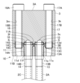
- FIG. FIG. 4 is a cross-sectional view of a flow path block and a joint structure.
- FIG. 1 is a perspective view of a fluid control device 1 and a plurality of pipes 2A to 2D according to an embodiment of the present disclosure.
- FIG. 2 is a perspective view of the flange 11 of the joint structure 10.
- FIG. 3 is a cross-sectional view of the flow passage block 3 and the joint structure 10. As shown in FIG.
- the fluid control device 1 comprises a flow path block 3, fluid control units 4A-4D, and a joint structure 10.
- the flow path block 3 has a generally rectangular parallelepiped shape and has an upper surface 3A and a lower surface 3B.
- the upper surface 3A is the surface located opposite the lower surface 3B.
- the fluid control units 4A-4D are disposed on the upper surface 3A of the flow path block 3.
- the interiors of the fluid control units 4A-4D are in communication with the first to sixth fluid passages 3c-3h, which will be described later.
- the fluid control units 4A-4D are, for example, valves, actuators, etc.
- the flow path block 3 is formed with the first to sixth fluid passages 3c to 3h.
- the first fluid passage 3c has one end opening to the lower surface 3B and the other end opening to the upper surface 3A where the fluid control unit 4A is located.
- the second fluid passage 3d has one end opening to the upper surface 3A where the fluid control unit 4A is located and the other end opening to the upper surface 3A where the fluid control unit 4B is located.
- the third fluid passage 3e has one end opening to the upper surface 3A where the fluid control unit 4B is located and the other end (not shown) opening to the lower surface 3B.
- the fourth fluid passage 3f has one end opening to the lower surface 3B and the other end opening to the upper surface 3A where the fluid control unit 4C is located.
- the fifth fluid passage 3g has one end opening to the upper surface 3A where the fluid control unit 4C is located and the other end opening to the upper surface 3A where the fluid control unit 4D is located.
- One end of the sixth fluid passage 3h opens into the portion of the upper surface 3A where the fluid control unit 4D is located, and the other end (not shown) opens into the lower surface 3B.
- a first annular recess 3i is formed around the opening of the first fluid passage 3c on the lower surface 3B of the flow passage block 3
- a second annular recess 3j is formed around the opening of the fourth fluid passage 3f.
- First and second bolt insertion holes 3k, 3m are formed at both ends of one side in the longitudinal direction of the flow passage block 3, penetrating from the upper surface 3A to the lower surface 3B.
- the joint structure 10 includes a flange 11, first and second sleeves 13 and 14, first and second gaskets 15 and 16, and first and second bolts 17 and 18.
- the flange 11 is in the shape of a roughly rectangular parallelepiped block and has an abutment surface 11A and a piping surface 11B.
- the abutment surface 11A abuts against the lower surface 3B of the flow path block 3.
- the piping surface 11B is the surface located opposite the abutment surface 11A.
- the flange 11 is formed with a first bolt screwing hole 11c, a second bolt screwing hole 11d, a first sleeve insertion hole 11e, and a second sleeve insertion hole 11f.
- the first and second sleeve insertion holes 11e and 11f are located between the first and second bolt screwing holes 11c and 11d.
- the first and second bolt screwing holes 11c, 11d and the first and second sleeve insertion holes 11e, 11f penetrate the flange 11 so as to open to the abutment surface 11A and the piping surface 11B.
- the first and second bolt screwing holes 11c, 11d have female threads on the abutment surface 11A side.
- the first and second bolt screwing holes 11c, 11d are countersunk holes with a large diameter portion on the abutment surface 11A side.
- the first and second sleeves 13, 14 are generally cylindrical, with the insides serving as fluid passages. These fluid passages are connected to the first fluid passage 3c and the fourth fluid passage 3f of the flow path block 3, respectively.
- the first and second sleeves 13, 14 are inserted into the first and second sleeve insertion holes 11e, 11f, respectively.
- the first and second sleeves 13 and 14 have large diameter portions 13A and 14A and small diameter portions 13B and 14B.
- the small diameter portions 13B and 14B are located below the large diameter portions 13A and 14A.
- Flange portions 13C and 14C are provided at the upper ends of the large diameter portions 13A and 14A.
- the flange portions 13C and 14C are inserted into the countersunk portions of the first and second sleeve insertion holes 11e and 11f.
- the upper surfaces of the flange portions 13C and 14C are formed with annular third and fourth recesses 13d and 14d.
- the lower ends of the large diameter portions 13A and 14A protrude downward from the piping surface 11B of the flange 11.
- the first and second gaskets 15, 16 are annular.
- the first gasket 15 is housed in the first recess 3i and the third recess 13d.
- the second gasket 16 is housed in the second recess 3j and the fourth recess 14d.
- the first and second gaskets 15, 16 seal between the first and fourth fluid passages 3c, 3f and the fluid passages of the first and second sleeves 13, 14 and the outside.
- the first and second bolts 17, 18 have heads 17A, 18A, shafts 17B, 18B, and male threads 17C, 18C.
- the heads 17A, 18A are formed with hexagonal holes.
- the shafts 17B, 18B extend downward from the heads 17A, 18A and are inserted into the first and second bolt insertion holes 3k, 3m.
- the male threads 17C, 18C are provided at the lower ends of the shafts 17B, 18B and are screwed into the first and second bolt screwing holes 11c, 11d.
- the first to fourth pipes 2A to 2D are connected to the fluid control device 1.
- the first pipe 2A extends in the vertical direction and is welded to the lower end of the first sleeve 13.
- the second pipe 2B is welded to the lower end of the first pipe 2A and extends in a direction perpendicular to the first pipe 2A.
- the third pipe 2C is welded to the lower end of the second sleeve 14.
- the upper part of the third pipe 2C extends in the vertical direction, and the lower part is bent relative to the upper part and inclined away from the first pipe 2A.
- the fourth pipe 2D is welded to the lower end of the third pipe 2C and extends in a direction perpendicular to the first pipe 2A.
- the second pipe 2B and the fourth pipe 2D are located on approximately the same plane.
- a method of connecting the pipes 2 to the flow path block 3 using the joint structure 10 will be described.
- the first sleeve 13 is inserted into the first sleeve insertion hole 11e of the flange 11, and the first pipe 2A is welded to the first sleeve 13.
- the second sleeve 14 is inserted into the second sleeve insertion hole 11f of the flange 11, and the third pipe 2C is welded to the second sleeve 14.
- the second pipe 2B is welded to the first pipe 2A.
- the fourth pipe 2D is welded to the third pipe 2C.
- the first sleeve 13, the first pipe 2A, and the second pipe 2B are lowered.
- the second pipe 2B and the fourth pipe 2D are welded one by one while being spaced apart from each other, so that the thermal effects of the welded parts can be suppressed.
- the first and second gaskets 15 and 16 are placed in the third and fourth recesses 13d and 14d of the first and second sleeves 13 and 14, and the abutment surface 11A of the flange 11 is brought close to the bottom surface 3B of the flow path block 3.
- the first and second bolts 17 and 18 are inserted into the first and second bolt insertion holes 3k and 3m from the top surface 3A side of the flow path block 3 and screwed into the first and second bolt screwing holes 11c and 11d of the flange 11 to crush the first and second gaskets 15 and 16.
- the flange 11 is fixed to the bottom surface 3B of the flow path block 3, and the pipes 2A to 2D are connected to the flow path block 3 by the joint structure 10.
- two first and second sleeves 13, 14 can be easily connected to a flow path block 3 in which multiple fluid passages are formed, using one flange 11 and two first and second bolts 17, 18. That is, according to the joint structure 10, the pipes 2A to 2D can be easily connected to a flow path block 3 in which multiple fluid passages are formed. Furthermore, compared to conventional joint structures, the joint structure 10 of this embodiment does not require space for construction on the underside 3B of the fluid control device 1, making it easier to install other pipes, fluid control devices, etc. Furthermore, compared to conventional joint structures, the joint structure 10 of this embodiment can reduce the number of parts, thereby reducing costs.
- first and second bolts 17, 18 are inserted into the first and second bolt insertion holes 3k, 3m from the top surface 3A of the flow path block 3 and screwed into the first and second bolt screwing holes 11c, 11d of the flange 11, thereby fixing the flange 11 to the bottom surface 3B of the flow path block 3. Therefore, the flange 11 can be fixed to the flow path block 3 from the top surface 3A side, improving the ease of assembly.
- the flange 11 has two first sleeve insertion holes 11e and two second sleeve insertion holes 11f between the first bolt screwing hole 11c and the second bolt screwing hole 11d, but three or more sleeve insertion holes may be formed and a sleeve may be inserted into each sleeve insertion hole.
- the flow path block 3 is not limited to the above embodiment, and the shape of the flow path block, the shape of the fluid passages, the position of the openings, etc. may be changed according to the number, function, and position of the fluid control units.
- Fluid control equipment 2A-2D 1st-4th pipes
- Flow path block 3A Top 3B: Bottom 3c-3h: 1st-6th fluid passages 11: Flange 11c: 1st bolt screwing hole 11d: 2nd bolt screwing hole 11e: 1st sleeve insertion hole 11f: 2nd sleeve insertion hole 13: 1st sleeve 14: 2nd sleeve 17: 1st bolt 18: 2nd bolt
Landscapes
- Engineering & Computer Science (AREA)
- General Engineering & Computer Science (AREA)
- Mechanical Engineering (AREA)
- Valve Housings (AREA)
- Flanged Joints, Insulating Joints, And Other Joints (AREA)
Abstract
Description
図2は、継手構造10のフランジ11の斜視図である。
図3は、流路ブロック3および継手構造10の断面図である。
Claims (2)
- 同一面に開口する複数の流体通路が形成された流路ブロックに、配管を接続するための継手構造であって、
第1ボルト螺合孔および第2ボルト螺合孔と、前記第1ボルト螺合孔および前記第2ボルト螺合孔の間に位置する第1スリーブ挿入孔および第2スリーブ挿入孔と、が形成されたフランジと、
内側が前記流路ブロックの流体通路と連通する流体通路となり、前記配管が接続され、前記フランジの前記第1スリーブ挿入孔および前記第2スリーブ挿入孔に挿入された第1スリーブおよび第2スリーブと、
前記流路ブロックに形成された第1ボルト挿通孔および第2ボルト挿通孔を介して前記フランジの前記第1ボルト螺合孔および前記第2ボルト螺合孔に螺合して、前記フランジを前記流路ブロックの前記同一面に固定する第1ボルトおよび第2ボルトと、を備える継手構造。 - 同一面に開口する複数の流体通路が形成された流路ブロックと、
第1ボルト螺合孔および第2ボルト螺合孔と、前記第1ボルト螺合孔および前記第2ボルト螺合孔の間に位置する第1スリーブ挿入孔および第2スリーブ挿入孔と、が形成され、前記同一面に当接するフランジと、
内側が前記流路ブロックの流体通路と連通する流体通路となり、配管が接続され、前記フランジの前記第1スリーブ挿入孔および前記第2スリーブ挿入孔に挿入された第1スリーブおよび第2スリーブと、
前記流路ブロックに形成された第1ボルト挿通孔および第2ボルト挿通孔を介して前記フランジの前記第1ボルト螺合孔および前記第2ボルト螺合孔に螺合して、前記フランジを前記流路ブロックの前記同一面に固定する第1ボルトおよび第2ボルトと、を備える流体制御機器。
Priority Applications (3)
| Application Number | Priority Date | Filing Date | Title |
|---|---|---|---|
| KR1020257042828A KR20260013985A (ko) | 2023-05-29 | 2024-04-05 | 조인트 구조 및 유체 제어 기기 |
| JP2025523310A JPWO2024247488A1 (ja) | 2023-05-29 | 2024-04-05 | |
| US19/401,691 US20260078849A1 (en) | 2023-05-29 | 2025-11-26 | Joint structure and fluid control device |
Applications Claiming Priority (2)
| Application Number | Priority Date | Filing Date | Title |
|---|---|---|---|
| JP2023-087977 | 2023-05-29 | ||
| JP2023087977 | 2023-05-29 |
Related Child Applications (1)
| Application Number | Title | Priority Date | Filing Date |
|---|---|---|---|
| US19/401,691 Continuation US20260078849A1 (en) | 2023-05-29 | 2025-11-26 | Joint structure and fluid control device |
Publications (1)
| Publication Number | Publication Date |
|---|---|
| WO2024247488A1 true WO2024247488A1 (ja) | 2024-12-05 |
Family
ID=93657709
Family Applications (1)
| Application Number | Title | Priority Date | Filing Date |
|---|---|---|---|
| PCT/JP2024/014049 Ceased WO2024247488A1 (ja) | 2023-05-29 | 2024-04-05 | 継手構造および流体制御機器 |
Country Status (5)
| Country | Link |
|---|---|
| US (1) | US20260078849A1 (ja) |
| JP (1) | JPWO2024247488A1 (ja) |
| KR (1) | KR20260013985A (ja) |
| TW (1) | TW202449315A (ja) |
| WO (1) | WO2024247488A1 (ja) |
Citations (7)
| Publication number | Priority date | Publication date | Assignee | Title |
|---|---|---|---|---|
| JPS49103013U (ja) * | 1972-12-25 | 1974-09-04 | ||
| JPS62127709U (ja) * | 1986-02-06 | 1987-08-13 | ||
| JPH10169859A (ja) * | 1996-12-03 | 1998-06-26 | Benkan Corp | 集積化ガスパネルの制御機器取付用シールガスケット |
| JP2005090576A (ja) * | 2003-09-16 | 2005-04-07 | Koganei Corp | 空気圧配管継手ユニット |
| JP2007321833A (ja) * | 2006-05-31 | 2007-12-13 | Hitachi Metals Ltd | ガス供給機器用流路ブロックおよび半導体製造用ガス供給ユニット |
| WO2013042573A1 (ja) * | 2011-09-22 | 2013-03-28 | 株式会社フジキン | 継手 |
| JP2015178894A (ja) * | 2013-12-05 | 2015-10-08 | Ckd株式会社 | 配管継手、流体供給制御装置、及び配管接続構造 |
-
2024
- 2024-04-05 WO PCT/JP2024/014049 patent/WO2024247488A1/ja not_active Ceased
- 2024-04-05 JP JP2025523310A patent/JPWO2024247488A1/ja active Pending
- 2024-04-05 KR KR1020257042828A patent/KR20260013985A/ko active Pending
- 2024-04-17 TW TW113114277A patent/TW202449315A/zh unknown
-
2025
- 2025-11-26 US US19/401,691 patent/US20260078849A1/en active Pending
Patent Citations (7)
| Publication number | Priority date | Publication date | Assignee | Title |
|---|---|---|---|---|
| JPS49103013U (ja) * | 1972-12-25 | 1974-09-04 | ||
| JPS62127709U (ja) * | 1986-02-06 | 1987-08-13 | ||
| JPH10169859A (ja) * | 1996-12-03 | 1998-06-26 | Benkan Corp | 集積化ガスパネルの制御機器取付用シールガスケット |
| JP2005090576A (ja) * | 2003-09-16 | 2005-04-07 | Koganei Corp | 空気圧配管継手ユニット |
| JP2007321833A (ja) * | 2006-05-31 | 2007-12-13 | Hitachi Metals Ltd | ガス供給機器用流路ブロックおよび半導体製造用ガス供給ユニット |
| WO2013042573A1 (ja) * | 2011-09-22 | 2013-03-28 | 株式会社フジキン | 継手 |
| JP2015178894A (ja) * | 2013-12-05 | 2015-10-08 | Ckd株式会社 | 配管継手、流体供給制御装置、及び配管接続構造 |
Also Published As
| Publication number | Publication date |
|---|---|
| JPWO2024247488A1 (ja) | 2024-12-05 |
| US20260078849A1 (en) | 2026-03-19 |
| TW202449315A (zh) | 2024-12-16 |
| KR20260013985A (ko) | 2026-01-29 |
Similar Documents
| Publication | Publication Date | Title |
|---|---|---|
| CA1207658A (en) | Marine riser coupling assembly | |
| US11905811B2 (en) | Fluid conduit connector system | |
| US11852267B2 (en) | Fluid conduit connector system | |
| US11384876B2 (en) | Fluid conduit connector system | |
| US7021392B2 (en) | Body with couplings | |
| KR20010083048A (ko) | 통합된 모듈식 화학물질 전달 블럭 | |
| JP2020523502A (ja) | 圧縮抵抗ねじ接続部 | |
| US5997045A (en) | Pipe joint | |
| WO2024247488A1 (ja) | 継手構造および流体制御機器 | |
| JP6057233B1 (ja) | 配管継手、溶接方法、高圧ガス用装置の製造方法および高圧ガス用装置 | |
| JP4997157B2 (ja) | 流体制御装置 | |
| CN217740929U (zh) | 一种便于电磁阀接头组装的工装 | |
| JP2017187167A (ja) | 高圧ガス用配管、配管継手、溶接方法、高圧ガス用装置の製造方法および高圧ガス用装置 | |
| JPH041422Y2 (ja) | ||
| JP2005127401A (ja) | 配管用金具の結合ボルト | |
| CN115596744B (zh) | 用于浮体拼组的连接组件及浮体拼组的连接方法 | |
| US20250283562A1 (en) | Joint structure | |
| KR200464849Y1 (ko) | 맞춤형 벌크헤드 유니온 | |
| JP2001027342A (ja) | バルブ | |
| CN214093485U (zh) | 用于测试管路气密性的管路接头 | |
| KR200429819Y1 (ko) | 파이프 연결구 | |
| US20240288102A1 (en) | Pipe | |
| KR200216870Y1 (ko) | 이경관이음용 볼밸브 | |
| JPH0637691U (ja) | 配管用継手 | |
| KR200261422Y1 (ko) | 파이프 연결장치 |
Legal Events
| Date | Code | Title | Description |
|---|---|---|---|
| 121 | Ep: the epo has been informed by wipo that ep was designated in this application |
Ref document number: 24814975 Country of ref document: EP Kind code of ref document: A1 |
|
| ENP | Entry into the national phase |
Ref document number: 2025523310 Country of ref document: JP Kind code of ref document: A |
|
| ENP | Entry into the national phase |
Ref document number: 1020257042828 Country of ref document: KR Free format text: ST27 STATUS EVENT CODE: A-0-1-A10-A15-NAP-PA0105 (AS PROVIDED BY THE NATIONAL OFFICE) |
|
| WWE | Wipo information: entry into national phase |
Ref document number: 1020257042828 Country of ref document: KR |
|
| NENP | Non-entry into the national phase |
Ref country code: DE |
|
| WWP | Wipo information: published in national office |
Ref document number: 1020257042828 Country of ref document: KR |