WO2024247440A1 - ベルト式研削工具 - Google Patents
ベルト式研削工具 Download PDFInfo
- Publication number
- WO2024247440A1 WO2024247440A1 PCT/JP2024/009714 JP2024009714W WO2024247440A1 WO 2024247440 A1 WO2024247440 A1 WO 2024247440A1 JP 2024009714 W JP2024009714 W JP 2024009714W WO 2024247440 A1 WO2024247440 A1 WO 2024247440A1
- Authority
- WO
- WIPO (PCT)
- Prior art keywords
- belt
- tension bar
- endless
- grinding
- drive
- Prior art date
- Legal status (The legal status is an assumption and is not a legal conclusion. Google has not performed a legal analysis and makes no representation as to the accuracy of the status listed.)
- Ceased
Links
Images



Classifications
-
- B—PERFORMING OPERATIONS; TRANSPORTING
- B23—MACHINE TOOLS; METAL-WORKING NOT OTHERWISE PROVIDED FOR
- B23Q—DETAILS, COMPONENTS, OR ACCESSORIES FOR MACHINE TOOLS, e.g. ARRANGEMENTS FOR COPYING OR CONTROLLING; MACHINE TOOLS IN GENERAL CHARACTERISED BY THE CONSTRUCTION OF PARTICULAR DETAILS OR COMPONENTS; COMBINATIONS OR ASSOCIATIONS OF METAL-WORKING MACHINES, NOT DIRECTED TO A PARTICULAR RESULT
- B23Q17/00—Arrangements for observing, indicating or measuring on machine tools
- B23Q17/09—Arrangements for observing, indicating or measuring on machine tools for indicating or measuring cutting pressure or for determining cutting-tool condition, e.g. cutting ability, load on tool
-
- B—PERFORMING OPERATIONS; TRANSPORTING
- B24—GRINDING; POLISHING
- B24B—MACHINES, DEVICES, OR PROCESSES FOR GRINDING OR POLISHING; DRESSING OR CONDITIONING OF ABRADING SURFACES; FEEDING OF GRINDING, POLISHING, OR LAPPING AGENTS
- B24B21/00—Machines or devices using grinding or polishing belts; Accessories therefor
-
- B—PERFORMING OPERATIONS; TRANSPORTING
- B24—GRINDING; POLISHING
- B24B—MACHINES, DEVICES, OR PROCESSES FOR GRINDING OR POLISHING; DRESSING OR CONDITIONING OF ABRADING SURFACES; FEEDING OF GRINDING, POLISHING, OR LAPPING AGENTS
- B24B21/00—Machines or devices using grinding or polishing belts; Accessories therefor
- B24B21/18—Accessories
-
- B—PERFORMING OPERATIONS; TRANSPORTING
- B24—GRINDING; POLISHING
- B24B—MACHINES, DEVICES, OR PROCESSES FOR GRINDING OR POLISHING; DRESSING OR CONDITIONING OF ABRADING SURFACES; FEEDING OF GRINDING, POLISHING, OR LAPPING AGENTS
- B24B49/00—Measuring or gauging equipment for controlling the feed movement of the grinding tool or work; Arrangements of indicating or measuring equipment, e.g. for indicating the start of the grinding operation
- B24B49/10—Measuring or gauging equipment for controlling the feed movement of the grinding tool or work; Arrangements of indicating or measuring equipment, e.g. for indicating the start of the grinding operation involving electrical means
Definitions
- the present invention relates to a belt-type grinding tool that performs grinding work by rotating an endless grinding belt that is wound between a drive pulley and an idle pulley.
- a belt-type grinding tool is a grinding tool that has a drive pulley that is rotated by a drive unit such as an air motor or electric motor, and an idle pulley that is attached so that it can rotate freely.
- the endless grinding belt that is looped between the drive pulley and the idle pulley is rotated by the rotation of the drive pulley and brought into contact with the workpiece to be processed, thereby grinding the workpiece (Patent Document 1).
- the endless grinding belt gradually wears out as a result of processing work, so it is usually replaced with a new endless grinding belt after a certain amount of use.
- the lifespan of an endless grinding belt varies depending on various processing conditions, such as the material and shape of the workpiece, the pressing force of the belt against the workpiece, and the rotation speed of the belt.
- the lifespan also differs depending on the individual differences of the endless grinding belt itself. Therefore, the wear of the endless grinding belt progresses faster than expected, and it is possible that the endless grinding belt will break during grinding work.
- Belt-type grinding tools are sometimes mounted on automatic machines such as robots and used under automatic control, but in such cases, since the operator is not necessarily near the belt-type grinding tool, it is not possible to immediately recognize that the endless grinding belt has broken, and the automatic machine may continue to operate as is. Even in the case of a handheld belt-type grinding tool, it may be preferable to notify a manager or external device in a remote location as soon as possible.
- the present invention aims to provide a belt-type grinding tool that automatically detects when an endless grinding belt breaks.
- the present invention provides: A tool body, A drive unit disposed in the tool body; A drive pulley that is rotationally driven by the drive unit; an idler pulley rotatably attached to the tool body; a belt breakage detection means for automatically detecting a breakage of the endless grinding belt wound between the drive pulley and the idle pulley;
- a belt type grinding tool comprising:
- the belt-type grinding tool is equipped with a belt breakage detection means that automatically detects breakage of the endless grinding belt, making it possible to notify a person or external device in a remote location that the endless grinding belt has broken, so that the necessary measures can be taken promptly.
- the tool body comprises a base portion to which the drive portion is attached, a tension bar which rotatably holds the idle pulley and is held displaceable between a front position and a rear position with respect to the base portion, and a biasing member which is set between the tension bar and the base portion and biases the tension bar toward the front position, and when the endless grinding belt is fitted around the drive pulley and the idle pulley, the tension bar is positioned at an intermediate position between the front position and the rear position,
- the belt breakage detection means may detect that the tension bar has been displaced to the forward position.
- the belt breakage detection means is a switch attached to the base portion, The switch may be pressed by the tension bar when the tension bar is in the forward position.
- the switch is a plunger switch having a housing fixed to the base portion and a contact arranged at a tip of the housing,
- the tension bar has a groove extending in the front-rear direction, When the tension bar is in the intermediate position, the contact is located in the groove, and when the tension bar is displaced from the intermediate position to the forward position, the contact is released from the groove and pushed into the housing by the tension bar.
- the drive unit is an electric motor
- the belt breakage detection means may be configured to measure the current flowing through the electric motor and determine that the endless grinding belt has broken when the current drops below a predetermined threshold value while the electric motor is running.
- the device may further include a signal output unit for outputting a predetermined signal to the outside when the belt breakage detection means detects a break in the endless grinding belt.
- the device may further include a calculation unit that calculates an accumulated drive time by accumulating the drive time of the drive unit in a specified state, sets a recommended replacement time based on the accumulated drive time when a break in the endless grinding belt is detected by the belt break detection means, resets the accumulated drive time, and transmits a specified notification signal when the newly calculated accumulated drive time after replacement of the endless grinding belt is equal to or greater than the recommended replacement time.
- a calculation unit that calculates an accumulated drive time by accumulating the drive time of the drive unit in a specified state, sets a recommended replacement time based on the accumulated drive time when a break in the endless grinding belt is detected by the belt break detection means, resets the accumulated drive time, and transmits a specified notification signal when the newly calculated accumulated drive time after replacement of the endless grinding belt is equal to or greater than the recommended replacement time.
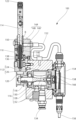
- FIG. 1 is a cross-sectional view of a belt-type grinding tool according to an embodiment of the present invention.
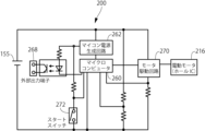
- FIG. 2 is a functional block diagram of the belt grinding tool of FIG. 1 .
- FIG. 2 is a diagram showing a state in which an endless grinding belt is attached to the belt-type grinding tool of FIG. 1 .
- FIG. 4 is an enlarged view of part A in FIG. 3 .
- 4 is a diagram showing a state in which the endless grinding belt of the belt-type grinding tool of FIG. 3 is broken.
- FIG. 6 is an enlarged view of part B in FIG. 5 .
- FIG. 4 is a functional block diagram of a belt-type grinding tool according to another embodiment of the present invention.
- the belt type grinding tool 100 comprises a tool body 110 having a base portion 112 and a tension bar 114, an air motor (drive portion) 116 disposed on the base portion 112 of the tool body 110, a drive pulley 120 attached to a rotating shaft 118 of the air motor 116, and an idle pulley 122 rotatably attached to the tension bar 114 of the tool body 110.
- the base portion 112 is made up of a first portion 124 that holds the tension bar 114, and a second portion 126 that holds the air motor 116.
- the belt type grinding tool 100 according to this embodiment is configured to be attached to an automated machine such as a robot for use.
- the air motor 116 comprises a motor case 128, a rotor 130 rotatably mounted within the motor case 128, and a number of vanes 132 arranged so as to be displaceable radially relative to the rotor 130.
- the air motor 116 is driven to rotate by compressed air supplied via a tube (not shown) connected to a tube connection fitting 134 attached to the base portion 112. More specifically, a rotational force is generated in the rotor 130 when the compressed air hits the vanes 132 protruding radially outward from the rotor 130, causing the rotor 130 to be driven to rotate.
- the rotating shaft 118 is formed integrally with the rotor 130 and rotates together with the rotor 130.
- the tension bar 114 is held so as to be displaceable in the front-rear direction (up-down direction as viewed in the figure) between a rear position (FIG. 1) and a front position (FIG. 5) relative to the base portion 112.
- the tool body 110 further has a spring (biasing member) 136 set between the tension bar 114 and the base portion 112, and the tension bar 114 is biased toward the front position by this spring 136.
- the tool body 110 further has a locking member 138 arranged so as to be displaceable in the lateral direction (left-right direction as viewed in the figure).
- the tension bar 114 is locked in the rear position by a locking protrusion 142 of the locking member 138 engaging with a locking recess 140 formed on the side surface 114a of the tension bar 114.
- the belt-type grinding tool 100 further includes a plunger switch (belt breakage detection means) 144 attached to the base 112 of the tool body 110.
- the plunger switch 144 has a housing 146 fixed to the base 112 and a spherical contact 148 arranged at its tip, and is configured to be turned on when the contact 148 is pressed into the housing 146.
- the tension bar 114 is in the rear position in FIG. 1, the contact 148 of the plunger switch 144 is in a groove 150 formed in the side surface 114a of the tension bar 114 and is not pressed into the housing 146. At this time, the plunger switch 144 is in the OFF state.
- a wiring 152 extending from the rear end of the housing 146 of the plunger switch 144 is connected to a circuit housing 154 fixed to the base 112.
- a wiring 156 for supplying power from an external power source 155 (FIG. 2) and outputting a signal to an external device is also connected to the circuit housing 154.
- the circuit board 158 disposed within the circuit housing 154 is provided with a microcomputer (arithmetic unit) 160, a microcomputer power generation circuit 162, and a Hall IC 164.
- the microcomputer power generation circuit 162 converts the voltage supplied from the external power supply 155 into a voltage suitable for the microcomputer 160 (e.g., 3.3 V).
- the Hall IC 164 is disposed so as to detect the magnetic field of a magnet 166 attached to the rear end of the air motor 116. Since the magnet 166 rotates together with the rotor 130 of the air motor 116, the magnetic field detected by the Hall IC 164 changes periodically while the air motor 116 is rotating.
- the microcomputer 160 can determine the rotational speed of the air motor 116 from the periodic change in the magnetic field detected by the Hall IC 164.
- the endless grinding belt B When the endless grinding belt B is attached, the endless grinding belt B is placed around the drive pulley 120 and the idle pulley 122 with the tension bar 114 in the rear position, and the locking member 138 is pushed in. When the locking member 138 is pushed in, the locking protrusion 142 of the locking member 138 is disengaged from the locking recess 140 of the tension bar 114, and the tension bar 114 is displaced forward by the biasing force of the spring 136. As a result, as shown in FIG. 3, the endless grinding belt B is attached around the drive pulley 120 and the idle pulley 122. At this time, the tension bar 114 has not been displaced to the front position (FIG. 5), but is in an intermediate position between the front position and the rear position. When compressed air is supplied from the tube connection joint 134, the air motor 116 rotates, which in turn rotates the drive pulley 120, driving the endless grinding belt B to rotate. Grinding work can be performed by pressing the rotating endless grinding belt B against the workpiece.
- the air motor 116 rotates when compressed air hits the vanes 132 that protrude radially outward from the rotor 130. If the vanes 132 are retracted into the rotor 130, the rotor 130 does not generate sufficient rotational force, and the rotor 130 does not rotate or does not rotate at a sufficient speed, which may cause the air motor 116 to fail to start. In the belt-type grinding tool 100, the rotational speed of the air motor 116 is detected by the above-mentioned Hall IC 164, and if the air motor 116 is not rotating at a sufficient speed despite the supply of compressed air, a signal indicating a failure to start is sent to the outside.
- the microcomputer 160 determines the rotational speed of the air motor 116 based on the output from the Hall IC 164, and if the rotational speed is below a predetermined threshold (e.g., 500 rpm), a predetermined signal is sent from the external output terminal 168 to the outside.
- a predetermined threshold e.g. 500 rpm
- the external device can perform a return operation of the air motor 116.
- the return operation is an operation in which the vane 132 is projected from the rotor 130 to allow the air motor 116 to rotate normally.
- the microcomputer 160 detects that the plunger switch 144 has been turned on, it transmits a predetermined signal from the external output terminal (signal output unit) 168 to the outside to notify that a break in the endless grinding belt B has been detected.
- an external device such as an automatic machine to which the belt-type grinding tool 100 is attached receives a signal notifying that the endless grinding belt B has broken, it can stop the air motor 116 to stop the grinding operation, or display a message to notify those around it. It can also be configured to perform an operation to install a new endless grinding belt B.
Landscapes
- Engineering & Computer Science (AREA)
- Mechanical Engineering (AREA)
- Finish Polishing, Edge Sharpening, And Grinding By Specific Grinding Devices (AREA)
- Constituent Portions Of Griding Lathes, Driving, Sensing And Control (AREA)
Priority Applications (1)
| Application Number | Priority Date | Filing Date | Title |
|---|---|---|---|
| JP2025523287A JPWO2024247440A1 (https=) | 2023-05-26 | 2024-03-13 |
Applications Claiming Priority (2)
| Application Number | Priority Date | Filing Date | Title |
|---|---|---|---|
| JP2023086912 | 2023-05-26 | ||
| JP2023-086912 | 2023-05-26 |
Publications (1)
| Publication Number | Publication Date |
|---|---|
| WO2024247440A1 true WO2024247440A1 (ja) | 2024-12-05 |
Family
ID=93657078
Family Applications (1)
| Application Number | Title | Priority Date | Filing Date |
|---|---|---|---|
| PCT/JP2024/009714 Ceased WO2024247440A1 (ja) | 2023-05-26 | 2024-03-13 | ベルト式研削工具 |
Country Status (3)
| Country | Link |
|---|---|
| JP (1) | JPWO2024247440A1 (https=) |
| TW (1) | TWI897306B (https=) |
| WO (1) | WO2024247440A1 (https=) |
Citations (9)
| Publication number | Priority date | Publication date | Assignee | Title |
|---|---|---|---|---|
| JPS508584U (https=) * | 1973-05-19 | 1975-01-29 | ||
| US4267671A (en) * | 1978-08-24 | 1981-05-19 | Contraves Goerz Corporation | Positioning of an abrasive belt on a grinding machine |
| US4635405A (en) * | 1983-05-18 | 1987-01-13 | Timesavers, Inc. | Continuous arcuate feed assembly |
| US20170057038A1 (en) * | 2015-09-01 | 2017-03-02 | Jpw Industries Inc. | Power tool with digital variable reluctance motor control |
| KR101715187B1 (ko) * | 2016-07-29 | 2017-03-10 | 박재성 | 전류 신호 분석을 이용한 제철용 연삭기 고장 진단 장치 및 방법 |
| US20180056474A1 (en) * | 2016-08-23 | 2018-03-01 | Techway Industrial Co., Ltd. | Hand-Held Belt Sander |
| JP2021074874A (ja) * | 2019-11-11 | 2021-05-20 | 株式会社マキタ | ベルトサンダ |
| KR20210103112A (ko) * | 2020-02-13 | 2021-08-23 | 두산공작기계 주식회사 | 공작기계용 벨트구동 파단 감지장치 및 감지방법 |
| JP2022000324A (ja) * | 2020-06-18 | 2022-01-04 | コイロ ベズィッツ ゲゼルシャフト ミット ベシュレンクテル ハフツング ウント コンパニー エーデーファウ−ディーンストライストゥングス コマンデイトゲゼルシャフト | 鋸ベルトの残余寿命を予測する方法およびベルト鋸機 |
Family Cites Families (3)
| Publication number | Priority date | Publication date | Assignee | Title |
|---|---|---|---|---|
| US8512096B2 (en) * | 2007-12-07 | 2013-08-20 | General Electric Company | System for removing material from components |
| US20200030938A1 (en) * | 2017-02-28 | 2020-01-30 | 3M Innovative Properties Company | Abrasive product for communication with abrading tool |
| TWM574539U (zh) * | 2018-10-25 | 2019-02-21 | 鼎隆工業股份有限公司 | 可更換砂帶的砂帶機 |
-
2024
- 2024-03-13 JP JP2025523287A patent/JPWO2024247440A1/ja active Pending
- 2024-03-13 WO PCT/JP2024/009714 patent/WO2024247440A1/ja not_active Ceased
- 2024-03-21 TW TW113110469A patent/TWI897306B/zh active
Patent Citations (9)
| Publication number | Priority date | Publication date | Assignee | Title |
|---|---|---|---|---|
| JPS508584U (https=) * | 1973-05-19 | 1975-01-29 | ||
| US4267671A (en) * | 1978-08-24 | 1981-05-19 | Contraves Goerz Corporation | Positioning of an abrasive belt on a grinding machine |
| US4635405A (en) * | 1983-05-18 | 1987-01-13 | Timesavers, Inc. | Continuous arcuate feed assembly |
| US20170057038A1 (en) * | 2015-09-01 | 2017-03-02 | Jpw Industries Inc. | Power tool with digital variable reluctance motor control |
| KR101715187B1 (ko) * | 2016-07-29 | 2017-03-10 | 박재성 | 전류 신호 분석을 이용한 제철용 연삭기 고장 진단 장치 및 방법 |
| US20180056474A1 (en) * | 2016-08-23 | 2018-03-01 | Techway Industrial Co., Ltd. | Hand-Held Belt Sander |
| JP2021074874A (ja) * | 2019-11-11 | 2021-05-20 | 株式会社マキタ | ベルトサンダ |
| KR20210103112A (ko) * | 2020-02-13 | 2021-08-23 | 두산공작기계 주식회사 | 공작기계용 벨트구동 파단 감지장치 및 감지방법 |
| JP2022000324A (ja) * | 2020-06-18 | 2022-01-04 | コイロ ベズィッツ ゲゼルシャフト ミット ベシュレンクテル ハフツング ウント コンパニー エーデーファウ−ディーンストライストゥングス コマンデイトゲゼルシャフト | 鋸ベルトの残余寿命を予測する方法およびベルト鋸機 |
Also Published As
| Publication number | Publication date |
|---|---|
| TW202446542A (zh) | 2024-12-01 |
| JPWO2024247440A1 (https=) | 2024-12-05 |
| TWI897306B (zh) | 2025-09-11 |
Similar Documents
| Publication | Publication Date | Title |
|---|---|---|
| US11491616B2 (en) | Power tools with user-selectable operational modes | |
| JP4906236B2 (ja) | 締付工具 | |
| JP6709129B2 (ja) | 電動工具 | |
| US6565293B2 (en) | Pneumatic machine tool | |
| JP4493324B2 (ja) | 車両用発電機のブラシ摩耗検出装置 | |
| JP5618257B2 (ja) | 電動工具 | |
| EP3302882B1 (en) | Power tools with user-selectable operational modes | |
| KR20190050739A (ko) | 로봇 제어 장치 및 이 제어 장치를 구비한 로봇 | |
| WO2024247440A1 (ja) | ベルト式研削工具 | |
| TWI908006B (zh) | 可搬動型動力工具 | |
| JP2003248519A (ja) | 電気機器の温度に依存した電力制御のための方法および装置 | |
| JP4103367B2 (ja) | ワイヤレスセンサ及びセンサ付軸受装置 | |
| CN1985039B (zh) | 用于检验一种织机的片梭驱动轮的方法、片梭驱动轮和片梭织机 | |
| JP6442223B2 (ja) | 作業機 | |
| JP2012130989A (ja) | 回転工具 | |
| JP2011218468A (ja) | ワイヤソーのガイドプーリ磨耗検出装置及び磨耗検出方法 | |
| WO2025017975A1 (ja) | 可搬型電動工具 | |
| JP6442222B2 (ja) | 作業機 | |
| JP2009503962A (ja) | 動かされる機械部品用のポーリングシステム | |
| US20200153365A1 (en) | Electric motor having function of checking energized state of brake | |
| KR101547772B1 (ko) | 용접용 와이어 송급 장치 | |
| JP2004308692A (ja) | 動力伝達機構の緩み監視装置および同装置を備えた動力機器 | |
| KR20070037134A (ko) | 용접팁 연마장치의 제어방법 | |
| KR100627457B1 (ko) | 콘베이어벨트의 구동풀리 검지장치 | |
| KR101443088B1 (ko) | 비상스위치 장치 |
Legal Events
| Date | Code | Title | Description |
|---|---|---|---|
| 121 | Ep: the epo has been informed by wipo that ep was designated in this application |
Ref document number: 24814927 Country of ref document: EP Kind code of ref document: A1 |
|
| WWE | Wipo information: entry into national phase |
Ref document number: 2025523287 Country of ref document: JP |
|
| NENP | Non-entry into the national phase |
Ref country code: DE |