WO2024247167A1 - 加熱システム - Google Patents
加熱システム Download PDFInfo
- Publication number
- WO2024247167A1 WO2024247167A1 PCT/JP2023/020294 JP2023020294W WO2024247167A1 WO 2024247167 A1 WO2024247167 A1 WO 2024247167A1 JP 2023020294 W JP2023020294 W JP 2023020294W WO 2024247167 A1 WO2024247167 A1 WO 2024247167A1
- Authority
- WO
- WIPO (PCT)
- Prior art keywords
- thermal image
- human detection
- unit
- detection area
- heating
- Prior art date
- Legal status (The legal status is an assumption and is not a legal conclusion. Google has not performed a legal analysis and makes no representation as to the accuracy of the status listed.)
- Ceased
Links
Images










Classifications
-
- F—MECHANICAL ENGINEERING; LIGHTING; HEATING; WEAPONS; BLASTING
- F24—HEATING; RANGES; VENTILATING
- F24C—DOMESTIC STOVES OR RANGES ; DETAILS OF DOMESTIC STOVES OR RANGES, OF GENERAL APPLICATION
- F24C3/00—Stoves or ranges for gaseous fuels
- F24C3/12—Arrangement or mounting of control or safety devices
-
- G—PHYSICS
- G06—COMPUTING OR CALCULATING; COUNTING
- G06T—IMAGE DATA PROCESSING OR GENERATION, IN GENERAL
- G06T1/00—General purpose image data processing
Definitions
- This disclosure relates to a heating system with a safety device.
- AI-based detection methods are used to detect people on thermal images.
- safety devices using infrared imaging devices are required to operate independently without connecting to external PCs or servers. Therefore, using a high-performance CPU to operate the AI raises the problem of higher product prices and shorter battery life due to increased power consumption.
- MCUs microcontroller units
- the processing power of the MCU is limited, the number of bits of the thermal image input to the MCU needs to be low. For example, an image taken with an infrared camera may be converted into an 8-bit, 256-level grayscale image, and AI-based human detection processing may be performed on the MCU.
- the temperature resolution of 1 digit which is the unit of digital signals, decreases in thermal images with a reduced number of bits. This causes the difference between the background temperature and the brightness of the person to become extremely small, making it difficult to determine whether a person is present or not on the thermal image.
- This disclosure has been made to solve the problems described above, and its purpose is to obtain a heating system that can accurately detect people in a thermal image even when a high-temperature subject is present within the imaging range of the infrared imaging device.
- the first heating system includes a heating device having a heating section for heating an object to be heated, and a safety device for controlling the heating device, and the safety device includes an infrared imaging device that includes a person standing in front of the heating device, the heating section, and the object to be heated within its imaging range, a thermal image generating section that generates a thermal image from an output signal from the infrared imaging device, a human detection section that detects whether a person is present in the thermal image, a human detection area setting section that sets a human detection area that is an area in the thermal image where a person is detected, and a sensitivity adjustment section that adjusts the sensitivity of each pixel of the infrared imaging device, and the sensitivity adjustment section is characterized in that the sensitivity of the pixels corresponding to the human detection area is set higher than that of pixels corresponding to other areas.
- the second heating system includes a heating device having a heating section for heating an object to be heated, and a safety device for controlling the heating device, and the safety device includes an infrared imaging device that includes a person standing in front of the heating device, the heating section, and the object to be heated within its imaging range, a thermal image generating section that generates a thermal image from an output signal from the infrared imaging device, a human detection section that detects whether a person is present in the thermal image, and a protective member that is disposed in front of an infrared-transmitting lens of the infrared imaging device and transmits infrared rays, and is characterized in that the thickness of the protective member in an area corresponding to a human detection area, which is an area in the thermal image where a person is detected, is thinner than the thickness of the protective member in an area corresponding to the outside of the human detection area.
- the third heating system includes a heating device having a heating unit that heats an object to be heated, and a safety device that controls the heating device, and the safety device includes an infrared imaging device that includes a person standing in front of the heating device, the heating unit, and the object to be heated in its imaging range, a thermal image generation unit that generates a thermal image from an output signal of the infrared imaging device, a human detection unit that detects whether a person is present in the thermal image, a human detection area setting unit that sets a human detection area that is an area in the thermal image where a person is detected, and a sensitivity adjustment unit that switches the sensitivity of the entire pixels of the infrared imaging device for each frame of an image continuously captured by the infrared imaging device, and the continuously captured images include a first frame and a second frame in which the sensitivity of the entire pixels is lower than that of the first frame, and the thermal image generation unit generates the thermal image using the first frame for the human detection area and the second frame for other areas.
- the sensitivity of pixels corresponding to the human detection area is set higher than the sensitivity of pixels corresponding to other areas. This makes it possible to simultaneously display the high-temperature subject and the person on the thermal image using an inexpensive MCU, even if there is a high-temperature subject within the imaging range of the infrared imaging device, and therefore makes it possible to accurately detect the person on the thermal image.
- the thickness of the protective member in the area corresponding to the human detection area is thinner than the thickness of the protective member in the area corresponding to the outside of the human detection area. This makes it possible to reduce the infrared transmittance in the area corresponding to the outside of the human detection area. Therefore, even if a high-temperature subject is present within the imaging range of the infrared imaging device, it is possible to simultaneously display the high-temperature subject and the person on the thermal image using an inexpensive MCU, thereby making it possible to accurately detect the person on the thermal image.
- the sensitivity of the entire pixels of the infrared imaging device is switched for each frame of continuously captured images, and a thermal image is generated using a first frame with high sensitivity for the human detection area and a second frame with low sensitivity for other areas.
- FIG. 1 is a side view showing a heating system according to a first embodiment.
- FIG. 1 is a block diagram showing a heating system according to a first embodiment.
- 1 is a diagram showing an infrared imaging device according to a first embodiment;
- FIG. 13 is a flowchart for setting a human detection area and sensitivity.
- FIG. 13 is a diagram showing an image of sensitivity settings of an infrared imaging device. This is a thermal image taken without adjusting the sensitivity of the human detection area. This is a thermal image taken without adjusting the sensitivity of the human detection area. This is a thermal image taken with the sensitivity of the human detection area adjusted.
- 13 is a flowchart of human detection.
- FIG. 11 is a diagram showing an infrared imaging device according to a second embodiment.
- FIG. 11 is a block diagram showing a heating system according to a second embodiment.
- 10 is a flowchart showing the operation of a safety device according to a second embodiment.
- FIG. 13 is a diagram showing a thermal image before offset.
- FIG. 13 is a diagram showing a thermal image after offset.
- 13 is a flowchart showing the operation of a safety device according to a third embodiment.
- FIG. 13 is a diagram showing a part of a safety device according to a fourth embodiment.
- FIG. 1 shows a first frame with high sensitivity.
- FIG. 13 shows a second frame with low sensitivity.
- 13A and 13B are diagrams showing thermal images generated by a thermal image generating unit according to embodiment 5.
- Embodiment 1. 1 is a side view showing a heating system according to embodiment 1.
- a heating device 1 is a cooking utensil or the like used by a person 2, and heats an object to be heated 3.
- a safety device 4 controls the heating device 1.
- FIG. 2 is a block diagram showing the heating system according to the first embodiment.
- the heating section 5 of the heating device 1 heats the object 3 to be heated.
- the operation section 6 inputs operations from the person 2.
- the memory section 7 of the heating device 1 stores recipe information such as a heating sequence.
- the control section 8 controls the heating section 5 according to instructions from the operation section 6 or the recipe information stored in the memory section 7. Examples of recipe information include simmering for 10 minutes after the water temperature reaches 100 degrees, frying for 3 minutes at a frying pan temperature of 160 degrees, etc.
- the safety device 4 has an infrared imaging device 9 that captures an image of a subject.
- the safety device 4 is installed above the heating device 1 at a position and angle such that the imaging range of the infrared imaging device 9 includes the person 2 standing in front of the heating device 1, the heating unit 5, and the object to be heated 3.
- the control unit 10 controls the infrared imaging device 9.
- Thermal image generating unit 11 generates a thermal image from the output signal of infrared imaging device 9 and converts the number of bits. For example, the thermal image generating unit 11 generates an 8-bit grayscale thermal image from a 14-bit digital signal.
- the human detection unit 12 detects the presence of a person 2 in the thermal image or the state of the person 2 using various detection methods such as AI.
- Various deep learning algorithms may be used for these detections.
- the number of bits of the input image may be limited. For example, an 8-bit grayscale thermal image is generated by extracting the maximum and minimum brightness from the 14-bit brightness data of each pixel to calculate the brightness range, and then dividing this into 256 gradations and allocating the brightness of each pixel.
- the temperature calculation unit 13 calculates the temperature of each pixel from the output signal of the infrared imaging device 9 using the sensitivity that has been set above and a conversion formula and coefficients that have been set in advance in the storage unit 14. This allows for highly accurate human detection without compromising the accuracy of the temperature measurement.
- the light source 15 is an LED that is mounted on a typical range hood and illuminates the area around the hands of the person 2.
- the communication unit 16 of the safety device 4 and the communication unit 17 of the heating device 1 transmit and receive data to each other. Note that if recipe information is stored in the memory unit 14 of the safety device 4, the memory unit 7 of the heating device 1 may not be necessary.
- the human detection area setting unit 18 sets a human detection area, which is an area in the thermal image where a person 2 is detected. For example, the user operates the operation unit 19 while viewing the thermal image on the display to set the human detection area using the human detection area setting unit 18. Information about the set human detection area is stored in the memory unit 14.
- FIG. 3 is a diagram showing an infrared imaging device according to the first embodiment.
- Infrared light incident on an infrared-transmitting lens 20 is imaged on the light-receiving surface of the infrared imaging device 9.
- a plurality of detection pixels are arranged in a two-dimensional array on the light-receiving surface of the infrared imaging device 9.
- the detection pixels are microbolometers, thermopiles, or thermal diodes with a focal plane array (FPA) structure. Each pixel absorbs infrared light and outputs an analog voltage according to its energy.
- FPA focal plane array
- An analog-to-digital converter 21 amplifies the analog signal output from each pixel of the infrared imaging device 9 with an internal analog amplifier and converts it into, for example, a 14-bit digital signal. This digital signal is called luminance. The luminance of each pixel is correlated to temperature according to a predetermined conversion formula to form a thermal image.
- the multiple pixels of the infrared imaging device 9 have different sensitivities to the amount of light, output offsets, and their temperature characteristics. For this reason, a reference thermal image is acquired and stored in advance, and a thermal image is obtained by outputting the difference between the reference thermal image and the input signal from the subject.
- imaging is performed for a predetermined time with the infrared-transmitting lens 20 covered with the light-shielding member 22.
- the data captured at this time is averaged for a preset number of frames and stored in the FPN memory 23 as a reference thermal image.
- the reference thermal image is FPN (fixed pattern noise) data of the light-shielding member 22.
- the temperature of the light-shielding member 22 is measured by the reference temperature detection unit 24 and stored in the FPN memory 23 as the reference temperature.
- the light-shielding member 22 is, for example, a mechanical shutter using a black-painted aluminum plate.
- the reference temperature detection unit 24 is, for example, a temperature IC (Integrated Circuit) attached to the mechanical shutter with thermal conductive tape or the like. Since the output from each pixel is a relative brightness based on a reference thermal image, calculations must be performed using the reference temperature to convert it to absolute temperature. Note that a component with a uniform temperature may be photographed during pre-shipment inspection at the factory of the infrared imaging device, and the thermal image and component temperature at that time may be stored in the FPN memory 23 as the reference thermal image and reference temperature, respectively. In this case, the light shielding member 22 and the reference temperature detection unit 24 are not necessary.
- the frame memory 25 records the difference between the reference thermal image recorded in the FPN memory 23 and the output signal of the analog-digital converter 21. By outputting this to the outside, a two-dimensional thermal image can be obtained.
- the temperature of the infrared imaging device 9 changes due to self-heating of the infrared imaging device 9 or the analog-digital converter 21, or changes in the environmental temperature, the temperature of the photographed subject appears to have changed on the thermal image.
- the temperature change of the infrared imaging device 9 can be read by an element temperature detection unit (not shown) installed near the element, and input and recorded in the frame memory 25, and the thermal image can be corrected.
- the sensitivity adjustment unit 26 adjusts the gain of the analog amplifier based on the information from the human detection area setting unit 18 to adjust the sensitivity of the corresponding pixel.
- the sensitivity adjustment unit 26 may adjust the gain of the digital output of the analog-digital converter 21 to adjust the sensitivity of the corresponding pixel.
- Sensitivity is the amount of change in luminance when the temperature of the subject changes by 1°C.
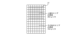
- the sensitivity adjustment unit 26 sets the sensitivity of pixels corresponding to the human detection area, which is the area in the thermal image where a person 2 is detected, higher than that of pixels corresponding to other areas. For example, the sensitivity of pixels in the human detection area is set to 30 digit/K, and the sensitivity of pixels outside the human detection area is set to 10 digit/K, and these are stored in the memory unit 14.
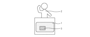
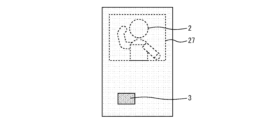
- Figure 4 shows a visible image.
- a heated object 3 is placed on the heating device 1, and a person 2 is standing in front of the heating device 1.
- Figure 5 is a flowchart for setting the human detection area and sensitivity.
- the human detection area setting unit 18 sets the human detection area (step S1).
- the sensitivity adjustment unit 26 changes the sensitivity of the pixels corresponding to the human detection area (step S2).
- Figure 6 is a diagram showing an image of the sensitivity setting of the infrared imaging device. For example, the sensitivity of the human detection area 27 is increased to 30 digit/K, and the sensitivity of the other areas is left at 10 digit/K.
- the thermal image generating unit 11 generates a thermal image using the brightness corrected by the sensitivity. As a result, the brightness of the person 2 photographed within the human detection area 27 is output relatively high, so the difference in brightness with the heat source outside the human detection area 27 is reduced, and the high-temperature subject and the person can be displayed simultaneously on the thermal image.
- Figures 7 and 8 are thermal images taken without adjusting the sensitivity of the human detection area.
- Figures 7 and 8 are thermal images taken without adjusting the sensitivity of the human detection area.
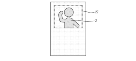
- Figure 9 is a thermal image taken with the sensitivity of the human detection area adjusted. The high-temperature heated object 3 and the person 2 can be displayed simultaneously on the thermal image.
- Figure 10 is a flowchart of human detection.
- the infrared imaging device 9 captures an image of a subject (step S11).
- the thermal image generation unit 11 generates and outputs a thermal image (step S12).
- the human detection unit 12 detects whether a person 2 is present in the thermal image (step S13). If a person 2 is not detected or is not present within the human detection area 27, the process returns to step S11. If a person 2 is present within the human detection area 27, an output is made indicating that a person has been detected (step S14). Note that the presence/absence of a person 2 may be determined only within the human detection area 27.
- the safety device 4 controls the output of the heating device 1 based on the detection result of the human detection unit 12 and the temperature information calculated by the temperature calculation unit 13. For example, the safety device 4 automatically controls the output of the heating device 1 when the person 2 is not in front of the heating device 1. Specifically, if the output of the heating device 1 is reduced or turned off when the person 2 is not in front of the heating device 1 and the heating device 1 has been on for a predetermined time, it is possible to prevent forgetting to turn it off and reduce energy consumption. Furthermore, when the person 2 is not in front of the heating device 1 and the temperature of the heating device 1 is too high, the safety device 4 reduces or turns off the output of the heating device 1. This makes it possible to prevent abnormal heat generation of the heated object 3, thereby improving the safety of the heating device 1.
- safety device 4 prevents automatic control of the output of heating device 1. This allows person 2 to manually control the heat of heating device 1. Furthermore, safety device 4 will not automatically reduce the heat even if person 2 intentionally increases the heat. This prevents person 2's operation from being hindered and convenience from being impaired.
- the sensitivity of pixels corresponding to the human detection area 27 is set higher than the sensitivity of pixels corresponding to other areas.
- the high-temperature subject and the person can be displayed simultaneously on the thermal image using an inexpensive MCU, making it possible to accurately detect person 2 on the thermal image.
- the temperature of the heat source can also be measured at the same time. Furthermore, by setting the human detection area 27 in advance, people who are not approaching the equipment, such as people walking in the aisle, will not be displayed on the thermal image, preventing erroneous detection.
- Embodiment 2 Fig. 11 is a diagram showing an infrared imaging device according to embodiment 2. The difference from embodiment 1 is that there is no sensitivity adjustment unit 26.
- Fig. 12 is a block diagram showing a heating system according to embodiment 2. The difference from embodiment 1 is that the safety device 4 has an offset setting unit 28.
- the human detection area setting unit 18 sets the upper limit temperature to be detected as a threshold value. For example, the threshold value is set to 38°C, which is slightly higher than the human body surface temperature.
- the other configurations are the same as those of embodiment 1.
- FIG. 13 is a flowchart showing the operation of the safety device according to the second embodiment.
- the infrared imaging device 9 captures an image (step S21).
- the temperature calculation unit 13 calculates the temperature of each pixel (step S22).
- the offset setting unit 28 determines whether there is a pixel outside the human detection area 27 that is hotter than the threshold (step S23). If there is, the offset setting unit 28 performs an offset process to reduce the brightness value output from the infrared imaging device 9 so that the temperature of the pixel becomes the same as the threshold, and outputs the result to the thermal image generation unit 11 (step S24).
- FIG. 14 is a diagram showing a thermal image before offset. For example, the temperature of the person 2 is 35°C, and the temperature of the heated object 3 is 100°C.
- FIG. 15 is a diagram showing a thermal image after offset. The temperature of the heated object 3 has been changed to the same temperature as the threshold 38°C.
- the thermal image generating unit 11 generates and outputs a thermal image in which the maximum and minimum brightness of the offset-processed data are assigned to a gradation according to the desired number of bits (step S25).
- the human detection unit 12 detects whether a person 2 is present in the thermal image (step S26). If a person 2 is not detected or is not present within the human detection area 27, the process returns to step S21. If a person 2 is present within the human detection area 27, an output is made indicating that a person has been detected (step S27).
- an offset process is performed to reduce the brightness value output from the infrared imaging device 9 so that the temperature of that pixel becomes the same as the threshold.
- This makes it possible to simultaneously display a high-temperature heat source and a person in a thermal image without providing the infrared imaging device 9 with a mechanism for adjusting pixel sensitivity.
- the offset is applied based on the threshold, it is possible to make a person appear the same on the thermal image regardless of the temperature of the heated object. This makes it possible to obtain high detection accuracy.
- erroneous detection can be suppressed.
- Embodiment 3 Similar to the second embodiment, there is no sensitivity adjustment unit 26, and the safety device 4 has an offset setting unit 28. The difference from the second embodiment is that the function of the offset setting unit 28 is different as described later, and the human detection area setting unit 18 does not set a threshold value.
- the other configurations are the same as those of the first and second embodiments.
- FIG. 16 is a flowchart showing the operation of the safety device according to the third embodiment.
- steps S21 and S22 are performed in the same manner as in the second embodiment.
- the offset setting unit 28 determines whether there is a pixel outside the human detection area 27 that is hotter than the maximum temperature of the human detection area 27 (step S31). If there is, the offset setting unit 28 performs an offset process to reduce the brightness value output from the infrared imaging device 9 so that the temperature of the pixel is the same as the maximum temperature of the human detection area 27, and outputs the result to the thermal image generating unit 11 (step S32).
- steps S25 to S27 are performed in the same manner as in the second embodiment.
- an offset process is performed to reduce the brightness value output from the infrared imaging device 9 so that the temperature of that pixel becomes the same as the maximum temperature.
- This makes it possible to simultaneously display a high-temperature heat source and a person in a thermal image without providing the infrared imaging device 9 with a mechanism for adjusting pixel sensitivity.
- this provides greater convenience than the second embodiment.
- it is possible to prevent the appearance of the person 2 in the thermal image from changing when the body surface temperature of the person 2 drops due to the outside air or rises due to heating by the heating device 1, thereby achieving high human detection accuracy.
- the maximum temperature may be determined for each frame, or at regular intervals. Also, if a heat source other than a person is captured in the human detection area 27, the offset may not function properly. Therefore, if a heat source of a predetermined temperature or higher is detected in the human detection area 27, an abnormality may be reported.
- Embodiment 4. 17 is a diagram showing a part of a safety device according to embodiment 4.
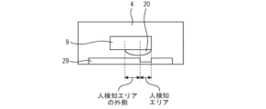
- a protective member 29 is disposed in front of the infrared transmitting lens 20 of the infrared imaging device 9 to prevent contamination of the infrared transmitting lens 20 and adjust the sensitivity.
- the protective member 29 is made of Si, germanium, high density polyethylene (HDPE), or the like that transmits infrared rays. Since the protective member 29 needs to be disposed at a distance that does not affect the imaging performance on the infrared imaging device 9, it is preferable to secure a distance of several centimeters or more between the infrared transmitting lens 20 and the protective member 29.
- the thickness of the protective member 29 in the area corresponding to the human detection area 27 is thinner than the thickness of the protective member 29 in the area corresponding to the outside of the human detection area 27.
- the protective member 29 in the area corresponding to the outside of the human detection area 27 is HDPE with a thickness of 0.5 mm
- the protective member 29 in the area corresponding to the outside of the human detection area 27 is HDPE with a thickness of 0.3 mm. This makes it possible to reduce the infrared transmittance in the area corresponding to the outside of the human detection area 27.
- the protective member 29 for adjusting the sensitivity also serves as the protective member for the module, preventing oil or water droplets from adhering to the infrared-transmitting lens 20 and preventing thermal image capture, improving product reliability.
- the luminance of the high-temperature heat source is set uniformly, so the luminance of the high-temperature subject may saturate and the temperature distribution inside the heat source may not be visible. Therefore, in the present embodiment, the sensitivity adjustment unit 26 switches the sensitivity of the entire pixels of the infrared imaging device 9 for each frame of images continuously captured by the infrared imaging device 9.
- the continuously captured images have a first frame and a second frame in which the sensitivity of the entire pixels is lower than that of the first frame.
- Figure 18 shows a first frame with high sensitivity.
- the luminance of person 2 is 200 digits.
- the luminance of both the outer periphery and center of the heated object 3 is saturated at 256 digits.
- Figure 19 shows a second frame with low sensitivity.
- the luminance of person 2 is 10 digits.
- the luminance of the outer periphery of the heated object 3 is 240 digits, and the luminance of the center is 220 digits.
- the thermal image generating unit 11 generates a thermal image by using a high-sensitivity first frame for the human detection area 27 and a low-sensitivity second frame for other areas. This makes it possible to display the high-temperature subject and the person 2 simultaneously on the thermal image using an inexpensive MCU, even if there is a high-temperature subject within the imaging range of the infrared imaging device 9, and therefore to accurately detect the person 2 on the thermal image.
- FIG. 20 shows a thermal image generated by the thermal image generation unit according to the fifth embodiment. It is possible to simultaneously display the high-temperature heated object 3 and the person 2 on the thermal image without losing information on the temperature distribution of the heated object 3. As a result, in addition to information on the presence/absence and status of the person, it is possible to obtain information on the temperature distribution of the heat source. This makes it possible to improve the controllability of the heating device 1. For example, when cooking on a stove, it is possible to control the heat according to the temperature distribution of ingredients inside a frying pan.
Landscapes
- Engineering & Computer Science (AREA)
- Physics & Mathematics (AREA)
- General Physics & Mathematics (AREA)
- Theoretical Computer Science (AREA)
- Chemical & Material Sciences (AREA)
- Combustion & Propulsion (AREA)
- Mechanical Engineering (AREA)
- General Engineering & Computer Science (AREA)
- Geophysics And Detection Of Objects (AREA)
Priority Applications (2)
| Application Number | Priority Date | Filing Date | Title |
|---|---|---|---|
| JP2023556753A JPWO2024247167A1 (https=) | 2023-05-31 | 2023-05-31 | |
| PCT/JP2023/020294 WO2024247167A1 (ja) | 2023-05-31 | 2023-05-31 | 加熱システム |
Applications Claiming Priority (1)
| Application Number | Priority Date | Filing Date | Title |
|---|---|---|---|
| PCT/JP2023/020294 WO2024247167A1 (ja) | 2023-05-31 | 2023-05-31 | 加熱システム |
Publications (1)
| Publication Number | Publication Date |
|---|---|
| WO2024247167A1 true WO2024247167A1 (ja) | 2024-12-05 |
Family
ID=93657038
Family Applications (1)
| Application Number | Title | Priority Date | Filing Date |
|---|---|---|---|
| PCT/JP2023/020294 Ceased WO2024247167A1 (ja) | 2023-05-31 | 2023-05-31 | 加熱システム |
Country Status (2)
| Country | Link |
|---|---|
| JP (1) | JPWO2024247167A1 (https=) |
| WO (1) | WO2024247167A1 (https=) |
Citations (4)
| Publication number | Priority date | Publication date | Assignee | Title |
|---|---|---|---|---|
| JP2000301340A (ja) * | 1999-04-21 | 2000-10-31 | Toshiba Corp | 自動溶接装置 |
| US20160338594A1 (en) * | 2011-04-04 | 2016-11-24 | James G. Spahn | Grayscale Thermographic Imaging |
| WO2017187811A1 (ja) * | 2016-04-27 | 2017-11-02 | ソニー株式会社 | 撮像制御装置及び撮像制御方法、並びに撮像装置 |
| JP2017224171A (ja) * | 2016-06-15 | 2017-12-21 | パナソニックIpマネジメント株式会社 | 調理支援方法および調理支援システム |
-
2023
- 2023-05-31 JP JP2023556753A patent/JPWO2024247167A1/ja active Pending
- 2023-05-31 WO PCT/JP2023/020294 patent/WO2024247167A1/ja not_active Ceased
Patent Citations (4)
| Publication number | Priority date | Publication date | Assignee | Title |
|---|---|---|---|---|
| JP2000301340A (ja) * | 1999-04-21 | 2000-10-31 | Toshiba Corp | 自動溶接装置 |
| US20160338594A1 (en) * | 2011-04-04 | 2016-11-24 | James G. Spahn | Grayscale Thermographic Imaging |
| WO2017187811A1 (ja) * | 2016-04-27 | 2017-11-02 | ソニー株式会社 | 撮像制御装置及び撮像制御方法、並びに撮像装置 |
| JP2017224171A (ja) * | 2016-06-15 | 2017-12-21 | パナソニックIpマネジメント株式会社 | 調理支援方法および調理支援システム |
Also Published As
| Publication number | Publication date |
|---|---|
| JPWO2024247167A1 (https=) | 2024-12-05 |
Similar Documents
| Publication | Publication Date | Title |
|---|---|---|
| JP5636116B2 (ja) | 赤外線アレイセンサーを利用した携帯用温度測定装置 | |
| CN104040310B (zh) | 用于检测对象在监视区域中的存在性的红外存在性检测器 | |
| US8970730B2 (en) | Imaging apparatus for controlling and displaying flicker amounts | |
| US8526780B2 (en) | Thermographic camera and method for the recording and/or modification and reproduction of thermal images of a scene and/or of an object | |
| KR20060064615A (ko) | 비냉각식 마이크로볼로미터 검출기를 이용한 복사 분석 | |
| US12215872B2 (en) | Auto detection system for cooking assistance and hair dryer with thermal detection | |
| US10999537B2 (en) | Compact camera | |
| JP2005249723A (ja) | 温度分布を含む画像の出力装置およびその制御方法 | |
| TWI803335B (zh) | 紅外線攝像裝置及固定型樣雜訊資料的生成方法 | |
| WO2024247167A1 (ja) | 加熱システム | |
| WO2015152388A1 (ja) | 照度検出ができる固体撮像装置およびこれを用いたカメラ、照明器具、表示装置 | |
| JPH10111172A (ja) | 赤外線撮像装置の感度補正方式 | |
| JP2008278036A (ja) | 赤外線カメラ | |
| JP5970965B2 (ja) | 撮像装置 | |
| GB2478708A (en) | Measuring the temperature of an object with an image sensor | |
| JP7399371B1 (ja) | 過剰加熱防止装置および加熱システム | |
| JP2022030434A (ja) | 赤外線画像処理装置、赤外線撮像システム、及び赤外線画像処理方法 | |
| KR20110021255A (ko) | 동영상 및 정지영상 처리 장치 및 그 방법 | |
| JPWO2024247167A5 (https=) | ||
| CN118464200A (zh) | 一种测定阴燃固体表面温度的双色热成像测温方法 | |
| CZ24140U1 (cs) | Zapojení pro detekci změny jasu ve videosignálu a pro detekci pohybu |
Legal Events
| Date | Code | Title | Description |
|---|---|---|---|
| WWE | Wipo information: entry into national phase |
Ref document number: 2023556753 Country of ref document: JP |
|
| 121 | Ep: the epo has been informed by wipo that ep was designated in this application |
Ref document number: 23939642 Country of ref document: EP Kind code of ref document: A1 |
|
| NENP | Non-entry into the national phase |
Ref country code: DE |