WO2024247151A1 - モータ制御装置、電動パワーステアリング装置、および車両 - Google Patents
モータ制御装置、電動パワーステアリング装置、および車両 Download PDFInfo
- Publication number
- WO2024247151A1 WO2024247151A1 PCT/JP2023/020216 JP2023020216W WO2024247151A1 WO 2024247151 A1 WO2024247151 A1 WO 2024247151A1 JP 2023020216 W JP2023020216 W JP 2023020216W WO 2024247151 A1 WO2024247151 A1 WO 2024247151A1
- Authority
- WO
- WIPO (PCT)
- Prior art keywords
- duty
- value
- side switching
- phase
- potential side
- Prior art date
- Legal status (The legal status is an assumption and is not a legal conclusion. Google has not performed a legal analysis and makes no representation as to the accuracy of the status listed.)
- Ceased
Links
Images






Classifications
-
- H—ELECTRICITY
- H02—GENERATION; CONVERSION OR DISTRIBUTION OF ELECTRIC POWER
- H02M—APPARATUS FOR CONVERSION BETWEEN AC AND AC, BETWEEN AC AND DC, OR BETWEEN DC AND DC, AND FOR USE WITH MAINS OR SIMILAR POWER SUPPLY SYSTEMS; CONVERSION OF DC OR AC INPUT POWER INTO SURGE OUTPUT POWER; CONTROL OR REGULATION THEREOF
- H02M1/00—Details of apparatus for conversion
- H02M1/0003—Details of control, feedback or regulation circuits
- H02M1/0009—Devices or circuits for detecting current in a converter
-
- H—ELECTRICITY
- H02—GENERATION; CONVERSION OR DISTRIBUTION OF ELECTRIC POWER
- H02M—APPARATUS FOR CONVERSION BETWEEN AC AND AC, BETWEEN AC AND DC, OR BETWEEN DC AND DC, AND FOR USE WITH MAINS OR SIMILAR POWER SUPPLY SYSTEMS; CONVERSION OF DC OR AC INPUT POWER INTO SURGE OUTPUT POWER; CONTROL OR REGULATION THEREOF
- H02M1/00—Details of apparatus for conversion
- H02M1/0003—Details of control, feedback or regulation circuits
- H02M1/0025—Arrangements for modifying reference values, feedback values or error values in the control loop of a converter
-
- H—ELECTRICITY
- H02—GENERATION; CONVERSION OR DISTRIBUTION OF ELECTRIC POWER
- H02M—APPARATUS FOR CONVERSION BETWEEN AC AND AC, BETWEEN AC AND DC, OR BETWEEN DC AND DC, AND FOR USE WITH MAINS OR SIMILAR POWER SUPPLY SYSTEMS; CONVERSION OF DC OR AC INPUT POWER INTO SURGE OUTPUT POWER; CONTROL OR REGULATION THEREOF
- H02M1/00—Details of apparatus for conversion
- H02M1/32—Means for protecting converters other than automatic disconnection
-
- H—ELECTRICITY
- H02—GENERATION; CONVERSION OR DISTRIBUTION OF ELECTRIC POWER
- H02M—APPARATUS FOR CONVERSION BETWEEN AC AND AC, BETWEEN AC AND DC, OR BETWEEN DC AND DC, AND FOR USE WITH MAINS OR SIMILAR POWER SUPPLY SYSTEMS; CONVERSION OF DC OR AC INPUT POWER INTO SURGE OUTPUT POWER; CONTROL OR REGULATION THEREOF
- H02M7/00—Conversion of AC power input into DC power output; Conversion of DC power input into AC power output
- H02M7/42—Conversion of DC power input into AC power output without possibility of reversal
- H02M7/44—Conversion of DC power input into AC power output without possibility of reversal by static converters
- H02M7/48—Conversion of DC power input into AC power output without possibility of reversal by static converters using discharge tubes with control electrode or semiconductor devices with control electrode
- H02M7/53—Conversion of DC power input into AC power output without possibility of reversal by static converters using discharge tubes with control electrode or semiconductor devices with control electrode using devices of a triode or transistor type requiring continuous application of a control signal
- H02M7/537—Conversion of DC power input into AC power output without possibility of reversal by static converters using discharge tubes with control electrode or semiconductor devices with control electrode using devices of a triode or transistor type requiring continuous application of a control signal using semiconductor devices only, e.g. single switched pulse inverters
- H02M7/5387—Conversion of DC power input into AC power output without possibility of reversal by static converters using discharge tubes with control electrode or semiconductor devices with control electrode using devices of a triode or transistor type requiring continuous application of a control signal using semiconductor devices only, e.g. single switched pulse inverters in a bridge configuration
- H02M7/53871—Conversion of DC power input into AC power output without possibility of reversal by static converters using discharge tubes with control electrode or semiconductor devices with control electrode using devices of a triode or transistor type requiring continuous application of a control signal using semiconductor devices only, e.g. single switched pulse inverters in a bridge configuration with automatic control of output voltage or current
-
- H—ELECTRICITY
- H02—GENERATION; CONVERSION OR DISTRIBUTION OF ELECTRIC POWER
- H02M—APPARATUS FOR CONVERSION BETWEEN AC AND AC, BETWEEN AC AND DC, OR BETWEEN DC AND DC, AND FOR USE WITH MAINS OR SIMILAR POWER SUPPLY SYSTEMS; CONVERSION OF DC OR AC INPUT POWER INTO SURGE OUTPUT POWER; CONTROL OR REGULATION THEREOF
- H02M7/00—Conversion of AC power input into DC power output; Conversion of DC power input into AC power output
- H02M7/42—Conversion of DC power input into AC power output without possibility of reversal
- H02M7/44—Conversion of DC power input into AC power output without possibility of reversal by static converters
- H02M7/48—Conversion of DC power input into AC power output without possibility of reversal by static converters using discharge tubes with control electrode or semiconductor devices with control electrode
- H02M7/53—Conversion of DC power input into AC power output without possibility of reversal by static converters using discharge tubes with control electrode or semiconductor devices with control electrode using devices of a triode or transistor type requiring continuous application of a control signal
- H02M7/537—Conversion of DC power input into AC power output without possibility of reversal by static converters using discharge tubes with control electrode or semiconductor devices with control electrode using devices of a triode or transistor type requiring continuous application of a control signal using semiconductor devices only, e.g. single switched pulse inverters
- H02M7/539—Conversion of DC power input into AC power output without possibility of reversal by static converters using discharge tubes with control electrode or semiconductor devices with control electrode using devices of a triode or transistor type requiring continuous application of a control signal using semiconductor devices only, e.g. single switched pulse inverters with automatic control of output wave form or frequency
- H02M7/5395—Conversion of DC power input into AC power output without possibility of reversal by static converters using discharge tubes with control electrode or semiconductor devices with control electrode using devices of a triode or transistor type requiring continuous application of a control signal using semiconductor devices only, e.g. single switched pulse inverters with automatic control of output wave form or frequency by pulse-width modulation
Definitions
- This disclosure relates to a motor control device, an electric power steering device, and a vehicle.
- a motor control device that controls a motor includes an inverter circuit having a high-side switching element and a low-side switching element, and a power control unit that controls the inverter circuit.
- a current sensor is connected to the low-side switching element, and the current value detected by the current sensor is typically used to control the inverter circuit.
- Patent Documents 1 and 2 disclose a configuration in which the motor control device is provided with an abnormality detection unit that detects abnormalities based on the current value detected by the current sensor when no current flows through the current sensor (hereinafter referred to as the offset current value).
- the present disclosure aims to provide a motor control device, an electric power steering device, and a vehicle that can prevent a decrease in motor output during normal operation and can detect abnormalities based on the offset current value with high accuracy and without delay even when the output of the inverter circuit is high.
- One aspect of the motor control device disclosed herein is an inverter circuit that supplies power to a motor having windings of multiple phases, the inverter circuit having a plurality of high-potential side switching elements and a plurality of low-potential side switching elements provided corresponding to each of the multiple phases, and a plurality of current sensors respectively connected to the multiple low-potential side switching elements, a power control unit that controls the multiple high-potential side switching elements and the multiple low-potential side switching elements based on a duty value, and a first threshold value that detects an abnormality by comparing, for each of the multiple phases, an offset current value detected using the current sensor when the low-potential side switching element is in a non-conducting state.
- the abnormality detection unit causes the power control unit to perform a duty limiting process, which is a process of generating a limiting duty value for the limiting phase including at least the phase in which the abnormality is detected among the multiple phases, limiting the duty value of the limiting phase to a predetermined lower limit value or more so that the time during which the low-potential side switching element is in a non-conducting state is equal to or longer than the time required to detect the offset current value, and controlling the high-potential side switching element and the low-potential side switching element based on the limiting duty value.
- a duty limiting process which is a process of generating a limiting duty value for the limiting phase including at least the phase in which the abnormality is detected among the multiple phases, limiting the duty value of the limiting phase to a predetermined lower limit value or more so that the time during which the low-potential side switching element is in a non-conducting state is equal to or longer than the time required to detect the offset current value, and controlling the high-potential
- One embodiment of the electric power steering device includes the motor control device, the motor that assists steering of the steering wheel, and a torque sensor that detects the steering torque caused by steering of the steering wheel, and the motor control device controls the drive of the motor according to the steering torque detected by the torque sensor.
- One embodiment of the vehicle disclosed herein includes the electric power steering device and a notification unit that notifies the occurrence of a malfunction when the abnormality detection unit determines that a malfunction has occurred.
- FIG. 1 is an overall configuration diagram of a motor control device according to a first embodiment
- FIG. 2 is a block diagram of a power control unit according to the first embodiment.
- 4 is a diagram for explaining the principle of generation of a switching signal in a PWM generating unit according to the first embodiment
- FIG. 5 is a diagram showing an example of a duty value input to a power control unit according to the first embodiment
- FIG. 5 is a diagram showing an example of a duty value input to a PWM generating unit according to the first embodiment
- FIG. 5 is a flowchart showing a flow of processing performed by an abnormality detection unit according to the first embodiment
- 13 is a flowchart showing a flow of processing performed by an abnormality detection unit according to a modification of the first embodiment.
- FIG. 1 is an overall configuration diagram of a motor control device according to a first embodiment
- FIG. 2 is a block diagram of a power control unit according to the first embodiment.
- 4 is a diagram for explaining the principle of generation of a
- FIG. 11 is a schematic configuration diagram of an electric power steering device according to a second embodiment.
- FIG. 11 is a diagram showing an example of a duty value input to a PWM generating unit according to the third embodiment
- FIG. 11 is a diagram showing an example of a duty value input to a PWM generating unit according to the third embodiment
- FIG. 13 is a diagram showing an example of a duty value input to a PWM generating unit according to the fourth embodiment
- Embodiment 1. 1 is an overall configuration diagram of a motor control device 100 according to a first embodiment.
- the motor control device 100 includes an inverter circuit 1, an abnormality detection unit 4, a power control unit 5, a current value acquisition unit 6, and a duty value generation unit 7.
- the motor control device 100 controls a motor 3 based on a control command input from outside the motor control device 100.
- a motor that is driven to rotate by a polyphase AC can be used as the motor 3.
- the motor 3 is a three-phase brushless motor having a three-phase winding composed of a U-phase winding, a V-phase winding, and a W-phase winding.
- the inverter circuit 1 is supplied with a DC voltage from the DC power supply unit 2.
- the inverter circuit 1 applies an AC voltage to the three-phase windings of the motor 3 based on the DC voltage output from the DC power supply unit 2.
- the inverter circuit 1 includes high-potential side switching elements 11u, 11v, and 11w, low-potential side switching elements 12u, 12v, and 12w, and current sensors 13u, 13v, and 13w.
- the inverter circuit 1 also includes a power supply line L1 connected to the positive electrode of the DC power supply unit 2, and a ground line L2 connected to the negative electrode of the DC power supply unit 2.
- the high-potential side switching element 11u, the low-potential side switching element 12u, and the current sensor 13u are provided to correspond to the U phase of the motor 3.
- the high-potential side switching element 11v, the low-potential side switching element 12v, and the current sensor 13v are provided to correspond to the V phase of the motor 3.
- the high-potential side switching element 11w, the low-potential side switching element 12w, and the current sensor 13w are provided to correspond to the W phase of the motor 3.
- the high-potential side switching elements 11u, 11v, and 11w may be collectively referred to simply as “high-potential side switching element 11.”
- the low-potential side switching elements 12u, 12v, and 12w may be collectively referred to simply as “low-potential side switching element 12.”
- the current sensors 13u, 13v, and 13w may be collectively referred to simply as "current sensor 13.”
- the high-potential side switching elements 11u, 11v, and 11w are connected to the power supply line L1.
- the low-potential side switching elements 12u, 12v, and 12w are connected to the high-potential side switching elements 11u, 11v, and 11w, respectively, and are also connected to the ground line L2 via the current sensors 13u, 13v, and 13w, respectively.
- the connection point between the high-potential side switching element 11u and the low-potential side switching element 12u is connected to the U-phase winding of the motor 3.
- the connection point between the high-potential side switching element 11v and the low-potential side switching element 12v is connected to the V-phase winding of the motor 3.
- the connection point between the high-potential side switching element 11w and the low-potential side switching element 12w is connected to the W-phase winding of the motor 3.
- the high-potential side switching elements 11u, 11v, 11w are respectively input with switching signals Gup, Gvp, Gwp output from the power control unit 5.
- the low-potential side switching elements 12u, 12v, 12w are respectively input with switching signals Gun, Gvn, Gwn output from the power control unit 5.
- the inverter circuit 1 performs chopper control of the high-potential side switching elements 11u, 11v, 11w and the low-potential side switching elements 12u, 12v, 12w based on the switching signals Gup, Gvp, Gwp, Gun, Gvn, Gwn.
- the high-potential side switching elements 11u, 11v, 11w and the low-potential side switching elements 12u, 12v, 12w are turned on (conductive) or off (non-conductive) by the switching signals Gup, Gvp, Gwp, Gun, Gvn, Gwn.
- the high potential side switching element 11u is in the on state
- the high potential side switching element 11u is in the off state.
- the other switching elements 11v, 11w, 12u, 12v, and 12w are turned on (conductive) or off (non-conductive) by the switching signals Gup, Gvp, Gwp, Gun, Gvn, Gwn.
- the inverter circuit 1 passes current through the three-phase windings of the motor 3 by switching the on and off states of the switching elements 11u, 11v, 11w, 12u, 12v, and 12w using the switching signals Gup, Gvp, Gwp, Gun, Gvn, and Gwn. This generates motor torque.
- the high-side switching elements 11u, 11v, 11w and the low-side switching elements 12u, 12v, 12w are, for example, FETs (Field Effect Transistors).
- the switching elements 11u, 11v, 11w, 12u, 12v, 12w may be any device that can switch between an on state and an off state by a switching signal.
- the switching elements 11u, 11v, 11w, 12u, 12v, 12w may be thyristors or bipolar transistors.
- Current sensors 13u, 13v, 13w are disposed between low-potential side switching elements 12u, 12v, 12w and ground line L2.
- Current sensors 13u, 13v, 13w are connected in series to low-potential side switching elements 12u, 12v, 12w, respectively.
- Current sensors 13u, 13v, 13w detect the current values flowing through low-potential side switching elements 12u, 12v, 12w, respectively.
- Current sensors 13u, 13v, 13w are, for example, shunt resistors. It is sufficient for current sensors 13u, 13v, 13w to detect the current values flowing through low-potential side switching elements 12u, 12v, 12w.
- current sensors 13u, 13v, 13w may be CTs (Current Transformers) or Hall elements.
- the current values detected by the current sensors 13u, 13v, and 13w are input to the current value acquisition unit 6.
- the current value acquisition unit 6 has a sample-and-hold circuit.
- the current value acquisition unit 6 acquires offset current values Iu, Iv, and Iw by performing a sample-and-hold process that holds the current values detected by the current sensors 13u, 13v, and 13w at a predetermined sample timing, and outputs the acquired offset current values Iu, Iv, and Iw to the abnormality detection unit 4, etc.
- the offset current value Iu is the U-phase current value detected using the current sensor 13u when no current flows through the low-potential side switching element 12u (current sensor 13u).
- the offset current value Iv is the V-phase current value detected by the current sensor 13v when no current flows through the low-potential side switching element 12v (current sensor 13v).
- the offset current value Iw is the W-phase current value detected by the current sensor 13w when no current flows through the low-potential side switching element 12w (current sensor 13w).
- the sample timing occurs at every predetermined current detection period Ti. The sample timing is set to the timing when the low-potential side switching elements 12u, 12v, and 12w are in the off state.
- the offset current values Iu, Iv, and Iw are used to calibrate the current sensor 13, for example, so that the value of the current sensor 13 when no current flows becomes 0 (A).
- the offset current values Iu, Iv, and Iw are also used to detect an abnormality in the abnormality detection unit 4.
- the abnormality detection unit 4 detects an abnormality in the power supply path that supplies power to the motor 3 based on the offset current values Iu, Iv, Iw detected using the current sensors 13u, 13v, 13w.
- the abnormality detection unit 4 also determines a failure based on the number of times an abnormality is detected. Examples of causes of the above failure include short-circuit failures of the low-potential side switching elements 12u, 12v, 12w, failures of the current sensors 13u, 13v, 13w, and failures of the current value acquisition unit 6.
- any one of the three phases will be referred to as the "x-phase”, and the offset current value of the x-phase will be referred to as the "offset current value Ix”.
- the abnormality detection unit 4 compares the offset current value Ix input from the current value acquisition unit 6 with a predetermined abnormality detection threshold Ith (first threshold). If the offset current value Ix is equal to or less than the abnormality detection threshold Ith, the abnormality detection unit 4 determines that there is no abnormality in the x phase. If the offset current value Ix is greater than the abnormality detection threshold Ith, the abnormality detection unit 4 determines that there is an abnormality in the x phase (i.e., detects an abnormality in the x phase).
- the offset current value Ix will be "0", so it is ideal to set the abnormality detection threshold Ith to "0".
- the abnormality detection threshold Ith is set to a value slightly greater than "0".
- the abnormality detection unit 4 outputs a duty limiting process flag according to the above detection result to the power control unit 5. Specifically, the abnormality detection unit 4 outputs the duty limiting process flag of the phase in which the abnormality was detected as "true" to the power control unit 5.
- the abnormality detection unit 4 does not determine a fault for a phase in which an abnormality is detected by detecting an abnormality only once, but determines a fault by detecting an abnormality multiple times. Details of fault determination will be described later.
- the abnormality detection unit 4 outputs a fault determination flag to an external control device, etc. This causes processes such as notifying the user of the motor 3 of the occurrence of a fault and stopping the motor 3 in accordance with a predetermined process to be performed.
- a control command is input to the duty value generation unit 7 from the outside.
- the duty value generation unit 7 generates a duty value based on the control command.
- the duty value generation unit 7 outputs the duty value to the power control unit 5.
- the duty values include a U-phase duty value, a V-phase duty value, and a W-phase duty value.
- the U-phase duty value corresponds to the voltage to be applied to the U-phase winding of the motor 3.
- the U-phase duty value indicates the proportion of time that current is applied to the high-potential side switching element 11u of the U-phase for one period of the signal (the carrier period Tc of the carrier triangular wave C described below), and ranges between 0 and 1 (0% to 100%).
- the power control unit 5 receives a duty value from the duty value generation unit 7.
- the power control unit 5 receives a duty limiting processing flag from the abnormality detection unit 4.
- the power control unit 5 drives the inverter circuit 1 based on the duty value and the duty limiting processing flag.
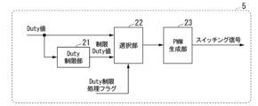
- FIG. 2 is a block diagram of the power control unit 5. As shown in FIG. 2, the power control unit 5 has a duty limiting unit 21, a selecting unit 22, and a PWM generating unit 23.
- the duty limiting unit 21 receives a duty value from the duty value generating unit 7.
- the duty limiting unit 21 generates a limited duty value by limiting the duty value received from the duty value generating unit 7 to a predetermined limit threshold Duty_th (lower limit value) or greater.
- the duty limiting unit 21 generates a limited duty value by performing clipping processing to make a duty value smaller than the limit threshold Duty_th match the limit threshold Duty_th.
- the duty limiting unit 21 outputs the limited duty value to the selecting unit 22.
- the selection unit 22 receives the duty value from the duty value generation unit 7.
- the selection unit 22 receives the restricted duty value from the duty restriction unit 21.
- the selection unit 22 receives the duty restriction processing flag from the abnormality detection unit 4.
- the selection unit 22 selects the duty value to be output to the PWM generation unit 23 based on the duty restriction processing flag. Specifically, for restricted phases including at least phases for which the duty restriction processing flag indicates "true", the selection unit 22 outputs the restricted duty value generated by the duty restriction unit 21 to the PWM generation unit 23. For phases other than the restricted phases, the selection unit 22 outputs the duty value output from the duty value generation unit 7 (i.e., the duty value that is not restricted to or above the restriction threshold Duty_th) to the PWM generation unit 23.
- the phase to be limited is the phase for which the duty limiting process flag indicates "true”. That is, for example, if the duty limiting process flag for the U phase indicates “true” and the duty limiting process flags for the V phase and W phase indicate "false", the selection unit 22 outputs the limited duty value for the U phase generated by the duty limiting unit 21 and the duty value for the V phase and the duty value for the W phase output from the duty value generating unit 7 to the PWM generating unit 23.
- the limited duty value or the duty value output from the selection unit 22 to the PWM generating unit 23 may be collectively referred to simply as "duty value".
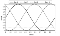
- FIG. 4 is a diagram showing an example of the duty values input from the duty value generation unit 7 to the power control unit 5.
- the horizontal axis of FIG. 4 indicates time, and the vertical axis indicates the duty value.
- the duty value of the U phase is shown as DutyU
- the duty value of the V phase is shown as DutyV
- the duty value of the W phase is shown as DutyW.
- the duty value of each phase changes in a sinusoidal manner.
- FIG. 5 is a diagram showing an example of the duty value input to the PWM generating unit 23 when the phase to be limited is the U phase.
- the horizontal axis of FIG. 5 indicates time, and the vertical axis indicates the duty value.
- the limit duty value of the U phase is shown as DutyU_Limit.
- the PWM generation unit 23 Based on the duty value input from the selection unit 22, the PWM generation unit 23 generates switching signals Gup, Gvp, Gwp, Gun, Gvn, and Gwn, which are control signals by PWM (Pulse Width Modulation) control, and outputs them to the inverter circuit 1.
- PWM Pulse Width Modulation
- the PWM generation unit 23 controls the high-potential side switching elements 11u, 11v, and 11w and the low-potential side switching elements 12u, 12v, and 12w based on the duty value input from the selection unit 22.
- the PWM generation unit 23 controls the high-potential side switching elements 11u, 11v, and 11w and the low-potential side switching elements 12u, 12v, and 12w based on the limited duty value generated by the duty limiting unit 21.
- the PWM generating unit 23 controls the high-potential side switching elements 11u, 11v, 11w and the low-potential side switching elements 12u, 12v, 12w based on the duty value output from the duty value generating unit 7.
- the power control unit 5 when the power control unit 5 receives a duty limiting process flag indicating "true” from the abnormality detection unit 4, the power control unit 5 generates a limiting duty value that limits the duty value output from the duty value generation unit 7 to the limiting threshold Duty_th or more for the phases to be limited, including at least the phase to which the duty limiting process flag indicating "true” has been received, and performs a duty limiting process that controls the high-potential side switching elements 11u, 11v, 11w and the low-potential side switching elements 12u, 12v, 12w based on the limiting duty value.
- the power control unit 5 may perform the duty limiting process by changing the process or threshold in the duty limiting unit 21 according to the duty limiting process flag without using the selection unit 22.
- the duty limiting unit 21 For example, for the phase to be limited, the duty limiting unit 21 generates a limited duty value that limits the duty value to the limit threshold Duty_th or more, and outputs it to the PWM generating unit 23.
- the duty limiting unit 21 does not process the duty value output from the duty value generating unit 7, and outputs the duty value output from the duty value generating unit 7 to the PWM generating unit 23 as it is.
- the PWM generating unit 23 controls the high-potential side switching elements 11u, 11v, 11w and the low-potential side switching elements 12u, 12v, 12w based on the duty value input from the duty limiting unit 21.
- FIG. 3 shows the time series changes of the U-phase duty value, the carrier triangular wave C with carrier period Tc (carrier frequency fc), and the U-phase switching signals Gup and Gun.
- the horizontal axis of FIG. 3 indicates time, and the vertical axis indicates signal level.
- the carrier frequency fc is, for example, 20 kHz.
- the U-phase duty value ranges from 0 to 1 (0% to 100%).
- the carrier triangular wave C also ranges from 0 to 1 (0% to 100%).
- the PWM generation unit 23 generates the U-phase switching signals Gup and Gun by comparing the U-phase duty value with the carrier triangular wave C.
- the PWM generating unit 23 sets the high potential side switching signal Gup to "1" as an ON command and sets the low potential side switching signal Gun to "0" as an OFF command. That is, when the duty value of the U phase is greater than the carrier triangular wave C, the high potential side switching element 11u of the U phase is turned on and the low potential side switching element 12u of the U phase is turned off. When the duty value of the U phase is smaller than the carrier triangular wave C, the PWM generating unit 23 sets the high potential side switching signal Gup to "0" as an OFF command and sets the low potential side switching signal Gun to "1" as an ON command.
- the duty value includes a duty value of the U phase, a duty value of the V phase, and a duty value of the W phase.
- the time during which the low-potential side switching element 12 of the phase to which this switching signal is input is in the ON state becomes longer (i.e., the time during which the low-potential side switching element 12 is in the OFF state becomes shorter).
- the time required to detect the offset current value using the current sensor 13 is called the current detection time.
- the abnormality detection unit 4 determines a failure by detecting an abnormality multiple times. In order to make such a fault determination, it is necessary to constantly detect the offset current value of the phase in which an abnormality is detected during the fault determination period. In the example of Fig. 4, for example, in the period from 0.15 seconds to about 0.3 seconds, the duty values of the three phases are equal to or greater than the limit threshold Duty_th.
- a limiting duty value is generated for the phase to be limited, limiting the duty value to equal to or greater than the limiting threshold Duty_th, and a duty limiting process is performed to control the high-potential side switching elements 11u, 11v, 11w and the low-potential side switching elements 12u, 12v, 12w based on the limiting duty value.
- the limiting threshold Duty_th is set to a value that ensures that the time during which the low-potential side switching element 12 is in the off state is equal to or greater than the current detection time (e.g., 5 ⁇ s).
- the limiting threshold Duty_th is, for example, 0.1 (10%).
- the time during which the low-potential side switching element 12 is in the off state for the phase to be limited can be ensured to be equal to or longer than the current detection time, so that the offset current value can be reliably acquired using the current sensor 13.
- the duty limiting process it is possible to reliably detect an abnormality based on the offset current value for the phase to be limited.
- the duty value is equal to or greater than the limiting threshold Duty_th
- the low-potential side switching elements 12u, 12v, and 12w of all phases are in the off state near the time when the carrier triangular wave C becomes 0. Therefore, the sampling timing in the current value acquiring unit 6 is set to the above time.
- FIG. 6 is a flowchart showing the flow of processing performed by the abnormality detection unit 4.
- the abnormality detection processing by the abnormality detection unit 4 is performed, for example, at every current detection period Ti.
- the current detection period Ti is an integer multiple of the carrier period Tc of the carrier triangular wave C.
- the abnormality detection processing by the abnormality detection unit 4 may be performed at every period that is an integer multiple of the current detection period Ti.
- the abnormality detection processing by the abnormality detection unit 4 is performed in parallel for each of the U phase, V phase, and W phase. Below, an example will be described in which the abnormality detection processing is performed in the "x phase", which is any one of the three phases.
- step S101 the abnormality detection unit 4 acquires Duty_x, which is the duty value of the x phase, and determines whether or not Duty_x is smaller than the limit threshold Duty_th. If Duty_x is smaller than the limit threshold Duty_th (step S101: YES), the offset current value Ix of the x phase cannot be detected, and the determination in the subsequent step S102 cannot be made, so this flow chart is terminated.
- step S101 If Duty_x is equal to or greater than the limit threshold Duty_th (step S101: NO), the process proceeds to step S102.
- step S102 the abnormality detection unit 4 calculates the absolute value
- step S102 If the absolute value
- step S102 If the absolute value
- the abnormality detection unit 4 increments a free-running counter (FRC) indicating the number of times an abnormality has been detected by 1.
- FRC free-running counter
- step S104 the abnormality detection unit 4 sets the duty limiting process flag for the x-phase to "true” and outputs it to the power control unit 5. This causes the power control unit 5 to execute the duty limiting process.
- step S104 the process proceeds to step S201. Note that if the power control unit 5 has already executed the duty limiting process, the determination result in step S101 is always "YES", and the process always proceeds to step S102 after step S101.
- step S201 it is determined whether it is time to execute the failure determination routine. Specifically, in step S201, the abnormality detection unit 4 determines whether the current cycle is a preset failure determination cycle Te.
- the failure determination cycle Te is an integer multiple (e.g., several to several tens of times) of the current detection cycle Ti. If the current cycle is not the failure determination cycle Te (step S201: NO), this flowchart ends.
- step S201 If the current cycle is the failure determination cycle Te (step S201: YES), the process proceeds to step S202.
- step S202 the abnormality detection unit 4 determines whether the free-run counter (FRC) is the same as the free-run counter (FRCpast) at the time the previous failure determination routine was executed.
- step S103 has been executed one or more times since the previous fault determination routine was executed. That is, since the previous fault determination routine was executed, it has been determined in step S102 that the absolute value
- step S204 the abnormality detection unit 4 determines whether the abnormality counter is equal to or greater than the fault determination threshold Nth. If the abnormality counter is equal to or greater than the fault determination threshold Nth (step S204: YES), in step S205, the abnormality detection unit 4 determines that a fault has occurred and outputs a fault determination flag to an external control device or the like.
- step S204 If the abnormality counter is less than the fault determination threshold Nth (step S204: NO), processing proceeds to step S208.
- step S103 has not been executed since the previous execution of the fault determination routine. That is, since the previous execution of the fault determination routine, the state in which the absolute value
- the abnormality detection unit 4 sets the duty limiting process flag for the x-phase to "false” and outputs it to the power control unit 5. As a result, the power control unit 5 cancels (ends) the duty limiting process.
- step S207 the abnormality detection unit 4 resets the abnormality counter. Then, the process proceeds to step S208.
- step S208 the abnormality detection unit 4 assigns the free-running counter (FRC) to the variable FRCpast and ends this flowchart.
- FRC free-running counter
- the abnormality detection unit 4 detects abnormalities by comparing the offset current values Iu, Iv, Iw detected using the current sensors 13u, 13v, 13w when the low-potential side switching elements 12u, 12v, 12w are in the off state with an abnormality detection threshold Ith for each of the multiple phases, and determines whether a failure has occurred based on the number of times the abnormality has been detected.
- the abnormality detection unit 4 causes the power control unit 5 to perform a duty limiting process, which is a process of generating a limiting duty value that limits the duty value of the limited phase, including at least the phase in which the abnormality was detected, to a predetermined limiting threshold Duty_th or more so that the time during which the low-potential side switching elements 12u, 12v, and 12w are in the off state is equal to or longer than the time required to detect the offset current values Iu, Iv, and Iw, and controlling the high-potential side switching elements 11u, 11v, and 11w and the low-potential side switching elements 12u, 12v, and 12w based on the limiting duty value.
- a duty limiting process is a process of generating a limiting duty value that limits the duty value of the limited phase, including at least the phase in which the abnormality was detected, to a predetermined limiting threshold Duty_th or more so that the time during which the low-potential side switching elements 12u, 12v, and 12w are in the off
- the abnormality detection unit 4 When an abnormality is detected by comparing the offset current values Iu, Iv, and Iw with the abnormality detection threshold Ith, the abnormality detection unit 4 causes the power control unit 5 to perform duty limiting processing for at least the phase to be limited including the phase in which the abnormality was detected.
- the time during which the low potential side switching elements 12u, 12v, and 12w are in the off state is longer than the time required to detect the offset current values Iu, Iv, and Iw, so that even if the output of the inverter circuit 1 is high, the offset current values Iu, Iv, and Iw can be reliably detected in the next and subsequent comparisons.
- the power control unit 5 controls the multiple high potential side switching elements 11u, 11v, 11w and the multiple low potential side switching elements 12u, 12v, 12w based on the Duty value without limiting the Duty value to or above the limit threshold Duty_th. Therefore, it is possible to prevent a decrease in the output of the motor 3 during normal operation. As a result, a decrease in the output of the motor 3 during normal operation can be prevented, and even when the output of the inverter circuit 1 is high, abnormalities can be detected accurately and without delay based on the offset current values Iu, Iv, and Iw.
- the anomaly detection unit 4 determines whether a fault has occurred based on the number of times an anomaly has been detected, which can reduce erroneous determinations of faults caused by noise, etc.
- the abnormality detection unit 4 performs a determination of an abnormality for each abnormality determination period Te, and releases the duty limiting process if no abnormality is detected consecutively in the determination of an abnormality for each abnormality determination period Te. This makes it possible to prevent the duty limiting process from being released at an inappropriate time even if it is erroneously determined that there is no abnormality due to noise or the like, despite the occurrence of a failure.
- the power control unit 5 generates a limited duty value by matching the duty value of the phase to be limited, which is smaller than the abnormality detection threshold Ith, to the abnormality detection threshold Ith. This makes it possible to suppress a decrease in the output of the motor 3 due to the duty limiting process.
- the phase to be restricted is a phase in which an abnormality is detected by the abnormality detection unit 4 . This makes it possible to more effectively suppress the decrease in output of the motor 3.
- a modified example of embodiment 1. 7 is a flowchart showing a flow of processing performed by the abnormality detection unit 4 according to a modification of embodiment 1.
- the current detection period Ti and the failure determination period Te are the same, and steps S103, S201, and S202 are omitted.
- step S102 if the absolute value
- the abnormality detection unit 4 sets the duty limiting process flag for the x-phase to "false” and outputs it to the power control unit 5. This causes the power control unit 5 to cancel (end) the duty limiting process.
- step S207 the abnormality detection unit 4 resets the abnormality counter, and ends this flowchart.
- step S102 if the absolute value
- step S104 the abnormality detection unit 4 sets the duty limiting process flag for the x phase to "true” and outputs it to the power control unit 5. This causes the power control unit 5 to execute the duty limiting process.
- step S104 proceeds to step S203.
- step S203 the abnormality detection unit 4 increments the abnormality counter by 1. Then, the process proceeds to step S204.
- step S204 the abnormality detection unit 4 determines whether the abnormality counter is equal to or greater than the fault determination threshold Nth. If the abnormality counter is smaller than the fault determination threshold Nth (step S204: NO), this flow chart ends. If the abnormality counter is equal to or greater than the fault determination threshold Nth (step S204: YES), in step S205, the abnormality detection unit 4 determines that a fault has occurred and outputs a fault determination flag to an external control device or the like, and this flow chart ends.
- Embodiment 2 The motor control device 100 according to the first embodiment can be applied to an electric power steering device for a vehicle.
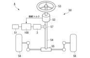
- An electric power steering device 50 and a vehicle A according to a second embodiment will be described below with reference to Fig. 8. Note that components having the same functions and actions as those in the first embodiment are given the same reference numerals and descriptions thereof will be omitted.
- vehicle A includes an electric power steering device 50 and a notification unit 51.
- the electric power steering device 50 includes a motor 3, a motor control device 100, a torque sensor 52, a steering wheel 53, a steering shaft 54, a rack and pinion gear 55, wheels 56, and a reduction gear 57.
- the steering wheel 53 is steered by the driver.
- the steering shaft 54 is connected to the steering wheel 53 and the rack and pinion gear 55.
- the steering torque applied by the driver to the steering wheel 53 is transmitted to the rack and pinion gear 55 via the steering shaft 54.
- the rack included in the rack and pinion gear 55 is connected to the wheels 56 via a tie rod and a knuckle arm.
- the motor 3 functions as a driving force source that assists the steering of the steering wheel 53. Specifically, the motor 3 is connected to the steering shaft 54 via a reduction gear 57. The motor torque generated by the motor 3 is transmitted to the steering shaft 54 via the reduction gear 57, reducing the steering force applied by the driver when steering.
- the torque sensor 52 is attached to the steering shaft 54.
- the torque sensor 52 detects the steering torque applied to the steering shaft 54 when the driver turns the steering wheel 53.
- the torque sensor 52 outputs the detected steering torque to the motor control device 100.
- the duty value generation unit 7 receives the steering torque detected by the torque sensor 52 as an input and generates a duty value.
- the duty value generation unit 7 outputs the generated duty value to the power control unit 5.
- the power control unit 5 drives the inverter circuit 1 based on the duty value. As a result, a current is supplied from the inverter circuit 1 to the motor 3, and a motor torque is generated.
- the notification unit 51 is connected to the motor control device 100.
- the abnormality detection unit 4 determines that a fault has occurred, it outputs a fault determination flag to the notification unit 51.
- the notification unit 51 notifies the driver of the occurrence of the fault.
- the notification unit 51 may include a display unit (not shown) and display the occurrence of the fault on the display unit.
- the electric power steering device 50 includes the motor control device 100, the motor 3 that assists the steering of the steering wheel 53, and the torque sensor 52 that detects the steering torque caused by the steering of the steering wheel 53.
- the motor control device 100 controls the driving of the motor 3 according to the steering torque detected by the torque sensor 52.
- the motor control device 100 is provided in the electric power steering device 50, the abnormality detection unit 4 can detect the abnormality with high accuracy and without delay, and the failure can be determined accurately in a short time. Therefore, when a failure occurs, the control can be quickly shifted to a control corresponding to the abnormal state, and the discomfort felt by the driver can be reduced. In addition, the deterioration of the steering feeling during the failure determination can be suppressed.
- the vehicle A according to this embodiment also includes an electric power steering device 50 and a notification unit 51 that notifies the occurrence of a malfunction when the abnormality detection unit 4 determines that a malfunction has occurred. This makes it possible to notify the driver of a malfunction when one occurs.
- Embodiment 3 Next, a description will be given of a motor control device according to embodiment 3.
- the basic configuration of the motor control device according to this embodiment is similar to that of the motor control device according to embodiment 1, so the following description will focus on the differences.
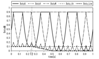
- FIG. 9 and 10 are diagrams showing an example of the duty value input to the PWM generating unit 23 in the third embodiment.
- the horizontal axis of FIG. 9 and FIG. 10 indicates time, and the vertical axis indicates the duty value.
- the duty limiting unit 21 generates the limited duty value by performing an amplitude reduction process to reduce the amplitude of the duty value. Specifically, the duty limiting unit 21 generates the limited duty value by multiplying the amplitude of the duty value by a coefficient Duty_Lim such that the minimum value of the limited duty value is equal to or greater than the limited threshold Duty_th.
- the coefficient Duty_Lim is smaller than 1, for example, 0.9.
- the limited duty value changes in a sinusoidal manner, similar to the duty value.
- the oscillation center of the limited duty value is maintained at 0.5.
- the power control unit 5 does not change the duty value instantly, but rather gradually reduces the amplitude of the duty value by gradually decreasing the coefficient Duty_Lim from 1 at the start of the duty limiting process, and gradually increases the amplitude of the duty value by gradually increasing the coefficient Duty_Lim to 1 at the end of the duty limiting process.
- the duty limiting process is not performed from time 0 seconds to time T1 (near 0.57 seconds), and the duty limiting process is started at time T1. Also, from time T1, the coefficient Duty_Lim is gradually decreased to gradually decrease the amplitude of the duty value. Also, in the example of Fig.
- the duty limiting process is performed from time 0 seconds to time T2 (near 0.25 seconds), and the release of the duty limiting process is started at time T2. Also, from time T2, the coefficient Duty_Lim is gradually increased to gradually increase the amplitude of the duty value.
- the power control unit 5 in the duty limiting process, the power control unit 5 generates a limited duty value by multiplying the amplitude of the duty value of the phase to be limited by a coefficient Duty_Lim such that the minimum value of the limited duty value is equal to or greater than the limit threshold Duty_th.
- Duty_Lim a coefficient of the amplitude of the duty value of the phase to be limited by a coefficient Duty_Lim such that the minimum value of the limited duty value is equal to or greater than the limit threshold Duty_th.
- the same waveform as the duty value is maintained for the limit duty value.
- the limit duty value also becomes sinusoidal. Therefore, it is possible to suppress the generation of harmonic vibration components synchronized with the rotation of the motor 3 in the motor torque generated based on the limit duty value.
- the motor control device 100 is used in the electric power steering device 50, it is possible to effectively suppress the deterioration of the steering feeling during the failure determination.
- the power control unit 5 gradually decreases the coefficient Duty_Lim from 1 when the duty limiting process starts, and gradually increases the coefficient Duty_Lim to 1 when the duty limiting process ends. This makes it possible to suppress fluctuations in motor torque at the start and end of the duty limiting process. As a result, for example, when the motor control device 100 is used in the electric power steering device 50, deterioration of the steering feeling during failure determination can be more effectively suppressed.
- the rate at which the coefficient Duty_Lim (amplitude of the duty value) is gradually increased or decreased may be set by taking into consideration the time (fault-tolerant time interval) permitted from the viewpoint of functional safety or the amount of motor torque fluctuation permitted from the viewpoint of steering feeling.
- the minimum value of the duty value is equal to or greater than the limit threshold Duty_th even when the duty limiting process is not being executed, there is no need to limit the duty value to equal to or greater than the limit threshold Duty_th. Therefore, the minimum value of the duty value may be compared with a predetermined threshold for starting the increase or decrease, and if the minimum value of the duty value is smaller than the threshold for starting the increase or decrease, the coefficient Duty_Lim (amplitude of the duty value) may be gradually increased or decreased.
- the limit threshold Duty_th may be used as the threshold for starting the increase or decrease.
- a value greater than the limit threshold Duty_th e.g., 0.2 may be used as the threshold at which the gradual increase or decrease begins.
- Embodiment 4 Next, a description will be given of a motor control device according to embodiment 4.
- the basic configuration of the motor control device according to this embodiment is similar to that of the motor control device according to embodiment 3, so the following description will focus on the differences.
- FIG. 11 is a diagram showing an example of the duty value input to the PWM generating unit 23 in the fourth embodiment.
- the horizontal axis of FIG. 11 indicates time, and the vertical axis indicates the duty value.
- the duty value is modulated by performing an offset process so that the maximum value of the duty values of all phases matches a predetermined value.
- the duty limiting unit 21 limits the duty value to the above-described modulated duty value to a limit threshold value Duty_th or more.
- the duty limiting unit 21 generates a limit duty value by multiplying the amplitude of the duty value by a coefficient Duty_Lim such that the minimum value of the limit duty value is equal to or greater than the limit threshold value Duty_th. This makes it possible to suppress the decrease in the voltage utilization rate compared to the case where a duty value that is not modulated is used, and therefore it is possible to more effectively suppress the decrease in the output of the motor 3 even when the duty limiting process is performed.
- the phase in which an abnormality is detected by the abnormality detection unit 4 is set as the phase to be restricted.
- the phase to be restricted may include all three phases. That is, when an abnormality is detected by comparing the offset current value with the abnormality detection threshold Ith, the power control unit 5 may generate a limiting duty value that limits the duty values of all phases to a predetermined limiting threshold Duty_th or higher, and control the multiple high-potential side switching elements 11u, 11v, 11w and the multiple low-potential side switching elements 12u, 12v, 12w based on the limiting duty value. In this case, torque ripple caused by an imbalance in the duty values of each phase can be suppressed.
- the duty limiting unit 21 generates the restricted duty value by performing a clipping process to make a duty value smaller than the restriction threshold Duty_th coincide with the restriction threshold Duty_th.
- the duty limiting unit 21 generates the restricted duty value by performing an amplitude reduction process to reduce the amplitude of the duty value.
- the generation of the restricted duty value by the duty limiting unit 21 is not limited to this.
- the duty limiting unit 21 may generate the restricted duty value by superimposing an offset voltage on the duty value of the phase to be restricted so that the minimum value of the restricted duty value is equal to or greater than the restriction threshold Duty_th.
- the duty limiting unit 21 may limit the space vector modulated duty value to a limit threshold Duty_th or more.
- the duty value generating unit 7 is described as being included in the motor control device 100. However, the duty value generating unit 7 may be provided outside the motor control device 100.
- the abnormality detection unit 4 may also record the detection of an abnormality as a log in a recording medium (not shown). In the above-described embodiment, if no abnormality is detected consecutively in the failure determination for each failure determination period Te, the abnormality detection unit 4 determines that there is no suspicion of a failure and cancels the duty restriction process. However, in cases where an abnormality is detected again, although not consecutively, after the first abnormality is detected, it may be desirable to perform maintenance on the motor control device 100 and the motor 3. For example, when performing maintenance on the vehicle A, an operator may check the log and determine whether or not maintenance of the motor control device 100 and the motor 3 is required.
- the abnormality detection unit 4 may notify a control unit higher than the motor control unit 100 that the duty limiting process is being executed.
- the higher-level control unit is, for example, the control unit that controls the vehicle A. This allows the higher-level control unit to execute control according to the duty limiting process while the duty limiting process is being executed.
- the functions of the motor control device 100 described above are realized by a processor such as a CPU (Central Processing Unit) executing a program stored in a program memory. Some or all of these functions may be realized by hardware such as an LSI (Large Scale Integration), an ASIC (Application Specific Integrated Circuit), or an FPGA (Field-Programmable Gate Array), or may be realized by software and hardware working together.
- a processor such as a CPU (Central Processing Unit) executing a program stored in a program memory.
- Some or all of these functions may be realized by hardware such as an LSI (Large Scale Integration), an ASIC (Application Specific Integrated Circuit), or an FPGA (Field-Programmable Gate Array), or may be realized by software and hardware working together.
- the program for realizing the functions of the motor control device 100 described above is recorded, for example, on a computer-readable recording medium.
- the program recorded on this recording medium may then be loaded into a computer and executed to perform the processing in the motor control device 100 described above.
- "loading the program recorded on a recording medium into a computer and executing it” includes installing the program into a computer.
- "computer” includes the OS and hardware such as peripheral devices.
- a "computer” may include multiple computer devices connected via a network, including the Internet or communication lines such as a WAN, LAN, or dedicated line.
- a "computer-readable recording medium” refers to portable media such as a flexible disk, optical magnetic disk, ROM, or CD-ROM, and storage devices such as a hard disk built into a computer. In this way, the recording medium that stores the program may be a non-transitory recording medium such as a CD-ROM.
- the recording medium also includes an internal or external recording medium accessible from a distribution server to distribute the program.
- the program may be divided into multiple parts, each of which may be downloaded at a different time, and then combined in the motor control device 100. Also, each of the divided programs may be distributed by a different distribution server.
- Computer-readable recording medium includes something that holds a program for a certain period of time, such as volatile memory (RAM) inside a computer that becomes a server or client when a program is transmitted over a network.
- the program may also be one that realizes part of the functions described above.
- the program may be a so-called difference file (difference program).
- a difference program is one that realizes the functions described above in combination with a program already recorded in the computer.
Landscapes
- Engineering & Computer Science (AREA)
- Power Engineering (AREA)
- Inverter Devices (AREA)
- Control Of Ac Motors In General (AREA)
Abstract
Description
図1は、実施の形態1に係るモータ制御装置100の全体構成図である。モータ制御装置100は、インバータ回路1と、異常検出部4と、電力制御部5と、電流値取得部6と、Duty値生成部7と、を備える。モータ制御装置100は、モータ制御装置100の外部から入力される制御指令に基づいて、モータ3を制御する。モータ3としては、多相交流により回転駆動するモータを適用可能である。実施の形態1では、モータ3が、U相巻線、V相巻線、及びW相巻線から構成された3相巻線を有する三相ブラシレスモータである場合を例として説明する。
図4の例では、例えば時刻0.15秒から0.3秒付近の期間においては、3相のDuty値が制限閾値Duty_th以上となっている。この場合、オフセット電流値を検出することが可能となる電気角が存在するので、故障判定中の期間が短ければ、異常の検出は可能である。しかし、モータ3の回転数が大きくなると、オフセット電流値を検出することが可能となる電気角の期間は短くなり、さらに、モータ3の逆起電力が働くためDuty値の振幅が増大する傾向にある。したがって、この場合、故障判定中の期間に常に、異常を検出した相のオフセット電流値を検出することが難しくなる。
また、異常が検出されない正常時には、電力制御部5は、Duty値を制限閾値Duty_th以上に制限することなく、Duty値に基づき、複数の高電位側スイッチング素子11u、11v、11wおよび複数の低電位側スイッチング素子12u、12v、12wを制御する。したがって、正常時におけるモータ3の出力の低下を防止することができる。
以上より、正常時におけるモータ3の出力の低下を防止できるとともに、インバータ回路1の出力が高い場合であっても、オフセット電流値Iu、Iv、Iwに基づく異常の検出を精度よく、かつ遅延なく行うことができる。
これにより、故障が発生しているにもかかわらず、ノイズなどに起因して異常がないと誤って判定された場合であっても、Duty制限処理が適切でないタイミングで解除されてしまうことを抑制できる。
これにより、Duty制限処理によるモータ3の出力の低下を抑制することができる。
これにより、モータ3の出力の低下をより効果的に抑制することができる。
図7は、実施の形態1の変形例に係る異常検出部4が行う処理の流れを示すフローチャートである。本変形例では、電流検出周期Tiと、故障判定周期Teとが同一になっており、ステップS103、S201、S202が省略されている。
実施の形態1に係るモータ制御装置100は、車両用の電動パワーステアリング装置に適用することができる。以下、実施の形態2に係る電動パワーステアリング装置50および車両Aについて、図8を用いて説明する。なお、実施の形態1と同様の機能及び作用を有する構成要素については、同一の符号を付してその説明を省略する。
電動パワーステアリング装置50にモータ制御装置100が設けられているため、異常検出部4により、異常の検出を精度よく、かつ遅延なく行うことができ、短時間でかつ正確に故障を確定することができる。したがって、故障が発生したときに、異常状態に対応した制御に早く移行することができ、運転者の感じる違和感を小さくすることができる。また、故障判定中の操舵フィーリングの悪化を抑制することができる。
これにより、故障が発生したときに、運転者に故障の発生を通知することができる。
次に、実施の形態3に係るモータ制御装置について説明する。本実施の形態に係るモータ制御装置は、基本的な構成は実施の形態1のモータ制御装置と同様であるため、異なる点を中心に説明する。
図9の例では、時刻0秒から時刻T1(0.57秒付近)まではDuty制限処理が行われておらず、時刻T1にDuty制限処理を開始している。また、時刻T1から、係数Duty_Limを漸減させることで、Duty値の振幅を漸減させている。また、図10の例では、時刻0秒から時刻T2(0.25秒付近)まではDuty制限処理が実行されており、時刻T2にDuty制限処理の解除を開始している。また、時刻T2から、係数Duty_Limを漸増させることで、Duty値の振幅を漸増させている。
これにより、制限Duty値についても、Duty値と同様の波形が維持される。例えば、Duty値が正弦波状である場合、制限Duty値についても正弦波状となる。したがって、制限Duty値に基づき生成されるモータトルクに、モータ3の回転に同期する高調波振動成分が発生することが抑制できる。この結果、例えばモータ制御装置100が電動パワーステアリング装置50に用いられる場合、故障判定中の操舵フィーリングの悪化を効果的に抑制することができる。
これにより、Duty制限処理の開始時および終了時のモータトルクの変動を抑えることができる。この結果、例えばモータ制御装置100が電動パワーステアリング装置50に用いられる場合、故障判定中の操舵フィーリングの悪化をより効果的に抑制することができる。
次に、実施の形態4に係るモータ制御装置について説明する。本実施の形態に係るモータ制御装置は、基本的な構成は実施の形態3のモータ制御装置と同様であるため、異なる点を中心に説明する。
また、Duty制限部21は、空間ベクトル変調を施したDuty値に対して、Duty値を制限閾値Duty_th以上に制限してもよい。
Claims (9)
- 複数相の巻線を有するモータに電力を供給するインバータ回路であって、前記複数相の各相に対応して設けられる複数の高電位側スイッチング素子および複数の低電位側スイッチング素子と、前記複数の低電位側スイッチング素子にそれぞれ接続される複数の電流センサと、を有するインバータ回路と、
Duty値に基づき、前記複数の高電位側スイッチング素子および前記複数の低電位側スイッチング素子を制御する電力制御部と、
前記複数相の各相について、前記低電位側スイッチング素子が非導通状態であるときに前記電流センサを用いて検出されるオフセット電流値と、第1閾値と、を比較することにより、異常を検出するとともに、前記異常を検出した回数に基づき、故障を判定する異常検出部と、
を備え、
前記オフセット電流値と前記第1閾値との比較により異常が検出された場合に、前記異常検出部は、前記電力制御部に、前記複数相のうち、少なくとも前記異常が検出された相を含む制限対象相について、前記低電位側スイッチング素子が非導通状態である時間が前記オフセット電流値の検出に要する時間以上となるように、前記制限対象相の前記Duty値を予め定められた下限値以上に制限した制限Duty値を生成し、前記制限Duty値に基づき、前記高電位側スイッチング素子および前記低電位側スイッチング素子を制御する処理である、Duty制限処理を行わせる、
モータ制御装置。 - 前記異常検出部は、故障判定周期ごとに故障の判定を行い、前記故障判定周期ごとの故障の判定において前記異常が連続して検出されなかった場合に、前記Duty制限処理を解除する、請求項1に記載のモータ制御装置。
- 前記電力制御部は、前記Duty制限処理において、前記下限値より小さい前記制限対象相の前記Duty値を前記下限値に一致させることで前記制限Duty値を生成する、請求項1または2に記載のモータ制御装置。
- 前記電力制御部は、前記Duty制限処理において、前記制限Duty値の最小値が前記下限値以上となるような係数を前記制限対象相の前記Duty値の振幅に乗じることで前記制限Duty値を生成する、請求項1または2に記載のモータ制御装置。
- 前記電力制御部は、前記Duty制限処理の開始時に、前記係数を1から漸減させ、前記Duty制限処理の終了時に、前記係数を1まで漸増させる、請求項4に記載のモータ制御装置。
- 前記制限対象相は、前記異常が検出された相である、請求項1~5のいずれか一項に記載のモータ制御装置。
- 前記制限対象相は、前記複数相の全てを含む、請求項1~5のいずれか一項に記載のモータ制御装置。
- 請求項1~7のいずれか1項に記載のモータ制御装置と、
ステアリングホイールの操舵をアシストする前記モータと、
前記ステアリングホイールの操舵による操舵トルクを検出するトルクセンサと、
を備え、
前記モータ制御装置は、前記トルクセンサが検出した前記操舵トルクに応じて、前記モータの駆動を制御する、
電動パワーステアリング装置。 - 請求項8に記載の電動パワーステアリング装置と、
前記異常検出部が故障を確定したときに、故障の発生を通知する通知部と、
を備える車両。
Priority Applications (4)
| Application Number | Priority Date | Filing Date | Title |
|---|---|---|---|
| CN202380098369.8A CN121285946A (zh) | 2023-05-31 | 2023-05-31 | 电动机控制装置、电动助力转向装置以及车辆 |
| PCT/JP2023/020216 WO2024247151A1 (ja) | 2023-05-31 | 2023-05-31 | モータ制御装置、電動パワーステアリング装置、および車両 |
| JP2025523781A JPWO2024247151A1 (ja) | 2023-05-31 | 2023-05-31 | |
| EP23939628.6A EP4723462A1 (en) | 2023-05-31 | 2023-05-31 | Motor control device, electric power steering device, and vehicle |
Applications Claiming Priority (1)
| Application Number | Priority Date | Filing Date | Title |
|---|---|---|---|
| PCT/JP2023/020216 WO2024247151A1 (ja) | 2023-05-31 | 2023-05-31 | モータ制御装置、電動パワーステアリング装置、および車両 |
Publications (1)
| Publication Number | Publication Date |
|---|---|
| WO2024247151A1 true WO2024247151A1 (ja) | 2024-12-05 |
Family
ID=93657010
Family Applications (1)
| Application Number | Title | Priority Date | Filing Date |
|---|---|---|---|
| PCT/JP2023/020216 Ceased WO2024247151A1 (ja) | 2023-05-31 | 2023-05-31 | モータ制御装置、電動パワーステアリング装置、および車両 |
Country Status (4)
| Country | Link |
|---|---|
| EP (1) | EP4723462A1 (ja) |
| JP (1) | JPWO2024247151A1 (ja) |
| CN (1) | CN121285946A (ja) |
| WO (1) | WO2024247151A1 (ja) |
Citations (7)
| Publication number | Priority date | Publication date | Assignee | Title |
|---|---|---|---|---|
| JP2011019378A (ja) * | 2009-07-10 | 2011-01-27 | Jtekt Corp | モータ制御装置及び電動パワーステアリング装置 |
| JP5023833B2 (ja) | 2007-06-19 | 2012-09-12 | 株式会社ジェイテクト | 電動パワーステアリング装置及び異常検出方法 |
| JP5168307B2 (ja) | 2010-04-07 | 2013-03-21 | 株式会社デンソー | 電動機制御装置 |
| WO2017221339A1 (ja) * | 2016-06-22 | 2017-12-28 | 三菱電機株式会社 | 電力変換装置 |
| JP2018182889A (ja) * | 2017-04-12 | 2018-11-15 | オムロンオートモーティブエレクトロニクス株式会社 | 多相電動モータ制御装置 |
| JP2020086814A (ja) * | 2018-11-22 | 2020-06-04 | セイコーエプソン株式会社 | 情報処理装置、レシートプリンターおよび情報処理方法 |
| JP2021058044A (ja) * | 2019-10-01 | 2021-04-08 | 株式会社デンソー | 回転電機制御装置 |
-
2023
- 2023-05-31 EP EP23939628.6A patent/EP4723462A1/en active Pending
- 2023-05-31 JP JP2025523781A patent/JPWO2024247151A1/ja active Pending
- 2023-05-31 WO PCT/JP2023/020216 patent/WO2024247151A1/ja not_active Ceased
- 2023-05-31 CN CN202380098369.8A patent/CN121285946A/zh active Pending
Patent Citations (7)
| Publication number | Priority date | Publication date | Assignee | Title |
|---|---|---|---|---|
| JP5023833B2 (ja) | 2007-06-19 | 2012-09-12 | 株式会社ジェイテクト | 電動パワーステアリング装置及び異常検出方法 |
| JP2011019378A (ja) * | 2009-07-10 | 2011-01-27 | Jtekt Corp | モータ制御装置及び電動パワーステアリング装置 |
| JP5168307B2 (ja) | 2010-04-07 | 2013-03-21 | 株式会社デンソー | 電動機制御装置 |
| WO2017221339A1 (ja) * | 2016-06-22 | 2017-12-28 | 三菱電機株式会社 | 電力変換装置 |
| JP2018182889A (ja) * | 2017-04-12 | 2018-11-15 | オムロンオートモーティブエレクトロニクス株式会社 | 多相電動モータ制御装置 |
| JP2020086814A (ja) * | 2018-11-22 | 2020-06-04 | セイコーエプソン株式会社 | 情報処理装置、レシートプリンターおよび情報処理方法 |
| JP2021058044A (ja) * | 2019-10-01 | 2021-04-08 | 株式会社デンソー | 回転電機制御装置 |
Also Published As
| Publication number | Publication date |
|---|---|
| JPWO2024247151A1 (ja) | 2024-12-05 |
| CN121285946A (zh) | 2026-01-06 |
| EP4723462A1 (en) | 2026-04-08 |
Similar Documents
| Publication | Publication Date | Title |
|---|---|---|
| JP4289458B2 (ja) | 電動パワーステアリング制御装置 | |
| JP4831503B2 (ja) | 多相回転機の制御装置、および、これを用いた電動パワーステアリング装置 | |
| US10097129B2 (en) | Drive controller and drive control method for electric motor | |
| JP6787018B2 (ja) | 電流センサ異常診断装置 | |
| WO2012160694A1 (ja) | モータ制御装置 | |
| JP2015208143A (ja) | 電動機駆動装置 | |
| JPH07227086A (ja) | インバータの故障検出方式 | |
| JP2009001055A (ja) | 電動パワーステアリング装置及び異常検出方法 | |
| US11290036B2 (en) | Control device | |
| JP4739290B2 (ja) | 電動パワーステアリング制御装置 | |
| JP3415129B2 (ja) | インバータの故障検出方式 | |
| JP2009220766A (ja) | 電動パワーステアリング装置 | |
| WO2019240004A1 (ja) | 故障診断方法、電力変換装置、モータモジュールおよび電動パワーステアリング装置 | |
| JP6493046B2 (ja) | 電流センサ異常診断装置 | |
| WO2024247146A1 (ja) | モータ制御装置、電動パワーステアリング装置、および車両 | |
| JP5899787B2 (ja) | 回転電機制御システム | |
| EP4723462A1 (en) | Motor control device, electric power steering device, and vehicle | |
| WO2019220780A1 (ja) | 故障診断方法、電力変換装置、モータモジュールおよび電動パワーステアリング装置 | |
| CN111919379A (zh) | 马达控制装置、电动车辆 | |
| JP6451533B2 (ja) | 電流センサ異常診断装置 | |
| WO2019220783A1 (ja) | 故障診断方法、電力変換装置、モータモジュールおよび電動パワーステアリング装置 | |
| WO2019220782A1 (ja) | 故障診断方法、電力変換装置、モータモジュールおよび電動パワーステアリング装置 | |
| JP7766821B2 (ja) | 交流モータの制御装置および電動パワーステアリング装置 | |
| JP7634807B2 (ja) | 回転機の制御装置及び電動パワーステアリング装置 | |
| JP7466778B2 (ja) | モータ制御装置、電動パワーステアリング装置、及びモータ制御方法 |
Legal Events
| Date | Code | Title | Description |
|---|---|---|---|
| 121 | Ep: the epo has been informed by wipo that ep was designated in this application |
Ref document number: 23939628 Country of ref document: EP Kind code of ref document: A1 |
|
| WWE | Wipo information: entry into national phase |
Ref document number: 2025523781 Country of ref document: JP |
|
| NENP | Non-entry into the national phase |
Ref country code: DE |
|
| WWE | Wipo information: entry into national phase |
Ref document number: 2023939628 Country of ref document: EP |
|
| ENP | Entry into the national phase |
Ref document number: 2023939628 Country of ref document: EP Effective date: 20260102 |
|
| ENP | Entry into the national phase |
Ref document number: 2023939628 Country of ref document: EP Effective date: 20260102 |
|
| ENP | Entry into the national phase |
Ref document number: 2023939628 Country of ref document: EP Effective date: 20260102 |
|
| ENP | Entry into the national phase |
Ref document number: 2023939628 Country of ref document: EP Effective date: 20260102 |
|
| ENP | Entry into the national phase |
Ref document number: 2023939628 Country of ref document: EP Effective date: 20260102 |
|
| ENP | Entry into the national phase |
Ref document number: 2023939628 Country of ref document: EP Effective date: 20260102 |
|
| WWP | Wipo information: published in national office |
Ref document number: 2023939628 Country of ref document: EP |