WO2024247117A1 - 座席制御方法及び座席制御装置 - Google Patents
座席制御方法及び座席制御装置 Download PDFInfo
- Publication number
- WO2024247117A1 WO2024247117A1 PCT/JP2023/020128 JP2023020128W WO2024247117A1 WO 2024247117 A1 WO2024247117 A1 WO 2024247117A1 JP 2023020128 W JP2023020128 W JP 2023020128W WO 2024247117 A1 WO2024247117 A1 WO 2024247117A1
- Authority
- WO
- WIPO (PCT)
- Prior art keywords
- seat
- icon
- movement
- movement direction
- stop
- Prior art date
- Legal status (The legal status is an assumption and is not a legal conclusion. Google has not performed a legal analysis and makes no representation as to the accuracy of the status listed.)
- Ceased
Links
Images




Classifications
-
- B—PERFORMING OPERATIONS; TRANSPORTING
- B60—VEHICLES IN GENERAL
- B60N—SEATS SPECIALLY ADAPTED FOR VEHICLES; VEHICLE PASSENGER ACCOMMODATION NOT OTHERWISE PROVIDED FOR
- B60N2/00—Seats specially adapted for vehicles; Arrangement or mounting of seats in vehicles
- B60N2/02—Seats specially adapted for vehicles; Arrangement or mounting of seats in vehicles the seat or part thereof being movable, e.g. adjustable
- B60N2/04—Seats specially adapted for vehicles; Arrangement or mounting of seats in vehicles the seat or part thereof being movable, e.g. adjustable the whole seat being movable
- B60N2/12—Seats specially adapted for vehicles; Arrangement or mounting of seats in vehicles the seat or part thereof being movable, e.g. adjustable the whole seat being movable slidable and tiltable
Definitions
- This disclosure relates to a seat control method and a seat control device.
- Patent Document 1 proposes technology related to an interface that controls the individual adjustment of each part that makes up a vehicle seat (such as the seat surface and backrest) based on operations received via a touch panel.
- Patent Document 1 has the problem that multiple operations are required to achieve the walk-in function of moving both the seat and backrest to the front of the vehicle. Furthermore, the period during which the adjustment of each part is controlled is limited to the period during which the user is touching the touch panel, making the operation cumbersome.
- This disclosure has been made in consideration of the above problems. Its purpose is to provide a seat control method and a seat control device that can simplify the operations required to realize the walk-in function and prevent the operations from becoming complicated.
- a seat control method and seat control device displays, on an operation display unit, a seat icon indicating a seat installed in a vehicle, a first icon indicating a first movement direction of the seat when the walk-in function of the seat is activated, a second icon indicating a second movement direction opposite to the first movement direction, and a stop icon disposed between the first and second icons. Then, based on a first operation on the first icon, the seat is moved in the first movement direction, based on a second operation on the second icon, the seat is moved in the second movement direction, and based on a stop operation on the stop icon, the movement of the seat is stopped.
- FIG. 1 is a block diagram showing a configuration of a seat control device according to an embodiment of the present disclosure.
- FIG. 2 is a diagram showing an example of a user interface screen.
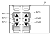
- FIG. 3 is a diagram showing an example of an icon display for the walk-in function.
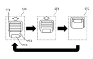
- FIG. 4 is a diagram showing an example of the first animation.
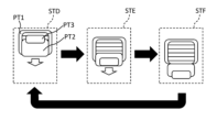
- FIG. 5 is a diagram showing an example of the second animation.
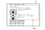
- FIG. 6 is a diagram showing an example of a message display.
- FIG. 7 is a diagram showing a time chart when the walk-in function is executed.
- FIG. 8 is a flowchart showing a processing procedure when the walk-in function is executed.
- FIG. 9 is a diagram showing an example of a user interface screen for the folding function.
- FIG. 10 is a diagram showing a time chart when the folding function is executed.
- FIG. 11 is a flowchart showing a processing procedure when the folding function is executed.
- FIG. 1 is a block diagram showing the configuration of a seat control device according to an embodiment of the present disclosure.
- the seat control device includes an operation display unit 10, a controller 20, and a drive unit 30.
- the controller 20 is connected to the operation display unit 10 and the controller 20 so that they can communicate with each other.
- the controller 20 and the operation display unit 10, and the controller 20 and the drive unit 30 are connected by a wired or wireless communication path.
- the drive unit 30 is mounted on the vehicle to adjust the seat mounted on the vehicle, but the operation display unit 10 and the controller 20 do not have to be mounted on the vehicle.
- the operation display unit 10 is a means for presenting information to the user and accepting input operations performed by the user by outputting a user interface screen generated by the controller 20 described below.
- the operation display unit 10 is composed of a touch panel and its control means, and a liquid crystal display and its control means.
- the touch panel and the liquid crystal display are composed of a single touch panel display.
- the operation display unit 10 displays the user interface screen generated by the controller 20.
- the drive unit 30 is a means for adjusting each part that constitutes the seat of the vehicle according to instructions from the controller 20, which will be described later.
- the drive unit 30 is provided in each seat of the vehicle, and adjusts the position and angle of each part that constitutes the seat.
- the drive unit 30 is an electric or hydraulic actuator, but is not limited to the examples given here. Examples of "each part that constitutes the seat” include the seat surface, backrest, headrest, armrest, footrest, etc.
- the drive unit 30 moves the seat in a first movement direction (toward the front of the vehicle). More specifically, the drive unit 30 moves the seat cushion forward and tilts the seat back forward.
- the walk-in function is a function that moves the seat toward the front of the vehicle in this way, making it easier for passengers to get in and out of the seat behind the seat.
- the drive unit 30 moves the seat in a second movement direction (towards the rear of the vehicle) opposite to the first movement direction. More specifically, the drive unit 30 moves the seat cushion backward and returns the seat back to the rear. For example, the drive unit 30 returns the position of the seat to the normal use state that has been registered in advance.
- the drive unit 30 folds the seat back. More specifically, the drive unit 30 tilts the seat back forward. For example, by executing the folding function in the rear seats of the vehicle, it is possible to secure rear space in the passenger compartment so that luggage can be loaded, etc.
- the drive unit 30 unfolds the seat backrest. More specifically, the drive unit 30 returns the seat backrest to its rearward position. For example, the drive unit 30 returns the position of the backrest to the normal use state that is registered in advance.
- the controller 20 (an example of a control unit or processing unit) is a general-purpose computer equipped with a CPU (central processing unit), memory, and input/output units.
- a computer program for functioning as part of the seat control device is installed in the controller 20. By executing the computer program, the controller 20 functions as multiple information processing circuits (21, 23, 25, 27, 29) equipped in the seat control device.
- the multiple information processing circuits (21, 23, 25, 27, 29) equipped in the seat control device are realized by software.
- the multiple information processing circuits (21, 23, 25, 27, 29) may be configured by individual hardware.
- the information processing circuits (21, 23, 25, 27, 29) may be shared with electronic control units (ECUs) used for other vehicle-related controls.
- ECUs electronice control units
- the controller 20 includes multiple information processing circuits (21, 23, 25, 27, 29), including an icon setting unit 21, a screen setting unit 23, an operation acquisition unit 25, a drive instruction unit 27, and a status acquisition unit 29.
- the icon setting unit 21 sets icons to be set on the user interface screen.
- the icon setting unit 21 sets icons (seat icons) that correspond to a view of the seats of a vehicle from above, as shown in FIG. 2.
- FIG. 2 shows the seat arrangement of a vehicle with three rows of seats, and seat icon ST1 and seat icon ST2 are shown as seat icons corresponding to the second row of seats.
- the icon setting unit 21 may change the seat icon depending on the operating status of the walk-in function or the folding function. For example, when the seat is moved in a first movement direction, the icon setting unit 21 may display the seat icon with a first animation having a movement corresponding to the first movement direction. Also, when the seat is moved in a second movement direction, the icon setting unit 21 may display the seat icon with a second animation having a movement corresponding to the second movement direction.
- first animation refers to an animation that shows each part of the seat moving in a first movement direction.
- Figure 4 shows three of the multiple still images that make up the first animation.
- the first animation expresses the movement of each part of the seat in the first movement direction by repeating the seat icons STA, STB, and STC in sequence.
- the seat surface PT1, backrest PT2, and headrest PT3 are moving upward (first movement direction) in the drawing in the order of the seat icons STA, STB, and STC.
- the "second animation” is an animation that shows each part of the seat moving in the second movement direction.
- Figure 5 shows three of the multiple still images that make up the second animation.
- the second animation expresses the movement of each part of the seat in the second movement direction by repeating the seat icons STD, STE, and STF in sequence.
- the seat surface PT1, backrest PT2, and headrest PT3 are moving downward (in the second movement direction) in the drawing in the order of the seat icons STD, STE, and STF.
- the icon setting unit 21 may set icons for operation buttons related to the walk-in function.
- the operation buttons related to the walk-in function include an execute button for executing the walk-in function, a release button for releasing the walk-in function, and a stop button for stopping the movement of the seat when the walk-in function is executed or released.
- the icon setting unit 21 may set an "execute icon” (first icon) corresponding to the execute button, a "release icon” (second icon) corresponding to the release button, and a "stop icon” corresponding to the stop button.
- FIG. 3 examples of the "execute icon,” “cancel icon,” and “stop icon” are shown.
- the execute icon BW11, the cancel icon BW12, and the stop icon BW19 are shown to execute the walk-in function of the seat icon ST1 shown in FIG. 2.
- the execute icon BW21, the cancel icon BW22, and the stop icon BW29 are shown to execute the walk-in function of the seat icon ST2 shown in FIG. 2.
- the "stop icon” may be placed between the “run icon” and the "cancel icon.”
- the icon setting unit 21 may change the icon of the operation button related to the walk-in function depending on the operating status of the walk-in function. For example, the icon setting unit 21 may highlight and display the execution icon while the seat is moving in a first movement direction. Also, the icon setting unit 21 may highlight and display the release icon while the seat is moving in a second movement direction.
- "highlighting" includes blinking of the icon (such as inverting the color or increasing or decreasing the brightness).
- the icon setting unit 21 may set icons for operation buttons related to the folding function.
- the operation buttons related to the folding function include a FOLD button for folding the backrest, an UNFOLD button for unfolding the backrest, and a STOP button for stopping folding/unfolding the backrest.
- the icon setting unit 21 may set a "FOLD icon” (third icon) corresponding to the FOLD button, an "UNFOLD icon” (fourth icon) corresponding to the UNFOLD button, and a "STOP icon” corresponding to the STOP button.
- FIG. 9 examples of the "FOLD icon”, "UNFOLD icon”, and “STOP icon” are shown.
- the FOLD icon BF1 the UNFOLD icon BF2
- the STOP icon BF3 are shown.
- the icon setting unit 21 may change the icon of the operation button related to the folding function according to the operating status of the folding function. For example, the icon setting unit 21 may highlight and display the FOLD icon while the backrest is tilted in the first movement direction. The icon setting unit 21 may also highlight and display the UNFOLD icon while the backrest is returned to the second movement direction.
- "highlighting" includes blinking of the icon (such as inverting the color or increasing or decreasing the brightness).
- the icon setting unit 21 may change the icon of the operation button related to the walk-in function or folding function depending on the status of the vehicle's shift range.
- the icon setting unit 21 may set the execute icon, release icon, and stop icon for display when the vehicle's shift range is P range (parking range). And, when the vehicle's shift range is other than P range, the icon setting unit 21 may change the execute icon, release icon, and stop icon to not be displayed, or to a display state indicating inoperability. For example, the "display state indicating inoperability" may be grayed out.
- the icon setting unit 21 may set the FOLD icon, UNFOLD icon, and STOP icon for display when the vehicle's shift range is P range (parking range). And, when the vehicle's shift range is other than P range, the icon setting unit 21 may change the FOLD icon, UNFOLD icon, and STOP icon to not be displayed, or to a display state indicating inoperability. For example, the "display state indicating inoperability" may be grayed out.
- the screen setting unit 23 combines the various icons set or changed by the icon setting unit 21 to set a user interface screen.
- the set user interface screen is displayed on the operation display unit 10.
- the screen setting unit 23 sets a user interface screen 51 for the walk-in function.
- FIG. 3 shows how an execution icon BW11, a release icon BW12, and a stop icon BW19 are arranged superimposed on the seat icon ST1 shown in FIG. 2.
- FIG. 3 also shows how an execution icon BW21, a release icon BW22, and a stop icon BW29 are arranged superimposed on the seat icon ST2 shown in FIG. 2.
- the screen setting unit 23 may arrange the seat icon that is the target of the walk-in function and the icon of the operation button related to the walk-in function of that seat icon so that they overlap or are adjacent to each other.
- the user interface screen 51 for the walk-in function is not limited to the examples given here.
- the screen setting unit 23 sets a user interface screen 53 for the folding function.
- FIG. 9 shows how a FOLD icon, an UNFOLD icon, and a STOP icon are arranged next to an array of seat icons.
- Check box icons CK1 to CK4 are shown superimposed on each of the seat icons ST1 to ST4.
- the check box icons CK1 to CK4 are displayed so that the user can switch between checking and unchecking them.
- the check box icons CK1 to CK4 are checked, they indicate that they will be subject to the folding function.
- the user interface screen 53 for the folding function is not limited to the examples given here.
- the screen setting unit 23 may set pop-up windows that display various messages on the user interface screen.
- the screen setting unit 23 may set a pop-up window that displays a message to the effect that seat adjustment cannot be performed when the vehicle's shift range is other than P range or when the vehicle is moving.
- a pop-up window that displays a message to the effect that seat adjustment cannot be performed when the vehicle's shift range is other than P range or when the vehicle is moving.
- an example of the first message is the message "Seat adjustment cannot be performed while the vehicle is moving.”
- the screen setting unit 23 may also set a pop-up window that displays a message that provides a hint regarding the operation when an operation is performed on the execution icon or the release icon for less than a predetermined time.
- a pop-up window that displays a message that provides a hint regarding the operation when an operation is performed on the execution icon or the release icon for less than a predetermined time.
- an example of the second message is the message "Press and hold to execute the walk-in function."
- the pop-up windows set by the screen setting unit 23 are not limited to the examples given here.
- the operation acquisition unit 25 acquires user input operations for various icons displayed on the operation display unit 10.
- the operation acquisition unit 25 acquires operations for each of the execute icon, the release icon, and the stop icon.
- an operation for the execute icon will be referred to as an execute operation (first operation), an operation for the release icon as a release operation (second operation), and an operation for the stop icon as a stop operation.
- the operation acquisition unit 25 acquires operations for each of the FOLD icon, UNFOLD icon, and STOP icon.
- the operation for the FOLD icon will be referred to as a folding operation (third operation), the operation for the UNFOLD icon as an unfolding operation (fourth operation), and the operation for the STOP icon as a folding stop operation.
- the operation acquisition unit 25 may also acquire the duration of the executed operation and the duration of the release operation.
- the drive instruction unit 27 generates a control signal for the drive unit 30 based on the acquired user input operation. That is, the drive instruction unit 27 generates a drive instruction to adjust the vehicle seat and outputs it to the drive unit 30.
- the drive instruction unit 27 moves the seat in a first movement direction based on an execution operation (first operation) on an execution icon (first icon).
- the drive instruction unit 27 also moves the seat in a second movement direction based on a release operation (second operation) on a release icon (second icon).
- the drive instruction unit 27 also stops the movement of the seat based on a stop operation on a stop icon.
- the drive instruction unit 27 may determine whether the duration of the execution operation is equal to or longer than a predetermined time (whether the first operation has been accepted for the predetermined time or longer). If the duration of the execution operation is equal to or longer than the predetermined time, the drive instruction unit 27 may start moving the seat in the first movement direction.
- the drive instruction unit 27 may also determine whether the duration of the release operation is equal to or longer than a predetermined time (whether the second operation has been accepted for the predetermined time or longer). If the duration of the release operation is equal to or longer than the predetermined time, the drive instruction unit 27 may start moving the seat in the second movement direction.
- the drive instruction unit 27 may stop the movement of the seat when a stop operation is received.
- the drive instruction unit 27 may continue the movement of the seat after starting the movement of the seat in the first movement direction until a stop operation is received or until the seat reaches the end position of the movement in the first movement direction. Whether or not the seat reaches the end position of the movement in the first movement direction may be acquired by the status acquisition unit 29 described later.
- the drive instruction unit 27 may continue the movement of the seat until a stop operation is received or until the seat reaches the end position of the movement in the second movement direction. Whether or not the seat reaches the end position of the movement in the second movement direction may be acquired by the status acquisition unit 29 described later.
- the drive instruction unit 27 may fold the backrest when a folding operation (third operation) on the FOLD icon (third icon) is received. Also, the drive instruction unit 27 may unfold the backrest when an unfolding operation (fourth operation) on the UNFOLD icon (fourth icon) is received.
- the status acquisition unit 29 acquires various vehicle statuses via sensors (not shown) and the like.
- the status acquisition unit 29 may acquire, via a position sensor, whether or not the seat is at the end position of movement in a first movement direction, or whether or not the seat is at the end position of movement in a second movement direction.
- the drive instruction unit 27 may acquire whether or not the vehicle's shift range is in the P range.
- the status acquisition unit 29 may acquire the position and angle of each part that constitutes the seat using a sensor (not shown).
- FIG. 7 is a diagram showing a time chart when the walk-in function is executed.
- the drive instruction unit 27 may start moving the seat in the first movement direction.
- the duration of the release operation is equal to or longer than a predetermined time
- the drive instruction unit 27 may start moving the seat in the second movement direction.
- the execute button or the cancel button is pressed at time T11 and continues to be pressed until time T13.
- time T12 a predetermined time ⁇ T1 has elapsed since time T11, the execution or cancellation of the walk-in function begins, and the seat moves.
- seat movement begins based on the continuation of the operation for a predetermined time period ⁇ T1 or longer, which prevents seat movement from beginning due to an incorrect operation.
- the drive instruction unit 27 when the drive instruction unit 27 receives a stop operation, it stops the movement of the seat. Even if the stop button is not pressed for the specified time ⁇ T1, the movement of the seat is immediately stopped, so that the user's intention to stop the seat can be immediately reflected in the adjustment of the seat.
- FIG. 8 is a flowchart showing a process for executing the walk-in function. For example, the process shown in FIG. 8 is repeatedly executed while the ignition key of the vehicle is turned on.
- step S101 the operation display unit 10 displays the user interface screen set by the screen setting unit 23.
- step S103 the operation acquisition unit 25 acquires the user's input operations for the various icons displayed on the operation display unit 10.
- step S105 the operation acquisition unit 25 determines whether or not an operation has been performed. If no operation has been performed (NO in step S105), the process returns to step S103.
- step S107 the screen setting unit 23 determines whether the vehicle's shift range is P range.
- step S109 the screen setting unit 23 displays a message indicating that seat adjustment operations are not possible.
- step S111 the drive instruction unit 27 determines whether the operation is a stop operation.
- step S113 the drive instruction unit 27 stops the movement of the seat.
- step S115 the drive instruction unit 27 determines whether the duration of the operation is equal to or longer than a predetermined time.
- step S117 the screen setting unit 23 displays a message that provides a hint regarding the operation.
- step S119 the drive instruction unit 27 determines whether the operation is an execution operation.
- step S121 the drive instruction unit 27 starts moving the seat in the first movement direction. In other words, the walk-in function is executed.
- step S123 the drive instruction unit 27 determines whether the operation is a release operation.
- step S125 the drive instruction unit 27 starts moving the seat in the second movement direction. In other words, the walk-in function is released.
- Fig. 10 is a diagram showing a time chart when the folding function is executed.
- the folding button or unfolding button is pressed at time T21 and released at time T22.
- the drive instruction unit 27 starts folding the backrest when it receives a folding operation.
- the drive instruction unit 27 starts unfolding the backrest when it receives an unfolding operation. Even if the folding button or unfolding button is not continuously pressed, the backrest is folded or unfolded instantly, so that the user's intention can be instantly reflected in the seat adjustment.
- FIG. 11 is a flowchart showing a processing procedure for executing the folding function. For example, the processing shown in FIG. 11 is repeatedly executed while the ignition key of the vehicle is turned on.
- step S201 the operation display unit 10 displays the user interface screen set by the screen setting unit 23.
- step S203 the operation acquisition unit 25 acquires the user's input operations for the various icons displayed on the operation display unit 10.
- step S205 the operation acquisition unit 25 determines whether or not an operation has been performed. If no operation has been performed (NO in step S205), the process returns to step S203.
- step S207 the screen setting unit 23 determines whether the vehicle's shift range is P range.
- step S209 the screen setting unit 23 displays a message indicating that seat adjustment operations are not possible.
- step S211 the drive instruction unit 27 determines whether the operation is a folding stop operation.
- step S213 the drive instruction unit 27 stops the folding or unfolding of the backrest.
- step S219 the drive instruction unit 27 determines whether the operation is a folding operation.
- step S221 the drive instruction unit 27 starts folding the backrest. In other words, it executes the folding function.
- step S223 the drive instruction unit 27 determines whether the operation is an unfolding operation.
- step S225 the drive instruction unit 27 starts unfolding the backrest. In other words, it cancels the folding function.
- the seat control method and the seat control device display, on an operation display unit, a seat icon indicating a seat installed in a vehicle, a first icon indicating a first movement direction of the seat when the walk-in function of the seat is activated, a second icon indicating a second movement direction opposite to the first movement direction, and a stop icon disposed between the first and second icons. Then, the seat is moved in the first movement direction based on a first operation on the first icon, the seat is moved in the second movement direction based on a second operation on the second icon, and the movement of the seat is stopped based on a stop operation on the stop icon.
- the user can understand the operation content by the icon. Also, since the stop icon is placed between the first icon and the second icon, the user can understand the operation content by the icon. As a result, the user can intuitively operate the icon and instruct the activation of the walk-in function of the seat installed in the vehicle.
- the seat control method and seat control device may also move the seat cushion forward and tilt the seat back forward when moving the seat in the first movement direction using the walk-in function. This allows the command to move the seat cushion and backrest associated with the walk-in function to be realized with a single operation.
- the seat control method and seat control device may display a seat icon using a first animation having a movement corresponding to the first movement direction when the seat is moved in a first movement direction.
- the seat icon may be displayed using a second animation having a movement corresponding to the second movement direction. This allows the user to understand that the seat is moving. Furthermore, the user can also understand the direction in which the seat is moving.
- the seat control method and seat control device may also start the movement of the seat in a first movement direction when a first operation is received for a predetermined time or more.
- the seat may also start the movement of the seat in a second movement direction when a second operation is received for a predetermined time or more. Since the seat movement starts based on the continuation of an operation for a predetermined time or more, the initiation of seat movement due to an erroneous operation is suppressed. From the driver's seat or passenger seat that operates the operation display unit, it may be difficult to see the area around the feet of the seat that is the target of the walk-in function, and preventing erroneous operation improves user convenience.
- the seat control method and seat control device may continue the movement of the seat after starting the movement of the seat in a first movement direction until a stop operation is received or until the seat reaches the end position of the movement in the first movement direction. After starting the movement of the seat in a second movement direction, the seat may continue the movement until a stop operation is received or until the seat reaches the end position of the movement in the second movement direction. This allows the seat to continue moving even after the user touches the operation display unit, preventing operations from becoming complicated when implementing the walk-in function.
- the seat control method and seat control device may also stop the movement of the seat when a stop operation is received. This allows the movement of the seat to be immediately stopped based on the stop operation performed via the operation display unit, and the user's intention to stop the seat can be immediately reflected in the adjustment of the seat.
- the seat control method and seat control device may display the first icon in an emphasized manner while the seat is moving in the first movement direction.
- the second icon may be displayed in an emphasized manner while the seat is moving in the second movement direction. This allows the user to understand that the seat is moving. Furthermore, the user can also understand the direction in which the seat is moving.
- the seat control method and seat control device may display the first icon and the second icon when the vehicle's shift range is in the P range.
- the first icon and the second icon may be changed to not be displayed or to a display state indicating that they are inoperable. This allows the user to understand that control of seat movement is possible when the vehicle is in the P range. Also, control of seat movement is suppressed when the vehicle is in a range other than the P range. Furthermore, the user can understand that control of seat movement is not possible when the vehicle is in a range other than the P range.
- the seat control method and seat control device may display a third icon relating to folding the seat backrest and a fourth icon relating to unfolding the seat backrest on the operation display unit.
- a third operation on the third icon is received, the seat backrest may be folded, and when a fourth operation on the fourth icon is received, the seat backrest may be unfolded.
- the backrest can be folded or unfolded instantly based on the folding or unfolding operation performed via the operation display unit, and the user's intention can be instantly reflected in the adjustment of the backrest.
- a situation where it is difficult to see the foot area of the seat that is the target of the walk-in function from the driver's seat or passenger seat operating the operation display unit a situation where it is difficult to see the backrest of the seat that is to be folded or unfolded is unlikely to occur. Therefore, there is little need to fold or unfold the backrest based on continued operation for more than a specified period of time.
- Processing circuits include programmed processors, electrical circuits, and even devices such as application specific integrated circuits (ASICs), and circuit components arranged to perform the described functions.
- ASICs application specific integrated circuits
Landscapes
- Engineering & Computer Science (AREA)
- Aviation & Aerospace Engineering (AREA)
- Transportation (AREA)
- Mechanical Engineering (AREA)
- Seats For Vehicles (AREA)
- User Interface Of Digital Computer (AREA)
Priority Applications (3)
| Application Number | Priority Date | Filing Date | Title |
|---|---|---|---|
| JP2025523752A JPWO2024247117A1 (https=) | 2023-05-30 | 2023-05-30 | |
| CN202380098396.5A CN121219165A (zh) | 2023-05-30 | 2023-05-30 | 座椅控制方法和座椅控制装置 |
| PCT/JP2023/020128 WO2024247117A1 (ja) | 2023-05-30 | 2023-05-30 | 座席制御方法及び座席制御装置 |
Applications Claiming Priority (1)
| Application Number | Priority Date | Filing Date | Title |
|---|---|---|---|
| PCT/JP2023/020128 WO2024247117A1 (ja) | 2023-05-30 | 2023-05-30 | 座席制御方法及び座席制御装置 |
Publications (1)
| Publication Number | Publication Date |
|---|---|
| WO2024247117A1 true WO2024247117A1 (ja) | 2024-12-05 |
Family
ID=93657158
Family Applications (1)
| Application Number | Title | Priority Date | Filing Date |
|---|---|---|---|
| PCT/JP2023/020128 Ceased WO2024247117A1 (ja) | 2023-05-30 | 2023-05-30 | 座席制御方法及び座席制御装置 |
Country Status (3)
| Country | Link |
|---|---|
| JP (1) | JPWO2024247117A1 (https=) |
| CN (1) | CN121219165A (https=) |
| WO (1) | WO2024247117A1 (https=) |
Citations (3)
| Publication number | Priority date | Publication date | Assignee | Title |
|---|---|---|---|---|
| JP2009023390A (ja) * | 2007-07-17 | 2009-02-05 | Toyota Motor Corp | 操作装置 |
| CN207015199U (zh) * | 2017-07-26 | 2018-02-16 | 长春富维安道拓汽车饰件系统有限公司 | 汽车座椅的遥控调节记忆系统 |
| JP2019061141A (ja) * | 2017-09-27 | 2019-04-18 | トヨタ自動車株式会社 | 表示制御装置 |
-
2023
- 2023-05-30 JP JP2025523752A patent/JPWO2024247117A1/ja active Pending
- 2023-05-30 WO PCT/JP2023/020128 patent/WO2024247117A1/ja not_active Ceased
- 2023-05-30 CN CN202380098396.5A patent/CN121219165A/zh active Pending
Patent Citations (3)
| Publication number | Priority date | Publication date | Assignee | Title |
|---|---|---|---|---|
| JP2009023390A (ja) * | 2007-07-17 | 2009-02-05 | Toyota Motor Corp | 操作装置 |
| CN207015199U (zh) * | 2017-07-26 | 2018-02-16 | 长春富维安道拓汽车饰件系统有限公司 | 汽车座椅的遥控调节记忆系统 |
| JP2019061141A (ja) * | 2017-09-27 | 2019-04-18 | トヨタ自動車株式会社 | 表示制御装置 |
Also Published As
| Publication number | Publication date |
|---|---|
| JPWO2024247117A1 (https=) | 2024-12-05 |
| CN121219165A (zh) | 2025-12-26 |
Similar Documents
| Publication | Publication Date | Title |
|---|---|---|
| JP4701278B2 (ja) | モニタ位置調整装置 | |
| CN104972931B (zh) | 用于声控座椅调节的系统和方法 | |
| US10661682B2 (en) | Vehicle seat haptic system and method | |
| EP3543061B1 (en) | Vehicular display device | |
| WO2007141628A2 (en) | Vehicle input device | |
| CN106064592B (zh) | 用于操作车窗的设备和方法 | |
| CN108136908B (zh) | 用于在车辆中操作至少一个功能的方法和操作系统 | |
| JP6896416B2 (ja) | 車載システム | |
| JP2018184024A (ja) | ディスプレイ可動方法及びディスプレイ可動装置 | |
| US20160224108A1 (en) | Methods and system for operating at least one display device of a motor vehicle, and motor vehicle comprising a system for operating at least one display device | |
| JP2011143885A (ja) | 車両用シート調整装置 | |
| WO2024247117A1 (ja) | 座席制御方法及び座席制御装置 | |
| CN106102682A (zh) | 机动车辆座椅按摩功能的控制方法和实施这种方法的系统 | |
| US20160121795A1 (en) | Side mirror system for automotive vehicles | |
| CN112824141B (zh) | 车辆座椅的折叠控制装置及控制方法 | |
| JP2011148450A (ja) | 車両用シート調整装置 | |
| JP7532143B2 (ja) | 表示制御装置および表示制御方法 | |
| JP2008065519A (ja) | 車載装置 | |
| CN111806463B (zh) | 用于展现交通工具的操作模式切换的方法和系统 | |
| WO2024006621A1 (en) | Multi-user control systems | |
| US20260001570A1 (en) | Cockpit system and control system | |
| JP2021099574A (ja) | エージェントシステムおよびエージェントの制御装置 | |
| JP2008189124A (ja) | 車載機器の操作補助システム、操作補助方法。 | |
| JP7622683B2 (ja) | 車両用表示システム | |
| JP7797993B2 (ja) | シート制御システム |
Legal Events
| Date | Code | Title | Description |
|---|---|---|---|
| 121 | Ep: the epo has been informed by wipo that ep was designated in this application |
Ref document number: 23939595 Country of ref document: EP Kind code of ref document: A1 |
|
| ENP | Entry into the national phase |
Ref document number: 2025523752 Country of ref document: JP Kind code of ref document: A |
|
| NENP | Non-entry into the national phase |
Ref country code: DE |