WO2024242007A1 - 酵素センサー - Google Patents
酵素センサー Download PDFInfo
- Publication number
- WO2024242007A1 WO2024242007A1 PCT/JP2024/018075 JP2024018075W WO2024242007A1 WO 2024242007 A1 WO2024242007 A1 WO 2024242007A1 JP 2024018075 W JP2024018075 W JP 2024018075W WO 2024242007 A1 WO2024242007 A1 WO 2024242007A1
- Authority
- WO
- WIPO (PCT)
- Prior art keywords
- electrode
- substance
- enzyme
- working electrode
- concentration
- Prior art date
- Legal status (The legal status is an assumption and is not a legal conclusion. Google has not performed a legal analysis and makes no representation as to the accuracy of the status listed.)
- Ceased
Links
Images








Classifications
-
- G—PHYSICS
- G01—MEASURING; TESTING
- G01N—INVESTIGATING OR ANALYSING MATERIALS BY DETERMINING THEIR CHEMICAL OR PHYSICAL PROPERTIES
- G01N27/00—Investigating or analysing materials by the use of electric, electrochemical, or magnetic means
- G01N27/26—Investigating or analysing materials by the use of electric, electrochemical, or magnetic means by investigating electrochemical variables; by using electrolysis or electrophoresis
- G01N27/28—Electrolytic cell components
- G01N27/30—Electrodes, e.g. test electrodes; Half-cells
- G01N27/327—Biochemical electrodes, e.g. electrical or mechanical details for in vitro measurements
- G01N27/3271—Amperometric enzyme electrodes for analytes in body fluids, e.g. glucose in blood
- G01N27/3272—Test elements therefor, i.e. disposable laminated substrates with electrodes, reagent and channels
-
- C—CHEMISTRY; METALLURGY
- C12—BIOCHEMISTRY; BEER; SPIRITS; WINE; VINEGAR; MICROBIOLOGY; ENZYMOLOGY; MUTATION OR GENETIC ENGINEERING
- C12Q—MEASURING OR TESTING PROCESSES INVOLVING ENZYMES, NUCLEIC ACIDS OR MICROORGANISMS; COMPOSITIONS OR TEST PAPERS THEREFOR; PROCESSES OF PREPARING SUCH COMPOSITIONS; CONDITION-RESPONSIVE CONTROL IN MICROBIOLOGICAL OR ENZYMOLOGICAL PROCESSES
- C12Q1/00—Measuring or testing processes involving enzymes, nucleic acids or microorganisms; Compositions therefor; Processes of preparing such compositions
- C12Q1/001—Enzyme electrodes
-
- C—CHEMISTRY; METALLURGY
- C12—BIOCHEMISTRY; BEER; SPIRITS; WINE; VINEGAR; MICROBIOLOGY; ENZYMOLOGY; MUTATION OR GENETIC ENGINEERING
- C12Q—MEASURING OR TESTING PROCESSES INVOLVING ENZYMES, NUCLEIC ACIDS OR MICROORGANISMS; COMPOSITIONS OR TEST PAPERS THEREFOR; PROCESSES OF PREPARING SUCH COMPOSITIONS; CONDITION-RESPONSIVE CONTROL IN MICROBIOLOGICAL OR ENZYMOLOGICAL PROCESSES
- C12Q1/00—Measuring or testing processes involving enzymes, nucleic acids or microorganisms; Compositions therefor; Processes of preparing such compositions
- C12Q1/001—Enzyme electrodes
- C12Q1/005—Enzyme electrodes involving specific analytes or enzymes
- C12Q1/006—Enzyme electrodes involving specific analytes or enzymes for glucose
Definitions
- the present disclosure relates to an enzyme-based sensor for a specific substance (substance to be measured) and a method for measuring the concentration of the specific substance using the same.
- JP 64-88244 A Patent Document 1
- the steady-state potential ⁇ V ⁇ generated when protons generated by an enzyme reaction are captured by a proton-sensitive membrane on a working electrode is estimated from the rate of change of the initial potential to measure the substrate concentration.
- JP 2019-158650 A Patent Document 2 discloses providing an external resistor between the working electrode and the reference electrode in order to make the redox reaction of the redox substance reversible.
- JP 2023-553889 A Patent Document 3 discloses a method for measuring the substrate concentration from the time change in the potential between the working electrode and the reference electrode.
- the present disclosure provides, in one aspect, a method for producing a method for manufacturing a semiconductor device comprising: An enzyme sensor for measuring a concentration of a substance to be measured in a solution containing the substance, a working electrode and a reference electrode each of which is accessible to the solution; an enzyme and a redox substance that can be reversibly oxidized and reduced, each of which is immobilized on the working electrode; a dV/dt output mechanism capable of outputting a time differential value dV/dt of a potential difference between the reference electrode and the working electrode, which is generated by a change in concentration of an oxidant and a reductant in the redox substance caused by a reaction between the substance to be measured and the enzyme,
- the potential difference in this enzyme sensor shifts to the noble side when the redox substance is oxidized by the reaction between the analyte and the enzyme, and shifts to the negative side when the redox substance is reduced.
- the "concentration of the substance to be measured” includes not only the absolute value of the concentration of the substance to be measured but also the relative value, and is a concept that also includes, for example, the time derivative value dV/dt that is in a linear relationship with the absolute value of the substrate concentration and can be used to calculate the absolute value of the concentration of the substance to be measured.
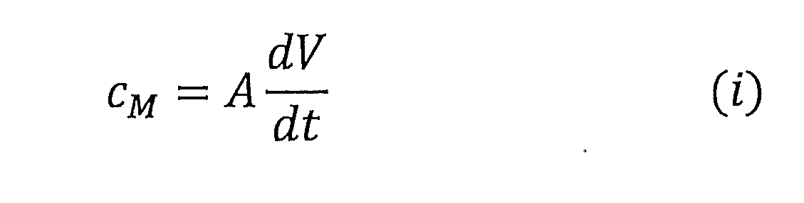
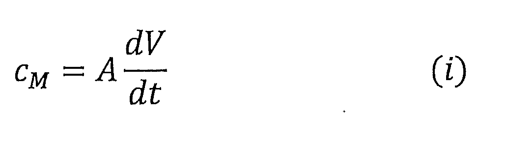
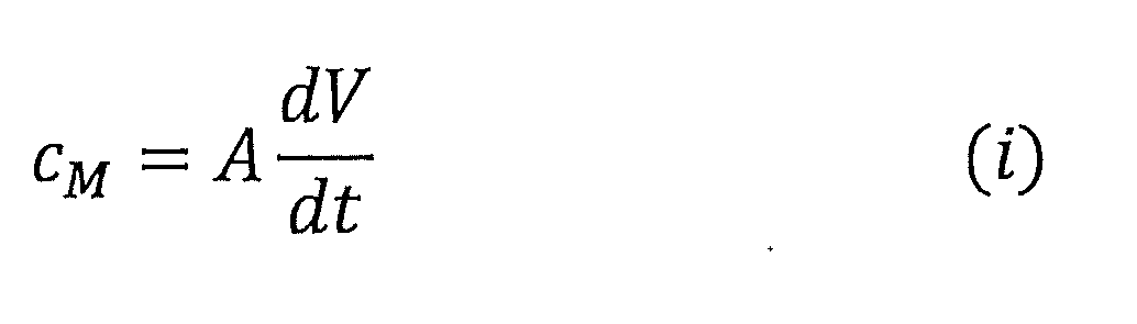
- the present disclosure provides a method for measuring a substance to be measured using the enzyme sensor of the present disclosure, bringing a solution containing the substance to be measured into contact with both the working electrode and the reference electrode; obtaining a time differential value dV/dt of a potential difference between the reference electrode and the working electrode over time in a state in which the working electrode and the reference electrode are electrically connected and no voltage is applied between the working electrode and the reference electrode; and calculating the concentration of the substance to be measured using the acquired time differential value dV/dt and the following linear function (i).
- V is the potential difference between the reference electrode and the working electrode
- t time
- C M is the concentration of the analyte
- A is a proportionality constant.
- the present disclosure provides a method for measuring another target substance using the enzyme sensor of the present disclosure,
- the electrode system of the enzyme sensor is a two-electrode system
- the working electrode and the counter electrode reference electrode
- the electrode system is a three-electrode system
- the working electrode, the counter electrode, and the reference electrode are brought into contact with a solution containing the substance to be measured.
- the electrode system of the enzyme sensor is the two-electrode system
- the working electrode and the counter electrode are electrically connected
- the electrode system is the three-electrode system
- the working electrode, the counter electrode and the reference electrode are electrically connected
- the potential of the working electrode reaches a predetermined potential set in advance, in either the two-electrode system or the three-electrode system, a predetermined voltage is applied between the counter electrode and the working electrode to allow a current to flow between the working electrode and the counter electrode, thereby returning the potential of the working electrode to a value before the start of measurement;
- the present disclosure provides a measurement system for measuring a concentration of a target substance in a solution containing the target substance, the system comprising:
- the measurement system includes an enzyme sensor, a signal processing mechanism, and a display unit.
- the enzyme sensor comprises: a working electrode and a reference electrode each of which is accessible to the solution; an enzyme and a redox substance that can be reversibly oxidized and reduced, each of which is immobilized on the working electrode; a measuring unit capable of measuring a potential difference between the reference electrode and the working electrode over time, the potential difference being generated by a change in concentration of an oxidant and a reductant in the redox substance caused by a reaction between the substance to be measured and the enzyme;
- the potential difference shifts to the noble side when the redox substance is oxidized by the reaction between the analyte and the enzyme, and shifts to the negative side when the redox substance is reduced.
- the signal processing mechanism calculates the concentration of the substance to be measured from the potential difference using the following linear function (i):
- the display unit relates to a measurement system capable of displaying the concentration of the substance to be measured calculated by the signal processing mechanism.
- V is the potential difference between the reference electrode and the working electrode
- t is time
- C M is the concentration of the analyte
- A is a proportionality constant.
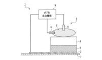
- FIG. 1 is a schematic diagram of an enzyme sensor according to one embodiment of the present disclosure.
- FIG. 2 is a schematic diagram of an enzyme sensor according to another embodiment of the present disclosure.
- FIG. 3 is a schematic diagram of an enzyme sensor according to another embodiment of the present disclosure.
- FIG. 4 is a schematic diagram of an enzyme sensor according to another embodiment of the present disclosure.
- FIG. 5 is a schematic diagram of an enzyme sensor according to another embodiment of the present disclosure.
- FIG. 6 is a schematic diagram of an enzyme sensor according to another embodiment of the present disclosure.
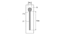
- FIG. 7 is a plan view of a working electrode formed on a substrate and used in Examples 1 to 7.
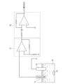
- FIG. 8 is a schematic diagram illustrating a substrate concentration measurement system used in Examples 1 and 4 to 7.
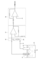
- FIG. 9 is a schematic diagram illustrating the substrate concentration measurement system used in Example 2.
- FIG. 10 is a schematic diagram illustrating the substrate concentration measurement system used in Example 3.
- FIG. 11 is a graph showing the time differential value of the working electrode potential that changes with time obtained in the experimental procedure of Example 1.
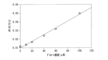
- FIG. 12 is a graph showing the relationship between the time differential value of the working electrode potential obtained in FIG. 11 and the glucose concentration.
- FIG. 13 is a graph showing the change in potential of the working electrode over time obtained in the experimental procedure of Example 2.
- FIG. 14 is a graph showing the relationship between the time derivative of the working electrode potential obtained in the experimental procedure of Example 2 and time.
- FIG. 15 is a graph showing the time differential value of the working electrode potential that changes with time obtained in the experimental procedure of Example 3.
- FIG. 16 is a graph showing the relationship between the time differential value of the working electrode potential obtained in FIG. 15 and the glucose concentration.
- the enzyme sensor disclosed in Patent Document 1 includes a working electrode on which an enzyme is immobilized on a pH-sensitive membrane, and utilizes the fact that the potential settles to a stationary potential (constant potential) over time.
- the enzyme sensor disclosed in Patent Document 1 avoids the problem of it taking time to settle to a stationary potential, which results in a long measurement time, and specifically, calculates ⁇ V ⁇ as an estimated value from a specific linear function to shorten the measurement time.
- this method has a problem in that it is not possible to measure the change in concentration of the measured substance in the measurement solution over time.
- ISFET ion-sensitive field effect transistor
- an enzyme sensor capable of measuring the change in concentration of a substance to be measured over time is produced by immobilizing a reversibly oxidizable and reducible redox substance and an enzyme on a working electrode, mediating the enzyme reaction with the redox substance, and measuring a signal obtained by amplifying the redox potential of the redox substance with an amplifier such as a field effect transistor.
- the reaction of the redox substance caused by the enzyme reaction is only in one direction, either oxidation or reduction, and as long as the enzyme reaction continues, the potential of the working electrode continues to rise or fall and does not settle at a constant potential, which is an irreversible problem.
- the working electrode and the reference electrode are connected by an external resistor to promote a spontaneous regeneration reaction (oxidation or reduction reaction) of the redox substance, which is an electron transfer mediator, thereby solving the above-mentioned irreversibility problem.
- the measurement accuracy is reduced because the reference electrode potential is changed by passing a current through the reference electrode, and there is also a problem that the reference electrode may be damaged by passing a current through the reference electrode.
- Patent Document 3 a potential is applied between the working electrode and the reference electrode, which serves as a standard electrode, for a short period of time before measuring the potential between the working electrode and the reference electrode, which complicates the relationship between the change in potential over time and the substrate concentration to be measured, making it difficult to incorporate a mechanism for determining the substrate concentration into the sensor.
- An object of the present disclosure in one aspect, is to provide an enzyme sensor capable of selectively measuring the concentration of a substance to be measured in a solution containing the substance, including changes over time, with high accuracy.
- the enzyme sensor of the present disclosure is an enzyme sensor for measuring the concentration of a substance to be measured (hereinafter also referred to as a "substrate") in a solution containing the substance.
- the enzyme sensor of the present disclosure includes a working electrode and a reference electrode, each of which can be in contact with the solution, an enzyme and a redox substance, each of which is immobilized on the working electrode, and a dV/dt output mechanism electrically connected to the working electrode and the reference electrode.
- the dV/dt output mechanism is capable of outputting a time differential value dV/dt of the potential difference between the reference electrode and the working electrode, which is generated by a change in concentration of the oxidant and the reductant in the redox substance caused by the reaction between the measured substance and the enzyme, over time.
- a time differential value dV/dt of the potential difference between the reference electrode and the working electrode which is generated by a change in concentration of the oxidant and the reductant in the redox substance caused by the reaction between the measured substance and the enzyme, over time.
- the charge generated by the reaction between the substrate and the enzyme can be transferred quickly and efficiently to the electrode via the oxidation-reduction substance, so that even when the substrate concentration is low and the product of the enzyme reaction is small, a sufficient signal (voltage) strength can be obtained in a short time in the enzyme sensor, and it is considered that the time-dependent change in the concentration of the substrate can be measured with high accuracy by calculating the differential value dV/dt of this signal with respect to time.
- the present disclosure provides an enzyme sensor that can selectively measure the concentration of the substance to be measured with high accuracy, including changes over time.
- the measurement target is glucose in Fig. 1 to Fig. 6, but the sensing target of the enzyme sensor of the present disclosure is not limited thereto.
- the enzyme sensor 1 of the present disclosure shown in FIG. 1 is a device for measuring the glucose concentration contained in a solution 6.
- the enzyme sensor 1 of the present disclosure includes a working electrode 2 to which an enzyme and a redox substance are immobilized, a sensing portion 8 including a counter electrode (reference electrode) 3, and a dV/dt output mechanism 9 electrically connected to the working electrode 2 and the counter electrode 3.
- the working electrode 2 and the counter electrode 3 can each be in contact with a solution 6 containing a substance to be measured, but the counter electrode 3 and the working electrode 2 are arranged so as not to be in electrical contact with each other.
- the enzyme is not dissolved in the solution 6, and the redox substance is insoluble in the solution 6.
- the enzyme is "not dissolved” in the solution 6 means that the enzyme is bound to the working electrode by adsorption or chemical bonding, so that even if the working electrode is brought into contact with the solution 6, the enzyme does not substantially migrate into the solution.
- the redox substance is "insoluble” in the solution 6 means that the solubility of the redox substance in the solution is low, and when the working electrode is brought into contact with the solution, the amount of reduction due to dissolution of the redox substance immobilized on the working electrode into the solution is substantially zero.
- the fact that the amount of reduction in the immobilized redox substance due to dissolution in the solution is substantially zero means that the solubility of the redox substance in the solution is 100 mg/L or less.
- the measurement of glucose concentration by the enzyme sensor 1 of the present disclosure is performed in a state where the working electrode 2 and the counter electrode 3 are in contact with the solution 6, the working electrode 2 and the counter electrode (reference electrode) 3 are electrically connected, and no voltage is applied to the working electrode 2 and the counter electrode 3, so that substantially no current flows.
- a state where substantially no current flows means a state where no current flows other than unintended leakage of current such as a leak current.
- the dV/dt output mechanism 9 outputs the rate of change with time of the potential difference generated between the counter electrode 3 and the working electrode 2 (hereinafter, the "rate of change with time of the potential difference” may also be referred to as the “time differential value dV/dt of the potential difference between the reference electrode and the working electrode” or simply as the “time differential value dV/dt”).
- the “potential difference between the reference electrode and the working electrode” is also called “OCV” (Open Circuit Voltage) or "natural potential”, and may also be called “potential of the working electrode” in this application.
- the "fixation" of the redox substance and the enzyme to the working electrode 2 means that the redox substance and the enzyme are in a state where they do not move relative to the working electrode 2.
- the redox substance is preferably directly fixed to the working electrode 2.
- the enzyme may be directly fixed to the working electrode 2 or indirectly fixed via the redox substance.
- the redox substance constitutes the redox layer 5 arranged in contact with the working electrode 2
- the enzyme constitutes the enzyme immobilized layer 4 arranged in contact with the redox layer.
- a mixture layer of the enzyme and the redox substance may be formed on the working electrode 2.
- the operation at the sensing site 8 will be described, taking as an example a case where the substance to be measured (substrate) is glucose.
- the enzyme glucose oxidase
- the working electrode 2 reacts with glucose in the presence of water and oxygen, glucose becomes gluconic acid and hydrogen peroxide is generated.
- the hydrogen peroxide oxidizes the reductant of the redox substance serving as the electron transfer mediator to an oxidant. This causes a change in the ratio of oxidant to reductant in the electron transfer mediator, and the potential difference between the counter electrode 3 and the working electrode 2 changes in response to this change.
- the enzyme sensor 1 of the present disclosure since the redox substance and the enzyme are immobilized on the working electrode 2, the charge generated by the reaction between the substrate and the enzyme can be transferred quickly and efficiently to the working electrode 2 via the redox substance. Therefore, even when the substrate concentration is low and the product of the enzyme reaction is small, the enzyme sensor 1 can obtain a sufficient signal (potential of the working electrode) strength in a short time, and by calculating the time differential value dV/dt of this signal, the change in the substrate concentration over time can be measured with high accuracy. For example, the signal can be measured even when the substrate concentration is several tens of ⁇ M (mol/L) or less. In addition, since the enzyme sensor 1 of the present disclosure utilizes an enzyme reaction, the substrate concentration can be measured selectively.
- the time derivative dV/dt of the potential difference between the reference electrode and the working electrode and the substrate concentration are in a linear relationship (first-order correlation), so the absolute value of the substrate concentration can be easily calculated from the measurement data of dV/dt.
- the enzyme sensor 1 of the present disclosure is equipped with a dV/dt output mechanism 9 that can output the dV/dt over time, so that the absolute value of the substrate concentration can be monitored over time.
- the enzyme does not dissolve in the solution 6, and the redox substance is insoluble in the solution 6, and each is fixed to the working electrode 2. Therefore, by applying a predetermined voltage between the working electrode 2 and the counter electrode 3 and passing a current between the working electrode 2 and the counter electrode 3, the ratio of oxidized and reduced substances can be appropriately controlled to a desired ratio. For example, when the oxidized form of the redox substance increases due to an enzyme reaction, the ratio of oxidized and reduced substances at the start of measurement can be restored by passing a current in the direction in which the oxidized form is reduced, thereby reducing the oxidized form. That is, in one embodiment, the enzyme sensor 1 of the present disclosure can be used repeatedly. Therefore, as shown in FIG. 2, in one embodiment, the enzyme sensor 1 of the present disclosure preferably further includes a circuit 10a that allows a current to flow between the working electrode 2 and the counter electrode 3 by applying a predetermined voltage between the counter electrode 3 and the working electrode 2 as necessary.
- the dV/dt output mechanism 9 capable of outputting the time differential value dV/dt may be, for example, one that can directly output dV/dt as a signal using an electric circuit such as a differential circuit (see Figures 8 to 10), or it may be one that is composed of a measuring device that measures the change in potential difference that occurs between the reference electrode 3 and the working electrode 2 due to the change in concentration of the oxidant and reductant in the redox substance resulting from the reaction between the substrate and the enzyme, an A/D converter that A/D converts the potential difference, and a central processing unit (CPU) that includes a calculation unit that calculates dV/dt from the obtained digital signal.
- the dV/dt output mechanism 9 may be any type that can output the time differential value dV/dt.
- the enzyme reaction oxidizes the substrate to generate an oxidizing agent such as hydrogen peroxide, which then oxidizes the redox substance in the electrode.
- the rate at which the redox substance is oxidized is expressed by the following formula based on chemical reaction kinetics:
- C o is the concentration of the oxidized form of the redox substance
- C R is the concentration of the reduced form of the redox substance
- k is the reaction rate constant
- C is the concentration of the oxidant
- t time.
- the meanings of these symbols are the same for the following formulas (2) to (9) and the following linear functions (i) to (ii).
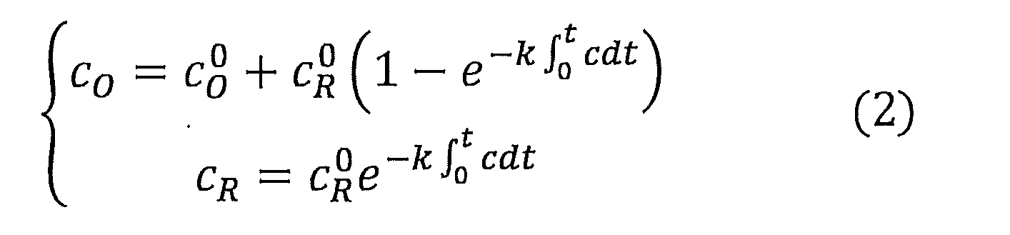
- the concentrations of the oxidized and reduced forms of the redox substance can be obtained as shown in equation (2).
- C 0 O is the initial concentration of the oxidized form of the redox substance
- C 0 R is the initial concentration of the reduced form of the redox substance.
- the meanings of these symbols are the same in the following formulas (3) to (9).
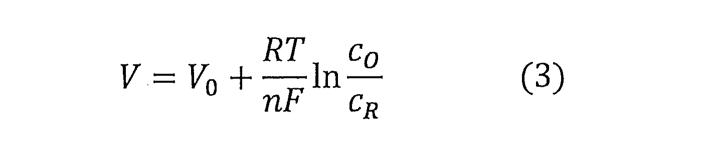
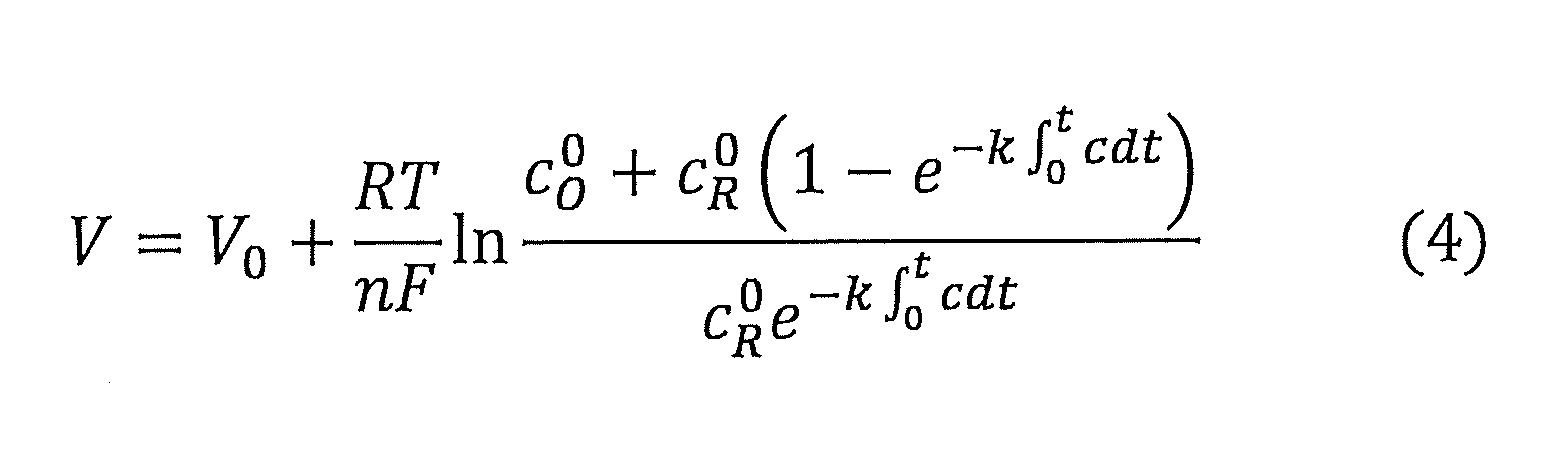
- the potential difference between the working electrode 2 and the reference electrode 3 is expressed by the Nernst equation, which gives the potential of an electrode on which an oxidation-reduction substance is immobilized, as shown in equation (3).
- R is the gas constant
- T is temperature (K)
- F is the Faraday constant
- n is the number of electrons transferred in the redox reaction of one molecule of oxidant
- V0 is the standard redox potential of the redox substance.
- V is the potential of the working electrode 2 that changes with the change in the concentrations of the oxidant and reductant of the redox substance.
- the meanings of these symbols are the same for the following formulas (4) to (9) and the following linear functions (i) to (ii).
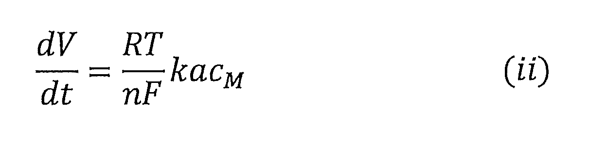
- equation (6) the time differential value dV/dt of the potential difference between the working electrode 2 and the reference electrode 3 is linearly related to the oxidant concentration. Furthermore, since the oxidant is generated by the enzyme reaction, the oxidant concentration can be considered to be a constant value corresponding to the substrate concentration if the oxidant is in a steady state where it diffuses into the solution and does not remain on the electrode surface.
- the reaction rate of the enzyme is accurately described by the Michaelis-Menten equation, but the reaction rate of the enzyme can be considered to be proportional to the concentration of the analyte (substrate) as long as the concentration of the analyte (substrate) is not high. Therefore, the concentration of the oxidant generated by the enzyme reaction can be considered to be proportional to the substrate concentration, so that the time differential value dV/dt of the potential difference between the working electrode 2 and the reference electrode 3 can be considered to be proportional to the substrate concentration, as shown in equation (7).
- C M is the concentration of the analyte (substrate).
- a is a proportional constant between the oxidant concentration and the substrate concentration.
- the meaning of this symbol is the same for the following formulas (8) and (9) and the following linear functions (i) and (ii).
- the enzyme reaction rate is slower than the diffusion rate of the substrate in the solution.
- the diffusion rate of the substrate is proportional to the substrate concentration, so the oxidant concentration is also proportional to the substrate concentration, and the rate of change over time of the potential difference generated between the counter electrode (reference electrode) 3 and the working electrode 2 is still proportional to the substrate concentration.
- the proportionality constant A in equation (8) is as shown in equation (9) below.
- the value of A may be determined experimentally.
- the time derivative (dV/dt) of the potential difference between the working electrode 2 and the reference electrode 3 is proportional to the substrate concentration.
- the redox substance is not oxidized or reduced directly by the enzyme, but is oxidized or reduced by the product generated by the enzyme reaction.
- the enzyme sensor 1 of the present disclosure includes a circuit 10a as a mechanism for applying a predetermined voltage between the working electrode 2 and the counter electrode (reference electrode) 3 as necessary to pass a current between the working electrode 2 and the counter electrode 3.
- This embodiment can be achieved, for example, by adding a circuit 10a as a switch, which is adjusted so that when a redox substance is oxidized due to a reaction between a substrate and an enzyme (enzyme reaction), the working electrode 2 and the counter electrode 3 are in a conductive state when the potential of the working electrode 2 exceeds a value slightly smaller than the potential at which the following linear function (ii) holds, and is in a non-conductive state when the potential of the working electrode 2 becomes equal to that of the counter electrode 3.
- a redox substance is reduced due to a reaction between a substrate and an enzyme (enzyme reaction)
- the same can be achieved by using a value for the potential of the working electrode 2 slightly larger than the potential at which the following linear function (ii) holds.
- the “slightly smaller value” is, for example, preferably 5 to 10% smaller than the potential at which the linear function (ii) above holds, and the “slightly larger value” is, for example, more preferably 5 to 10% larger than the potential at which the linear function (ii) above holds.
- the time for which the current is passed is preferably 1 second or more, more preferably 10 seconds or more, and even more preferably 20 seconds or more, from the viewpoint of sufficiently reducing or oxidizing the redox substance, and is preferably 300 seconds or less, more preferably 200 seconds or less, and even more preferably 100 seconds or less, in order to reduce the influence of interruption of the measurement time due to the current passing.
- the electrode system of the sensing site 8 may be a two-electrode system consisting of a working electrode 2 and a counter electrode (reference electrode) 3 as shown in Figures 1 and 2, but may also be a three-electrode system as shown in Figure 3.
- the electrode system of the enzyme sensor 1 of the present disclosure may be a three-electrode system further including a reference electrode 11 that can come into contact with a solution containing the substance to be measured, independent of the working electrode 2 and counter electrode 3.
- the reference electrode 11 functions as the reference electrode.
- the enzyme sensor 1 of the present disclosure may have the above-mentioned three-electrode system as the electrode system, and may further include, for example, a circuit 10b as a means for applying a predetermined voltage between the working electrode 2 and the counter electrode 3 to pass a current as necessary.
- the redox substance fixed to the working electrode 2 can be oxidized or reduced by applying a voltage between the working electrode 2 and the counter electrode 3 as necessary to pass a current through the circuit 10b.
- the potential of the working electrode 2 can be shifted to the negative side before the start of measurement to reduce the ratio of the oxidant at the start of measurement, thereby making it possible to measure the change in the concentration of the substrate over a longer period of time.
- the electrode system is the three-electrode system
- This embodiment can be implemented, for example, by adding a circuit 10b as a switch, which is adjusted so that when the redox substance is oxidized due to the reaction between the substrate and the enzyme (enzyme reaction), the circuit becomes conductive when the potential of the working electrode 2 exceeds a value slightly smaller than the potential at which the above linear function (ii) is established, and becomes non-conductive when the potential of the working electrode 2 becomes equal to the potential of the working electrode 2 at the start of measurement.
- the same implementation can be implemented by using a value slightly larger than the potential at which the above linear function (ii) is established.
- the “slightly smaller value” is, for example, preferably 5 to 10% smaller than the potential at which the linear function (ii) above holds, and the “slightly larger value” is, for example, preferably 5 to 10% larger than the potential at which the linear function (ii) above holds.
- the enzyme sensor 1 of the present disclosure may include a calculator 13 including a dV/dt output mechanism 9, a signal processing mechanism 16, and a display unit 12.
- the signal processing mechanism 16 is preferably a mechanism that calculates the absolute value of the concentration of the substrate corresponding to the time differential value dV/dt over time using the following linear function (i), but may also be a mechanism that displays the relative value of the concentration of the substrate.
- the display unit 12 may be an analog display unit or a digital display unit.
- the signal processing mechanism 16 includes a storage unit 15 and a central processing unit 14.
- the storage unit 15 includes a main storage unit (memory) 15a and an auxiliary storage unit (storage) 15b.
- the main storage unit 15a stores the following linear function (i) for calculating the absolute value of the concentration of the substrate from the time differential value dV/dt.
- a program for calculating the absolute value stored in the main storage unit 15a is executed by the central processing unit 14 such as a CPU including a calculation unit and a control unit, and the absolute value of the concentration of the substrate corresponding to the time differential value dV/dt is calculated over time from the following linear function (i).
- the calculated absolute value of the concentration of the substrate is recorded in the auxiliary storage unit 15b.
- the calculated absolute value of the concentration of the substrate may be digitally processed so that it can be displayed on the display unit 12 under the control of the control unit.
- the signal processing mechanism 16 may be configured to convert the voltage output by the dV/dt output mechanism 9, for example by resistive division, and display the converted voltage on a voltmeter (not shown) as an absolute or relative value of the concentration of the substrate calculated from the following linear function (i):
- the signal processing mechanism 16 may be configured in an analog manner in which the voltmeter (not shown) is an analog voltmeter whose scale indicates the concentration of the substrate calculated from the linear function (i).
- the dV/dt output mechanism 9 may include a measuring unit in the enzyme sensor 1 of the present disclosure shown in FIGS.
- the enzyme sensor 1 shown in Figures 1 to 5 includes a dV/dt output mechanism 9, but as shown in Figure 6, the enzyme sensor 100 of the present disclosure may be configured to include, instead of the dV/dt output mechanism 9, a measurement unit 101 that can measure the potential difference (OCV) between the reference electrode and the working electrode 2 over time, and a communications interface for transmitting digital information of the obtained potential difference to an external information processing terminal 102.
- a measurement unit 101 that can measure the potential difference (OCV) between the reference electrode and the working electrode 2 over time
- a communications interface for transmitting digital information of the obtained potential difference to an external information processing terminal 102.
- the measuring unit 101 is capable of measuring the potential difference (OCV) between the reference electrode 3 and the working electrode 2 over time, which is generated by the change in concentration of the oxidant and reductant in the redox substance resulting from the reaction between the substrate and the enzyme, when the working electrode 2 and the reference electrode 3 are electrically connected and no voltage is applied to the working electrode 2 and the counter electrode (reference electrode) 3, and no current is actually flowing.
- the potential difference (OCV) measured by the measuring unit 101 shifts to the noble side when the redox substance is oxidized by the reaction between the substrate and the enzyme, and shifts to the negative side when the redox substance is reduced.
- a potentiostat can be used as the measuring unit 101.
- the communication interface may be either wireless or wired.
- the communication interface refers to a means for transferring data from the enzyme sensor of the present disclosure to another device or system, and examples of wireless communication interfaces include Wi-Fi and Bluetooth (registered trademark) technology.
- the information processing terminal 102 is, for example, a digital electronic calculator capable of calculating the time differential value dV/dt of the potential difference, and includes, for example, a signal processing mechanism including a CPU (central processing unit) including a calculation unit and a control unit, a memory unit including memory and storage, an input unit, and a display unit.
- a signal processing mechanism including a CPU (central processing unit) including a calculation unit and a control unit, a memory unit including memory and storage, an input unit, and a display unit.
- the memory stores the linear function (i) for converting the time derivative dV/dt into the absolute value of the concentration of the substrate, and the CPU executes a program for calculating the absolute value of the substrate concentration stored in the memory, outputting the change over time in the absolute value of the substrate concentration corresponding to the time derivative dV/dt.
- the present disclosure provides in one aspect a method for producing a method for treating a cancer cell comprising: An enzyme sensor for measuring a concentration of a substance to be measured in a solution containing the substance, a working electrode and a reference electrode each of which is accessible to the solution; an enzyme and a redox substance that can be reversibly oxidized and reduced, each of which is immobilized on the working electrode; a measuring unit capable of measuring a potential difference between the reference electrode and the working electrode over time, the potential difference being generated by a change in concentration of an oxidant and a reductant in the redox substance caused by a reaction between the substance to be measured and the enzyme; a communication interface for transmitting the time differential value dV/dt of the potential difference to an external information processing terminal capable of calculating the time differential value dV/dt;
- the potential difference in this enzyme sensor shifts to the noble side when the redox substance is oxidized by the reaction between the analyte and the enzyme, and shifts to the negative side when the
- the present disclosure also provides, in one aspect, A measurement system for measuring a concentration of a substance to be measured in a solution containing the substance
- the measurement system includes an enzyme sensor, a signal processing mechanism, and a display unit.
- the enzyme sensor comprises: a working electrode and a reference electrode each of which is accessible to the solution; an enzyme and a redox substance that can be reversibly oxidized and reduced, each of which is immobilized on the working electrode; a measuring unit capable of measuring a potential difference between the reference electrode and the working electrode over time, the potential difference being generated by a change in concentration of an oxidant and a reductant in the redox substance caused by a reaction between the substance to be measured and the enzyme; The potential difference shifts to the noble side when the redox substance is oxidized by the reaction between the analyte and the enzyme, and shifts to the negative side when the redox substance is reduced.
- the signal processing mechanism calculates the concentration of the substance to be measured from the potential difference using the following linear function (i):
- the display unit relates to a measurement system capable of displaying the concentration of the substance to be measured calculated by the signal processing mechanism.
- V is the potential difference between the reference electrode and the working electrode
- t is time
- C M is the concentration of the analyte
- A is a proportionality constant.
- the dV/dt output mechanism 9 and the measuring unit 101 have a finite input impedance as long as they measure a potential difference, so a small current (leak current) flows through the working electrode 2 connected to them due to the load effect of the dV/dt output mechanism 9 or the measuring unit 101.
- a redox substance is oxidized by the reaction between the substrate and the enzyme (enzyme reaction)
- the oxidant is reduced by this small current
- a redox substance is reduced by the reaction between the substrate and the enzyme (enzyme reaction)
- the reductant is oxidized.
- the input impedance of the dV/dt output mechanism 9 or the measurement unit 101 is necessary to make the input impedance of the dV/dt output mechanism 9 or the measurement unit 101 sufficiently high in accordance with conventional methods and to make the microcurrent flowing through the working electrode 2 sufficiently small.
- the input impedance of the dV/dt output mechanism 9 or the measurement unit 101 can be easily set to a value large enough to ignore the load effect.
- the input impedance is preferably set, for example, so that the amount of redox substance reduced or oxidized by the current due to the load effect is 50% or less, preferably 10% or less, of the amount of redox substance oxidized or reduced by the enzyme reaction.
- the redox substance constituting the enzyme sensor 1 of the present disclosure is not particularly limited as long as it is a redox substance capable of transferring electrons to an electrode, and any conventionally known substance can be used.
- the redox substance include Prussian blue, Meldola blue, tetrathiafulvalene, quinones such as hydroquinone and 1,4-naphthoquinone, ferrocene, ferrocene derivatives, potassium ferrocyanide, ferricyanide, osmium complexes, p-aminophenol, and the like.
- the redox layer 5 can be formed by dropping or coating a solution containing a redox substance onto the working electrode 2 and then drying it.
- the solution is, for example, a dispersion liquid in which the redox substance is dispersed in a dispersion medium. Unfixed redox substances are preferably removed by washing, and pure water or a buffer solution can be used as the washing liquid.
- the total amount of redox substances fixed on the working electrode 2 is appropriately determined, for example, so that the above linear function (ii) holds during the desired measurement time, depending on the application (type of substrate) of the enzyme sensor 1 of the present disclosure.
- mixing a conductive material into the solution is preferable because it increases the conductivity of the redox layer 5.
- the type of reducing agent is not particularly limited as long as it can reduce the redox substance, and any known reducing agent can be used.
- reducing agents include thiol compounds such as mercaptopropanediol, mercaptoethanol, mercaptomethanol, and thiophenol, thiourea, ascorbic acid, oxalic acid, formic acid, gallic acid, uric acid, lithium aluminum hydride, sodium borohydride, and hydrazine.
- oxidizing agent there are no particular limitations on the type of oxidizing agent, so long as it can oxidize the redox substance, and any conventionally known oxidizing agent can be used.
- oxidizing agents include peroxides such as hydrogen peroxide, potassium nitrate, and chromic acid.
- the enzyme constituting the sensing portion 8 is not particularly limited as long as it is an enzyme that can donate and receive electrons through a reaction, and is appropriately applied depending on the sensing target (substrate), but an enzyme that selectively reacts with the substrate is preferable.
- the sensing target is glucose contained in blood, urine, etc.
- examples of the enzyme include glucose oxidase (GOD) and glucose dehydrogenase (GDH).
- an enzyme-modified electrode in which an enzyme and a redox substance are immobilized on the working electrode 2.
- the total amount of the redox substance and the total amount of the enzyme immobilized on the working electrode 2 are appropriately determined depending on the application (type of substrate) of the enzyme sensor of the present disclosure, for example, so that the above linear function (ii) holds true during the desired measurement time.
- the working electrode 2, the counter electrode 3, and the reference electrode 11, which is included as necessary, constituting the enzyme sensor 1 of the present disclosure each consist of, for example, a conductive layer formed on a substrate 7.
- the material of these conductive layers is selected taking into consideration the reaction products with the enzyme. Typically, metals such as gold, palladium, platinum, rhodium, indium, or iridium, carbon materials, etc. are mentioned. Gold or platinum is preferable, but a conductive material that does not react with the solution containing the measured substance may be used.
- the counter electrode 3 is platinum
- the working electrode 2 is gold
- the reference electrode 11 is a gold-Ag/AgCl electrode.
- the conductive layer is formed, for example, by evaporating these metals at any position on the substrate 7.
- a separately prepared metal thin film may be attached to the substrate 7 to form various electrodes.
- the conductive layer (electrode) may be formed by a conventionally known method such as vacuum deposition, electron beam, sputtering, plating, CVD, ion plating coating, inkjet, or printing, depending on the material.
- the counter electrode 3 may be formed using a metal wire or a metal plate without using the substrate and conductive layer.
- the reference electrode may also be formed by sealing a reference electrode material such as Ag/AgCl in a glass tube without using the substrate and conductive layer.
- an electrode that serves as a reference potential such as Ag/AgCl may be used as the counter electrode 3 in order to clarify the reference for the potential of the working electrode 2.
- the material of the substrate may be, for example, a sheet made of polyimide (PI) resin, polyester resin, polyamide resin, epoxy resin, polysulfone resin, or the like, or a film-like flexible material made of these.
- PI polyimide
- the measurement method of the present disclosure is a method for measuring the concentration of a substance to be measured (e.g., a biological substance) over time, and in one embodiment, includes at least the following steps (A) and (B).
- the measurement method of the present disclosure may further include step (C) in addition to steps (A) and (B).
- the time differential value dV/dt is acquired over time, so that the following steps (A) to (C) proceed almost simultaneously.
- a solution 6 containing the substance to be measured is brought into contact with both the working electrode and the reference electrode.
- step (B) The time derivative values dV/dt obtained in step (B) are converted to absolute values of the substrate concentration in step (C). Therefore, according to the measurement method disclosed herein, which includes steps (A) to (C), it is possible to measure the change over time in the absolute value of the substrate concentration.
- step (C) If you want to measure only the relative change in substrate concentration, you can skip step (C) and just use the time derivative value dV/dt obtained in step (B) as is.
- the above (C) may be performed by the enzyme sensor of the present disclosure or by an external information processing terminal.
- the above (B) includes obtaining the time differential value dV/dt and then transmitting the time differential value dV/dt to the external information processing terminal.
- step (D) When the potential of the working electrode reaches a predetermined potential, a predetermined voltage is applied between the working electrode and the counter electrode to pass a current between the working electrode and the counter electrode, thereby returning the potential of the working electrode to the value before the start of measurement.
- the above (D) can be performed whether the electrode system of the enzyme sensor is a two-electrode system consisting of a working electrode and a counter electrode, or a three-electrode system consisting of a working electrode, a counter electrode, and a reference electrode.
- the above (D) can be performed by the enzyme sensor including, as a switch, circuits 10a and 10b adjusted so that the working electrode and the counter electrode are in a conductive or non-conductive state depending on the potential of the working electrode.
- the continuous measurement time of the concentration of the analyte by the enzyme sensor of the present disclosure is, for example, the time at which the linear function (i) is established at most.
- the "predetermined potential” is a value slightly smaller than the potential of the working electrode 2 at which the linear function (i) holds when the redox substance is oxidized by the enzymatic reaction between the substrate and the enzyme, and a value slightly larger than the potential of the working electrode 2 at which the linear function (i) holds when the redox substance is reduced by the enzymatic reaction between the substrate and the enzyme.
- the "slightly smaller value” is, for example, a value that is preferably 5 to 10% smaller than the potential of the working electrode 2 at which the above linear function (i) holds
- the "slightly larger value” is, for example, a value that is preferably 5 to 10% larger than the potential of the working electrode 2 at which the above linear function (i) holds.
- the reference electrode is a reference electrode that constitutes a three-electrode system. That is, in this embodiment, the enzyme sensor includes a working electrode, a counter electrode, and a reference electrode (reference electrode).
- the enzyme sensor includes a working electrode, a counter electrode, and a reference electrode (reference electrode).
- the potential of the working electrode can be shifted to the negative side before the start of measurement to lower the ratio of oxidized form at the start of measurement, and the change in the concentration of the substrate over time can be measured for a longer period of time.
- the enzyme sensor disclosed herein can be used in any application that can utilize the substrate specificity of oxidoreductases, and examples of such applications include biosensors that sense organic substances or body fluids in biological samples, and biosensors that sense viruses or antibodies in environmental samples. More specifically, examples of such applications include blood glucose level sensors that measure the sugar concentration in blood, urine glucose level sensors that measure the sugar concentration in urine, lactate sensors that measure the lactate concentration in sweat, and virus sensors that exist in food, sewage, etc.
- Example 1 [Working electrode] Au was vacuum-deposited through a metal mask onto a substrate (polyimide film, 125 ⁇ m thick) 70 to a thickness of 50 nm, forming a working electrode 21 having the pattern shown in Fig. 7. Next, 5 ⁇ l of a mixed solution obtained by mixing a 0.2 wt % carbon nanotube aqueous dispersion (manufactured by TUBALL) and an aqueous solution containing 1 wt % Prussian blue (a redox material, manufactured by Aldrich) at a volume ratio of 10:1 was dropped onto a circular portion 21a of the working electrode 21 having a diameter of 3 mm, and the mixture was dried in a thermostatic chamber at 80°C for 10 minutes to form a carbon nanotube layer containing Prussian blue as a redox layer.
- a mixed solution obtained by mixing a 0.2 wt % carbon nanotube aqueous dispersion (manufactured by TUBALL) and an aque
- Counter electrode (reference electrode) A silver/silver chloride electrode was used as the counter electrode.
- the concentration of the substance to be measured was measured as follows. As shown in FIG. 8, an enzyme-modified electrode in which an enzyme and an oxidizing/reducing substance were immobilized on a working electrode 21 was connected to a non-inverting input terminal of a non-inverting amplifier circuit 27. The counter electrode 22 was connected to a ground potential. The enzyme-modified electrode and the counter electrode 22 were immersed in 10 mL of PBS solution (measurement solution), and the measurement solution was stirred at 500 rpm using a stirrer 24. First, measurement of the time differential value dV/dt of the potential of the working electrode 21 output by the differentiation circuit 28 was started.
- Example 2 [Working electrode] The working electrode 21 (see FIG. 9) and the enzyme-modified electrode including it were prepared in the same manner as in Example 1. [Counter electrode (reference electrode)] A copper electrode was used as the counter electrode 22 .
- the concentration of a substance to be measured was measured as follows. 9, an enzyme-modified electrode in which an enzyme and an oxidizing/reducing substance were immobilized on a working electrode 21 was connected to a counter electrode 22 by a switch 25 for controlling current flow and a power source 26 for applying a predetermined potential, and the enzyme-modified electrode was then connected to a non-inverting input terminal of a non-inverting amplifier circuit 27.
- the enzyme-modified electrode and counter electrode 22 were immersed in 10 mL of a PBS solution of 30 ⁇ M glucose (measurement solution), and the measurement solution was stirred at 500 rpm using a stirrer 24. Then, the following steps (1) to (3) were performed.
- the above steps (2) and (3) were repeated six times to obtain a graph showing the change in the potential of the working electrode 21 over time, as shown in Fig. 13. Furthermore, the time differential value of the potential of the working electrode 21 was measured by the differentiation circuit 28 connected to the non-inverting amplifier circuit 27, to obtain a graph showing a constant time differential value dV/dt with respect to the change in the potential of the working electrode 21 over time, as shown in Fig. 14. While a current is flowing between the working electrode 21 and the counter electrode 22, the measurement of the time differential value dV/dt of the potential of the working electrode 21 in Fig. 14 is stopped. The input impedance of the non-inverting input terminal of the non-inverting amplifier circuit 27 was 1 M ⁇ or more.
- Example 3 [Working electrode] The working electrode 29 (see FIG. 10) and the enzyme-modified electrode including it were prepared in the same manner as in Example 1. [Counter electrode] The counter electrode 30 was a platinum electrode. [Reference electrode (standard electrode)] The reference electrode 31 used was a silver/silver chloride electrode.
- FIG. 10 shows another embodiment of a system for measuring the concentration of a substance to be measured (substrate).
- a circuit 34 was used to control the potential of the counter electrode 30 so that the reference electrode 31 was at ground potential.
- An enzyme-modified electrode in which an enzyme and an oxidizing/reducing substance were immobilized on the working electrode 29 was connected to a switch 35 that applies a predetermined voltage to control the current flow between the working electrode 29 and the counter electrode 30 and a non-inverting input terminal of a non-inverting amplifier circuit 37.
- the enzyme-modified electrode, the counter electrode 30, and the reference electrode 31 were immersed in 10 mL of PBS solution.
- the PBS solution was stirred at 500 rpm using a stirrer 33, and then the switch 35 was closed for 100 seconds to first energize the working electrode 29 and the counter electrode 30.
- the potential of the working electrode 29 relative to the reference electrode 31 at this time was set to 0.015 V.
- the switch 35 was opened so that the working electrode 29 and the counter electrode 30 were not energized, and then the measurement of the time differential value dV/dt of the potential of the working electrode 29 output by the differentiation circuit 38 was started.
- Example 4 [Working electrode] The working electrode 21 (see FIG. 8) and the enzyme-modified electrode including it were prepared in the same manner as in Example 1. [Counter electrode (reference electrode)] The counter electrode 22 was a silver/silver chloride electrode. [Measurement of electrode potential and continuous measurement time] Using a measurement system as shown in FIG. 8, an enzyme-modified electrode in which an enzyme and an oxidizing/reducing substance were immobilized on a working electrode 21 was connected to a non-inverting input terminal of a non-inverting amplifier circuit 27. The counter electrode 22 was connected to a ground potential.
- the enzyme-modified electrode and the counter electrode 22 were immersed in 10 mL of a PBS solution (measurement solution), and the measurement solution was stirred at 500 rpm using a stirrer 24.
- the potential of the working electrode 21 output by the non-inverting amplifier circuit 27 was measured, and it was 0.015 V.
- the glucose concentration in the measurement solution was adjusted to 10 ⁇ M by adding 10 ⁇ L of a 100 mM D-glucose solution to the stirred PBS solution. After that, the time during which the time differential value dV/dt of the potential at which the linear function (i) holds could be continuously measured was measured, and it was 70 seconds.
- Example 5 [Working electrode]
- the working electrode 21 was prepared in the same manner as in Example 4.
- An enzyme-modified electrode was prepared in the same manner as in Example 1, except that 5 ⁇ l of a mixed solution obtained by mixing a 0.2 wt % carbon nanotube aqueous dispersion (manufactured by TUBALL) and an aqueous solution (Prussian blue content: 1 mass %) obtained by adding Prussian blue (redox material, manufactured by Aldrich) to an aqueous solution of ascorbic acid (reducing agent, manufactured by Tokyo Chemical Industry Co., Ltd.) adjusted to 100 mM was dropped onto a circular portion 21a having a diameter of 3 mm of the working electrode 21 (see FIG.
- the counter electrode 22 was a silver/silver chloride electrode. [Measurement of electrode potential and continuous measurement time] Using a measurement system as shown in FIG. 8, an enzyme-modified electrode in which an enzyme and an oxidizing/reducing substance were immobilized on a working electrode 21 was connected to a non-inverting input terminal of a non-inverting amplifier circuit 27. The counter electrode 22 was connected to a ground potential.
- the enzyme-modified electrode and the counter electrode 22 were immersed in 10 mL of PBS solution (measurement solution), and the measurement solution was stirred at 500 rpm using a stirrer 24.
- the potential of the working electrode 21 output by the non-inverting amplifier circuit 27 was measured, and it was ⁇ 0.05 V.
- the glucose concentration in the measurement solution was adjusted to 100 ⁇ M by adding 10 ⁇ L of 100 mM D-glucose solution to the stirred PBS solution. After that, the time during which the time differential value dV/dt of the potential at which the linear function (i) holds could be continuously measured was measured, and it was 200 seconds.
- Example 6 [Working electrode]
- the working electrode 21 was prepared in the same manner as in Example 4.
- An enzyme-modified electrode including the working electrode 21 was prepared in the same manner as in Example 4, except that 5 ⁇ l of a mixed solution obtained by mixing a 0.2 wt % carbon nanotube aqueous dispersion (manufactured by TUBALL) and an aqueous solution (Prussian blue content: 1 mass %) obtained by adding Prussian blue (redox material, manufactured by Aldrich) to an aqueous solution of 3-mercapto-1,2-propanediol (reducing agent, manufactured by Fuji Film Wako Pure Chemical Industries, Ltd.) adjusted to 50 mM in a volume ratio of 10:1 was dropped onto the circular portion 21a having a diameter of 3 mm of the working electrode 21.
- a mixed solution obtained by mixing a 0.2 wt % carbon nanotube aqueous dispersion (manufactured by TUBALL) and an aqueous solution (Prussian blue
- the molar ratio (reducing agent/redox material) of 3-mercapto-1,2-propanediol to Prussian blue was set to 5.0.
- the counter electrode 22 was a silver/silver chloride electrode. [Measurement of electrode potential and continuous measurement time] Using a measurement system as shown in FIG. 8, an enzyme-modified electrode in which an enzyme and an oxidizing/reducing substance were immobilized on a working electrode 21 was connected to a non-inverting input terminal of a non-inverting amplifier circuit 27. The counter electrode 22 was connected to a ground potential.
- the enzyme-modified electrode and the counter electrode 22 were immersed in 10 mL of a PBS solution (measurement solution), and the measurement solution was stirred at 500 rpm using a stirrer 24.
- the potential of the working electrode 21 output by the circuit 27 was measured, and found to be ⁇ 0.04 V.
- the glucose concentration in the measurement solution was adjusted to 100 ⁇ M by adding 10 ⁇ L of a 100 mM D-glucose solution to the stirred PBS solution. After that, the time during which the time differential value dV/dt of the potential at which the linear function (i) holds could be continuously measured was measured, and found to be 150 seconds.
- Example 7 [Working electrode]
- the working electrode 21 (see FIG. 8) was prepared in the same manner as in Example 4.
- An enzyme-modified electrode including the working electrode 21 was prepared in the same manner as in Example 4, except that 5 ⁇ l of a mixed solution obtained by mixing a 0.2 wt % carbon nanotube aqueous dispersion solution (manufactured by TUBALL) and an aqueous solution (Prussian blue content: 1 mass %) obtained by adding Prussian blue (redox material, manufactured by Aldrich) to an aqueous solution of thiourea (reducing agent, manufactured by Fuji Film Wako Pure Chemical Industries, Ltd.) adjusted to 10 mM in a volume ratio of 10:1 was dropped onto the circular portion 21a having a diameter of 3 mm of the working electrode 21.
- a mixed solution obtained by mixing a 0.2 wt % carbon nanotube aqueous dispersion solution (manufactured by TUBALL) and an aqueous solution (Prussian blue content
- the molar ratio of thiourea to Prussian blue (reducing agent/redox material) was 3.0.
- the counter electrode 22 was a silver/silver chloride electrode. [Measurement of electrode potential and continuous measurement time] Using a measurement system as shown in FIG. 8, an enzyme-modified electrode in which an enzyme and an oxidizing/reducing substance were immobilized on a working electrode 21 was connected to a non-inverting input terminal of a non-inverting amplifier circuit 27. The counter electrode 22 was connected to a ground potential. The enzyme-modified electrode and the counter electrode 22 were immersed in 10 mL of PBS solution (measurement solution), and the measurement solution was stirred at 500 rpm using a stirrer 24.
- the potential of the working electrode 21 output by the circuit 27 was measured, and it was ⁇ 0.02 V.
- the glucose concentration in the measurement solution was adjusted to 100 ⁇ M by adding 10 ⁇ L of 100 mM D-glucose solution to the stirred PBS solution. After that, the time during which the time differential value dV/dt of the potential at which the linear function (i) holds could be continuously measured was measured, and it was 100 seconds.
- Example 4 As can be seen from a comparison between Example 4 and Examples 5 to 7, by including a reducing agent in the redox layer in advance, the time period during which the time derivative dV/dt of the potential for which the linear function (i) is valid can be continuously measured can be extended.
- the measurement of substrate concentration using the enzyme sensor disclosed herein uses the potential of the working electrode, and does not require current to be passed through the working electrode or the solution containing the substance to be measured. This is useful, for example, when the substrate concentration is low (e.g., several tens of ⁇ M) or when the concentrations of multiple substrates are to be measured simultaneously.
Landscapes
- Chemical & Material Sciences (AREA)
- Life Sciences & Earth Sciences (AREA)
- Health & Medical Sciences (AREA)
- Organic Chemistry (AREA)
- Wood Science & Technology (AREA)
- Engineering & Computer Science (AREA)
- Zoology (AREA)
- Proteomics, Peptides & Aminoacids (AREA)
- Immunology (AREA)
- Biophysics (AREA)
- Analytical Chemistry (AREA)
- General Health & Medical Sciences (AREA)
- Molecular Biology (AREA)
- Physics & Mathematics (AREA)
- Biochemistry (AREA)
- Bioinformatics & Cheminformatics (AREA)
- Biotechnology (AREA)
- General Engineering & Computer Science (AREA)
- Microbiology (AREA)
- Genetics & Genomics (AREA)
- Emergency Medicine (AREA)
- Hematology (AREA)
- Chemical Kinetics & Catalysis (AREA)
- Electrochemistry (AREA)
- General Physics & Mathematics (AREA)
- Pathology (AREA)
- Apparatus Associated With Microorganisms And Enzymes (AREA)
- Measuring Or Testing Involving Enzymes Or Micro-Organisms (AREA)
Abstract
Description
被測定物質を含む溶液中の前記被測定物質の濃度を測定するための酵素センサーであり、
前記溶液に各々接しうる作用電極および基準電極と、
前記作用電極に各々固定された酵素および可逆的に酸化還元可能な酸化還元物質と、
前記被測定物質と前記酵素との反応に起因する前記酸化還元物質における酸化体と還元体の濃度変化によって生じる前記基準電極と前記作用電極との間の電位差の時間微分値dV/dtを経時的に出力可能とするdV/dt出力機構とを含み、
前記電位差は、前記酸化還元物質が前記被測定物質と前記酵素との反応により、酸化される場合には貴側にシフトし、還元される場合には卑側にシフトする、酵素センサーに関する。
尚、本開示において「被測定物質の濃度」は、被測定物質の濃度の絶対値のみならず相対値も含み、例えば、被測定物質の濃度の絶対値の算出に使用できる、基質濃度の絶対値と線形関係にある前記時間微分値dV/dtも含む概念である。
前記作用電極と前記基準電極の両方に前記被測定物質を含む溶液を接触させること、
前記作用電極と前記基準電極とが電気接続され、且つ、前記作用電極と前記基準電極との間に電圧を印可していない状態で、前記基準電極と前記作用電極の電位差の時間微分値dV/dtを経時的に得ること、
取得された前記時間微分値dV/dtと下記線形関数(i)を用いて前記被測定物質の濃度を算出すること、を含む被測定物質の測定方法に関する。

前記酵素センサーの電極系が、二電極系である場合、前記作用電極と前記対電極(基準電極)を、前記被測定物質を含む溶液を接触させ、三電極系である場合、前記作用電極と前記対電極と参照電極(基準電極)を、前記被測定物質を含む溶液を接触させること、
前記酵素センサーの電極系が、前記二電極系である場合は前記作用電極と前記対電極(基準電極)が電気接続され、前記三電極系である場合は前記作用電極と前記対電極と前記参照電極(基準電極)が電気接続され、前記作用電極の電位が予め設定された所定の電位に達すると、前記二電極系、前記三電極系のいずれにおいても、前記対電極と前記作用電極との間に所定の電圧を印可して、前記作用電極と前記対電極の間に電流を流し、前記作用電極の電位を測定開始前の値にもどすこと、
前記基準電極と前記作用電極の電位差の時間微分値dV/dtを経時的に得ること、
取得された前記時間微分値dV/dtと下記線形関数(i)を用いて前記被測定物質の濃度を算出すること、を含む被測定物質の測定方法に関する。

前記測定システムは、酵素センサーと信号処理機構と表示部とを含み、
前記酵素センサーは、
前記溶液に各々接しうる作用電極および基準電極と、
前記作用電極に各々固定された酵素および可逆的に酸化還元可能な酸化還元物質と、
前記被測定物質と前記酵素との反応に起因する前記酸化還元物質における酸化体と還元体の濃度変化によって生じる前記基準電極と前記作用電極との間の電位差を経時的に計測可能とする、計測部とを含み、
前記電位差は、前記酸化還元物質が前記被測定物質と前記酵素との反応により、酸化される場合には貴側にシフトし、還元される場合には卑側にシフトし、
前記信号処理機構は前記電位差から下記線形関数(i)を用いて前記被測定物質の濃度を算出し、
前記表示部は前記信号処理機構が算出した前記被測定物質の濃度を表示し得る、測定システムに関する。
本開示の酵素センサーは、前記溶液に各々接しうる作用電極および基準電極と、前記作用電極に各々固定された酵素および酸化還元物質と、前記作用電極および前記基準電極に電気的に接続されたdV/dt出力機構と、を含む。
前記dV/dt出力機構は、前記被測定物質と前記酵素との反応に起因する前記酸化還元物質における酸化体と還元体の濃度変化によって生じる前記基準電極と前記作用電極との間の電位差の時間微分値dV/dtを経時的に出力可能とする。そして、本開示の酵素センサーでは、前記酸化還元物質が前記被測定物質と前記酵素との反応により、酸化される場合には前記電位差が貴側にシフトし、還元される場合には前記電位差が卑側にシフトする。このような構成であることにより、本開示の酵素センサーは、下記の理由により、被測定物質の濃度を、経時変化も含めて選択的に高精度で測定できる。
しかし、電極上に酸化還元物質と酵素を固定化した測定系では、基質と酵素との反応(酵素反応)によって酸化還元物質が酸化もしくは還元されるが、作用電極電位は上昇または下降しつづけ、一定電位に落ち着くことがない。そのため、基質の濃度の経時的変化をモニタリングすることができない。しかし、酵素と酸化還元物質が電極に固定されていると、基質と酵素の反応により生じた電荷が酸化還元物質を介して電極に速やかに効率よく移動できるようになるため、基質濃度が低く酵素反応による生成物が少ない場合でも、酵素センサーにおいて短時間で十分な信号(電圧)強度が得られ、この信号の時間に対する微分値dV/dtを求めることにより、基質の濃度の経時変化を高精度で測定することができたと考えられる。
作用電極2に固定された酵素(グルコースオキシターゼ)が水および酸素の存在下でグルコースと反応することで、グルコースはグルコン酸となり、過酸化水素が生成される。同時に、当該過酸化水素により、電子伝達メディエータとしての酸化還元物質のうち、還元体が酸化体に酸化される。これにより電子伝達メディエータにおける酸化体と還元体の比率に変化が生じ、この変化に応じて対電極3と作用電極2の間の電位差が変化する。
ここでは、主として、基質と酵素との反応(酵素反応)により酸化還元物質が酸化される場合について説明するが、酸化還元物質が基質と酵素との反応(酵素反応)により還元される場合でも同様に説明される。



電流を流す時間は、酸化還元物質を十分に還元または酸化する観点から、好ましくは1秒以上、より好ましくは10秒以上、さらに好ましくは20秒以上であり、電流を流すことによる測定時間中断の影響を少なくするために、好ましくは300秒以下、より好ましくは200秒以下、さらに好ましくは100秒以下である。
前記信号処理機構16は、別の一態様において、dV/dt出力機構9が出力した電圧を、例えば抵抗分割等により電圧変換し、それを電圧計(図示せず。)に下記線形関数(i)から算出される前記基質の濃度の絶対値もしくは相対値として表示する構成であってもよい。
前記信号処理機構16は、さらに別の一態様において、前記電圧計(図示せず。)がアナログ電圧計であり、当該アナログ電圧計の目盛を、前記線形関数(i)から算出される基質の濃度で表示した、アナログ的な構成であってもよい。

また、図1~図5に示された酵素センサー1は、dV/dt出力機構9を含んでいるが、図6に示されるように、本開示の酵素センサー100は、dV/dt出力機構9に代えて、基準電極と作用電極2の間の電位差(OCV)を経時的に計測可能とする計測部101と、得られた電位差のデジタル情報を外部の情報処理端末102に送信するための通信用インターフェースを含む構成としてもよい。
被測定物質を含む溶液中の前記被測定物質の濃度を測定するための酵素センサーであり、
前記溶液に各々接しうる作用電極および基準電極と、
前記作用電極に各々固定された酵素および可逆的に酸化還元可能な酸化還元物質と、
前記被測定物質と前記酵素との反応に起因する前記酸化還元物質における酸化体と還元体の濃度変化によって生じる前記基準電極と前記作用電極との間の電位差を経時的に計測可能とする、計測部と、
前記電位差の時間微分値dV/dtを算出可能とする外部の情報処理端末に送信するための通信用インターフェースと、を含み、
前記電位差は、前記酸化還元物質が前記被測定物質と前記酵素との反応により、酸化される場合には貴側にシフトし、還元される場合には卑側にシフトする、酵素センサーに関する。
被測定物質を含む溶液中の前記被測定物質の濃度を測定するための測定システムであり、
前記測定システムは、酵素センサーと信号処理機構と表示部とを含み、
前記酵素センサーは、
前記溶液に各々接しうる作用電極および基準電極と、
前記作用電極に各々固定された酵素および可逆的に酸化還元可能な酸化還元物質と、
前記被測定物質と前記酵素との反応に起因する前記酸化還元物質における酸化体と還元体の濃度変化によって生じる前記基準電極と前記作用電極との間の電位差を経時的に計測可能とする、計測部とを含み、
前記電位差は、前記酸化還元物質が前記被測定物質と前記酵素との反応により、酸化される場合には貴側にシフトし、還元される場合には卑側にシフトし、
前記信号処理機構は前記電位差から下記線形関数(i)を用いて前記被測定物質濃度の濃度を算出し、
前記表示部は前記信号処理機構が算出した前記被測定物質の濃度を表示し得る、測定システムに関する。
[酸化還元物質]
本開示の酵素センサー1を構成する酸化還元物質としては、電極に電子を伝達できる酸化還元物質であれば特に制限はなく、従来公知のものを使用できる。酸化還元物質としては、例えば、プルシアンブルー、メルドラブルー、テトラチアフルバレン、ハイドロキノンや1,4-ナフトキノン等のキノン類、フェロセン、フェロセン誘導体、フェロシアン化カリウム、フェリシアン化物、オスミウム錯体、p-アミノフェノール等が挙げられる。
酵素反応によって酸化還元物質が酸化される場合、酸化還元物質層5には、酸化還元物質に加えて還元剤が予め含まれていると好ましい。酸化還元物質層に還元剤が予め含まれていると、測定開始時の作用電極の電位をより卑側に設定することができるため、上記線形関数(i)が成り立つ電位の時間微分値dV/dtをより長時間測定することできる。
酵素反応によって酸化還元物質が還元される場合、酸化還元物質層5には、酸化還元物質に加えて酸化剤が予め含まれていると好ましい。酸化還元物質層に酸化剤が予め含まれていると、測定開始時の作用電極の電位をより貴側に設定することができるため、上記線形関数(i)が成り立つ電位の時間微分値dV/dtをより長時間測定することできる。
センシング部位8を構成する酵素としては、反応により電子を授受できる酵素であれば特に制限はなく、センシング対象(基質)に応じて適宜適用されるが、基質と選択的に反応する酵素が好ましい。例えば、血液や尿等にふくまれるグルコースがセンシング対象である場合、酵素としては、グルコースオキシターゼ(GOD)やグルコースデヒドロゲナーゼ(GDH)等が挙げられる。そのほかにも生体液中に含まれるセンシング対象に応じて使用できる酵素として、乳酸オキシダーゼ、乳酸デヒドロゲナーゼ、ウレアーゼ、ウリカーゼ、アミノ酸オキシダーゼ、ビリルビンオキシダーゼ、コレステロールオキシダーゼ、アルコールオキシダーゼ、アルコールデヒドロゲナーゼ等が挙げられる。
本開示の酵素センサー1を構成する作用電極2、対電極3、必要に応じて含まれる参照電極11は、各々、例えば、基材7上に形成された導電層からなる。これらの導電層の材料は、酵素との反応生成物に配慮して選択される。典型的には、金、パラジウム、白金、ロジウム、インジウム又はイリジウム等の金属、炭素材料等が挙げられる。好ましくは金または白金であるが、被測定物質を含む溶液と反応を起こさない導電材料であってもよい。好ましくは、対電極3は白金、作用電極2は金、参照電極11は金にAg/AgCl電極を構成したものである。前記導電層は、例えば、基材7上の任意の位置にこれらの金属を蒸着等して形成される。または、別個に準備した金属薄膜を、基材7に貼り付けて、各種電極としてもよい。また、導電層(電極)は、材料に応じて、真空蒸着、電子線ビーム、スパッタリング、メッキ、CVD、イオンプレーティングコーティング、インクジェット、印刷などの、従来から公知の方法により形成されてもよい。対電極3は、前記基材および導電層を用いずに、金属ワイヤ―や金属板を用いて形成されたものであってもよい。参照電極も、前記基板および導電層を用いずに、ガラス管にAg/AgCl等の基準電極物質を封入したものでもよい。さらに、対電極3とは別に参照電極11を含まない二電極系では、作用電極2の電位の基準を明確化するために、対電極3にAg/AgCl等の基準電位となる電極を用いてもよい。
[基材]
上記基材の材料としては、例えば、ポリイミド(PI)樹脂、ポリエステル樹脂、ポリアミド樹脂、エポキシ樹脂、ポリサルフォン樹脂等から構成されるシートであってもよいし、これらからなるフィルム状のフレキシブル材料であってもよい。
次に、本開示の酵素センサーを用いた、本開示の被測定物質(センシング対象)の濃度の測定方法(以下「本開示の測定方法」と略称する場合もある。)について説明する。
本開示の測定方法は、工程(A)および(B)に加えて、さらに工程(C)を含んでいてもよい。
本開示の測定方法では、一態様において、経時的に時間微分値dV/dtを取得するので、下記(A)~(C)はほぼ同時進行する。
(A)作用電極と基準電極の両方に前記被測定物質を含む溶液6を接触させること。
(B)前記作用電極と前記基準電極とが電気接続され、且つ、作用電極及び基準電極に電圧を印加せず、実質的に電流が流れていない状態で、基準電極と作用電極との間の電位差の時間微分値dV/dtを経時的に得ること。
(C)前記時間微分値dV/dtを用いて、下記線形関数(i)から、前記時間微分値dV/dtに対応する前記基質の濃度の絶対値を得ること。

(D)作用電極の電位が予め設定された所定の電位に達すると、作用電極と対電極との間に所定の電圧を印加して作用電極と対電極との間に電流を流し、作用電極の電位を測定開始前の値に戻すこと。
上記(D)は、酵素センサーの電極系が、作用電極と対電極とからなる二電極系、又は、作用電極と対電極と参照電極とからなる三電極系のいずれであっても行える。上記(D)は、酵素センサーが、作用電極の電位に応じて作用電極と対電極とが導通状態または非導通状態になるように調整した回路10a,10bをスイッチとして含むことにより実行できる。
前記「予め設定された所定の電位」とは、基質と酵素との酵素反応により酸化還元物質が酸化される場合には、上記線形関数(i)が成立する作用電極2の電位より少し小さい値である。基質と酵素との酵素反応により酸化還元物質が還元される場合には、上記線形関数(i)が成立する作用電極2の電位より少し大きい値である。
[作用電極]
メタルマスクを通して、基材(ポリイミドフィルム、厚さ125μm)70の上に、Auを厚さが50nmとなるように真空蒸着して、図7に示されたパターンの作用電極21を形成した。次に、作用電極21のうちの直径が3mmの円形状部分21aの上に、0.2wt%のカーボンナノチューブ水分散溶液(TUBALL製)と1wt%プルシアンブルー(酸化還元物質、Aldrich製)を含む水溶液とを、体積比率10:1で混合した混合溶液を5μl滴下し、80℃の恒温槽内で10分間乾燥させて、プルシアンブルー含有のカーボンナノチューブ層を、酸化還元層として形成した。
対電極には、銀/塩化銀電極を使用した。
図8の測定系を用いて、下記の通り被測定物質(基質)の濃度の測定を行った。図8に示されるように、酵素と酸化還元物質が作用電極21に固定化された酵素修飾電極を非反転増幅回路27の非反転入力端子に接続した。対電極22はグランド電位になるように接続した。前記酵素修飾電極と対電極22を10mLのPBS溶液(被測定溶液)に浸漬させ、被測定溶液は撹拌子24を用いて500rpmで攪拌させた。まず、初めに微分回路28によって出力された作用電極21の電位の時間微分値dV/dtの計測を開始した。20秒後に攪拌しているPBS溶液に100mMのD-グルコース溶液を1μL添加することで測定溶液中のグルコース濃度を、10μMに調整した。その後、連続的にグルコース濃度を20μM、40μM、60μM、100μMと変化させたところ、図11に示すような、各グルコース濃度に対する作用電極21の電位の時間微分値dV/dtを連続的に計測したグラフを得た。
図11に示された、各グルコース濃度に対する時間微分値dV/dtから、図12に示されるように、グルコース濃度と時間微分値dV/dtとが比例関係となるプロット(検量線データ)を得た。このプロットは下記線形関数(i)と整合していた。そして、上記の外部の情報処理端末(デジタル式電子計算機)のメモリーに下記線形関数(i)を格納しておき、同じくメモリーに格納され当該線形関数(i)を用いて基質濃度の絶対値を算出するためのプログラムを実行することで、前記時間微分値dV/dtに対応するグルコース濃度を出力できた。
[作用電極]
作用電極21(図9参照)およびそれを含む酵素修飾電極は実施例1と同様にして作製した。
[対電極(基準電極)]
対電極22には銅電極を使用した。
図9の測定系を用いて、下記の通り、被測定物質(基質)の濃度の測定を行った。
図9に示されるように、酵素と酸化還元物質が作用電極21に固定化された酵素修飾電極と対電極22とを、通電を制御するスイッチ25と所定の電位を与える電源26で接続した後、前記酵素修飾電極を非反転増幅回路27の非反転入力端子に接続した。前記酵素修飾電極と対電極22を10mLの30μMのグルコースのPBS溶液(被測定溶液)に浸漬させ、被測定溶液は攪拌子24を用いて500rpmで攪拌させた。その後、下記(1)~(3)を行った。
(2)非反転増幅回路27で計測された作用電極21の電位が0.180Vに到達したら、スイッチ25を閉じて作用電極21と対電極22の間に0.115Vの電圧を10秒間印加して、作用電極21と対電極22を通電し、作用電極21の電位を0.115Vに戻した。
(3)作用電極21の電位が所定の値(0.115V)に戻ったら、直ちに作用電極21と対電極22が通電しないようにスイッチ25を開放した後、再び、非反転増幅回路27により作用電極21の電位変化を計測した。
なお、非反転増幅回路27の非反転入力端子の入力インピーダンスは1MΩ以上であった。
[作用電極]
作用電極29(図10参照)およびそれを含む酵素修飾電極は実施例1と同様にして作製した。
[対電極]
対電極30には白金電極を使用した。
[参照電極(基準電極)]
参照電極31には銀/塩化銀電極を使用した。
図10は、被測定物質(基質)の濃度の測定系の別の一態様である。
図10に示されるように、参照電極31がグランド電位になるように対電極30の電位を制御する回路34を用いた。所定の電圧を印加して作用電極29と対電極30との通電を制御するスイッチ35と非反転増幅回路37の非反転入力端子に、酵素と酸化還元物質が作用電極29に固定化された酵素修飾電極を接続した。前記酵素修飾電極と対電極30と参照電極31を10mLのPBS溶液に浸漬させた。PBS溶液は攪拌子33を用いて500rpmで攪拌させた後、まず、初めに作用電極29と対電極30とを通電するようにスイッチ35を100秒間閉じた。この時の参照電極31に対する作用電極29の電位を0.015Vとした。次に、作用電極29と対電極30とが通電しないようにスイッチ35を開放した後、微分回路38によって出力された作用電極29の電位の時間微分値dV/dtの計測を開始した。40秒後に攪拌しているPBS溶液に100mMのD-グルコース溶液を1μL添加することで測定溶液中のグルコース濃度を、10μMに調整した後に、連続的にグルコース濃度を30μM、50μM、75μM、100μM、200μMと変化させた。グルコース濃度が100μMのPBS溶液の計測中に作用電極電位が0.08Vに達したために、微分回路38による作用電極電位の時間微分の測定を停止し、作用電極29と対電極30とが通電するようにスイッチ35を80秒間閉じて、作用電極29の電位を0.015Vに戻した。作用電極29の電位が0.015Vに戻ったら、直ちに作用電極29と対電極30とが通電しないようにスイッチ35が開放され、微分回路38による作用電極29の電位の時間微分値dV/dtの計測が再開された。図15に示すように、各グルコース濃度に対する作用電極29の電位の時間微分値dV/dtが連続的に計測されたグラフを得た。さらにリアルタイムでグルコース濃度が計測可能であることが確認できた。
図15に示された、各グルコース濃度に対する時間微分値dV/dtから、図16に示されるように、グルコース濃度と時間微分値dV/dtとが比例関係となるプロット(検量線データ)を得た。このプロットは上記線形関数(i)と整合していた。そして、上記の外部の情報処理端末(デジタル式電子計算機)のメモリーに上記線形関数(i)を格納しておき、同じくメモリーに格納され上記線形関数(i)を用いて基質濃度の絶対値を算出するためのプログラムを実行することで、前記時間微分値dV/dtに対応するグルコース濃度を出力できた。
[作用電極]
作用電極21(図8参照)およびそれを含む酵素修飾電極は実施例1と同様にして作製した。
[対電極(基準電極)]
対電極22には、銀/塩化銀電極を使用した。
[電極電位の計測と連続測定可能時間の計測]
図8に示されるような測定系を用いて、酵素と酸化還元物質が作用電極21に固定化された酵素修飾電極を非反転増幅回路27の非反転入力端子に接続した。対電極22はグランド電位になるように接続した。前記酵素修飾電極と対電極22を10mLのPBS溶液(被測定溶液)に浸漬させ、被測定溶液は撹拌子24を用いて500rpmで攪拌させた。まず、初めに非反転増幅回路27によって出力された作用電極21の電位を計測したところ、0.015Vであった。次に攪拌しているPBS溶液に100mMのD-グルコース溶液を10μL添加することで測定溶液中のグルコース濃度を、10μMに調整した。その後、前記線形関数(i)が成り立つ電位の時間微分値dV/dtが連続的に測定可能な時間を計測したところ70秒であった。
[作用電極]
作用電極21(図8参照)は実施例4と同様にして作製した。
作用電極21(図7参照)のうちの直径が3mmの円形状部分21aの上に、0.2wt%のカーボンナノチューブ水分散溶液(TUBALL製)と、100mMに調整したアスコルビン酸(還元剤、東京化成工業社製)水溶液にプルシアンブルー(酸化還元物質、Aldrich製)を添加して得た水溶液(プルシアンブルーの含有量:1質量%)とを、体積比率10:1で混合した混合溶液を5μl滴下したこと以外は、実施例1と同様にして、酵素修飾電極を作製した。アスコルビン酸とプルシアンブルーのモル比(還元剤/酸化還元物質)は8.6とした。
[対電極(基準電極)]
対電極22には、銀/塩化銀電極を使用した。
[電極電位の計測と連続測定可能時間の計測]
図8に示されるような測定系を用いて、酵素と酸化還元物質が作用電極21に固定化された酵素修飾電極を非反転増幅回路27の非反転入力端子に接続した。対電極22はグランド電位になるように接続した。前記酵素修飾電極と対電極22を10mLのPBS溶液(被測定溶液)に浸漬させ、被測定溶液は撹拌子24を用いて500rpmで攪拌させた。まず、初めに非反転増幅回路27によって出力された作用電極21の電位を計測したところ、―0.05Vであった。次に攪拌しているPBS溶液に100mMのD-グルコース溶液を10μL添加することで測定溶液中のグルコース濃度を、100μMに調整した。その後、前記線形関数(i)が成り立つ電位の時間微分値dV/dtが連続的に測定可能な時間を計測したところ200秒であった。
[作用電極]
作用電極21(図8参照)は実施例4と同様にして作製した。
作用電極21のうちの直径が3mmの円形状部分21aの上に、0.2wt%のカーボンナノチューブ水分散溶液(TUBALL製)と、50mMに調整した3-メルカプト-1,2-プロパンジオール(還元剤、富士フィルム和光純薬社製)水溶液にプルシアンブルー(酸化還元物質、Aldrich製)を添加して得た水溶液(プルシアンブルーの含有量:1質量%)とを、体積比率10:1で混合した混合溶液を5μl滴下したこと以外は、実施例4と同様にして、作用電極21を含む酵素修飾電極を作製した。3-メルカプト-1,2-プロパンジオールとプルシアンブルーのモル比(還元剤/酸化還元物質)は5.0とした。
[対電極(基準電極)]
対電極22には、銀/塩化銀電極を使用した。
[電極電位の計測と連続測定可能時間の計測]
図8に示されるような測定系を用いて、酵素と酸化還元物質が作用電極21に固定化された酵素修飾電極を非反転増幅回路27の非反転入力端子に接続した。対電極22はグランド電位になるように接続した。前記酵素修飾電極と対電極22を10mLのPBS溶液(被測定溶液)に浸漬させ、被測定溶液は撹拌子24を用いて500rpmで攪拌させた。まず、初めに回路27によって出力された作用電極21の電位を計測したところ、―0.04Vであった。次に攪拌しているPBS溶液に100mMのD-グルコース溶液を10μL添加することで測定溶液中のグルコース濃度を、100μMに調整した。その後、前記線形関数(i)が成り立つ電位の時間微分値dV/dtが連続的に測定可能な時間を計測したところ150秒であった。
[作用電極]
作用電極21(図8参照)は実施例4と同様にして作製した。
作用電極21のうちの直径が3mmの円形状部分21aの上に、0.2wt%のカーボンナノチューブ水分散溶液(TUBALL製)と、10mMに調整したチオ尿素(還元剤、富士フィルム和光純薬社製)水溶液にプルシアンブルー(酸化還元物質、Aldrich製)を添加して得た水溶液(プルシアンブルーの含有量:1質量%)とを、体積比率10:1で混合した混合溶液を5μl滴下したこと以外は、実施例4と同様にして、作用電極21を含む酵素修飾電極を作製した。チオ尿素とプルシアンブルーのモル比(還元剤/酸化還元物質)は3.0とした。
[対電極(基準電極)]
対電極22には、銀/塩化銀電極を使用した。
[電極電位の計測と連続測定可能時間の計測]
図8に示されるような測定系を用いて、酵素と酸化還元物質が作用電極21に固定化された酵素修飾電極を非反転増幅回路27の非反転入力端子に接続した。対電極22はグランド電位になるように接続した。前記酵素修飾電極と対電極22を10mLのPBS溶液(被測定溶液)に浸漬させ、被測定溶液は撹拌子24を用いて500rpmで攪拌させた。まず、初めに回路27によって出力された作用電極21の電位を計測したところ、―0.02Vであった。次に攪拌しているPBS溶液に100mMのD-グルコース溶液を10μL添加することで測定溶液中のグルコース濃度を、100μMに調整した。その後、前記線形関数(i)が成り立つ電位の時間微分値dV/dtが連続的に測定可能な時間を計測したところ100秒であった。

2、21、29 作用電極
3、17、22、30 対電極
4 酵素固定化層
5 酸化還元物質層
6、19、23、32 測定溶液
7 基材
8 センシング部位
9 dV/dt出力機構
101 計測部
10a、10b 回路
11、31 参照電極
12 表示部
13 演算器
14 中央処理部
15 記録部
15a 主記録部
15b 補助記憶部
16 信号処理機構
20、24、33 攪拌子
25、35 作用極―対電極通電スイッチ
26、36 電源
27、37 非反転増幅回路
28、38 微分回路
34 回路
Claims (15)
- 被測定物質を含む溶液中の前記被測定物質の濃度を測定するための酵素センサーであり、
前記溶液に各々接しうる作用電極および基準電極と、
前記作用電極に各々固定化された酵素および可逆的に酸化還元可能な酸化還元物質と、
前記被測定物質と前記酵素との反応に起因する前記酸化還元物質における酸化体と還元体の濃度変化によって生じる前記基準電極と前記作用電極との間の電位差の時間微分値dV/dtを経時的に出力可能とするdV/dt出力機構とを含み、
前記電位差は、前記酸化還元物質が前記被測定物質と前記酵素との反応により、酸化される場合には貴側にシフトし、還元される場合には卑側にシフトする酵素センサー。 - 前記被測定物質と前記酵素との反応によって生成した生成物によって、前記酸化還元物質が酸化又は還元される、請求項1に記載の酵素センサー。
- 前記酵素が、前記反応により電子を授受できる酵素である、請求項1又は2に記載の酵素センサー。
- 前記時間微分値dV/dtから前記被測定物質の濃度の絶対値を算出するための下記線形関数(i)により、前記時間微分値dV/dtに対応する前記被測定物質の濃度の絶対値を経時的に算出する機構と、を含む、請求項1から3のいずれかの項に記載の酵素センサー。

- 前記作用電極上に前記酵素と前記酸化還元物質とが固定された酵素修飾電極は、
前記被測定物質と前記酵素との反応により前記酸化還元物質が酸化される場合は還元剤をさらに含み、
前記被測定物質と前記酵素との反応により前記酸化還元物質が還元される場合は酸化剤をさらに含む、請求項1から4のいずれかの項に記載の酵素センサー。 - 前記電位差は、前記酸化還元物質が前被測定物質と前記酵素との反応により酸化されて貴側にシフトする、請求項1から5のいずれかの項に記載の酵素センサー。
- 前記酵素センサーの電極系は、前記作用電極と対電極からなる二電極系、または、前記作用電極と対電極と参照電極からなる三電極系であり、
前記基準電極は、前記二電極系を構成する前記対電極、または前記三電極系を構成する前記参照電極である、請求項1から6のいずれかの項に記載の酵素センサー。 - 前記酸化還元物質は、前記作用電極に接して配置された酸化還元層を構成し、前記酵素は、前記酸化還元層に接して配置された酵素固定化層を構成している、請求項1から7のいずれかの項に記載の酵素センサー。
- 前記酸化還元層が導電性炭素材料を含む、請求項1から8のいずれかの項に記載の酵素センサー。
- 前記導電性炭素材料がカーボンナノチューブを含む、請求項9に記載の酵素センサー。
- さらに、前記二電極系、前記三電極系のいずれにおいても、前記対電極と前記作用電極との間に所定の電圧を印可して、前記作用電極と前記対電極の間に電流を流すことを可能とする回路を含む、請求項7に記載の酵素センサー。
- 算出された前記被測定物質の濃度の絶対値を表示する表示部をさらに含む、請求項4に記載の酵素センサー。
- 請求項1から12のいずれかに記載の酵素センサーを用いた被測定物質の測定方法であり、
前記作用電極と前記基準電極の両方に前記被測定物質を含む溶液を接触させること、
前記作用電極と前記基準電極とが電気接続され、且つ、前記作用電極と前記基準電極との間に電圧を印可していない状態で、前記基準電極と前記作用電極の電位差の時間微分値dV/dtを経時的に得ること、
取得された前記時間微分値dV/dtと下記線形関数(i)を用いて前記被測定物質の濃度を算出すること、を含む被測定物質の測定方法。
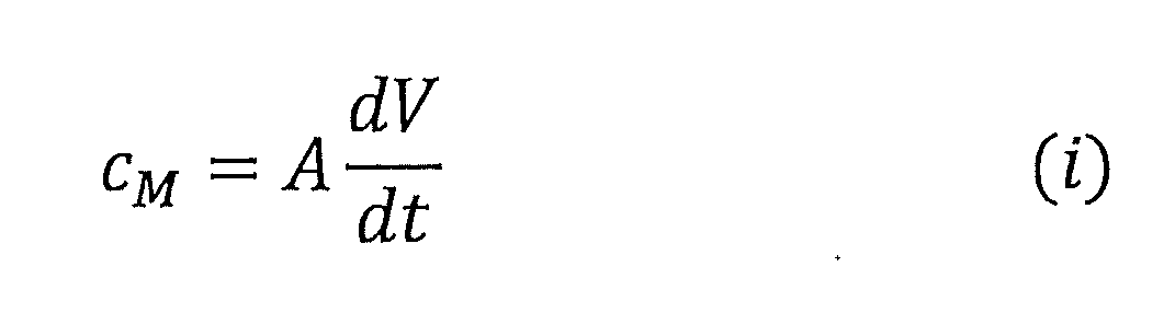
- 請求項11に記載の酵素センサーを用いた被測定物質の測定方法であり、
前記酵素センサーの電極系が、前記二電極系である場合は前記作用電極と前記対電極、前記被測定物質を含む溶液を接触させ、前記三電極系である場合は前記作用電極と前記対電極と前記参照電極を、前記被測定物質を含む溶液を接触させること、
前記酵素センサーの電極系が、前記二電極系である場合は前記作用電極と前記対電極が電気接続され、前記三電極系である場合は前記作用電極と前記対電極と前記参照電極が電気接続され、前記作用電極の電位が予め設定された所定の電位に達すると、前記二電極系、前記三電極系のいずれにおいても、前記対電極と前記作用電極との間に所定の電圧を印可して、前記作用電極と前記対電極の間に電流を流し、前記作用電極の電位を測定開始前の値にもどすこと、
前記基準電極と前記作用電極の電位差の時間微分値dV/dtを経時的に得ること、
取得された前記時間微分値dV/dtと下記線形関数(i)を用いて前記被測定物質の濃度を算出すること、を含む被測定物質の測定方法。

- 被測定物質を含む溶液中の前記被測定物質の濃度を測定するための測定システムであり、
前記測定システムは、酵素センサーと信号処理機構と表示部とを含み、
前記酵素センサーは、
前記溶液に各々接しうる作用電極および基準電極と、
前記作用電極に各々固定された酵素および可逆的に酸化還元可能な酸化還元物質と、
前記被測定物質と前記酵素との反応に起因する前記酸化還元物質における酸化体と還元体の濃度変化によって生じる前記基準電極と前記作用電極との間の電位差を経時的に計測可能とする、計測部とを含み、
前記電位差は、前記酸化還元物質が前記被測定物質と前記酵素との反応により、酸化される場合には貴側にシフトし、還元される場合には卑側にシフトし、
前記信号処理機構は、前記電位差から下記線形関数(i)を用いて前記被測定物質の濃度を算出し、
前記表示部は前記信号処理機構が算出した前記被測定物質の濃度を表示し得る、測定システム。
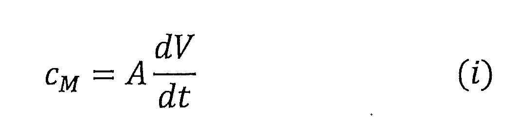
Priority Applications (2)
| Application Number | Priority Date | Filing Date | Title |
|---|---|---|---|
| CN202480033485.6A CN121152969A (zh) | 2023-05-19 | 2024-05-16 | 酶传感器 |
| EP24811014.0A EP4715378A1 (en) | 2023-05-19 | 2024-05-16 | Enzyme sensor |
Applications Claiming Priority (2)
| Application Number | Priority Date | Filing Date | Title |
|---|---|---|---|
| JP2023083361 | 2023-05-19 | ||
| JP2023-083361 | 2023-05-19 |
Publications (1)
| Publication Number | Publication Date |
|---|---|
| WO2024242007A1 true WO2024242007A1 (ja) | 2024-11-28 |
Family
ID=93589421
Family Applications (1)
| Application Number | Title | Priority Date | Filing Date |
|---|---|---|---|
| PCT/JP2024/018075 Ceased WO2024242007A1 (ja) | 2023-05-19 | 2024-05-16 | 酵素センサー |
Country Status (4)
| Country | Link |
|---|---|
| EP (1) | EP4715378A1 (ja) |
| JP (1) | JP2024167067A (ja) |
| CN (1) | CN121152969A (ja) |
| WO (1) | WO2024242007A1 (ja) |
Citations (11)
| Publication number | Priority date | Publication date | Assignee | Title |
|---|---|---|---|---|
| JPS62235557A (ja) * | 1986-04-05 | 1987-10-15 | Omron Tateisi Electronics Co | 酵素電極 |
| JPS62240849A (ja) * | 1986-04-11 | 1987-10-21 | Omron Tateisi Electronics Co | 酵素電極 |
| JPS6488244A (en) | 1987-09-30 | 1989-04-03 | Toshiba Corp | Measuring apparatus of fet enzyme sensor |
| JP2008128803A (ja) * | 2006-11-21 | 2008-06-05 | Hitachi Ltd | 電位差式センサ及び分析用素子 |
| JP2010054378A (ja) * | 2008-08-28 | 2010-03-11 | Tanita Corp | バイオセンサ、その製造方法、その使用方法 |
| JP2015079004A (ja) * | 2010-04-22 | 2015-04-23 | アークレイ株式会社 | バイオセンサ |
| JP2019132705A (ja) * | 2018-01-31 | 2019-08-08 | 旭化成株式会社 | 電気化学測定方法、電気化学測定装置、プログラムおよびコンピュータ可読記録媒体 |
| JP2019158650A (ja) | 2018-03-14 | 2019-09-19 | 国立大学法人山形大学 | トランジスタ型酵素センサ |
| JP2019203893A (ja) * | 2018-05-22 | 2019-11-28 | アークレイ株式会社 | 新規バイオセンシング法 |
| JP2021113821A (ja) * | 2016-08-29 | 2021-08-05 | 国立研究開発法人産業技術総合研究所 | グルコースセンサ用試薬、グルコースセンサ、グルコースセンサの製造方法、および、グルコース測定装置 |
| JP2023553889A (ja) | 2020-12-07 | 2023-12-26 | ザ ユニバーシティ オブ ノース カロライナ アット チャペル ヒル | バイオセンサーにおける測定方法 |
-
2024
- 2024-05-15 JP JP2024079566A patent/JP2024167067A/ja active Pending
- 2024-05-16 EP EP24811014.0A patent/EP4715378A1/en active Pending
- 2024-05-16 CN CN202480033485.6A patent/CN121152969A/zh active Pending
- 2024-05-16 WO PCT/JP2024/018075 patent/WO2024242007A1/ja not_active Ceased
Patent Citations (11)
| Publication number | Priority date | Publication date | Assignee | Title |
|---|---|---|---|---|
| JPS62235557A (ja) * | 1986-04-05 | 1987-10-15 | Omron Tateisi Electronics Co | 酵素電極 |
| JPS62240849A (ja) * | 1986-04-11 | 1987-10-21 | Omron Tateisi Electronics Co | 酵素電極 |
| JPS6488244A (en) | 1987-09-30 | 1989-04-03 | Toshiba Corp | Measuring apparatus of fet enzyme sensor |
| JP2008128803A (ja) * | 2006-11-21 | 2008-06-05 | Hitachi Ltd | 電位差式センサ及び分析用素子 |
| JP2010054378A (ja) * | 2008-08-28 | 2010-03-11 | Tanita Corp | バイオセンサ、その製造方法、その使用方法 |
| JP2015079004A (ja) * | 2010-04-22 | 2015-04-23 | アークレイ株式会社 | バイオセンサ |
| JP2021113821A (ja) * | 2016-08-29 | 2021-08-05 | 国立研究開発法人産業技術総合研究所 | グルコースセンサ用試薬、グルコースセンサ、グルコースセンサの製造方法、および、グルコース測定装置 |
| JP2019132705A (ja) * | 2018-01-31 | 2019-08-08 | 旭化成株式会社 | 電気化学測定方法、電気化学測定装置、プログラムおよびコンピュータ可読記録媒体 |
| JP2019158650A (ja) | 2018-03-14 | 2019-09-19 | 国立大学法人山形大学 | トランジスタ型酵素センサ |
| JP2019203893A (ja) * | 2018-05-22 | 2019-11-28 | アークレイ株式会社 | 新規バイオセンシング法 |
| JP2023553889A (ja) | 2020-12-07 | 2023-12-26 | ザ ユニバーシティ オブ ノース カロライナ アット チャペル ヒル | バイオセンサーにおける測定方法 |
Non-Patent Citations (1)
| Title |
|---|
| SONG, Y. ET AL.: "Design and preparation of open circuit potential biosensor for in vitro and in vivo glucose monitoring", ANAL BIOANAL CHEM, vol. 409, 2017, pages 161 - 168, XP036122925, DOI: doi.org/10.1007/ s 00216-016 -9982-1 * |
Also Published As
| Publication number | Publication date |
|---|---|
| EP4715378A1 (en) | 2026-03-25 |
| CN121152969A (zh) | 2025-12-16 |
| JP2024167067A (ja) | 2024-11-29 |
Similar Documents
| Publication | Publication Date | Title |
|---|---|---|
| Strakosas et al. | A non-enzymatic glucose sensor enabled by bioelectronic pH control | |
| JP7003103B2 (ja) | 干渉補償型の2電極テストストリップ | |
| Liu et al. | An AgNP-deposited commercial electrochemistry test strip as a platform for urea detection | |
| Cheng et al. | A mediator‐free electroenzymatic sensing methodology to mitigate ionic and electroactive interferents' effects for reliable wearable metabolite and nutrient monitoring | |
| Chaubey et al. | Mediated biosensors | |
| JP6435264B2 (ja) | 電気化学式バイオセンサを用いた物質の測定方法及び測定装置 | |
| US11608515B2 (en) | Biosensing method | |
| Huang et al. | A sensitive H2O2 biosensor based on carbon nanotubes/tetrathiafulvalene and its application in detecting NADH | |
| JP6817111B2 (ja) | 電気化学式バイオセンサを用いた物質の測定方法及び測定装置 | |
| EP3415634A1 (en) | Biosensor and measuring method using the same | |
| KR20060131836A (ko) | 바이오센서에 대한 내부 참조물질로서의 산화성 화학종 및이의 사용방법 | |
| EP3447483B1 (en) | Novel biosensing technology based on enzymatic electrochemical impedance measurement | |
| Fang et al. | An electrochemical biosensor of the ketone 3-β-hydroxybutyrate for potential diabetic patient management | |
| JP2021156877A (ja) | バイオセンサおよびそれを用いた測定方法 | |
| JP2024167067A (ja) | 酵素センサー | |
| US20150275389A1 (en) | A Method For Forming An Optical Test Sensor | |
| Hsu et al. | Fabrication of a glucose biosensor based on inserted barrel plating gold electrodes | |
| JP2025100045A (ja) | トランジスタ型酵素センサー | |
| US7794778B2 (en) | Amperometric sensor for uric acid and method for the same | |
| KR101109857B1 (ko) | 더블 펄스 방식을 이용한 바이오센서 | |
| JP2026047825A (ja) | 酵素センサー | |
| KR20220098525A (ko) | 바이오센서 | |
| TWI406940B (zh) | 矩陣列奈米生物感測器 | |
| min Lee | AMPEROMETRIC GLUCOSE BIOSENSORS: PAST, PRESENT AND FUTURE | |
| Gupta et al. | Molecular Nanomaterials Based Glucose Biosensor: An Overview |
Legal Events
| Date | Code | Title | Description |
|---|---|---|---|
| 121 | Ep: the epo has been informed by wipo that ep was designated in this application |
Ref document number: 24811014 Country of ref document: EP Kind code of ref document: A1 |
|
| WWE | Wipo information: entry into national phase |
Ref document number: 2024811014 Country of ref document: EP |
|
| NENP | Non-entry into the national phase |
Ref country code: DE |
|
| ENP | Entry into the national phase |
Ref document number: 2024811014 Country of ref document: EP Effective date: 20251219 |
|
| ENP | Entry into the national phase |
Ref document number: 2024811014 Country of ref document: EP Effective date: 20251219 |
|
| ENP | Entry into the national phase |
Ref document number: 2024811014 Country of ref document: EP Effective date: 20251219 |
|
| ENP | Entry into the national phase |
Ref document number: 2024811014 Country of ref document: EP Effective date: 20251219 |
|
| ENP | Entry into the national phase |
Ref document number: 2024811014 Country of ref document: EP Effective date: 20251219 |
|
| ENP | Entry into the national phase |
Ref document number: 2024811014 Country of ref document: EP Effective date: 20251219 |
|
| ENP | Entry into the national phase |
Ref document number: 2024811014 Country of ref document: EP Effective date: 20251219 |
|
| ENP | Entry into the national phase |
Ref document number: 2024811014 Country of ref document: EP Effective date: 20251219 |
|
| WWP | Wipo information: published in national office |
Ref document number: 2024811014 Country of ref document: EP |