WO2024241924A1 - 自動分析装置及びその分析方法 - Google Patents
自動分析装置及びその分析方法 Download PDFInfo
- Publication number
- WO2024241924A1 WO2024241924A1 PCT/JP2024/017503 JP2024017503W WO2024241924A1 WO 2024241924 A1 WO2024241924 A1 WO 2024241924A1 JP 2024017503 W JP2024017503 W JP 2024017503W WO 2024241924 A1 WO2024241924 A1 WO 2024241924A1
- Authority
- WO
- WIPO (PCT)
- Prior art keywords
- sample
- specimen
- predetermined amount
- dispensing
- dispensing unit
- Prior art date
- Legal status (The legal status is an assumption and is not a legal conclusion. Google has not performed a legal analysis and makes no representation as to the accuracy of the status listed.)
- Ceased
Links
Images









Classifications
-
- G—PHYSICS
- G01—MEASURING; TESTING
- G01N—INVESTIGATING OR ANALYSING MATERIALS BY DETERMINING THEIR CHEMICAL OR PHYSICAL PROPERTIES
- G01N35/00—Automatic analysis not limited to methods or materials provided for in any single one of groups G01N1/00 - G01N33/00; Handling materials therefor
- G01N35/10—Devices for transferring samples or any liquids to, in, or from, the analysis apparatus, e.g. suction devices, injection devices
- G01N35/1004—Cleaning sample transfer devices
-
- G—PHYSICS
- G01—MEASURING; TESTING
- G01N—INVESTIGATING OR ANALYSING MATERIALS BY DETERMINING THEIR CHEMICAL OR PHYSICAL PROPERTIES
- G01N35/00—Automatic analysis not limited to methods or materials provided for in any single one of groups G01N1/00 - G01N33/00; Handling materials therefor
- G01N35/10—Devices for transferring samples or any liquids to, in, or from, the analysis apparatus, e.g. suction devices, injection devices
- G01N35/1002—Reagent dispensers
-
- G—PHYSICS
- G01—MEASURING; TESTING
- G01N—INVESTIGATING OR ANALYSING MATERIALS BY DETERMINING THEIR CHEMICAL OR PHYSICAL PROPERTIES
- G01N35/00—Automatic analysis not limited to methods or materials provided for in any single one of groups G01N1/00 - G01N33/00; Handling materials therefor
- G01N35/10—Devices for transferring samples or any liquids to, in, or from, the analysis apparatus, e.g. suction devices, injection devices
- G01N35/1009—Characterised by arrangements for controlling the aspiration or dispense of liquids
- G01N35/1016—Control of the volume dispensed or introduced
-
- G—PHYSICS
- G01—MEASURING; TESTING
- G01N—INVESTIGATING OR ANALYSING MATERIALS BY DETERMINING THEIR CHEMICAL OR PHYSICAL PROPERTIES
- G01N35/00—Automatic analysis not limited to methods or materials provided for in any single one of groups G01N1/00 - G01N33/00; Handling materials therefor
- G01N35/10—Devices for transferring samples or any liquids to, in, or from, the analysis apparatus, e.g. suction devices, injection devices
- G01N35/1009—Characterised by arrangements for controlling the aspiration or dispense of liquids
- G01N35/1016—Control of the volume dispensed or introduced
- G01N2035/1018—Detecting inhomogeneities, e.g. foam, bubbles, clots
-
- G—PHYSICS
- G01—MEASURING; TESTING
- G01N—INVESTIGATING OR ANALYSING MATERIALS BY DETERMINING THEIR CHEMICAL OR PHYSICAL PROPERTIES
- G01N35/00—Automatic analysis not limited to methods or materials provided for in any single one of groups G01N1/00 - G01N33/00; Handling materials therefor
- G01N35/10—Devices for transferring samples or any liquids to, in, or from, the analysis apparatus, e.g. suction devices, injection devices
- G01N2035/1027—General features of the devices
- G01N2035/103—General features of the devices using disposable tips
Definitions
- the present invention relates to an automatic analyzer.
- the present invention aims to provide an automatic analyzer that can accurately detect abnormalities during aspiration even when the amount of sample used for analysis is small.
- the automatic analyzer of the present invention includes a dispensing unit that aspirates a specimen from a specimen container that contains the specimen, a control unit that controls the dispensing unit to aspirate a third predetermined amount of the specimen, which is greater than a first predetermined amount that is the amount of the specimen used in the analysis, and then discharge a second predetermined amount of the specimen to a predetermined location other than the specimen container, and then discharge the first predetermined amount of the specimen into a reaction container used in the analysis, a detection unit that detects the pressure waveform in the dispensing unit, and a determination unit that determines whether the dispensing unit has insufficiently aspirated the specimen (empty aspiration), and/or whether the specimen is clogged in the dispensing unit, based on a first waveform, which is the pressure waveform when the dispensing unit aspirates the specimen.
- the present invention makes it possible to provide an automatic analyzer that can accurately detect abnormalities during suction even when the amount of sample used for analysis is small.
- FIG. 1 is a schematic diagram showing the overall configuration of an automatic analyzer.
- FIG. 1 is a schematic diagram showing the configuration of a portion of an automatic analyzer (particularly, a portion related to sample dispensing).
- 11 is a flowchart showing the first half of a method for determining an abnormality during dispensing.
- 11 is a flowchart showing the second half of the method for determining an abnormality during dispensing.
- 11 is a flowchart showing a method for determining whether or not the nozzle is empty.
- 13A and 13B are diagrams showing examples of a first waveform during normal aspiration and a first waveform during dry aspiration for a sample that is a second predetermined amount larger than a first predetermined amount.
- FIG. 1 is a schematic diagram showing the overall configuration of an automatic analyzer.
- FIG. 1 is a schematic diagram showing the configuration of a portion of an automatic analyzer (particularly, a portion related to sample dispensing).
- 11 is a flowchart showing the
- FIG. 13 is a diagram showing an example of a second waveform for determining dry suction.
- FIG. 13 is a diagram showing an example in which a first threshold value (a threshold value for determining whether or not the device is empty) can be set.
- FIG. 13 is a diagram showing an example in which the first threshold value (threshold value for determining whether or not the device is empty) cannot be set.
- 13A and 13B are diagrams showing examples of a first waveform when a sample that is a second predetermined amount larger than a first predetermined amount is normally aspirated, and a first waveform when the first predetermined amount of sample is normally aspirated.
- FIG. 13 is a diagram showing an example of a setting tolerance of a first threshold value (a threshold value for determining whether or not the first threshold value is empty); 11 is a flowchart showing a method for determining whether a blockage has occurred.
- 5A and 5B are diagrams showing examples of pressure waveforms (first waveform and second waveform for determining clogging) during normal suction and when clogging occurs.
- FIG. 13 is a diagram showing an example in which a second threshold value (a threshold value for determining clogging) can be set.
- FIG. 13 is a diagram showing an example in which the second threshold value (threshold value for determining clogging) cannot be set.
- FIG. 13A and 13B are diagrams showing examples of pressure waveforms when a clogged sample that is a second predetermined amount larger than a first predetermined amount is aspirated, and examples of pressure waveforms when a clogged sample of the first predetermined amount is aspirated.
- FIG. 13 is a diagram showing an example of a setting tolerance of a second threshold value (a threshold value for determining clogging).
- Fig. 1 is a schematic diagram showing the overall configuration of an automatic analyzer.
- the automatic analyzer is composed of a reaction vessel tray 20, a dispensing tip/reaction vessel transport mechanism 17, a reaction disk 1, a reagent/sample common storage section 3, a first dispensing mechanism 8, a second dispensing mechanism 9, a dispensing tip tray 19, a spectrophotometer 15, a detection mechanism 16, a dispensing tip/reaction vessel disposal box 21, water supply pumps 10 and 11, washing tanks 12 and 13, a control section 28, and the like.
- the reaction vessel tray 20 stores the reaction vessels 2.
- the dispensing tip/reaction vessel transport mechanism 17 supplies the reaction vessels 2 from the reaction vessel tray 20 to the reaction disk 1.
- the reaction disk 1 has multiple reaction vessels 2 placed in the circumferential direction and is rotated to move the reaction vessels 2 to predetermined positions.
- the reagent/specimen common storage section 3 has multiple reagent containers and specimen containers placed in it. Note that in FIG. 1, the reagent containers 4 are located on the inner periphery of the specimen containers 5, but the specimen containers 5 may be located on the inner periphery of the reagent containers 4, or the reagent containers 4 and specimen containers 5 may be configured to be separated in the circumferential direction rather than the radial direction.
- the first dispensing mechanism 8 and the second dispensing mechanism 9 are installed between the reaction disk 1 and the common reagent/specimen storage section 3, and aspirate specimens from specimen containers 5 and dispense them into reaction containers 2, and aspirate reagents from reagent containers 4 and dispense them into reaction containers 2.
- the first dispensing mechanism 8 and the second dispensing mechanism 9 are used for different analytical tests. For example, if the first dispensing mechanism 8 is for biochemistry and the second dispensing mechanism 9 is for immunology, the first dispensing mechanism 8 dispenses specimens and reagents for biochemistry tests, and the second dispensing mechanism 9 dispenses specimens and reagents for immunology tests.
- the first dispensing mechanism 8 accesses and dispenses them for biochemistry tests
- the second dispensing mechanism 9 accesses and dispenses them for immunology tests.
- a dispensing tip 18 is attached to the dispensing probe 102 (see Figure 2) of the second dispensing mechanism 9 during dispensing.
- the dispensing tip tray 19 stores the dispensing tips 18.
- the dispensing tip/reaction vessel transport mechanism 17 supplies the dispensing tips 18 to the dispensing tip mounting position 22, where the dispensing tips 18 are mounted on the dispensing probe 102.
- the dispensing probe 102 is capable of rotational and vertical movement.
- the rotational trajectory of the dispensing probe 102 includes a reagent suction position 6 and a sample suction position 7 on the common reagent/sample storage section 3, a first dispensing position and a second dispensing position on the reaction disk 1, and a washing tank 12 (13) for washing the dispensing probe 102. Since the second dispensing mechanism 9 uses a dispensing tip 18, the rotational trajectory of the dispensing probe 102 also includes a dispensing tip attachment position 22 and a dispensing tip disposal position 23.
- the sample and reagent are aspirated by the dispensing probe 102, and in immunological testing, the sample and reagent are aspirated by the dispensing tip 18 attached to the dispensing probe 102.
- the sample and reagent are stirred and mixed in the reaction vessel 2 by the aspirating and dispensing action of the dispensing probe 102 or the dispensing tip 18.
- the sample and the reagent are mixed by a pipetting operation using the dispensing probe 102 or the dispensing tip 18, but a mixing mechanism for mixing the sample and the reagent may be provided.
- the reaction vessel 2 containing the reaction liquid in which the sample and the reagent are mixed is controlled at a predetermined temperature by the reaction disk 1, and the reaction is promoted for a predetermined time.
- the spectrophotometer 15 for biochemical testing is installed around the reaction disk 1 and is equipped with a light source and a detector (not shown). It measures the absorbance of the reaction solution by irradiating the reaction solution, which is a mixture of a sample and a reagent, with a light source and detecting the transmitted light obtained by dispersing the light.
- the detection mechanism 16 for immunoassays uses a photomultiplier tube as a detector to measure the amount of luminescence resulting from the luminescence reaction of the labeling substance contained in the reaction solution that has been reacted for a specified time by the reaction disk 1.
- the reaction vessel 2 for which absorbance measurement has been completed on the reaction disk 1 is disposed of in the dispensing tip/reaction vessel disposal box 21 by the dispensing tip/reaction vessel transport mechanism 17.
- the reaction vessel 2 containing the reaction liquid that has been reacted for a predetermined time by the reaction disk 1 is moved to the detection mechanism 16, and the reaction vessel 2 for which measurement has been completed by the detection mechanism 16 is also moved to the dispensing tip/reaction vessel disposal box 21 by the dispensing tip/reaction vessel transport mechanism 17.
- Water supply pumps 10 and 11 are connected to the first dispensing mechanism 8 and the second dispensing mechanism 9, respectively, and supply washing water for washing the inside of the dispensing probe 102 (internal washing) and for washing the outside of the dispensing tip 18 (external washing).
- the washing tank 12 performs internal or external washing of the first dispensing mechanism 8, and the washing tank 13 performs internal or external washing of the second dispensing mechanism 9.
- the control unit 28 is connected to each mechanism of the automatic analyzer, and controls, for example, the rotational drive of the reaction disk 1, the rotational drive and vertical drive of the dispensing probe 102, and the aspirating and dispensing operations of the sample and reagent. Note that in FIG. 1, for the sake of simplicity, the connections between each mechanism constituting the automatic analyzer and the control unit 28 are omitted.
- the control unit 28 also performs calculations for specified analysis items based on the measured values from the spectrophotometer 15 or the detection mechanism 16, and displays the test results on the display unit 126 (see FIG. 2).
- FIG. 2 is a schematic diagram showing the configuration of a part of the automatic analyzer (particularly the part related to sample dispensing).
- the dispensing mechanism (second dispensing mechanism 9) is mainly composed of a dispensing probe 102, a flow path 103, a syringe 104, a syringe driving unit 106, a probe driving unit 107, a dispensing control unit 108, a detection unit 117, a branching block 118, a determination unit 121, etc.
- the dispensing probe 102 is connected to a syringe 104 via a flow path 103, and the inside of these is filled with cleaning water 105.
- the syringe 104 has a cylinder 104a and a plunger 104b, and a syringe drive unit 106 is connected to the plunger 104b.
- the syringe drive unit 106 drives the plunger 104b in the vertical direction relative to the cylinder 104a, thereby aspirating and discharging fluids (liquid and gas) in the dispensing tip 18 connected to the dispensing probe 102.
- the syringe 104 has a flow path that communicates with the water supply tank 110, and this flow path is provided with an internal washing solenoid valve 111 and a water supply pump 11.
- the water supply tank 110 contains washing water 105, and the water supply pump 11 is driven to discharge the washing water 105 from the dispensing probe 102, thereby washing the inside of the dispensing probe 102.
- the external washing nozzle 123 also has a flow path that communicates with the water supply tank 110, and this flow path is provided with an external washing solenoid valve 125 and a water supply pump 11. Therefore, the water supply pump 11 is driven to discharge the washing water 105 from the external washing nozzle 123 toward the dispensing tip 18, thereby washing the outside of the dispensing tip 18.
- the dispensing probe 102 is washed in the washing tank 13, for example, before dispensing the reagent 113 and the specimen 115, and the dispensing tip 18 is washed in the washing tank 13, for example, after dispensing the reagent 113 and the specimen 115.
- the dispensing control unit 108 controls the operation of the syringe driving unit 106, the probe driving unit 107, the water supply pump 11, the internal washing solenoid valve 111, and the external washing solenoid valve 125.
- the dispensing control unit 108 may be configured to control not only each component of the dispensing mechanism, but also the operation of the entire automatic analyzer, in which case the functions of the dispensing control unit 108 are performed by the control unit 28.
- the detection unit 117 is, for example, a pressure sensor, which is connected to a branch block 118 provided midway through the flow path 103 and measures the pressure within the flow path 103.
- the determination unit 121 is a circuit for determining whether or not there is an abnormality during the dispensing operation of the dispensing mechanism, and has a memory unit 119 that stores data such as pressure values, and a calculation unit 120 that executes processing related to the data stored in the memory unit 119.
- the determination unit 121 is also configured to be able to communicate with the dispensing control unit 108, and when it is determined from the results of data processing in the calculation unit 120 that an operation needs to be stopped, it transmits the details of the operation to the dispensing control unit 108.
- the determination unit 121 may be incorporated within the dispensing control unit 108.
- the display unit 126 is connected to the dispensing control unit 108 and the judgment unit 121, and displays the presence or absence of abnormalities, which are the results of data processing in the judgment unit 121.
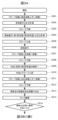
- FIGS. 3A and 3B are flow charts showing a method for determining an abnormality during dispensing
- Fig. 3B is a continuation of Fig. 3A.
- the dispensing control unit 108 shown in Fig. 2 controls the operation of each component of the dispensing mechanism (such as the syringe driving unit 106, the probe driving unit 107, the water supply pump 11, the internal washing solenoid valve 111, and the external washing solenoid valve 125), but in the following, each component of the dispensing mechanism may be described as the subject of the operation.
- step S301 the probe driver 107 moves the dispensing probe 102 with the dispensing tip 18 attached to it above the sample container 5.
- step S302 the syringe driving unit 106 drives the syringe 104 to aspirate air.
- the detection unit 117 detects the pressure waveform in the flow path 103 within a predetermined time range that includes the time during which the syringe 104 is aspirating air, and the detection result is stored in the memory unit 119 as a second waveform for determining dry aspiration.
- the "pressure waveform” refers to data in which pressure values are arranged in chronological order.
- step S303 the probe driver 107 lowers the dispensing probe 102 until the tip of the dispensing tip 18 is immersed in the sample 115.
- step S304 the detection unit 117 detects the pressure waveform in the flow path 103 during a predetermined time range while the syringe 104 is stopped before aspirating the sample 115, and the detection result is stored in the memory unit 119 as a second waveform for determining clogging.
- the syringe drive unit 106 then drives the syringe 104 to aspirate a third predetermined amount of the sample 115, which is a second predetermined amount more than the first predetermined amount, which is the amount of sample used in the analysis, into the dispensing tip 18.
- the detection unit 117 detects the pressure waveform in the flow path 103 during a predetermined time range during the aspirating operation of the sample 115, and the result is stored in the memory unit 119 as a first waveform.
- step S305 the probe driver 107 raises the dispensing probe 102 to separate the tip of the dispensing tip 18 from the liquid surface of the sample 115.
- step S306 the syringe drive unit 106 drives the syringe 104 to aspirate air.
- step S307 the probe driver 107 moves the dispensing probe 102 above the washing tank 13.
- step S308 the probe driver 107 lowers the dispensing probe 102 to a position where the tip of the dispensing tip 18 contacts the cleaning water.
- step S309 the syringe drive unit 106 drives the syringe 104 to eject the second predetermined amount of specimen 115 together with air into the washing tank 13.
- the ejection position of the second predetermined amount of specimen 115 may be a container that contains the liquid, a container that discards the liquid, or the reaction vessel 2, but it is more efficient to eject the second predetermined amount of specimen 115 into the washing tank 13 where the dispensing probe 102 stops for external washing.
- the ejection timing of the second predetermined amount of specimen 115 is not limited to step S309, and may be any time between steps S308 and S310.
- step S310 the dispensing control unit 108 opens the external washing solenoid valve 125, drives the water supply pump 11, and ejects the washing water 105 from the external washing nozzle 123 to wash the outside of the dispensing tip 18 attached to the dispensing probe 102.
- the probe driving unit 107 raises the dispensing probe 102.
- step 311 the probe driver 107 moves the dispensing probe 102 above the reaction vessel 2.
- step S312 the probe driver 107 lowers the dispensing probe 102 to the discharge position into the reaction vessel 2.
- the syringe driving unit 106 drives the syringe 104 to eject the first predetermined amount of the specimen 115 and the reagent 113 held inside the dispensing tip 18.
- the third predetermined amount which is the amount of specimen 115 aspirated in step S304, is assumed to be only the sum of the first and second predetermined amounts, but it may be these amounts plus a fourth predetermined amount. In this case, the fourth predetermined amount remains inside the dispensing tip 18 or the dispensing probe 102 even after step S213, and is ejected in the washing tank 13, etc.
- step S314 the probe driver 107 moves the dispensing probe 102 to the dispensing tip disposal position 23, removes the dispensing tip 18 from the dispensing probe 102, and discards it in the dispensing tip/reaction vessel disposal box 21.
- step S315 the calculation unit 120 of the determination unit 121 determines whether or not there was an abnormality, such as empty suction, in which the dispensing mechanism was not sufficiently suctioning the sample, or clogging, in which the dispensing mechanism was clogged with the sample, during the aspiration of the sample 115, based on the pressure waveform during the aspiration of the sample stored in the memory unit 119.
- an abnormality such as empty suction
- clogging in which the dispensing mechanism was clogged with the sample
- step S315 the determination unit 121 transmits the determination result of the presence or absence of an abnormality to the display unit 126 and the dispensing control unit 108, and the display unit 126 displays the received determination result.
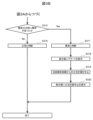
- step S315 If it is determined in step S315 that the operation is normal (no abnormality) (No), the process proceeds to step S316.
- step S316 the dispensing control unit 108 determines that dispensing has ended normally based on the determination result received from the determination unit 121, and ends the dispensing operation.
- step S315 determines that an abnormality exists (Yes)
- the process proceeds to step S317.
- step S317 the dispensing control unit 108 determines that an abnormality occurred during the aspirating of the sample 115 based on the determination result received from the determination unit 121, and then proceeds to step S318.
- step S318 the dispensing control unit 108 displays an alert on the display unit 126, and then proceeds to step S319.
- step S319 the dispensing control unit 108 ends the dispensing operation of the sample 115 determined in step S317 to have an abnormality during dispensing, and thereafter cancels the dispensing plan for the sample 115 from that sample container 5. In this way, by canceling the dispensing plan for the sample 115 that had an abnormality, it is possible to reduce the consumption of reagents used in subsequent analyses.
- step S320 the dispensing control unit 108 displays on the display unit 126 that the dispensing plan for the sample 115 has been canceled.
- steps S301 to S320 are repeated.
- the abnormality determination process in steps S315 to S320 may be performed before the process in steps S305 to S314, or may be performed in parallel with the process in steps S305 to S314.
- the dispensing control unit 108 executes steps S305 and S306 and then ends the dispensing operation without proceeding to step S307. This avoids the need to eject the abnormal sample 115 into the reaction vessel 2, thereby reducing the consumption or effort required for cleaning the reaction vessel 2.
- step S315 in FIG. 3A There are two main abnormalities to be determined: empty aspiration and clogging during sample aspiration, and these will be explained using Example 1 and Example 2.
- the calculation unit 120 of the determination unit 121 calculates a determination index based on the pressure waveform during sample aspiration, and determines the presence or absence of an abnormality during sample aspiration based on the determination index.
- the “determination index” may be, for example, the average pressure value during the aspirating operation of the specimen 115, the sum or average of the pressure values before or after the aspirating operation of the specimen 115, the maximum or minimum pressure value, the pulsation period or amplitude of the pressure waveform, the statistical distance (such as Euclidean distance) between a preset reference pressure waveform and the pressure waveform acquired in this step.
- the "reference pressure waveform" is, for example, a waveform set using a large number of pressure values acquired in the past, and the pressure value when it is determined that the specimen has been aspirated normally may be used, or the pressure value when it is determined that an abnormality has occurred during the aspirating of the specimen may be used.
- the similarity or dissimilarity with this reference pressure waveform may also be used as the determination index.
- a combination of multiple such determination indexes may be used as the determination index.
- Figure 4 is a flowchart showing the method of determining whether the pump is dry, which is one of the abnormality determination methods in step S315 of Figure 3A.
- step S401 the calculation unit 120 reads out the first waveform and the second waveform for determining dry suction stored in the memory unit 119.
- step S402 the calculation unit 120 calculates a first judgment index used to judge whether or not dry suction exists, based on the first waveform and the second waveform for determining dry suction.
- the difference between the average value in a predetermined section of the first waveform detected in step S304 and the average value in a predetermined section of the second waveform for determining dry suction detected in step S302 (the value obtained by subtracting the average value of the latter from the average value of the former) is used as the first judgment index.
- the first judgment index may be calculated using a method other than the above.
- the calculation unit 120 determines whether or not dry aspiration occurred when the sample 115 was aspirated based on the first determination index.
- Methods for determining whether or not dry aspiration occurred include, for example, a method of comparing the first determination index with a predetermined threshold value, and a method of determining that an abnormality exists when a combination of multiple first determination indexes satisfies a certain condition.
- the former method i.e., the method of comparing the first determination index with a predetermined threshold value, is used to determine whether or not dry aspiration abnormality exists.
- FIG. 5A shows an example of a first waveform during normal aspiration and a first waveform during dry aspiration for a sample that is a second predetermined amount greater than the first predetermined amount.
- the first waveform 502 during dry aspiration is shifted in the positive direction of the pressure axis. Therefore, the first judgment index during normal aspiration is a smaller value than the first judgment index during dry aspiration.
- FIG. 5B shows an example of the second waveform for determining whether or not there is dry suction.
- the second waveform for determining whether or not there is dry suction 503 is acquired in step S302, and therefore is not affected by whether or not there is dry suction or normal suction.
- the first determination index during dry suction is A
- the first determination index during normal suction is B
- the average of the first determination index A is A-
- the average of the first determination index B is B-
- the threshold value for dry suction determination is a constant k1.
- the lower limit of the values assumed for the first determination index A is assumed to be the assumed lower limit value C for dry suction.
- the assumed lower limit value C for dry suction may be set to the lower limit value of the distribution of previously acquired data during dry suction, but if an error is acceptable, a lower limit value that includes a certain amount or more of the data during dry suction may be set.
- the upper limit of the values assumed for the first determination index B is assumed to be the assumed upper limit value D for normal suction.
- the assumed upper limit value D for normal suction may be set to the upper limit value of the distribution of previously acquired data during normal suction, but if an error is acceptable, a upper limit value that includes a certain amount or more of the data during normal suction may be set.
- variable x may be, for example, the amount of dispensing, the temperature, or the xth dispensing in the case of continuous dispensing operations, or may be a calibration value calculated for each device to eliminate differences between devices.
- the variable x is not limited to one and may be multiple.
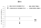
- Fig. 6A is a diagram showing an example in which a first threshold value (threshold value for determining dry suction) can be set.
- a first threshold value threshold value for determining dry suction
- a constant k1 can be set between C and D as the first threshold value, so that dry suction and normal suction can be determined with high accuracy.
- the first determination index is larger than the first threshold value, dry suction can be determined, and when the first determination index is smaller than the first threshold value, normal suction can be determined.
- the setting method of the first threshold and the method of judging dry suction are also different.
- a first judgment index is used that has a larger value during normal suction than during dry suction
- the assumed upper limit during dry suction is C' and the assumed lower limit during normal suction is D'
- the first threshold can be set between C' and D'.
- the first judgment index is smaller than the first threshold, it can be judged as dry suction
- the first judgment index is larger than the first threshold, it can be judged as normal suction.
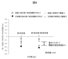
- FIG. 6B is a diagram showing an example of a case where the first threshold value (threshold value for determining whether or not the ink is empty) cannot be set.
- the first threshold value threshold value for determining whether or not the ink is empty
- FIG. 6B when A - > B - and C ⁇ D, it becomes difficult to distinguish between dry suction and normal suction because the first threshold cannot be set between C and D.
- a first judgment index is used that has a larger value during normal suction than during dry suction
- a - ⁇ B - and C'>D' it becomes difficult to distinguish between dry suction and normal suction because the first threshold cannot be set between C' and D'.
- the first waveform 702 when the first predetermined amount is aspirated ends up finishing the aspiration earlier than the first waveform 701 when the amount that is a second predetermined amount greater than the first predetermined amount is aspirated. Therefore, in addition to the pressure waveform that reflects the characteristics during the aspiration operation, the pressure waveform that reflects the characteristics after the aspiration ends is included in the calculation section of the pressure value.
- the pressure value calculated from the first waveform 702 is greater than the pressure value calculated from the first waveform 701. Furthermore, since the pressure waveform after the aspiration ends varies greatly, if the pressure waveform after the aspiration ends is included, the first judgment index varies more and the judgment accuracy decreases.
- FIG. 8 shows an example of the setting tolerance of the first threshold (threshold for determining whether the cartridge is empty).
- the setting tolerance m1 itself does not exist, and the indicator region during dry aspiration and the indicator region during normal aspiration partially overlap.
- the second state which is not shown, A- > B- and C>D, the setting tolerance m1 exists but is smaller than a predetermined value, the indicator region during dry aspiration and the indicator region during normal aspiration are close, and there is a possibility of erroneous determination depending on the variation in the first determination indicator.
- the determination accuracy decreases compared to when the amount of the sample 115 equal to the sum of the first and second predetermined amounts is aspirated. Furthermore, even when the first judgment index is used, which has a larger value during normal suction than during dry suction, the result will be either A- ⁇ B- and C'>D', or A- ⁇ B- and C' ⁇ D' but the difference between C' and D' is smaller than a specified value, and the judgment accuracy will similarly decrease.
- a second predetermined amount of sample is aspirated, which is the amount of sample used in the analysis, to determine whether the aspirate is dry or normal.
- This allows for highly accurate determination even when the first predetermined amount is small, without modifying the device by using a highly sensitive pressure sensor or making the tip thinner.
- this embodiment does not require setting a calculation range for each first predetermined amount, or changing the threshold for each first predetermined amount. In other words, this embodiment has the advantage that the calculation method and threshold for the first determination index can be standardized regardless of the amount of sample used in the analysis.
- Figure 9 is a flowchart showing a method for determining whether a blockage has occurred, which is one of the abnormality determination methods in step S315 of Figure 3A.
- step S901 the calculation unit 120 reads out the first waveform and the second waveform for determining clogging stored in the memory unit 119.
- the calculation unit 120 calculates a second judgment index used to judge the presence or absence of a clogging based on the first waveform and the second waveform for clogging judgment.
- the second judgment index is the difference between the integrated value in a predetermined section of the first waveform detected in step S304 and the value obtained by multiplying the average value of the second waveform for clogging judgment detected in step S304 by the number of data points in the integrated range of the first waveform (the value obtained by subtracting the former from the latter).
- the second judgment index may be calculated by a method other than the above.
- step S903 the calculation unit 120 determines whether or not a clog has occurred when the sample 115 is aspirated based on the second determination index.
- Methods for determining whether or not a clog has occurred include, for example, a method of comparing the second determination index with a predetermined threshold value, and a method of determining that an abnormality exists when a combination of multiple second determination indexes satisfies a certain condition.
- the former method i.e., the method of comparing the second determination index with a predetermined threshold value, is used to determine whether or not a clog abnormality has occurred.
- FIG. 10 shows examples of pressure waveforms (first waveform and second waveform for determining clogging) during normal aspiration and when there is clogging.
- first waveform and second waveform for determining clogging are pressure waveforms during normal aspiration and when there is clogging.
- the first waveform drifts in the negative direction of the pressure axis. Therefore, the second determination index during normal aspiration is a smaller value than the second determination index during clogging.
- the second waveform for determining clogging is acquired before the sample 115 is aspiration, and therefore is not affected by clogging or normal aspiration.
- the second determination index during clogging is E
- the second determination index during normal suction is F
- the average of the second determination index E is E-
- the average of the second determination index F is F-
- the threshold value for determining clogging is a constant k2.
- the lower limit of the values assumed for the second determination index E is assumed to be a clogging assumed lower limit value G.
- the clogging assumed lower limit value G may be set to the lower limit of the distribution of clogging data acquired in the past, but if an error is acceptable, a lower limit value that includes a certain amount of clogging data or more may be set.
- the upper limit of the values assumed for the second determination index F is assumed to be a normal suction assumed upper limit value H.
- the normal suction assumed upper limit value H may be set to the upper limit of the distribution of normal suction data acquired in the past, but if an error is acceptable, a upper limit value that includes a certain amount of normal suction data or more may be set.
- variable x may be, for example, the amount of dispensing, the temperature, or the xth dispensing in the case of successive dispensing operations, or may be a calibration value calculated for each device to eliminate differences between devices.
- the variable x is not limited to one and may be multiple.
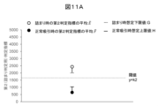
- FIG. 11A is a diagram showing an example in which a second threshold value (a threshold value for determining clogging) can be set.
- a second threshold value a threshold value for determining clogging
- 11A when E->F- and G>H, a constant k2 can be set as the second threshold between G and H, making it possible to accurately determine whether a clog exists or normal suction. Specifically, when the second judgment index is greater than the second threshold, a clog exists, and when the second judgment index is less than the second threshold, a normal suction exists.
- the method of setting the second threshold and the method of judging a clog will also be different. For example, if a second judgment index is used that is greater during normal suction than during a clog, and the assumed upper limit during a clog is G' and the assumed lower limit during normal suction is H', then when E- ⁇ F- and G' ⁇ H', the second threshold can be set between G' and H'. In this case, if the second judgment index is smaller than the second threshold, it can be judged as a clog, and if the second judgment index is greater than the second threshold, it can be judged as normal suction.
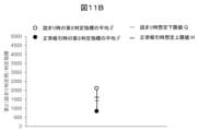
- FIG. 11B is a diagram showing an example of a case where the second threshold (threshold for determining clogging) cannot be set.
- the second threshold when E->F- and G ⁇ H, the second threshold cannot be set between G and H, making it difficult to determine whether a clogging occurs or normal suction.
- a second determination index is used that has a larger value during normal suction than during clogging, when E- ⁇ F- and G'>H', the first threshold cannot be set between G' and H', making it difficult to determine whether a clogging occurs or normal suction.
- FIG. 12 shows an example of a pressure waveform when a clogged sample that is a second predetermined amount greater than the first predetermined amount is aspirated, and a pressure waveform when a clogged sample of the first predetermined amount is aspirated.
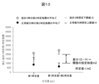
- FIG. 13 shows an example of the setting tolerance of the second threshold (threshold for determining clogging).
- the setting tolerance m2 itself does not exist, and the indicator region during clogging and the indicator region during normal aspirating partially overlap.
- the setting tolerance m2 exists but is smaller than a predetermined value, the indicator region during clogging and the indicator region during normal aspirating are close, and there is a possibility of erroneous judgment depending on the variation in the second judgment indicator.
- the judgment accuracy decreases compared to when the amount of sample 115 equal to the sum of the first and second predetermined amounts is aspirated. Furthermore, even if a second judgment index is used, in which the value during normal suction is greater than the value during clogging, the result will be either E- ⁇ F- and G'>H', or E- ⁇ F- and G' ⁇ H', but the difference between G' and H' is smaller than a predetermined value, and the judgment accuracy will similarly decrease.
- a second predetermined amount of sample is aspirated, which is the amount of sample used in the analysis, to determine whether there is a blockage or normal aspirated.
- This allows for highly accurate determination even when the first predetermined amount is small, without modifying the device by using a highly sensitive pressure sensor or making the tip thinner.
- this embodiment does not require setting a calculation range for each first predetermined amount, or changing the threshold for each first predetermined amount. In other words, this embodiment has the advantage that the calculation method and threshold for the second determination index can be standardized regardless of the amount of sample used in the analysis.
- first and second embodiments as examples, but it is also possible to replace part of the configuration of one embodiment with the configuration of another embodiment, and it is also possible to add the configuration of one embodiment to the configuration of another embodiment. Furthermore, the present invention is not limited to each embodiment, and various modified examples are included.
- the determination index is calculated based on the difference between the second waveform and the first waveform, but a certain degree of accuracy can be obtained even if the determination index is calculated based only on the first waveform.
- the analysis request items include a first analysis item in which the first predetermined amount is smaller than the second threshold value, and a second analysis item in which the first predetermined amount is larger than the second threshold value
- the dispensing unit may be controlled as in each embodiment for the first analysis item, and the dispensing unit may be controlled to aspirate and dispense only the first predetermined amount of sample for the second analysis item.
- reaction disk 2... reaction vessel, 3... common reagent/sample storage section, 4... reagent vessel, 5... sample vessel, 6... reagent suction position, 7... sample suction position, 8... first dispensing mechanism, 9... second dispensing mechanism, 10, 11... water supply pump, 12, 13... washing tank, 15... spectrophotometer, 16... detection mechanism, 17... dispensing tip/reaction vessel transport mechanism, 18... dispensing tip, 19... dispensing tip tray, 20... reaction vessel tray, 21... dispensing tip/reaction vessel disposal box, 22... dispensing tip mounting position, 23...
- dispensing tip tip disposal position 28...controller, 102...dispensing probe, 103...flow path, 104...syringe, 104a...cylinder, 104b...plunger, 105...washing water, 106...syringe drive unit, 107...probe drive unit, 108...dispensing control unit, 110...water supply tank, 111...internal washing solenoid valve, 113...reagent, 115...sample, 117...detection unit, 118...branch block, 119...storage unit, 120...calculation unit, 121...determination unit, 123...external washing nozzle, 125...external washing solenoid valve, 126...display unit.
Landscapes
- Physics & Mathematics (AREA)
- Health & Medical Sciences (AREA)
- Life Sciences & Earth Sciences (AREA)
- Chemical & Material Sciences (AREA)
- Analytical Chemistry (AREA)
- Biochemistry (AREA)
- General Health & Medical Sciences (AREA)
- General Physics & Mathematics (AREA)
- Immunology (AREA)
- Pathology (AREA)
- Automatic Analysis And Handling Materials Therefor (AREA)
Priority Applications (3)
| Application Number | Priority Date | Filing Date | Title |
|---|---|---|---|
| JP2025522312A JPWO2024241924A1 (https=) | 2023-05-22 | 2024-05-10 | |
| EP24810932.4A EP4718077A1 (en) | 2023-05-22 | 2024-05-10 | Automated analysis device and analysis method therefor |
| CN202480010249.2A CN120569632A (zh) | 2023-05-22 | 2024-05-10 | 自动分析装置及其分析方法 |
Applications Claiming Priority (2)
| Application Number | Priority Date | Filing Date | Title |
|---|---|---|---|
| JP2023083671 | 2023-05-22 | ||
| JP2023-083671 | 2023-05-22 |
Publications (1)
| Publication Number | Publication Date |
|---|---|
| WO2024241924A1 true WO2024241924A1 (ja) | 2024-11-28 |
Family
ID=93589801
Family Applications (1)
| Application Number | Title | Priority Date | Filing Date |
|---|---|---|---|
| PCT/JP2024/017503 Ceased WO2024241924A1 (ja) | 2023-05-22 | 2024-05-10 | 自動分析装置及びその分析方法 |
Country Status (4)
| Country | Link |
|---|---|
| EP (1) | EP4718077A1 (https=) |
| JP (1) | JPWO2024241924A1 (https=) |
| CN (1) | CN120569632A (https=) |
| WO (1) | WO2024241924A1 (https=) |
Citations (4)
| Publication number | Priority date | Publication date | Assignee | Title |
|---|---|---|---|---|
| JP2002333449A (ja) * | 2001-05-10 | 2002-11-22 | Hitachi Ltd | サンプル分注装置及びそれを用いた自動分析装置 |
| JP2004271266A (ja) * | 2003-03-06 | 2004-09-30 | Hitachi High-Technologies Corp | 分注装置およびそれを用いた自動分析装置 |
| JP2005249585A (ja) * | 2004-03-04 | 2005-09-15 | Olympus Corp | 自動分析装置及び分析方法 |
| JP2007315984A (ja) | 2006-05-29 | 2007-12-06 | Hitachi High-Technologies Corp | 自動分析装置 |
-
2024
- 2024-05-10 JP JP2025522312A patent/JPWO2024241924A1/ja active Pending
- 2024-05-10 WO PCT/JP2024/017503 patent/WO2024241924A1/ja not_active Ceased
- 2024-05-10 CN CN202480010249.2A patent/CN120569632A/zh active Pending
- 2024-05-10 EP EP24810932.4A patent/EP4718077A1/en active Pending
Patent Citations (4)
| Publication number | Priority date | Publication date | Assignee | Title |
|---|---|---|---|---|
| JP2002333449A (ja) * | 2001-05-10 | 2002-11-22 | Hitachi Ltd | サンプル分注装置及びそれを用いた自動分析装置 |
| JP2004271266A (ja) * | 2003-03-06 | 2004-09-30 | Hitachi High-Technologies Corp | 分注装置およびそれを用いた自動分析装置 |
| JP2005249585A (ja) * | 2004-03-04 | 2005-09-15 | Olympus Corp | 自動分析装置及び分析方法 |
| JP2007315984A (ja) | 2006-05-29 | 2007-12-06 | Hitachi High-Technologies Corp | 自動分析装置 |
Non-Patent Citations (1)
| Title |
|---|
| See also references of EP4718077A1 |
Also Published As
| Publication number | Publication date |
|---|---|
| JPWO2024241924A1 (https=) | 2024-11-28 |
| EP4718077A1 (en) | 2026-04-01 |
| CN120569632A (zh) | 2025-08-29 |
Similar Documents
| Publication | Publication Date | Title |
|---|---|---|
| CN104583779B (zh) | 自动分析装置的分注异常判定系统及方法 | |
| JP5865633B2 (ja) | 自動分析装置 | |
| US4399711A (en) | Method and apparatus ensuring full volume pickup in an automated pipette | |
| US9857388B2 (en) | Automatic analyzer | |
| EP1095281B1 (en) | Method for monitoring an aspirating and dispensing system | |
| US9897624B2 (en) | Automatic analyzer | |
| JP6407895B2 (ja) | 自動分析装置 | |
| EP3913376B1 (en) | Automatic analysis device | |
| CN101377521A (zh) | 自动分析装置 | |
| JPH0943025A (ja) | 体積検知装置および方法 | |
| WO2013035444A1 (ja) | 自動分析装置 | |
| EP2019321A1 (en) | Cleaning equipment and automatic analyzer | |
| JP2004271266A (ja) | 分注装置およびそれを用いた自動分析装置 | |
| JP7200357B2 (ja) | 実験器具の動作方法 | |
| AU2003203932B2 (en) | Dynamic metered fluid volume determination method and related apparatus | |
| WO2024241924A1 (ja) | 自動分析装置及びその分析方法 | |
| JP2015031586A (ja) | 分析装置及び液体吸引装置 | |
| JP3120180U (ja) | 自動分析装置 | |
| JP7659447B2 (ja) | 分注装置、自動分析装置及び分注方法 | |
| EP4726396A1 (en) | Automated analyzing device and abnormality determining method for same | |
| WO2025115474A1 (ja) | 自動分析装置および分注方法 |
Legal Events
| Date | Code | Title | Description |
|---|---|---|---|
| 121 | Ep: the epo has been informed by wipo that ep was designated in this application |
Ref document number: 24810932 Country of ref document: EP Kind code of ref document: A1 |
|
| DPE2 | Request for preliminary examination filed before expiration of 19th month from priority date (pct application filed from 20040101) | ||
| ENP | Entry into the national phase |
Ref document number: 2025522312 Country of ref document: JP Kind code of ref document: A |
|
| WWE | Wipo information: entry into national phase |
Ref document number: 2025522312 Country of ref document: JP |
|
| WWE | Wipo information: entry into national phase |
Ref document number: 202480010249.2 Country of ref document: CN |
|
| WWP | Wipo information: published in national office |
Ref document number: 202480010249.2 Country of ref document: CN |
|
| ENP | Entry into the national phase |
Ref document number: 2024810932 Country of ref document: EP Effective date: 20251222 |
|
| WWE | Wipo information: entry into national phase |
Ref document number: 2024810932 Country of ref document: EP |
|
| NENP | Non-entry into the national phase |
Ref country code: DE |
|
| ENP | Entry into the national phase |
Ref document number: 2024810932 Country of ref document: EP Effective date: 20251222 |
|
| ENP | Entry into the national phase |
Ref document number: 2024810932 Country of ref document: EP Effective date: 20251222 |
|
| ENP | Entry into the national phase |
Ref document number: 2024810932 Country of ref document: EP Effective date: 20251222 |
|
| ENP | Entry into the national phase |
Ref document number: 2024810932 Country of ref document: EP Effective date: 20251222 |
|
| ENP | Entry into the national phase |
Ref document number: 2024810932 Country of ref document: EP Effective date: 20251222 |
|
| ENP | Entry into the national phase |
Ref document number: 2024810932 Country of ref document: EP Effective date: 20251222 |
|
| ENP | Entry into the national phase |
Ref document number: 2024810932 Country of ref document: EP Effective date: 20251222 |