WO2024241808A1 - 油孔付ドリル - Google Patents
油孔付ドリル Download PDFInfo
- Publication number
- WO2024241808A1 WO2024241808A1 PCT/JP2024/015747 JP2024015747W WO2024241808A1 WO 2024241808 A1 WO2024241808 A1 WO 2024241808A1 JP 2024015747 W JP2024015747 W JP 2024015747W WO 2024241808 A1 WO2024241808 A1 WO 2024241808A1
- Authority
- WO
- WIPO (PCT)
- Prior art keywords
- drill
- oil
- cutting edge
- hole
- holes
- Prior art date
- Legal status (The legal status is an assumption and is not a legal conclusion. Google has not performed a legal analysis and makes no representation as to the accuracy of the status listed.)
- Ceased
Links
Images




Classifications
-
- B—PERFORMING OPERATIONS; TRANSPORTING
- B23—MACHINE TOOLS; METAL-WORKING NOT OTHERWISE PROVIDED FOR
- B23B—TURNING; BORING
- B23B51/00—Tools for drilling machines
-
- B—PERFORMING OPERATIONS; TRANSPORTING
- B23—MACHINE TOOLS; METAL-WORKING NOT OTHERWISE PROVIDED FOR
- B23B—TURNING; BORING
- B23B51/00—Tools for drilling machines
- B23B51/06—Drills with lubricating or cooling equipment
Definitions
- the present invention relates to a drill with oil holes having multiple oil holes.
- the objective of the present invention is to provide a drill with oil holes that suppresses crater-like wear on the rake face adjacent to the cutting edge and at the same time dramatically improves the drill's lifespan.
- the drill with oil holes of the present invention has two or more oil holes at the tip and a groove length of 10 times or more than the diameter, and the drill with oil holes has two or more cutting edges extending outward from the central axis, and these cutting edges are composed of a first cutting edge extending in a straight line from the chisel edge and a curved second cutting edge formed continuously with the first cutting edge and having a predetermined radius of curvature.
- the chamfer size of the first cutting edge is in the range of 0.015 x D to 0.024 x D with respect to the diameter D of the drill with oil holes, and the chamfer angle is in the range of 18° to 28°.
- the maximum distance from the virtual straight line L, which is a tangent to the circle S (diameter: 0.33 x D) that represents the core thickness of the drill with an oil hole and passes through the outer corner of the drill with an oil hole, to the second cutting edge can be in the range of 0.010 x D to 0.055 x D, preferably in the range of 0.010 x D to 0.034 x D.
- a thinning through angle in the range of 32° to 42° can be applied to the first cutting edge, and further, a chamfering process can be applied to the outer corner in the range of 8° to 16.5°, preferably in the range of 8° to 15°.
- the drill with oil holes of the present invention has the effect of significantly reducing wear on the rake face adjacent to the cutting edge, while at the same time dramatically improving the life of the drill.
- FIG. 2 is a front view of the oil-hole drill 1 of the present invention.
- FIG. 2 is a partially enlarged front view of the oil-hole drill 1 shown in FIG. 3 is a cross-sectional view of the oil-hole drill 1 shown in FIG. 2 along line XX. 3 is a cross-sectional view of the oil-hole drill 1 shown in FIG. 2 along line YY.
- FIG. 2 is a partially enlarged bottom view of the oil-hole drill 1 of the present invention.
- 2 is an enlarged front view of a cutting edge 11 in the oil-hole drill 1 of the present invention.
- FIG. 1 is an enlarged front view of the vicinity of an outer corner 14 in the oil-hole drill 1 of the present invention.
- Figure 1 shows a front view of an oil-hole drill 1 according to one embodiment of the present invention
- Figure 2 shows an enlarged front view of the oil-hole drill 1 shown in the same figure.
- the oil-hole drill 1 of the present invention (diameter D) has two cutting edges 11, 12 at the tip, flank surfaces 3, 4 on the rear side of each cutting edge 11, 12 (oil-hole drill 1) in the rotation direction R, and two oil holes H1, H2 are formed on the rear side of these flank surfaces 3, 4 in the rotation direction R.
- these two cutting edges 11, 12 are formed from the central axis O of the oil-hole drill 1 of the present invention toward the outer corner 13, with the first cutting edge 11A, 12A being linear from the end of the chisel edge 2, and the second cutting edge 11B, 12B being curved (with a radius of curvature r) and extending outward from the end of the first cutting edge 11A, 12A toward the outer corner 13.
- Figure 3 shows a cross-sectional view of the drill 1 with oil holes shown in Figure 2 taken along line X-X
- Figure 4 shows a cross-sectional view of the drill 1 with oil holes shown in Figure 2 taken along line Y-Y.
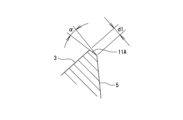
- the first cutting edge 11A described above is formed at the intersection of the clearance face 3 and the rake face 5 as shown in Figure 3, and is chamfered to a width (size) d1 and an angle ⁇ .
- the second cutting edge 11B is formed at the intersection of the clearance face 3 and the rake face 5 as shown in Figure 4, and is chamfered to a width (size) d2 and an angle ⁇ .
- the chamfer size d1 of the first cutting edge 11A can be in the range of 0.015 x D or more and 0.024 x D or less, where D is the diameter of the drill 1 with oil holes.
- Figure 5 shows a partially enlarged bottom view of the oil-hole drill 1 of the present invention
- Figure 6 shows a partially enlarged front view.
- the oil-hole drill 1 of the present invention is subjected to thinning as shown in Figure 5, and the thinning through angle ⁇ can be in the range of 32° to 42°.
- the maximum distance e from the virtual straight line L, which is a tangent to a circle S (diameter: 0.33 x D) representing the core thickness of the oil-hole drill 1 and passes through the outer corner 13 of the oil-hole drill 1, to the second cutting edge 11B can be in the range of 0.010 x D to 0.055 x D, preferably 0.010 x D to 0.034 x D, relative to the diameter D of the oil-hole drill 1.
- FIG. 7 shows an enlarged front view of the outer corner 14 of the oil-hole drill 1 of the present invention.
- the outer corners 14 of the oil-hole drill 1 can be chamfered to an angle ⁇ and width c as shown in FIG. 7.
- the angle ⁇ is in the range of 8° to 15°
- the width c is preferably in the range of 0.02 ⁇ D to 0.08 ⁇ D, where D is the diameter of the oil-hole drill 1.
- the angle ⁇ of the chamfering of the outer corners 14 can be in the range of 8° to 16.5°, preferably in the range of 8° to 15°.
- the chamfering angle ⁇ of the outer peripheral corner 14 is the angle formed by two imaginary lines: an imaginary line extending from the chamfered surface toward the outside of the oil-hole drill 1, and an imaginary line connecting the outer peripheral corner and the central axis.
- the width c is the distance (spacing) between the two imaginary lines extending from each chamfered end toward the tangent direction of the oil-hole drill 1.
- Example 1 A cutting test was conducted using the drill of the present invention (hereinafter referred to as the invention product) and a conventional drill (hereinafter referred to as the conventional product) to confirm the machining life of the drill, and the test results will be described below.
- both the invention product and the conventional product had the drill configuration shown in Figures 1 to 7, and had the same specifications of drill diameter 6 mm, flute length 139 mm, drill length 190 mm, shank diameter 6 mm, and number of cutting edges 2.
- the inventive product has a tip angle of 140°, a core thickness of 1.98 mm (33% of the drill diameter), a cutting edge clearance angle of 10°, a chamfer size of the first cutting edge of 0.10 mm (0.0166 x D), a rake angle of the thinning portion of 3°, and a maximum distance e of 0.198 mm (0.033 x D).
- the conventional product has a tip angle of 138°, a core thickness of 1.81 mm (30% of the drill diameter), a cutting edge clearance angle of 7°, a chamfer size of the first cutting edge of 0.047 mm (0.0078 x D) and 0.055 mm (0.0092 x D), a rake angle of the thinning portion of 0°, and a maximum distance e of 0.261 mm (0.044 x D).
- the work material was carbon steel (S50C), and the cutting conditions were set as follows: ⁇ Cutting speed: 120m/min ⁇ Drill speed: 6400 min-1 Drill feed speed: 1535 mm/min Feed rate: 0.24 mm/rev ⁇ Depth of drilled hole: 120mm blind hole ⁇ Cutting fluid used: Water-soluble cutting fluid (internal lubrication) ⁇ Processing machine: Horizontal M/C (HCN-4000)
- the results of this example showed that the cutting edge of the conventional product wore down as the number of machined holes increased, and when the cumulative number of machined holes from the start of cutting reached 1066 and 1160 holes, chipping occurred on the cutting edge, and the cutting test was terminated at that point.
- the cutting edge of the inventive product wore down as the number of machined holes increased, just like the conventional product, but the increase was smaller than in the case of the conventional product, and the cutting test was terminated when the cumulative number of machined holes from the start of cutting reached 1740 and 1690 holes.
- the test results showed that the number of machined holes of the inventive product increased by more than 1.5 times compared to the conventional product, and the drill life was improved compared to the conventional product.
- Example 2 Next, similarly to the above-mentioned Example 1, a cutting test was carried out using two types of drills, namely, the drill of the present invention (invention product) and a conventional drill (conventional product), and the influence on the machining life due to the change in the size of the chamfer on the first cutting edge and the maximum distance e shown in FIG. 6 was confirmed.
- the test results will be described below.
- the invention used a drill (invention) with a chamfer size of the first cutting edge: 0.140 mm (0.0233 x D), a chamfer size of the second cutting edge: 0.120 mm (0.0200 x D), and a maximum distance e: 0.197 mm (0.0328 x D).
- the conventional products used three levels of drills in total: a drill with a chamfer size of the first cutting edge: 0.063 mm (0.0105 x D), a chamfer size of the second cutting edge: 0.050 mm (0.0083 x D), and a maximum distance e: 0.261 mm (0.0435 x D) (conventional product 1), a drill with a chamfer size of the first cutting edge: 0.082 mm (0.0137 x D), a chamfer size of the second cutting edge: 0.071 mm (0.0118 x D), and a maximum distance e: 0.197 mm (0.0328 x D) (conventional product 2), and a drill with a chamfer size of the first cutting edge: 0.084 mm (0.0140 x D), and a maximum distance e: 0.227 mm (0.0378 x D) (conventional product 3). Both the inventive product and the conventional product have the drill configuration shown in Figures 1 to 7, and share the following
- Example 2 the same workpiece as in Example 1 was carbon steel (S50C), and cutting was performed under the following conditions.
- ⁇ Processing machine Horizontal M/C (HCN-4000)
- the total number of holes machined using conventional products 1 to 3 ranged from 1,008 to 1,437 holes, and there were many cases where the test was terminated due to the chisel breaking or the drill itself breaking during the test.
- the total number of holes machined using the inventive product was more than twice as many as the total number of holes machined using conventional products 1 to 3, and no drill breakage was observed during the test.
- Example 3 Next, a cutting test was carried out using two types of drills, the invention and the conventional one, with the workpiece being stainless steel (SUS304).
- the invention drill was the same as the invention drill used in Example 1, and the conventional drill had a maximum distance e of 0.294 mm (0.049 x D) and a chamfer size of 0.05 mm (0.008 x D) on the first cutting edge.
- the cutting conditions in this example were set as follows: ⁇ Cutting speed: 70m/min ⁇ Drill speed: 3715 min-1 Drill feed speed: 445 mm/min Feed rate: 0.12 mm/rev ⁇ Depth of drilled hole: 120mm blind hole ⁇ Cutting fluid used: Water-soluble cutting fluid (internal lubrication) ⁇ Processing machine: Horizontal M/C (HCN-4000)
- the cutting edge of the conventional product wore down as the number of machined holes increased, just as in Example 1, and when the cumulative number of machined holes from the start of cutting reached 543 holes, chipping occurred on the cutting edge, and the cutting test was terminated at that point.
- the cutting edge of the inventive product wore down as the number of machined holes increased, just like the conventional product, but the increase was smaller than in the case of the conventional product, and the cutting test was terminated when the cumulative number of machined holes from the start of cutting reached 2,320 holes. From the above test results, the number of machined holes of the inventive product increased by more than four times compared to the conventional product, and the drill life was improved compared to the conventional product.
- Example 4 Next, as in Example 3, a cutting test was conducted using two types of drills, one of the invention and one of the conventional drills, with stainless steel (SUS304) as the workpiece, to confirm the effect of the chamfering amount of the first cutting edge on the total number of holes machined (drill life).
- SUS304 stainless steel
- the invention product and conventional products 1 to 3 used in this example had a maximum distance e shown in Figure 6 of 0.196 mm (0.033 x D).
- the invention product used a drill with a chamfer size on the first cutting edge of 0.13 mm (0.0217 x D) (invention product).
- the conventional products used three levels of drills with chamfer sizes on the first cutting edge of 0.04 mm (0.0067 x D) (conventional product 1), 0.05 mm (0.0083 x D) (conventional product 2), and 0.08 mm (0.0133 x D) (conventional product 3).
- the cutting conditions in this example were set as follows: ⁇ Cutting speed: 70m/min ⁇ Drill speed: 3715 min-1 Drill feed speed: 445 mm/min Feed rate: 0.12 mm/rev ⁇ Depth of drilled hole: 120mm blind hole ⁇ Cutting fluid used: Water-soluble cutting fluid (internal lubrication) ⁇ Processing machine: Horizontal M/C (HCN-4000)
- the total number of holes machined using conventional products 1 to 3 ranged from 543 to 1608 holes, and in many cases the test was terminated due to drill breakage during the test.
- the total number of holes machined using the inventive product was approximately 1.5 times or more the total number of holes machined using conventional products 1 to 3, and no drill breakage was observed during the test.
- the oil-hole drill of the present invention compared to a conventional oil-hole drill, has a larger chamfering amount (size of chamfer) of the first cutting edge and a smaller maximum distance e (distance e shown in Figure 6) from the imaginary straight line L, which is a tangent to the circle S representing the core thickness of the oil-hole drill and passes through the outer corner of the oil-hole drill, to the second cutting edge, thereby reducing stress concentration on the cutting edge during cutting and at the same time maintaining the rigidity of the cutting edge.
- the drill with oil holes of the present invention improves the breakability of chips generated by cutting processing and the tool life of the drill with oil holes compared to conventional drills with oil holes.
- the drill with oil holes of the present invention is an optimal drill with oil holes for deep hole drilling of all steel materials, from general-purpose steel materials such as carbon steel to difficult-to-cut materials such as stainless steel.
Landscapes
- Engineering & Computer Science (AREA)
- Mechanical Engineering (AREA)
- Drilling Tools (AREA)
Priority Applications (1)
| Application Number | Priority Date | Filing Date | Title |
|---|---|---|---|
| JP2025521890A JPWO2024241808A1 (https=) | 2023-05-23 | 2024-04-22 |
Applications Claiming Priority (2)
| Application Number | Priority Date | Filing Date | Title |
|---|---|---|---|
| JP2023084516 | 2023-05-23 | ||
| JP2023-084516 | 2023-05-23 |
Publications (1)
| Publication Number | Publication Date |
|---|---|
| WO2024241808A1 true WO2024241808A1 (ja) | 2024-11-28 |
Family
ID=93589110
Family Applications (1)
| Application Number | Title | Priority Date | Filing Date |
|---|---|---|---|
| PCT/JP2024/015747 Ceased WO2024241808A1 (ja) | 2023-05-23 | 2024-04-22 | 油孔付ドリル |
Country Status (2)
| Country | Link |
|---|---|
| JP (1) | JPWO2024241808A1 (https=) |
| WO (1) | WO2024241808A1 (https=) |
Citations (8)
| Publication number | Priority date | Publication date | Assignee | Title |
|---|---|---|---|---|
| JPH02135111U (https=) * | 1989-04-11 | 1990-11-09 | ||
| JP2012223830A (ja) * | 2011-04-15 | 2012-11-15 | Mitsubishi Materials Corp | ドリル |
| JP2017124475A (ja) * | 2016-01-15 | 2017-07-20 | 三菱日立ツール株式会社 | ドリル |
| WO2019224862A1 (ja) * | 2018-05-21 | 2019-11-28 | オーエスジー株式会社 | ドリル |
| JP6750790B1 (ja) * | 2019-10-15 | 2020-09-02 | 住友電工ハードメタル株式会社 | ドリル |
| US20210283696A1 (en) * | 2016-12-28 | 2021-09-16 | Seco Tools Ab | Twist drill and an exchangeable head for a twist drill |
| JP2022023828A (ja) * | 2020-07-27 | 2022-02-08 | 三菱マテリアル株式会社 | ドリル |
| JP7206573B1 (ja) * | 2022-06-15 | 2023-01-18 | 住友電工ハードメタル株式会社 | ドリル |
-
2024
- 2024-04-22 WO PCT/JP2024/015747 patent/WO2024241808A1/ja not_active Ceased
- 2024-04-22 JP JP2025521890A patent/JPWO2024241808A1/ja active Pending
Patent Citations (8)
| Publication number | Priority date | Publication date | Assignee | Title |
|---|---|---|---|---|
| JPH02135111U (https=) * | 1989-04-11 | 1990-11-09 | ||
| JP2012223830A (ja) * | 2011-04-15 | 2012-11-15 | Mitsubishi Materials Corp | ドリル |
| JP2017124475A (ja) * | 2016-01-15 | 2017-07-20 | 三菱日立ツール株式会社 | ドリル |
| US20210283696A1 (en) * | 2016-12-28 | 2021-09-16 | Seco Tools Ab | Twist drill and an exchangeable head for a twist drill |
| WO2019224862A1 (ja) * | 2018-05-21 | 2019-11-28 | オーエスジー株式会社 | ドリル |
| JP6750790B1 (ja) * | 2019-10-15 | 2020-09-02 | 住友電工ハードメタル株式会社 | ドリル |
| JP2022023828A (ja) * | 2020-07-27 | 2022-02-08 | 三菱マテリアル株式会社 | ドリル |
| JP7206573B1 (ja) * | 2022-06-15 | 2023-01-18 | 住友電工ハードメタル株式会社 | ドリル |
Also Published As
| Publication number | Publication date |
|---|---|
| JPWO2024241808A1 (https=) | 2024-11-28 |
Similar Documents
| Publication | Publication Date | Title |
|---|---|---|
| US6923602B2 (en) | Drill having construction for reducing thrust load in drilling operation, and method of manufacturing the drill | |
| EP3444059B1 (en) | Small-diameter drill bit | |
| KR100853978B1 (ko) | 백테이퍼 웹을 갖는 심공 드릴 및 구멍을 뚫는 방법 | |
| US7909545B2 (en) | Ballnose end mill | |
| JP5816364B2 (ja) | 3枚刃ドリル | |
| US20150093205A1 (en) | Drill | |
| JP2008093805A (ja) | ドリル | |
| CN112351852A (zh) | 前刀面中具有多个切屑形成装置和凹陷的深孔钻 | |
| JP3337804B2 (ja) | エンドミル | |
| CN112262009A (zh) | 切削表面中具有一个或多个凹陷的深孔钻和钻具 | |
| WO2024241808A1 (ja) | 油孔付ドリル | |
| JP2003205412A (ja) | 三溝ドリル | |
| JP7400311B2 (ja) | ドリル | |
| JP7434791B2 (ja) | ドリル | |
| JP2985494B2 (ja) | 穴明け工具 | |
| JP7235627B2 (ja) | エンドミルおよびその製造方法 | |
| KR100196730B1 (ko) | 브레지드 트위스트 드릴 | |
| US20240066611A1 (en) | Cutting tool | |
| WO2025089235A1 (ja) | ドリル | |
| JP2005297169A (ja) | シャンクタイプ中ぐり工具 | |
| JP5052399B2 (ja) | めねじの加工方法 | |
| JPH0790410B2 (ja) | スモールリリーフ付き切削工具 | |
| WO2026088238A1 (ja) | ドリル | |
| JP2006192510A (ja) | ツイストドリル | |
| JP3149696B2 (ja) | ガンリーマ |
Legal Events
| Date | Code | Title | Description |
|---|---|---|---|
| 121 | Ep: the epo has been informed by wipo that ep was designated in this application |
Ref document number: 24810816 Country of ref document: EP Kind code of ref document: A1 |
|
| ENP | Entry into the national phase |
Ref document number: 2025521890 Country of ref document: JP Kind code of ref document: A |
|
| WWE | Wipo information: entry into national phase |
Ref document number: 2025521890 Country of ref document: JP |
|
| NENP | Non-entry into the national phase |
Ref country code: DE |