WO2024241785A1 - メス型端子、コネクタ、端子付き電線、コネクタ付き電線及びワイヤーハーネス - Google Patents
メス型端子、コネクタ、端子付き電線、コネクタ付き電線及びワイヤーハーネス Download PDFInfo
- Publication number
- WO2024241785A1 WO2024241785A1 PCT/JP2024/015513 JP2024015513W WO2024241785A1 WO 2024241785 A1 WO2024241785 A1 WO 2024241785A1 JP 2024015513 W JP2024015513 W JP 2024015513W WO 2024241785 A1 WO2024241785 A1 WO 2024241785A1
- Authority
- WO
- WIPO (PCT)
- Prior art keywords
- terminal
- spring
- arm
- connector
- harness
- Prior art date
- Legal status (The legal status is an assumption and is not a legal conclusion. Google has not performed a legal analysis and makes no representation as to the accuracy of the status listed.)
- Ceased
Links
Images





Classifications
-
- H—ELECTRICITY
- H01—ELECTRIC ELEMENTS
- H01R—ELECTRICALLY-CONDUCTIVE CONNECTIONS; STRUCTURAL ASSOCIATIONS OF A PLURALITY OF MUTUALLY-INSULATED ELECTRICAL CONNECTING ELEMENTS; COUPLING DEVICES; CURRENT COLLECTORS
- H01R13/00—Details of coupling devices of the kinds covered by groups H01R12/70 or H01R24/00 - H01R33/00
- H01R13/02—Contact members
- H01R13/22—Contacts for co-operating by abutting
- H01R13/24—Contacts for co-operating by abutting resilient; resiliently-mounted
- H01R13/2407—Contacts for co-operating by abutting resilient; resiliently-mounted characterized by the resilient means
-
- H—ELECTRICITY
- H01—ELECTRIC ELEMENTS
- H01R—ELECTRICALLY-CONDUCTIVE CONNECTIONS; STRUCTURAL ASSOCIATIONS OF A PLURALITY OF MUTUALLY-INSULATED ELECTRICAL CONNECTING ELEMENTS; COUPLING DEVICES; CURRENT COLLECTORS
- H01R13/00—Details of coupling devices of the kinds covered by groups H01R12/70 or H01R24/00 - H01R33/00
- H01R13/02—Contact members
- H01R13/15—Pins, blades or sockets having separate spring member for producing or increasing contact pressure
- H01R13/187—Pins, blades or sockets having separate spring member for producing or increasing contact pressure with spring member in the socket
-
- H—ELECTRICITY
- H01—ELECTRIC ELEMENTS
- H01R—ELECTRICALLY-CONDUCTIVE CONNECTIONS; STRUCTURAL ASSOCIATIONS OF A PLURALITY OF MUTUALLY-INSULATED ELECTRICAL CONNECTING ELEMENTS; COUPLING DEVICES; CURRENT COLLECTORS
- H01R13/00—Details of coupling devices of the kinds covered by groups H01R12/70 or H01R24/00 - H01R33/00
- H01R13/02—Contact members
- H01R13/10—Sockets for co-operation with pins or blades
- H01R13/11—Resilient sockets
- H01R13/113—Resilient sockets co-operating with pins or blades having a rectangular transverse section
-
- H—ELECTRICITY
- H01—ELECTRIC ELEMENTS
- H01R—ELECTRICALLY-CONDUCTIVE CONNECTIONS; STRUCTURAL ASSOCIATIONS OF A PLURALITY OF MUTUALLY-INSULATED ELECTRICAL CONNECTING ELEMENTS; COUPLING DEVICES; CURRENT COLLECTORS
- H01R13/00—Details of coupling devices of the kinds covered by groups H01R12/70 or H01R24/00 - H01R33/00
- H01R13/58—Means for relieving strain on wire connection, e.g. cord grip, for avoiding loosening of connections between wires and terminals within a coupling device terminating a cable
- H01R13/582—Means for relieving strain on wire connection, e.g. cord grip, for avoiding loosening of connections between wires and terminals within a coupling device terminating a cable the cable being clamped between assembled parts of the housing
-
- H—ELECTRICITY
- H01—ELECTRIC ELEMENTS
- H01R—ELECTRICALLY-CONDUCTIVE CONNECTIONS; STRUCTURAL ASSOCIATIONS OF A PLURALITY OF MUTUALLY-INSULATED ELECTRICAL CONNECTING ELEMENTS; COUPLING DEVICES; CURRENT COLLECTORS
- H01R4/00—Electrically-conductive connections between two or more conductive members in direct contact, i.e. touching one another; Means for effecting or maintaining such contact; Electrically-conductive connections having two or more spaced connecting locations for conductors and using contact members penetrating insulation
- H01R4/02—Soldered or welded connections
- H01R4/023—Soldered or welded connections between cables or wires and terminals
-
- H—ELECTRICITY
- H01—ELECTRIC ELEMENTS
- H01R—ELECTRICALLY-CONDUCTIVE CONNECTIONS; STRUCTURAL ASSOCIATIONS OF A PLURALITY OF MUTUALLY-INSULATED ELECTRICAL CONNECTING ELEMENTS; COUPLING DEVICES; CURRENT COLLECTORS
- H01R4/00—Electrically-conductive connections between two or more conductive members in direct contact, i.e. touching one another; Means for effecting or maintaining such contact; Electrically-conductive connections having two or more spaced connecting locations for conductors and using contact members penetrating insulation
- H01R4/02—Soldered or welded connections
- H01R4/029—Welded connections
Definitions
- This invention relates to a connector that is attached to a housing that houses electrical equipment such as a motor or power supply equipment such as a battery, and that is connected to a connector provided in an electrical circuit that is connected to the electrical equipment, a female terminal that is attached to the connector, an electric wire with a terminal, an electric wire with a connector, and a wire harness.
- a harness-side connector (hereinafter referred to as a harness-side connector) as shown in Patent Document 1 is connected to an equipment-side connector (hereinafter referred to as an equipment-side connector) provided on a housing of an equipment such as a motor.
- connection terminal hereinafter referred to as a female terminal
- a connection terminal hereinafter referred to as a male terminal
- the plate-shaped male terminal protruding from inside the device-side connector mates with the terminal connection portion of the female terminal arranged inside the harness-side connector, establishing a conductive connection.
- the terminal connection portion of the female terminal arranged on the harness side connector has a pair of side walls that face each other in a direction that intersects with the mating direction of the harness side connector and the device side connector, and a plate-shaped male terminal is inserted into the insertion space between the side walls.
- a spring plate having a plurality of arm springs is provided on the inner surfaces of the pair of side walls of the female terminal, the spring plate having a plurality of arm springs that biases and abuts against the inserted plate-like male terminal. Therefore, the plate-shaped male terminal inserted into the insertion space of the female terminal is electrically connected to the female terminal via the spring plate material having multiple arm springs that abut against it while applying a force.
- the arm springs have contact parts at their tips that protrude toward the plate-shaped male terminal to ensure that they abut against the plate-shaped male terminal.
- the attachment state of the spring plate material to the female terminal is controlled by whether the contact parts are in a predetermined position.
- This invention is characterized in that it comprises a terminal body connected to an electric wire and a spring member attached to the terminal body, the terminal body having a pair of side walls arranged at a predetermined interval and forming an insertion space into which a male terminal can be inserted, the spring member having a plurality of arm springs that abut against the male terminal inserted into the insertion space, the arm springs being arranged parallel to the insertion direction of the male terminal into the insertion space, and being arranged in a plurality of directions in which the side walls face each other and in an orthogonal direction perpendicular to the insertion direction and in the insertion direction, the arm springs being provided with contact portions that protrude so as to abut against the male terminal, and the contact portions of the arm springs arranged in a plurality of directions in the insertion direction being arranged offset in the orthogonal direction to form a female terminal.
- the present invention is also characterized in that it is a connector comprising any one of the female terminals described above and a connector housing that accommodates the female terminal, and further comprising an electric wire with terminal comprising the female terminal described above and the electric wire that is connected to the terminal body of the female terminal.
- the present invention is characterized in that it is an electric wire with a connector that includes the above-mentioned electric wire with terminal and a connector housing that accommodates the electric wire with terminal, and further, a wire harness that includes the above-mentioned electric wire with terminal, or a wire harness that includes the above-mentioned electric wire with connector.
- the mounting state of the spring member, which has a plurality of arm springs arranged along the insertion direction, in the female terminal can be managed by confirming the positions of the respective contact portions.
- the terminal has a pair of side walls arranged at a predetermined distance and forming an insertion space into which a male terminal can be inserted, and a spring member attached to a terminal body connected to an electric wire has a plurality of arm springs that abut against the male terminal inserted into the insertion space, and the arm springs are arranged parallel to the insertion direction of the male terminal into the insertion space, and are arranged in multiple directions, facing the side walls and perpendicular to the insertion direction, and in the insertion direction.
- the arm spring is provided with a contact portion that protrudes so as to come into contact with the male terminal, and the contact portions of the arm springs arranged in multiple locations in the insertion direction are arranged offset in the orthogonal direction. Therefore, the contact portions of the arm springs arranged in multiple locations in the insertion direction that are offset in the orthogonal direction can be confirmed from the insertion direction. Therefore, it is possible to confirm the positions of not only the contact portions of the arm springs on the front side in the insertion direction, but also the contact portions of the arm springs on the rear side in the insertion direction, and manage the mounting state of the spring member at the female terminal.
- the contact portions provided on the arm springs arranged in multiple numbers in the insertion direction may be arranged offset in the orthogonal direction, or the arm springs arranged in multiple numbers in the insertion direction may be arranged offset in the orthogonal direction, or further, the arm springs arranged in multiple numbers in the insertion direction and the contact portions provided on the arm springs may be arranged offset in the orthogonal direction.
- the contact portions provided on the arm springs arranged in multiple numbers in the insertion direction may be arranged at different positions in the orthogonal direction, the arm springs arranged in multiple numbers in the insertion direction may be arranged at different positions in the orthogonal direction, or further, the arm springs arranged in multiple numbers in the insertion direction and the contact portions provided on the arm springs may be arranged at different positions in the orthogonal direction.
- the contact portions of the arm springs arranged in the insertion direction can be reliably arranged so as to be shifted in the orthogonal direction.
- the arm springs may be arranged in two tiers in the insertion direction, and the arm springs arranged in two tiers may be formed so as to be close to each other in an opposing direction from the base end side to the tip end side in the insertion direction.
- the arm spring is inclined along the insertion direction, so that the number of contacts can be increased without interfering with the insertion of the male terminal into the insertion space.
- This invention provides a female terminal, connector, electric wire with terminal, electric wire with connector, and wire harness that can manage the attachment state of a female terminal of a spring member having multiple arm springs arranged along the insertion direction by checking the position of each contact part.
- FIG. FIG. FIG. FIG. FIG. FIG. 4 is a perspective view illustrating assembly of the device-side connector.
- FIG. FIG. FIG. 2 is a perspective view of a terminal harness;
- FIG. 2 is an explanatory diagram of a harness with terminals.
- FIG. 4 is a perspective view illustrating assembly of the terminal harness;
- FIG. 1 shows an explanatory diagram of a connector connection structure 1
- FIGS. 2 and 3 show perspective views of the connector connection structure 1 in a separated state.
- Fig. 1(a) is a perspective view of the connector connection structure 1 as viewed from the front, left side and bottom
- Fig. 1(b) is a perspective view of the connector connection structure 1 as viewed from the back, right side and bottom
- Fig. 2 is an exploded perspective view of the connector connection structure 1 as viewed from the front, left side and bottom
- Fig. 3 is an exploded perspective view of the connector connection structure 1 as viewed from the back, right side and bottom.
- FIG. 4 and 5 are exploded perspective views of the device-side connector 10,
- FIG. 6 is a perspective view illustrating the assembly of the device-side connector 10
- FIG. 4 is an exploded perspective view of the device-side connector 10 as viewed from the front, left side and bottom
- FIG. 5 is an exploded perspective view of the device-side connector 10 as viewed from the back, right side and bottom.
- Fig. 6(a) shows a perspective view of the device-side connector 10 in a disassembled state as viewed from the front, left side, and bottom
- Fig. 6(b) shows a perspective view of the device-side connector 10 as viewed from the front, left side, and bottom.
- Figs. 4 to 6 show the hood portion 142 of the male housing 14 in the device-side connector 10 in a see-through state.
- FIG. 7(a) shows a right side view of the equipment side connector 10 before the male terminals 11 are assembled
- Figure 7(b) shows a cross-sectional view taken along the line A-A in Figure 7(a)
- Figure 7(c) shows a cross-sectional view taken along the line B-B in Figure 7(b)
- Figure 7(d) shows a right side view of the equipment side connector 10 with the male terminals 11 assembled
- Figure 7(e) shows a cross-sectional view taken along the line C-C in Figure 7(d)
- Figure 7(f) shows a cross-sectional view taken along the line D-D in Figure 7(e).
- FIG. 8 shows an exploded perspective view of the harness-side connector 20 as viewed from the front, left side and bottom
- FIG. 9 shows an exploded perspective view of the harness-side connector 20 as viewed from the back, right side and bottom.
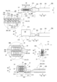
- FIG. 10 shows an explanatory diagram of a perspective view of the harness with terminals 204
- FIG. 11 shows an explanatory diagram of the harness with terminals 204
- FIG. 12 shows an explanatory diagram of the assembly of the harness with terminals 204 using a perspective view
- FIG. 13 shows an explanatory diagram of the harness side connector 20
- FIG. 14 shows an explanatory diagram of the connector connection structure 1.
- FIG. 10(a) shows a perspective view of the harness with terminals 204 provided in the harness-side connector 20 from the back, left side and top
- FIG. 10(b) shows a perspective view of the harness with terminals 204 from the front, right side and top.
- Fig. 11(a) shows a rear view of the harness with terminals 204
- Fig. 11(b) shows a right side view of the harness with terminals 204
- Fig. 11(c) shows a cross-sectional view taken along the line E-E in Fig. 11(b)
- Fig. 11(d) shows a cross-sectional view taken along the line F-F in Fig. 11(c).
- Fig. 11 shows an enlarged view of part a in Fig. 11(a), and an enlarged view of part b in Fig. 11(d).
- FIG. 12(a) shows a perspective view of the harness with terminals 204 in a disassembled state as viewed from the back, left side, and top
- FIG. 12(b) shows a perspective view of the harness with terminals 204 as viewed from the back, left side, and top.
- Fig. 13(a) shows a right side view of the harness side connector 20, and Fig. 13(b) shows a cross-sectional view taken along line G-G in Fig. 13(a).
- Fig. 13 shows an enlarged view of part c in Fig. 13(b).
- Fig. 14 shows a front view, a left side view and a bottom view of the connector connection structure 1, and Fig. 14(b) shows a cross-sectional view taken along the line H-H in Fig. 14(a).
- Fig. 14 shows an enlarged view of part d in Fig. 14(b).
- the up-down direction in FIG. 1(a) is the height direction H
- the direction connecting the top left and bottom right is the width direction W
- the direction connecting the bottom left and top right is the depth direction D.
- the upper side in the up-down height direction H is the upper side Hu
- the lower side is the lower side Hd
- the upper right side in the depth direction D connecting the bottom left and top right is the front side Df
- the lower left side is the back side Db.
- the direction in which the device-side connector 10 and the harness-side connector 20 are attached and detached is defined as the depth direction D.
- the direction in which the harness-side connector 20 is attached to the device-side connector 10 is defined as the back side Db
- the direction in which the harness-side connector 20 is removed from the device-side connector 10 is defined as the front side Df.
- the directions perpendicular to the depth direction D are set as the width direction W and the height direction H.
- the above-mentioned directions are commonly used in each drawing in this specification for explanation.
- the female terminal 21 of the present invention can manage the mounting state of the spring plate material 30, which has multiple arm springs 31 arranged along the height direction H, in the female terminal 21 by checking the position of each contact portion 34 (34a, 34b). Therefore, the female terminal 21 is provided with a terminal body 210 connected to the high-voltage wire 201, and a spring plate material 30 attached to the terminal body 210, and the terminal body 210 has a pair of side walls 213 arranged at a predetermined interval and forming an insertion space S into which the plate-shaped connection portion 111 of the male terminal 11 can be inserted.
- the spring plate material 30 has multiple arm springs 31 that abut against the plate-shaped connection portion 111 of the male terminal 11 inserted into the insertion space S.
- the arm springs 31 are arranged parallel to the depth direction D of the plate-shaped connection portion 111 of the male terminal 11 into the insertion space S, and are arranged in multiple directions in the height direction H, which is perpendicular to the width direction W and depth direction D of the side wall 213, and in the depth direction D.
- the arm spring 31 is provided with a contact portion 34 that protrudes so as to come into contact with the plate-like connection portion 111 of the male terminal 11, and the contact portions 34 (34a, 34b) of the arm springs 31 (31a, 31b) arranged in the depth direction D are arranged so as to be shifted from each other in the height direction H.
- the contact portions 34 (34a, 34b) of the arm springs 31 (31a, 31b) arranged in the depth direction D are arranged at different positions in the height direction H. Therefore, the mounting state of the spring plate material 30 having a plurality of arm springs 31 provided along the depth direction D in the female terminal 21 can be managed by confirming the positions of each contact portion 34 (34a, 34b).
- the harness side connector 20 having the above-mentioned female terminal 21, the device side connector 10, and the connector connection structure 1 connecting the device side connector 10 and the harness side connector 20 are described in detail below.
- the connector connection structure 1 is a connection structure that can establish an electrically and physically stable connection state by fitting and connecting an equipment side connector 10, which is connected to an electrical circuit that is connected to electrical equipment such as an electrical device such as a motor or an electrical device such as a power supply device equipped in an automobile or the like, and a harness side connector 20 attached to a wire harness 200 that bundles high-voltage wires 201, in the depth direction D.
- an equipment side connector 10 which is connected to an electrical circuit that is connected to electrical equipment such as an electrical device such as a motor or an electrical device such as a power supply device equipped in an automobile or the like
- a harness side connector 20 attached to a wire harness 200 that bundles high-voltage wires 201, in the depth direction D.
- the mounting base 70 is attached to the device housing 60, a portion of which is shown by a dashed line, and serves as a base for fixing the male housing 14 and the harness side connector 20, which will be described later.
- the mounting base 70 has a vertically elongated rectangular shape that is longer in the height direction H than in the width direction W, with a through hole 71 penetrating in the depth direction D at the center when viewed from the front, and has a predetermined thickness in the depth direction D.
- the main surface on the front side of the mounting base 70 is a fixing main surface 72 for fixing the harness side connector 20 to be attached, and a cylindrical fixing protrusion 73 protruding toward the front side Df is provided on the lower side Hd of the through hole 71 in the fixing main surface 72, and a screw hole 74 is provided at the top of the fixing protrusion 73 into which a fixing bolt 29 (see Figures 2 and 3) for bolting the harness side connector 20 is screwed.
- the main fixing surface 72 above the through hole 71 has a screw hole 75 at the center in the width direction W for fixing the male housing 14 (described later) with a fixing bolt (not shown).
- the mounting base 70 configured in this manner is made of metal.
- the screw hole 75 into which the fixing bolt (not shown) that screws into and fixes the male housing 14 and the screw hole 74 provided in the fixing protrusion 73 that screws into the harness side connector 20 to the mounting base 70 are provided at positions on the mounting base 70 that face each other in the height direction H, sandwiching the through hole 71 into which the male terminal 11 is attached.
- the mounting base 70 thus configured is attached by an appropriate method to the device housing 60 in which the electric device is disposed.
- the equipment side connector 10 which is attached to a mounting base 70 attached to an equipment housing 60, includes a male terminal 11, an equipment side seal 13, a male housing 14, and a fixing bolt (not shown), as shown in Figures 4 and 5.
- the male terminal 11 is connected to an electrical circuit connected to an electrical device arranged inside the equipment housing 60, and is also connected to a female terminal 21 arranged inside the harness side connector 20, and two of them are provided, spaced a predetermined distance apart in the width direction W.
- the male terminal 11 is made of a metal plate, and includes a plate-shaped connection portion 111, a coupling portion 112, and a circuit connection portion 113 arranged in this order in the depth direction D from the front side Df to the back side Db.
- the plate-shaped connection portion 111 is inserted into the insertion space S formed between the side walls 213 of the terminal connection portion 212 in the female terminal 21 by connecting the harness side connector 20 and the equipment side connector 10, and is connected to the female terminal 21 via the spring plate material 30.
- the connecting portion 112 connects the plate-shaped connecting portion 111 and the circuit connecting portion 113, and the circuit connecting portion 113 is connected to an electrical circuit (not shown) that is connected to an electrical device arranged inside the device housing 60.
- the plate-shaped connection portion 111, the linking portion 112, and the circuit connection portion 113 are formed continuously in the depth direction D, and the main surface of the plate material is formed in a flat shape along the height direction H and the width direction W.
- the plate-shaped connection portion 111 that connects to the female terminal 21 is disposed inside the hood portion 142 of the male housing 14 described later, and protrudes forward Df from the main body portion 141 of the male housing 14 described later.
- the connecting portion 112 which is continuous with the plate-shaped connecting portion 111, is formed to a length that penetrates the main body portion 141 and the insertion tube portion 143 of the male housing 14 described below in the depth direction D.
- the circuit connecting portion 113 is formed to protrude from the insertion tube portion 143 to the rear side Db.
- the device side seal 13 is a ring-shaped rubber seal member that is attached to the insertion tube portion 143 of the male housing 14 (described later) and seals between the insertion tube portion 143 of the male housing 14 and the mounting base 70.
- the male housing 14 is for holding the male terminal 11 on the mounting base 70, and includes a main body portion 141 that holds the male terminal 11, a hood portion 142 that surrounds the male terminal 11 held by the main body portion 141, a cylindrical insertion tube portion 143 that is inserted into the through hole 71 of the mounting base 70, and a fixing protrusion portion 144 that fixes the male housing 14 to the mounting base 70 with a fixing bolt (not shown).
- the main body portion 141 is formed in a generally rectangular shape that is slightly longer in the height direction H than in the width direction W when viewed from the depth direction D.
- the main body portion 141 is provided with a terminal holding portion 146 that protrudes toward the front side Df.
- the hood portion 142 is formed in the shape of a peripheral wall, with an opening on the front side Df, and both sides in the depth direction D and an upper side Hu protruding toward the front side Df from the main body portion 141.
- the hood portion 142 is formed so that the upper side Hu protrudes toward the front side Df more than the lower side Hd.
- the insertion tube portion 143 is located on the rear side Db of the main body portion 141, and is formed in a disk shape with a diameter slightly smaller than the diameter of the through hole 71 of the mounting base 70 so that it can be inserted into the through hole 71, and is formed to be one size thicker than the thickness of the mounting base 70 in the depth direction D.
- the fixing protrusion 144 protrudes from the center in the width direction W to the upper side Hu of the main body portion 141, and has a mounting hole for mounting a fixing bolt (not shown) that screws into and fixes the male housing 14 to the screw hole 75 of the mounting base 70.
- the male terminal 11 to be assembled penetrates the main body portion 141 and the insertion tube portion 143 in the depth direction D, and the male terminal 11 can be held by the terminal holding portion 146 that protrudes forward Df from the main body portion 141.
- the insertion tube portion 143, the main body portion 141, and the terminal holding portion 146 are provided with through holes in the depth direction D through which the male terminal 11 can be inserted, and the male terminal 11 inserted into the through hole is held by the male housing 14.
- the terminal holder 146 protrudes from the main body 141 toward the front side Df, and an extension 147 protrudes further toward the front side Df.
- the extension body 147 is formed in a gate-shaped frame shape when viewed from the width direction W so as to follow the peripheral edge of the plate-shaped connection portion 111 that protrudes toward the front side Df from the terminal holding portion 146 of the male terminal 11 held by the terminal holding portion 146.
- the extension body 147 has two pillars 148 that protrude from the terminal holding portion 146 toward the near side Df, along the side edges of the plate-shaped connection portion 111 that protrudes from the terminal holding portion 146 toward the near side Df, and a tip connecting portion 149 that spans and connects the tips of the pillars 148 to each other in the height direction H, along the tip edge of the plate-shaped connection portion 111.
- the two pillars 148 are arranged so that the distance between their inner faces corresponds to the width of the plate-shaped connection part 111 in the height direction H, and the tip connecting part 149 that spans between their tips forms a gate-shaped frame with an internal space Is of approximately the same shape as the plate-shaped connection part 111 when viewed from the width direction W.
- the two pillars 148 that make up the gate-shaped extension body 147 are pillars with a rectangular cross section, but are formed to be thicker than the plate-shaped connection part 111.
- the thickness of the pillars 148 is formed to be thinner than the distance between the inner surfaces of the side walls 213 of the female terminal 21 to which the male terminal 11 is connected.
- the thickness of the pillar portion 148 is thicker than the thickness of the plate-shaped connection portion 111, and is thinner than the distance between the inner surfaces of the spring mounting portions 32 of the spring plate material 30 provided on the inner surface of the side wall 213 of the female terminal 21 to which the male terminal 11 is connected.
- the tip coupling portion 149 is formed to have a thickness approximately equal to that of the plate-like connecting portion 111, and a width greater than the thickness.
- the pillar portion 148 and the tip of the front side Df of the tip coupling portion 149 are formed so as to be gradually thinner.
- the device-side connector 10 having each of the elements thus configured is made of resin and is integrally constructed.
- the device-side connector 10 having the individual elements thus configured is assembled by assembling the male terminals 11 into the main body portion 141 of the male housing 14 and fitting the device-side seal 13 onto the insertion tube portion 143 .
- the connecting portion 112 is inserted through the insertion tube portion 143, the main body portion 141 and the terminal holding portion 146 so that the plate-like connecting portion 111 is disposed inside the hood portion 142, and the male terminal 11 is attached to the male housing 14 so that the circuit connecting portion 113 protrudes from the insertion tube portion 143 to the rear side Db.
- the plate-like connecting portion 111 is disposed in the internal space Is of the extension body 147 that protrudes from the terminal holding portion 146 to the front side Df.
- the high-voltage wire 201 having the male terminal 11 attached to the tip thereof is called a terminal harness, and the male terminal 11 of the terminal harness is disposed inside the device-side connector 10 to form a connector-equipped electric wire.
- the harness side connector 20 that constitutes the connector connection structure 1 by being connected to the above-mentioned device-side connector 10 will be described with reference to Figs. 8 to 13 .
- the harness side connector 20 is attached to the above-mentioned device side connector 10 to constitute the connector connection structure 1, and is a connector that connects the male terminals 11 of the device side connector 10 to the female terminals 21 arranged inside.
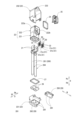
- the harness side connector 20 (20a) includes a wire harness 200, a female terminal 21 attached to the end of a high-voltage wire 201 that constitutes the wire harness 200, an internal housing 22, a housing shell 23, a housing seal 24, a housing cover 25, a wire seal 26, a shell seal 27, and a wire holding portion 28.
- the high-voltage wire 201 with the female terminal 21 attached to its end is called a terminal-equipped harness 204.
- the female terminal 21 is a high-voltage terminal attached to the wire conductor 202 exposed from the tip of the high-voltage wire 201, which is covered with an insulating coating 203.
- a female terminal 21 is attached to each high-voltage wire 201, and the harness side connector 20 has two female terminals 21. Details of the female terminals 21 will be described later.
- the internal housing 22 holds the two female terminals 21 at a predetermined position inside the harness side connector 20, and includes a harness insertion tube 221 through which the wire harness 200 is inserted, and a holding body 222 that holds the female terminals 21 provided at the tip of the wire harness 200 inserted into the harness insertion tube 221.
- the internal housing 22 is made of resin.
- the harness insertion tube portion 221 is a square tube having an open end (lower end) on the lower side Hd, and an open end (upper end) on the upper side Hu that communicates with the inside of the holder main body 222 .
- a through hole is provided at the upper side Hu and at the center in the width direction W of the harness insertion tube portion 221, through which a fixing bolt 29 described later can pass in the depth direction D.
- the holding portion main body 222 is disposed at the end of the upper side Hu of the harness insertion tube portion 221, has a generally rectangular parallelepiped shape with an open back side Db, and is configured to hold the female terminal 21 therein. As shown in FIG. 9, the holding portion main body 222 is configured with a double wall of an outer wall 222a and an inner wall 222b, and is configured to hold the female terminal 21 inside the inner wall 222b.
- the space between the outer wall 222a and the inner wall 222b is where the hood portion 142 of the male housing 14 of the device-side connector 10 (described later) is inserted when the device-side connector 10 and the harness-side connector 20 are assembled, and where the housing seal 24 is attached.
- the housing shell 23 covers the outside of the inner housing 22 and forms the outer shape of the harness side connector 20 .
- the housing shell 23 is slightly larger than the inner housing 22 and includes a harness insertion tube outer portion 231 and a shell body 232 .
- the harness insertion tube exterior 231 is a square cylindrical body that is slightly larger than the harness insertion tube portion 221 so that the harness insertion tube portion 221, through which the wire harness 200 is inserted, is positioned inside, and the end of the upper side Hu is connected to the interior of the shell main body 232.
- the lower side Hd of the harness insertion tube exterior 231 serves as an electric wire holding portion 28 .
- the shell body 232 is disposed at the end of the upper side Hu of the harness insertion tube exterior 231, is larger than the retaining portion body 222 disposed inside, and has a generally rectangular parallelepiped shape with an open back side Db.
- the female terminal 21 is exposed on the back side Db as a fitting opening 235 (see FIG. 3 ).
- the shell body 232 is provided with a cover portion 233 on the upper side Hu.
- the cover portion 233 has a triangular pyramid shape when viewed from the front, protruding upward Hu from the shell main body 232, and is formed to surround the fixing protrusion 144 and fixing bolt (not shown) that fix the male housing 14 of the equipment side connector 10 to the mounting base 70 provided on the equipment housing 60.
- the housing shell 23 that contains the inner housing 22 is made of metal, and is configured by assembling a harness insertion tube outer part 231 and a shell body 232 .
- the housing seal 24 is made of rubber and has a ring shape that is generally rectangular in plan view, which matches the shape of the inner wall 222b of the holder main body 222 when viewed from behind.
- the housing seal 24 is a sealing material that fits over the inner wall 222b of the inner housing 22 and seals between the hood portion 142 of the male housing 14 of the equipment side connector 10 (described later) and the inner housing 22 of the harness side connector 20 when the equipment side connector 10 and the harness side connector 20 are assembled.
- the housing cover 25 is attached to the inner wall 222b of the internal housing 22 from the rear side Db to secure the housing seal 24 arranged in the holding portion main body 222 of the internal housing 22 and to hold the female terminal 21 arranged inside the holding portion main body 222. It is made of resin.
- the wire seal 26 is rectangular in plan view and has an insertion hole 261 through which the high-voltage wire 201 passes, and is a sealing member that seals the gap between the high-voltage wire 201 inserted into the harness insertion tube 221 and the inner surface of the harness insertion tube 221. Therefore, two wire seals 26 are provided corresponding to the two high-voltage wires 201.
- the shell seal 27 is a sealing member that fits around the harness insertion tube portion 221 of the internal housing 22 and seals the space between the harness insertion tube portion 221 and the harness insertion tube exterior 231.
- the shell seal 27 is formed in a roughly rectangular frame shape that can be fitted around the harness insertion tube portion 221.
- the electric wire holding portion 28 provided at the end of the lower side Hd of the harness insertion tube exterior 231 holds the high-voltage electric wire 201 inserted into the harness insertion tube portion 221 in the harness insertion tube exterior 231, and has an electric wire insertion hole 281 through which the high-voltage electric wire 201 is inserted.
- Two electric wire insertion holes 281 are provided at a predetermined distance in the width direction W to correspond to the two high-voltage wires 201 that make up the wire harness 200, and the electric wire insertion holes 281 are formed to have the same diameter as or slightly smaller than the outer diameter of the high-voltage wires 201 that are inserted.
- the electric wire holding portion 28 is provided on the lower side Hd of the harness insertion tube exterior 231 with a fixed side holding portion 282 that is integral with the harness insertion tube exterior 231, and an attachment holding portion 283 that is attached to the fixed side holding portion 282, and is equipped with a fixing bolt (not shown) that fixes the attachment holding portion 283 assembled to the fixed side holding portion 282.
- the mounting holder 283 is attached to the fixed side holder 282 of the harness insertion tube exterior 231, and a fixing bolt (not shown) is screwed in to fix the mounting holder 283 to the fixed side holder 282, thereby forming the electric wire holder 28.
- the harness side connector 20 which has each element configured in this way, is fitted and connected to the device side connector 10, which will be described later.
- the fixing bolt 29, which fixes the connection, is a metal bolt with a bolt head provided at the end of the screw shaft that screws into the screw hole 74 provided in the fixing protrusion 73 of the mounting base 70.
- the female terminal 21 disposed inside the harness side connector 20 will be described with reference to FIGS.
- the female terminal 21 is a high-voltage terminal connected to the wire conductor 202 exposed from the insulating coating 203 at the tip of the two high-voltage wires 201, and the high-voltage wire 201 with the female terminal 21 connected to its tip is formed as a terminal-equipped harness 204.
- the female terminal 21 constituting the terminal harness 204 is composed of a terminal body 210 provided with a wire connection portion 211 that connects the wire conductor 202 of the high-voltage cable 201 and a terminal connection portion 212 to which the plate-shaped connection portion 111 ( Figure 10) of the male terminal 11 is connected, and is arranged in this order from the lower side Hd to the upper side Hu along the height direction H.
- the electric wire connection portion 211 is formed in a square U-shape with an open back side Db when viewed from the height direction H.
- the terminal connection portion 212 is formed in a roughly U-shape with an open rear side Db when viewed from the height direction H, and is composed of two side walls 213 spaced a predetermined distance apart in the width direction W and a lower connecting portion 214 connecting the lower ends of the side walls 213.
- the space between the side walls 213 facing each other in the width direction W is an insertion space S (FIG. 11) into which the plate-shaped connecting portion 111 of the male terminal 11 described later is inserted for connection.
- the side walls 213 are longer in the height direction H than in the depth direction D, and are rectangular when viewed in the width direction W.
- the lower connecting parts 214 are arranged at a predetermined interval in the height direction H, so that through holes 215 that penetrate in the depth direction D are formed between the lower connecting parts 214 (see FIG. 10(b)).
- the spring plate material 30 is formed into a substantially square shape by punching a metal plate.
- the spring plate material 30 has ten arm springs 31 that contact the plate-shaped connection parts 111 (see FIG. 13 ) of the male terminals 11, and spring attachment parts 32 that surround the arm springs 31 and are attached to the side walls 213.
- the spring attachment portion 32 is formed in a substantially rectangular frame shape, supports the arm spring 31 extending inward in the depth direction D, and is provided with a welded portion 33 (see FIG. 11( d )) that fixes it to the inner surface of the side wall 213 .
- Five of the ten arm springs 31 are disposed on the rear side Db, arranged in parallel in the height direction H, and extend from the rear side Db supported by the spring attachment portion 32 toward the front side Df.
- the remaining five arm springs 31 are disposed on the front side Df, arranged in parallel in the height direction H, and extend from the front side Df supported by the spring attachment portion 32 toward the rear side Db.
- the number of arm springs 31 is not limited to the above number, and may be any appropriate number.
- the arm springs 31 are arranged in two tiers in the depth direction D, with the five arm springs 31 that extend from the rear side Db supported by the spring mounting portion 32 toward the front side Df being the opening side arm springs 31a that are closer to the opening of the insertion space S. And the five arm springs 31 that extend from the front side Df supported by the spring mounting portion 32 toward the rear side Db being the connecting side arm springs 31b that are closer to the lower connecting portion 214.
- the five opening-side arm springs 31a close to the opening of the insertion space S and the five connecting-side arm springs 31b close to the lower connecting portion 214 are offset from each other in the height direction H.
- the opening-side arm springs 31a and the connecting-side arm springs 31b are offset from each other in the height direction H by about half the distance between the two contact portions 34 provided on the inner arm springs 31 among the five arm springs 31 lined up in the height direction H.
- the arm springs 31 on both sides of the arm springs 31 arranged in parallel in the height direction H are formed to be wider than the other arm springs 31 .
- the contact portion 34 is formed by bending at the tip side of the arm spring 31 so as to protrude toward the other side in the width direction W.
- the contact portions 34 configured in this manner are formed in pairs at the tip side of the arm spring 31, spaced apart by a predetermined distance in the height direction H. Specifically, of the five arm springs 31 lined up in the height direction H, two contact portions 34 are formed spaced apart by a distance of about half the width of the tip side of the inner arm spring 31.
- the contact portion 34 at the opening side arm spring 31a is referred to as the opening side contact portion 34a
- the contact portion 34 at the connecting side arm spring 31b is referred to as the connecting side contact portion 34b.
- the opening side contact portion 34a provided on the opening side arm spring 31a and the connecting side contact portion 34b provided on the connecting side arm spring 31b, which are arranged offset in the height direction H, are arranged offset in the height direction H, and as shown in the enlarged view of part a in Figure 11 (a), the opening side contact portion 34a of the opening side arm spring 31a and the connecting side contact portion 34b of the connecting side arm spring 31b can each be seen from the rear side Db of the terminal connection portion 212.
- the spring plate materials 30 thus configured are attached to the inner surfaces of the pair of side walls 213, and are arranged opposite each other. These spring plate materials 30 are used in pairs, and are configured so that a biasing force acts to sandwich the plate-shaped connection part 111 inserted into the insertion space S from the width direction W.
- the opening side contact portion 34a of the opening side arm spring 31a on the rear side Db and the connecting side contact portion 34b of the connecting side arm spring 31b on the front side Df are misaligned in the height direction H, but in the spring plate materials 30 attached to the inner surfaces of the side walls 213, the opening side contact portions 34a of the opening side arm springs 31a that face each other in the width direction W and the connecting side contact portions 34b of the connecting side arm springs 31b are positioned in the same position in the height direction H and face each other in the width direction W.
- the distance between the contact portions 34 facing each other in the width direction W is measured and managed from the rear side Db of the side wall 213 to determine whether the arm springs 31 of the spring plate material 30 can exert the desired biasing force or whether the arm springs 31 are positioned at a predetermined position relative to the side wall 213.
- the distance between the opening side contact portions 34a of the opening side arm springs 31a on the rear side Db, but also the distance between the connecting side contact portions 34b of the connecting side arm springs 31b positioned offset in the height direction H from the opening side contact portions 34a can be measured and managed from the rear side Db of the side wall 213.
- the harness side connector 20 has a terminal-equipped harness 204 disposed therein, the female terminals 21 having their wire connection portions 211 fixed to the inner surface of the side wall 213 facing the width direction W of the above-mentioned spring plate material 30, connected to the wire conductors 202 of the high-voltage wire 201.
- the female terminals 21 arranged at a predetermined interval in the width direction W are exposed to the rear side Db from the mating opening 235.
- the female terminal 21 of the terminal-equipped harness 204 which has the female terminal 21 attached to the tip of the high-voltage wire 201, is disposed inside the housing shell 23 to form the connector-equipped electric wire 20a.
- the connector connection structure 1 can be constructed as shown in FIG. 14.
- the harness-side connector 20 provided at the tip of the wire harness 200 is moved toward the rear side Db relative to the equipment-side connector 10 attached to the mounting base 70 attached to the equipment housing 60, the hood portion 142 of the equipment-side connector 10 and the plate-shaped connection portion 111 of the male terminal 11 are inserted into the harness-side connector 20 through the mating opening 235 of the harness-side connector 20.
- the hood portion 142 of the device-side connector 10 is inserted between the outer wall 222a and the inner wall 222b, to which the housing seal 24 is attached, of the harness-side connector 20. Then, the plate-like connection portion 111 of the male terminal 11 of the device-side connector 10 is inserted together with the extension body 147 into the insertion space S between the side walls 213 of the female terminal 21 exposed from the fitting opening 235 .
- the plate-shaped connection portion 111 When the plate-shaped connection portion 111 is inserted into the insertion space S, it is clamped in a state where it is biased from both sides in the width direction W by the arm springs 31 (31a, 31b) of the spring plate material 30 fixed to the inner surface of the side wall 213 by the welded portion 33, and the contact portions 34 (34a, 34b) come into contact, and the male terminal 11 and the female terminal 21 are electrically connected via the spring plate material 30.
- the pillar portion 148 of the extension body 147 inserted into the insertion space S together with the plate-shaped connection portion 111 is disposed between the spring mounting portions 32 that face each other in the width direction W in the spring plate material 30 fixed to each of the inner surfaces of the side walls 213 that face each other in the width direction W. Therefore, the pillar portion 148 of the extension body 147 is disposed in contact with at least one of the spring mounting portions 32 of the spring plate material 30 that face each other in the width direction W, or with a small gap formed in the width direction W.
- the male housing 14 provided with the extension body 147 having the pillar portion 148 can insert the male terminal 11 into the insertion space S of the female terminal 21 in a state in which the pillar portion 148 is restricted in the insertion space S by the spring mounting portion 32 that faces the width direction W, and the relative orientation and posture of the male terminal 11 with respect to the female terminal 21 is restricted.
- the pillar portion 148 is restricted by the spring mounting portion 32 that faces in the width direction W, so even in a connected state in which the plate-shaped connection portion 111 is inserted into the insertion space S of the female terminal 21, the relative orientation and posture of the male terminal 11 with respect to the female terminal 21 can be restricted, and the connection state can be stabilized.
- the arm springs 31 (31a, 31b) are arranged parallel to the depth direction D of the insertion space S of the male terminal 11, and are arranged in multiple positions in the height direction H, which is perpendicular to the width direction W and depth direction D of the side wall 213, and in the depth direction D.
- the arm springs 31 (31a, 31b) are provided with contact portions 34 (34a, 34b) that protrude to come into contact with the male terminal 11.
- the contact portions 34 (34a, 34b) of the arm springs 31 (31a, 31b) arranged in the depth direction D are arranged offset from each other in the height direction H. Therefore, the female terminal 21, the harness side connector 20 equipped with the female terminal 21, the terminal-equipped harness 204, the connector-equipped electric wire 20a, and the wire harness 200 can be managed by checking the position of each contact portion 34 (34a, 34b) from the rear side Db to check the mounting state of the spring plate material 30 provided with multiple arm springs 31 (31a, 31b) along the depth direction D in the female terminal 21.
- the spring plate material 30 attached to the terminal body 210 which is connected to the high-voltage electric wire 201 and has a pair of side walls 213 arranged at a predetermined distance and forming an insertion space S into which the male terminal 11 can be inserted, has a plurality of arm springs 31 (31a, 31b) that abut against the male terminal 11 inserted into the insertion space S, and the arm springs 31 (31a, 31b) are arranged parallel to the depth direction D of the male terminal 11 into the insertion space S, and are arranged in multiple directions in the height direction H, which is perpendicular to the width direction W and depth direction D of the side walls 213, and in the depth direction D.
- the arm springs 31 (31a, 31b) are provided with contact portions 34 (34a, 34b) that protrude to come into contact with the male terminals 11, and the contact portions 34 (34a, 34b) of the arm springs 31 (31a, 31b) arranged in multiple positions in the depth direction D are arranged offset from each other in the height direction H. Therefore, the contact portions 34 (34a, 34b) arranged offset in the height direction H in the arm springs 31 (31a, 31b) arranged in multiple positions in the depth direction D can be confirmed from the rear side Db of the terminal connection portion 212.
- the contact portions 34 (34a, 34b) of the arm springs 31 (31a, 31b) arranged in the depth direction D can be reliably offset in the height direction H.
- the above-mentioned spring plate material 30 is configured such that the positions of the contact portions 34 in each arm spring 31 are not changed, but the positions in the height direction H of the opening side arm spring 31a on the rear side Db and the connecting side arm spring 31b on the front side Df are shifted, so that the opening side contact portion 34a and the connecting side contact portion 34b are shifted in the height direction H.
- the spring plate material 30 is configured to support the arm spring 31 by the spring mounting portion 32 in the shape of a square frame.
- the band-shaped spring attachment portion 32a of the spring plate material 30A is disposed on the rear side Db of the opening side arm spring 31a extending from the rear side Db along the front side Df, and on the front side Df of the connecting side arm spring 31b extending from the front side Df along the rear side Db.
- the spring plate material 30A is made up of two parts: an opening side arm spring 31a extends from a band-shaped spring attachment portion 32a located on the rear side Db toward the front side Df, and a connecting side arm spring 31b extends from a band-shaped spring attachment portion 32a located on the front side Df toward the rear side Db.
- This spring plate material 30A also has the same effect as the above-mentioned spring plate material 30, and although the number of parts increases, the size of each part can be made smaller.
- the opening side arm spring 31a extends from the spring attachment portion 32 on the rear side Db toward the front side Df
- the connecting side arm spring 31b extends from the spring attachment portion 32 on the front side Df toward the rear side Db.
- the opening side arm spring 31a and the connecting side arm spring 31b extend in opposite directions.
- both the opening side arm spring 31a and the connecting side arm spring 31b may be configured to extend from the rear side Db toward the front side Df.
- a support portion 35 for supporting the connecting side arm spring 31b is provided near the center of the spring mounting portion 32 in the depth direction D, and the connecting side arm spring 31b extends from the support portion 35 toward the front side Df.
- This spring plate material 30B can achieve the same effect as the spring plate material 30 described above, and the two-stage arm springs 31 (31a, 31b) are formed so that they approach each other in the width direction W from the rear side Db to the front side Df in the depth direction D, so that the arm springs 31 are inclined along the depth direction D, and the number of contacts can be increased without interfering with the insertion of the male terminal 11 into the insertion space S.
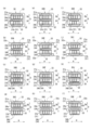
- the spring plate material 30B may be configured as two parts, like the spring plate material 30C in FIG. 15(d).
- the band-shaped spring attachment portion 32a is disposed on the rear side Db relative to the connecting arm spring 31b.
- This spring plate material 30C not only has the same effect as the spring plate material 30 described above, but can also have the same effect as the spring plate material 30A and the spring plate material 30B described above.
- spring plate materials 30D to 30G according to other embodiments will be described with reference to Figs. 15(e) to 15(h).
- the above-mentioned spring plate materials 30, 30A to 30C are configured to be two-part, or to have different extending directions of the opening side arm spring 31a and the connecting side arm spring 31b, but in all cases, the opening side arm spring 31a and the connecting side arm spring 31b, which have contact portions 34 provided at predetermined positions, are arranged offset in the height direction H, so that the opening side contact portion 34a of the opening side arm spring 31a and the connecting side contact portion 34b of the connecting side arm spring 31b are offset in the height direction H, in other words, the opening side contact portion 34a of the opening side arm spring 31a and the connecting side contact portion 34b of the connecting side arm spring 31b are arranged at different positions in the height direction H.
- the opening side arm spring 31a and the connecting side arm spring 31b are not misaligned in the height direction H, that is, the opening side arm spring 31a and the connecting side arm spring 31b are arranged along the depth direction D.
- the position of the opening side contact portion 34a in each opening side arm spring 31a is offset from the position of the connecting side contact portion 34b in the connecting side arm spring 31b.
- the opening side contact portion 34a of the opening side arm spring 31a in the spring plate materials 30D to 30G is positioned on one side in the height direction H (the left side in FIG. 15) about half the length of the contact portion 34 in the height direction H of the contact portion 34 of the arm spring 31 of the spring plate materials 30, 30A to 30C shown in FIG. 15(a) to FIG. 15(d).
- the connecting side contact portion 34b of the connecting side arm spring 31b in the spring plate materials 30D to 30G is disposed on the other side in the height direction H (the right side in FIG. 15) and approximately half the length of the contact portion 34 in the height direction H from the contact portion 34 of the arm spring 31 in the spring plate materials 30, 30A to 30C.
- spring plate materials 30H to 30K according to further embodiments will be described with reference to Figs. 15(i) to 15(l).
- the spring plate materials 30, 30A to 30C are configured such that the opening-side arm spring 31a and the connecting-side arm spring 31b, each having a contact portion 34 provided at a predetermined position, are shifted in the height direction H, so that the opening-side contact portion 34a of the opening-side arm spring 31a and the connecting-side contact portion 34b of the connecting-side arm spring 31b are shifted in the height direction H.
- the same number of opening-side arm springs 31a and connecting-side arm springs 31b are provided.
- the spring plate materials 30H to 30K shown in Figures 15(i) to 15(l) have the same position of the contact portion 34 in the arm spring 31, but the number of opening side arm springs 31a and the number of connecting side arm springs 31b are changed.
- the opening side arm springs 31a in the spring plate materials 30H to 30K are provided with five springs, the same as the opening side arm springs 31a in the spring plate materials 30, 30A to 30G, whereas the connecting side arm springs 31b are provided with four springs, which is fewer than the opening side arm springs 31a.
- the connecting side arm springs 31b which are fewer than the arm springs 31, are disposed at positions corresponding to the spaces between the five opening side arm springs 31a aligned in the height direction H.
- the opening side arm spring 31a and the connecting side arm spring 31b are positioned with an offset in the height direction H, i.e., the opening side arm spring 31a and the connecting side arm spring 31b are positioned at different positions in the height direction H.
- the opening side contact portion 34a of the opening side arm spring 31a and the connecting side contact portion 34b of the connecting side arm spring 31b are positioned with an offset in the height direction H, i.e., the opening side contact portion 34a of the opening side arm spring 31a and the connecting side contact portion 34b of the connecting side arm spring 31b are positioned at different positions in the height direction H.
- the spring plate materials 30H to 30K can achieve the same effects as those achieved by the above-mentioned spring plate materials 30, 30A to 30C. Furthermore, each of the spring plates 30H to 30K that provide the above-described effects can provide the same effects as the relationship of the spring plates 30A to 30C to the spring plate 30.
- the number of connecting side arm springs 31b is set to be less than the number of opening side arm springs 31a, but the number of connecting side arm springs 31b may be set to be greater than the number of opening side arm springs 31a. Furthermore, the difference in number between the opening side arm springs 31a and the connecting side arm springs 31b is not limited to one as described above, and may be configured with an appropriate difference in number.
- the electric wire of the present invention corresponds to the high-voltage electric wire 201
- the terminal body corresponds to the terminal body 210
- the spring member corresponds to the spring plate 30.
- the male terminal corresponds to the male terminal 11
- the insertion space corresponds to the insertion space S
- the side wall corresponds to the side wall 213;
- the arm spring corresponds to the arm spring 31.
- the insertion direction corresponds to the depth direction D.
- the opposing direction corresponds to the width direction W
- the orthogonal direction corresponds to the height direction H
- the contact portion corresponds to the contact portion 34
- the female terminal corresponds to the female terminal 21
- the base end side corresponds to the front side Df
- the tip side corresponds to the back side Db
- the connector housing corresponds to the housing shell 23
- the connector corresponds to the harness side connector 20
- the terminal-equipped electric wire corresponds to the terminal-equipped harness 204
- the connector-attached electric wire corresponds to the connector-attached electric wire 20a
- the wire harness corresponds to wire harness 200.
- the connecting base end corresponds to the lower connecting portion 214
- this invention is not limited to the configuration of the above-mentioned embodiment, but can be applied based on the technical ideas shown in the claims, and many embodiments can be obtained.
- the spring plate materials 30, 30A-30K are attached to both inner surfaces of the side walls 213 facing each other in the width direction W, but the spring plate materials 30, 30A-30K may be provided on only the inner surface of one of the side walls 213.
- the attachment state of the contact portion 34 is managed by the distance between the inner surface of the side wall 213 on which the spring plate materials 30, 30A-30K are not provided and the contact portion 34 (34a, 34b).
- the contact portions 34 (34a, 34b) of the arm springs 31 (31a, 31b) of the spring plate materials 30, 30A to 30K provided on both inner surfaces of the side walls 213 facing each other in the width direction W are configured to face each other in the width direction W without being misaligned in the height direction H, but the contact portions 34 (34a, 34b) of the arm springs 31 (31a, 31b) may be configured to be misaligned in the height direction H.
- the position in the height direction H of the arm spring 31 having the contact portion 34 at a predetermined position is shifted, and the positions in the height direction H of the opening side contact portion 34a of the opening side arm spring 31a and the connecting side contact portion 34b of the connecting side arm spring 31b are shifted.
- the positions in the height direction H of the opening side arm spring 31a and the connecting side arm spring 31b are not shifted, but the positions in the height direction H of the contact portion 34 in each arm spring 31 are shifted, thereby shifting the positions in the height direction H of the opening side contact portion 34a of the opening side arm spring 31a and the connecting side contact portion 34b of the connecting side arm spring 31b.
- the height direction H position of the opening side contact portion 34a in the opening side arm spring 31a and the height direction H position of the connecting side contact portion 34b in the connecting side arm spring 31b may be offset, and the height direction H positions of the opening side arm spring 31a and the connecting side arm spring 31b may be offset.
- the same configuration as the spring plate material 30 described above can be achieved, and since the arm springs 31 (31a, 31b) arranged in multiple positions in the depth direction D and the contact portions 34 (34a, 34b) provided on the arm springs 31 (31a, 31b) are arranged offset from each other in the height direction H, the contact portions 34 (34a, 34b) on the arm springs 31 (31a, 31b) arranged in multiple positions in the depth direction D can be reliably arranged offset from each other in the height direction H.
- the number of contact portions 34 in the arm spring 31 is not limited to the above number, and may be any appropriate number.
- the spring plate material 30 is fixed to the inner surface of the side wall 213 by the welded portion 33, but the fixing method is not limited to the above-described method, and any appropriate method may be used for fixing.
- the pillar portion 148 of the extension body 147 is formed to be thicker than the plate-shaped connection portion 111, but the thickness of the pillar portion 148 may be formed to be approximately the same as the thickness of the plate-shaped connection portion 111.
Landscapes
- Details Of Connecting Devices For Male And Female Coupling (AREA)
Priority Applications (4)
| Application Number | Priority Date | Filing Date | Title |
|---|---|---|---|
| CN202480025895.6A CN121128038A (zh) | 2023-05-19 | 2024-04-19 | 阴型端子、连接器、带端子的电线、带连接器的电线以及线束 |
| JP2025521882A JPWO2024241785A1 (https=) | 2023-05-19 | 2024-04-19 | |
| EP24810793.0A EP4708583A1 (en) | 2023-05-19 | 2024-04-19 | Female terminal, connector, electric wire with terminal, electric wire with connector, and wire harness |
| US19/389,739 US20260074456A1 (en) | 2023-05-19 | 2025-11-14 | Female terminal, connector, terminal-attached electric wire, connector-attached electric wire, and wire harness |
Applications Claiming Priority (2)
| Application Number | Priority Date | Filing Date | Title |
|---|---|---|---|
| JP2023082680 | 2023-05-19 | ||
| JP2023-082680 | 2023-05-19 |
Related Child Applications (1)
| Application Number | Title | Priority Date | Filing Date |
|---|---|---|---|
| US19/389,739 Continuation US20260074456A1 (en) | 2023-05-19 | 2025-11-14 | Female terminal, connector, terminal-attached electric wire, connector-attached electric wire, and wire harness |
Publications (1)
| Publication Number | Publication Date |
|---|---|
| WO2024241785A1 true WO2024241785A1 (ja) | 2024-11-28 |
Family
ID=93589956
Family Applications (1)
| Application Number | Title | Priority Date | Filing Date |
|---|---|---|---|
| PCT/JP2024/015513 Ceased WO2024241785A1 (ja) | 2023-05-19 | 2024-04-19 | メス型端子、コネクタ、端子付き電線、コネクタ付き電線及びワイヤーハーネス |
Country Status (5)
| Country | Link |
|---|---|
| US (1) | US20260074456A1 (https=) |
| EP (1) | EP4708583A1 (https=) |
| JP (1) | JPWO2024241785A1 (https=) |
| CN (1) | CN121128038A (https=) |
| WO (1) | WO2024241785A1 (https=) |
Citations (4)
| Publication number | Priority date | Publication date | Assignee | Title |
|---|---|---|---|---|
| JPS5697888U (https=) * | 1979-12-27 | 1981-08-03 | ||
| JP2019527460A (ja) * | 2016-08-01 | 2019-09-26 | ティーイー・コネクティビティ・コーポレイションTE Connectivity Corporation | 電気コネクタ用の電力端子 |
| JP2022182971A (ja) * | 2021-05-26 | 2022-12-08 | 宣城立訊精密工業有限公司 | 電気接続組立体および電気コネクタ |
| JP2023018355A (ja) | 2021-07-27 | 2023-02-08 | 古河電気工業株式会社 | メス型端子、コネクタ、端子付き電線、コネクタ付き電線及びワイヤーハーネス |
-
2024
- 2024-04-19 WO PCT/JP2024/015513 patent/WO2024241785A1/ja not_active Ceased
- 2024-04-19 CN CN202480025895.6A patent/CN121128038A/zh active Pending
- 2024-04-19 JP JP2025521882A patent/JPWO2024241785A1/ja active Pending
- 2024-04-19 EP EP24810793.0A patent/EP4708583A1/en active Pending
-
2025
- 2025-11-14 US US19/389,739 patent/US20260074456A1/en active Pending
Patent Citations (4)
| Publication number | Priority date | Publication date | Assignee | Title |
|---|---|---|---|---|
| JPS5697888U (https=) * | 1979-12-27 | 1981-08-03 | ||
| JP2019527460A (ja) * | 2016-08-01 | 2019-09-26 | ティーイー・コネクティビティ・コーポレイションTE Connectivity Corporation | 電気コネクタ用の電力端子 |
| JP2022182971A (ja) * | 2021-05-26 | 2022-12-08 | 宣城立訊精密工業有限公司 | 電気接続組立体および電気コネクタ |
| JP2023018355A (ja) | 2021-07-27 | 2023-02-08 | 古河電気工業株式会社 | メス型端子、コネクタ、端子付き電線、コネクタ付き電線及びワイヤーハーネス |
Also Published As
| Publication number | Publication date |
|---|---|
| JPWO2024241785A1 (https=) | 2024-11-28 |
| CN121128038A (zh) | 2025-12-12 |
| EP4708583A1 (en) | 2026-03-11 |
| US20260074456A1 (en) | 2026-03-12 |
Similar Documents
| Publication | Publication Date | Title |
|---|---|---|
| US6224428B1 (en) | Electrical connector and method of assembling and connecting the same with circuit devices | |
| CN102282732B (zh) | 接地用连接器及包含该接地用连接器的线束 | |
| JP4895213B2 (ja) | 電気コネクタ及び電気コネクタ組立体 | |
| CA2636768C (en) | Voltage detection connector for a fuel cell and a fuel cell adapted for same | |
| US9039463B2 (en) | Connector and wire harness | |
| US7479046B2 (en) | Fuel cell and fuel cell connecter | |
| US10819071B2 (en) | Connector structure that is reconfigurable to accommodate either an STP cable or a UTP cable | |
| US12308546B2 (en) | Connector for a flat flexible cable | |
| JP2023005221A (ja) | シールドコネクタ | |
| US20250079767A1 (en) | Hybrid connector and connection structure of hybrid connectors including the same | |
| WO2024241785A1 (ja) | メス型端子、コネクタ、端子付き電線、コネクタ付き電線及びワイヤーハーネス | |
| US20240305047A1 (en) | Electrical connector | |
| JPWO2024241785A5 (https=) | ||
| JP6984492B2 (ja) | コネクタ及びワイヤハーネス | |
| JPH06215831A (ja) | コネクタ構造 | |
| WO2010119905A1 (ja) | コネクタ | |
| JP2005216851A (ja) | メインヘッドランプのランプホルダへの電気接続のための接続要素 | |
| JP2024156268A (ja) | コネクタ及びコネクタ接続構造 | |
| JP7732873B2 (ja) | コネクタ及びコネクタ付き電線 | |
| JP7811361B2 (ja) | コネクタ | |
| US20260128544A1 (en) | Connector and connector manufacturing method | |
| CN113875096B (zh) | 连接器 | |
| JP2024039475A (ja) | コネクタ及びコネクタ接続構造 | |
| JPH0141179Y2 (https=) | ||
| JP2022010651A (ja) | 電線保持構造 |
Legal Events
| Date | Code | Title | Description |
|---|---|---|---|
| 121 | Ep: the epo has been informed by wipo that ep was designated in this application |
Ref document number: 24810793 Country of ref document: EP Kind code of ref document: A1 |
|
| ENP | Entry into the national phase |
Ref document number: 2025521882 Country of ref document: JP Kind code of ref document: A |
|
| WWE | Wipo information: entry into national phase |
Ref document number: 2024810793 Country of ref document: EP |
|
| ENP | Entry into the national phase |
Ref document number: 2024810793 Country of ref document: EP Effective date: 20251202 |
|
| ENP | Entry into the national phase |
Ref document number: 2024810793 Country of ref document: EP Effective date: 20251202 |
|
| NENP | Non-entry into the national phase |
Ref country code: DE |
|
| ENP | Entry into the national phase |
Ref document number: 2024810793 Country of ref document: EP Effective date: 20251202 |
|
| ENP | Entry into the national phase |
Ref document number: 2024810793 Country of ref document: EP Effective date: 20251202 |
|
| ENP | Entry into the national phase |
Ref document number: 2024810793 Country of ref document: EP Effective date: 20251202 |
|
| ENP | Entry into the national phase |
Ref document number: 2024810793 Country of ref document: EP Effective date: 20251202 |
|
| ENP | Entry into the national phase |
Ref document number: 2024810793 Country of ref document: EP Effective date: 20251202 |
|
| ENP | Entry into the national phase |
Ref document number: 2024810793 Country of ref document: EP Effective date: 20251202 |
|
| ENP | Entry into the national phase |
Ref document number: 2024810793 Country of ref document: EP Effective date: 20251202 |
|
| WWP | Wipo information: published in national office |
Ref document number: 2024810793 Country of ref document: EP |