WO2024241690A1 - 作業分担決定装置、作業分担管理システム、作業分担を決定するためにコンピュータで実行される方法、および、プログラム - Google Patents
作業分担決定装置、作業分担管理システム、作業分担を決定するためにコンピュータで実行される方法、および、プログラム Download PDFInfo
- Publication number
- WO2024241690A1 WO2024241690A1 PCT/JP2024/011393 JP2024011393W WO2024241690A1 WO 2024241690 A1 WO2024241690 A1 WO 2024241690A1 JP 2024011393 W JP2024011393 W JP 2024011393W WO 2024241690 A1 WO2024241690 A1 WO 2024241690A1
- Authority
- WO
- WIPO (PCT)
- Prior art keywords
- worker
- robot
- work
- information
- task
- Prior art date
- Legal status (The legal status is an assumption and is not a legal conclusion. Google has not performed a legal analysis and makes no representation as to the accuracy of the status listed.)
- Ceased
Links
Images







Classifications
-
- G—PHYSICS
- G05—CONTROLLING; REGULATING
- G05B—CONTROL OR REGULATING SYSTEMS IN GENERAL; FUNCTIONAL ELEMENTS OF SUCH SYSTEMS; MONITORING OR TESTING ARRANGEMENTS FOR SUCH SYSTEMS OR ELEMENTS
- G05B19/00—Program-control systems
- G05B19/02—Program-control systems electric
- G05B19/418—Total factory control, i.e. centrally controlling a plurality of machines, e.g. direct or distributed numerical control [DNC], flexible manufacturing systems [FMS], integrated manufacturing systems [IMS] or computer integrated manufacturing [CIM]
Definitions
- This disclosure relates to a work sharing device and work sharing system that divides work on a production line between workers and robots.
- Patent Document 1 discloses "a production system and a production method capable of suppressing declines in productivity even when producing multiple types of products" (see [Problem] in [Abstract]).
- the production system 1 according to the embodiment comprises: a plurality of work robots 11-14 that perform tasks assigned to a workpiece 100; a transport robot 15 that transports the workpiece 100 between the plurality of work robots 11-14; and control units 15a, 22 that control the transport operation of the transport robot 15.
- the control units 15a, 22 change the transport procedure performed by the transport robot 15 depending on the type of workpiece 100" (see [Solution] in [Abstract]).
- a transport robot transports all parts. If all transport work is performed solely by the transport robot, it takes time to introduce the transport robot, and so the time required from introduction of the automated transport system to production start-up is longer than the time required for a system in which the transport robot is only partially introduced. Therefore, there is a need for technology that shortens the time required from introduction of the automated transport system to production start-up.
- the present disclosure has been made in consideration of the above-mentioned background.
- One objective according to a certain aspect is to provide technology for sharing transportation work between humans and robots before an automated transportation system is introduced.
- Another objective is to provide technology for supporting the gradual introduction of an automated transportation system.
- a work allocation determination device includes an acquisition means for acquiring information about a device on which work is performed by a robot or a worker, location information about the worker, and operation information about the robot, and a determination means for determining the allocation of work by the robot and the worker based on the information about the device, location information about the worker, and operation information about the robot.
- the determination means uses the information about the device, location information about the worker, and operation information about the robot to calculate a numerical value indicating the ease of access to the device for each of the robot and the worker, identifies the worker or robot for which the best numerical value for ease of access has been calculated, and transmits a work instruction to either the identified worker or robot.
- a work allocation management system includes the work allocation determination device described above, a storage device for storing work instructions, and a management device communicatively connected to the storage device and accepting input from outside.
- the management device accepts input of new work instructions to replace the old work instructions, stores the new work instructions in the storage device, and the determination means transmits the new work instructions to either a worker or a robot.
- a computer-implemented method for determining work allocation includes a step in which a computer processor reads out information of a device on which work is to be performed by a robot or a worker, location information of the worker, and operation information of the robot, and a step in which the processor determines the allocation of work by the robot and the worker based on the information of the device, location information of the worker, and operation information of the robot.
- the determining step includes a step of calculating a numerical value indicating the accessibility of the device for each of the robot and the worker using the information of the device, location information of the worker, and operation information of the robot, a step of identifying the worker or robot for which the numerical value for accessibility has been calculated that is the best, and a step of sending a work instruction to either the identified worker or robot.
- a program for causing a computer to execute the above method is provided.
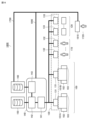
- FIG. 1 is a diagram showing a schematic configuration of a production system 10.
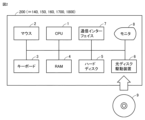
- FIG. 2 is a block diagram showing the hardware configuration of a computer 200 functioning as a work instructing device 140.
- 2 is a diagram showing an outline of the configuration of a transport robot 120.
- FIG. FIG. 2 is a diagram illustrating a schematic configuration of a loading mechanism 102.
- 2 is a diagram showing a schematic configuration of an unloading mechanism 103.
- FIG. 10 is a flowchart showing a part of a process performed by a loading mechanism 102 or an operator 110 to transport a workpiece.
- 10 is a flowchart showing a part of the processing performed in an unloading mechanism 103.
- FIG. 10 is a flowchart showing a part of the processing performed in an unloading mechanism 103.
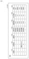
- FIG. 13 is a diagram conceptually showing one mode of data storage in a hard disk 5 that realizes an activity master storage unit 150 according to an embodiment.
- FIG. 13 is a diagram conceptually showing one mode of data storage in hard disk 5 realizing instruction information management unit 160 according to an embodiment.
- 11 is a diagram showing one mode of data storage in a hard disk 5 of a work instructing device 140.
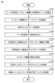
- FIG. 2 is a flowchart showing a part of the process executed by the system 10.
- FIG. 11 is a diagram conceptually showing one mode of data storage in hard disk 5 of computer 200 functioning as work instructing device 140 according to the second embodiment.
- 13 is a flowchart showing a part of a process executed by a computer 200 functioning as a work instructing device 140 according to the second embodiment.
- FIG. 13 is a diagram conceptually showing one mode of data storage in hard disk 5 of computer 200 functioning as work instructing device 140 according to the third embodiment.
- FIG. 13 is a diagram conceptually showing one mode of data storage in a hard disk 5 functioning as an activity master storage unit 150 according to a third embodiment.
- 13 is a flowchart showing a part of a process executed by a computer 200 functioning as a work instructing device 140 according to the third embodiment.
- FIG. 17 shows an outline of the configuration of a system 1700 according to a fourth embodiment.
- FIG. 18 shows an outline of the configuration of a system 1800 according to a fifth embodiment.
- FIG. 18 is a diagram conceptually showing one mode of data storage in hard disk 5 of computer 200 functioning as management device 1810 according to the fifth embodiment.
- 23 is a diagram conceptually showing one mode of data storage in hard disk 5 of computer 200 functioning as work instructing device 140 according to a sixth embodiment.
- 23 is a flowchart showing a part of a process executed by a computer 200 functioning as a work instructing device 140 according to a sixth embodiment.
- FIG. 13 is a diagram conceptually showing one mode of data storage in hard disk 5 of computer 200 functioning as task master storage unit 150 according to the present embodiment.
- 23 is a flowchart illustrating a part of a process executed by a system 10 according to a seventh embodiment.
- FIG. 1 is a diagram showing a schematic overview of the configuration of system 10.
- the system 10 includes one or more production lines 100.
- the production line 100 includes devices 101A and 101B (collectively referred to as device 101), a loading mechanism 102 and an unloading mechanism 103 installed in each device 101, a transport robot 120, a control unit mounted on the transport robot 120 for controlling the transport robot 120, a work instruction device 140, a work master storage unit 150, and an instruction information management unit 160.
- a worker 110 can also transport a workpiece.
- the job master storage unit 150 is realized by a hard disk or other non-volatile storage device.
- the job master storage unit 150 holds master data of the worker 110 and the transport robot 120.
- the master data includes, for example, the name, area of responsibility, device of responsibility, and other information of the worker 110, as well as the identification information, location, available operating hours, and other information of the transport robot 120.
- the instruction information management unit 160 holds work instructions created by the work instruction device 140.
- the work instructions include instructions for transport work to be performed by the worker 110 or the transport robot 120.
- the work instructions may include, for example, identification information for the device 101 that is the target of the transport work, and the scheduled start time and scheduled end time of the transport work.
- the work instruction device 140 is connected to the management system 130 so as to be able to communicate with it.
- the communication format may be either wired or wireless. There are no particular limitations on the communication method.
- the work instruction device 140 includes an instruction unit 141, a determination unit 142, and an output unit 143.
- the instruction unit 141 communicates with each of the management device 131, the wearable terminal 132, and the control unit 133.
- the instruction unit 141 transmits work instructions to the management device 131, the wearable terminal 132, and the control unit 133. In another aspect, the instruction unit 141 receives operation information of the device 101, the work status of the worker 110, and the operation status of the transport robot 120 from the management device 131, the wearable terminal 132, and the control unit 133, respectively.
- the determination unit 142 determines whether the transport task should be performed by the worker 110 or the transport robot 120, based on the information on the device 101, the worker, and the transport robot 120 stored in the task master storage unit 150, as well as the operation information on the device 101, the work status of the worker 110, and the operation status of the transport robot 120.
- the determination unit 142 transmits a task instruction based on the determination to the worker 110 or the transport robot 120 via the instruction unit 141.
- the output unit 143 outputs the contents of the work instructions determined by the determination unit 142 to the instruction information management unit 160.
- the instruction information management unit 160 stores the contents of the work instructions.
- the management system 130 receives commands from the work instruction device 140.
- the management system 130 transmits commands to other devices that are communicatively connected, acquires information from the other devices, and displays the acquired information.
- the management system 130 may include a management device 131, a wearable terminal 132, and a control unit 133.
- the management device 131 is communicatively connected to the device 101 and the work instruction device 140.
- the management device 131 transmits commands to each device including the device 101, the load mechanism 102, and the unload mechanism, and acquires information about the device.
- the acquired information includes, for example, the operation status of the device 101 (operation, normal stop, abnormal stop, and other operating conditions), the content of the work instructed as the work that the device 101 should perform, and the number or number of times processing was performed normally, but the acquired information is not limited to these exemplified pieces of information, and other information may also be acquired.
- the management device 131 acquires information about each device, including the load mechanism 102 and the unload mechanism 103, and displays the acquired information.
- the wearable terminal 132 is worn by each worker 110.
- the wearable terminal 132 is a wristwatch-type terminal with a monitor, receives information from the work instruction device 140, and displays the information on the monitor.
- the wearable terminal 132 may be a head-mounted device, a glasses-type device, a power suit, or the like.
- the wearable terminal 132 has a GPS (Global Positioning System) module, an indoor position identifier, or other position identification circuit.
- the wearable terminal 132 acquires position information of the worker wearing it, and transmits the acquired position information to the management system 130.
- the wearable terminal 132 may accept information input by the worker and transmit the information to the work instruction device 140.
- the control unit 133 is mounted on the transport robot.
- the control unit 133 acquires position information of the transport robot.
- the position information may be either position information identified by a GPS signal, or position information based on a displacement from a preset reference position in the area where the transport robot is used.
- a configuration may be adopted in which a signal transmitter provided at a location in the area where positional information has been specified in advance emits a signal including the position, a transport robot receives the signal, and a wearable terminal 132 receives the signal.
- the management device 131 or the work instruction device 140 can identify the position of the transport robot.
- the wearable terminal 132 receives the signal and transmits the positional information included in the received signal to the management device 131 or the work instruction device 140
- the management device 131 or the work instruction device 140 can identify the position of the wearable terminal 132.
- the work instructing device 140 is realized, for example, as a computer having a known configuration.
- the wearable terminal 132 is communicatively connected to the work instructing device 140 and transmits position information of the worker 110 to the work instructing device 140.
- the wearable terminal receives a work instruction from the work instructing device 140 and notifies the worker 110 of the fact that the work instruction has been received and the contents of the work instruction.
- the transport robot 120 is equipped with a control unit 133 for controlling the transport robot 120.
- the control unit 133 is communicatively connected to a work instruction device 140 and transmits position information of the transport robot 120 to the work instruction device 140.
- the control unit receives a work instruction from the work instruction device 140 and notifies the worker 110 that the work instruction has been received and the contents of the work instruction. Details of the transport robot 120 will be described later ( Figure 3).
- Production line 100 is, for example, a line for assembling products such as semiconductor products. Production line 100 performs multiple processes on the products.
- the device 101 is capable of handling at least one process. Each of the multiple devices is arranged independently for each process. Workpieces that have completed processing in the previous process are transported to the next process. The transport is achieved either by a transport robot 120 or by a worker 110.
- the production line 100 is equipped with a loading mechanism 102 and an unloading mechanism 103 to enable these two to work together.
- the loading mechanism 102 and the unloading mechanism 103 will be described in detail later ( Figures 3 and 4).
- Fig. 2 is a block diagram showing the hardware configuration of a computer 200 that functions as the work instructing device 140.
- Computer 200 mainly comprises the following components: a CPU (Central Processing Unit) 1 that executes programs, a mouse 2 and keyboard 3 that receive instructions input by the user of computer 200, a RAM 4 that volatilely stores data generated by the execution of programs by CPU 1 or data input via mouse 2 or keyboard 3, a hard disk 5 that non-volatilely stores data, an optical disk drive 6, a communications interface (I/F) 7, and a monitor 8. Each component is mutually connected by a data bus.
- a CD-ROM (Compact Disc-Read Only Memory) 9 or other optical disks are loaded into the optical disk drive 6.
- the processing in computer 200 is realized by the various pieces of hardware and software executed by CPU 1.
- Such software may be pre-stored on hard disk 5.
- the software is stored on CD-ROM 9 or other recording medium and distributed as a computer program.
- the software may be provided as a downloadable application program by an information provider connected to the Internet.
- Such software is read from the recording medium by optical disk drive 6 or other reading device, or downloaded via communication interface 7, and then temporarily stored on hard disk 5.
- the software is read from hard disk 5 by CPU 1 and stored in RAM 4 in the form of an executable program.
- CPU 1 executes the program.
- the components constituting computer 200 shown in FIG. 2 are general. Therefore, one of the essential parts of the technical idea of this disclosure can be said to be software stored in RAM 4, hard disk 5, CD-ROM 9 or other recording medium, or software that can be downloaded via a network.
- the recording medium may include a non-transitory computer-readable data recording medium. The operation of each piece of hardware in computer 200 is well known, so a detailed description will not be repeated.
- Recording media are not limited to CD-ROMs, FDs (Flexible Disks), and hard disks, but may also include media that carry programs in a fixed manner, such as SSDs (Solid State Drives), magnetic tapes, optical disks (MOs (Magnetic Optical Discs)/MDs (Mini Discs)/DVDs (Digital Versatile Discs)), IC (Integrated Circuit) cards (including memory cards), optical cards, mask ROMs, EPROMs (Electronically Programmable Read-Only Memory), EEPROMs (Electronically Erasable Programmable Read-Only Memory), flash ROMs, and other semiconductor memories.
- program refers not only to programs that can be executed directly by the CPU, but also to programs in source program format, compressed programs, encrypted programs, etc.
- FIG. 3 is a diagram showing an outline of the configuration of the transport robot 120.
- the transport robot 120 comprises a stage 310, a moving mechanism 320, a control unit 330, a presence sensor 340, a gripping hand 350, and a vision sensor 360.
- the transport robot 120 has two axes, and can control the attitude of the gripping hand 350 with each axis as the center of rotation.
- the stage 310 contains the workpiece to be transported.
- the moving mechanism 320 moves the transport robot 120 to a range that the gripping hand 350 can reach.
- the control unit 330 controls the operation of the transport robot 120. The operation includes movement by the moving mechanism 320, gripping or releasing by the gripping hand 350, raising and lowering the gripping hand 350, and rotation of the gripping hand 350.
- the load sensor 340 detects whether or not a workpiece is present on the stage 310.
- the load sensor 340 can be realized, for example, by using an infrared light emitting element and a light receiving element.
- the transport robot 120 grasps the position of the workpiece using the vision sensor 360 and grasps the workpiece with the grasping hand 350.
- the transport robot 120 places the grasped workpiece on the stage 310 and moves within the production line 100 using the moving mechanism 320.
- the presence of the workpiece placed on the stage 310 is detected by the load sensor 340, and an output signal from the load sensor 340 is sent to the control unit 330.
- the control unit 330 transmits information based on the output signal as the work status of the transport robot 120 to the work instruction device 140, and the information is stored in a database.
- Fig. 4 is a diagram showing a schematic configuration of the load mechanism 102.
- the load mechanism 102 includes a positioning mechanism 410, a width-pushing mechanism 420, a claw 430, a load sensor 440, a light curtain 450, a two-dimensional code reader 460, a monitor 470, and a control unit 480.
- the positioning mechanism 410 includes the width-pushing mechanism 420 and the claw 430.
- a workpiece 490 is mounted on the load mechanism 102.
- the positioning mechanism 410 uses the width adjustment mechanism 420 and the claws 430 to place the workpiece in a predetermined position.
- the load sensor 440 detects whether the workpiece is in a predetermined position in the loading mechanism 102.
- the light curtain 450 acts as a safety sensor to detect intrusion into a specified area of the load mechanism 102.
- the specified area is predefined as an area where intrusion is prohibited for the safety of workers.
- the two-dimensional code reader reads the two-dimensional code attached to the workpiece 490 or the container that holds the workpiece 490.
- Monitor 470 displays the details of the work to be performed by worker 110.
- Monitor 470 is realized, for example, by an organic EL (Electro Luminescence) monitor, a liquid crystal monitor, etc.
- organic EL Electro Luminescence
- the control unit 480 communicates with the work instruction device 140 and controls the operation of the load mechanism 102 based on signals received from the work instruction device 140.
- the control unit 480 is realized, for example, by a control device having functions similar to those of the computer 200.
- Fig. 5 is a diagram showing a schematic configuration of the unload mechanism 103.
- the unload mechanism 103 includes a stage 500, a presence sensor 510, a light curtain 520, and a control unit 530.
- the workpiece 490 is present on the stage 500.
- the stage 500 accommodates the workpiece 490 and transports the workpiece 490.
- the stage 500 includes, for example, a belt conveyor (not shown).
- the presence sensor 510 detects that the workpiece 490 is present on the stage 500. For example, the presence sensor 510 detects that the workpiece 490 has been brought onto the stage 500.
- the light curtain 520 acts as a safety sensor to detect intrusion into a specified area of the unloading mechanism 103.
- This specified area is predefined as an area where intrusion is prohibited for the safety of workers.
- the control unit 530 communicates with the work instruction device 140 and controls the operation of the unload mechanism 103 based on a signal received from the work instruction device 140.
- the control unit 480 is realized by, for example, a control device having functions similar to those of the computer 200.
- Fig. 6 is a flow chart showing a part of the process performed by the loading mechanism 102 or the worker 110 to transport the workpiece.
- step S610 the loading mechanism 102 or the worker 110 transports the workpiece to the device 101.
- step S620 the load mechanism 102 or the worker 110 places the workpiece on the stage 310 of the load mechanism 102. At this time, if the light curtain 450 detects the presence of a foreign object, for example, the hand of the worker 110 or the gripping hand 350 of the transport robot 120, inside the load mechanism 102, the control unit 480 stops the operation of the load mechanism 102.
- a foreign object for example, the hand of the worker 110 or the gripping hand 350 of the transport robot 120
- step S630 the load sensor 440 of the loading mechanism 102 detects the workpiece 490 placed on the stage 400.
- step S640 the load mechanism 102 or the worker 110 performs positioning in the x-axis direction using the width adjustment mechanism 420.
- step S650 the loading mechanism 102 or the operator 110 performs positioning in the y-axis direction using the claw 430.
- step S660 the loading mechanism 102 or the worker 110 temporarily stops transporting the workpiece 490 before loading it into the device 101.
- step S670 the loading mechanism 102 or the worker 110 reads the two-dimensional code attached to the workpiece or the two-dimensional code attached to the container that holds the workpiece.
- step S680 the loading mechanism 102 or the worker 110 resumes the temporarily stopped transport and pulls the workpiece into the device 101.
- the presence sensor 440 detects that the workpiece has disappeared from the stage 400.
- step S690 the control unit 480 of the loading mechanism 102 records that the loading operation of transporting the workpiece into the device 101 has been completed.
- Fig. 7 is a flow chart showing a part of the processing performed in the unloading mechanism 103.
- step S710 the device 101 transports the processed workpiece 490 to the unloading mechanism 103.
- step S720 the workpiece 490 is transported to the stage 500 of the unloading mechanism 103.
- step S730 the presence sensor 510 of the unloading mechanism 103 detects the presence of the workpiece 490.
- step S740 the control unit 530 of the unloading mechanism 103 requests the collection of the workpiece 490.
- the control unit 530 transmits a signal requesting the collection to the transport robot 120.
- the control unit 530 transmits the signal to the wearable terminal 132 worn by the worker 110.
- step S750 the transport robot 120 or the worker 110 moves to the unloading mechanism 103.
- step S760 the transport robot 120 inserts the gripping hand 350 through the light curtain 520 to retrieve the workpiece 490.
- the worker 110 inserts his or her hand through the light curtain 520 to retrieve the workpiece 490.
- step S770 the control unit 530 of the unloading mechanism 103 stops the operation of the unloading mechanism 103 based on the signal output from the light curtain 520.
- step S780 the control unit 530 detects that the workpiece 490 has disappeared from the stage 500 based on the signal output from the presence sensor 510, and detects that the workpiece 490 has been retrieved from the unloading mechanism 103.
- step S790 the control unit 530 records that the unloading operation of the workpiece 490 has been completed.
- Fig. 8 is a diagram conceptually showing one mode of data storage in hard disk 5 that realizes task master storage unit 150 according to an embodiment.
- the work master storage unit 150 holds a table 800 that stores master data.
- the table 800 includes equipment names 810, work names 820, and processing times 830.
- the equipment names 810 are the names of each of the multiple pieces of equipment 101 that make up the production line 100.
- the task name 820 represents the task performed by the device identified by the device name. In a given situation, one device 101 can process one or more tasks.
- Processing time 830 indicates the standard work time required to complete the task identified by task name 820.
- the unit of processing time is not particularly limited.
- FIG. 9 is a conceptual diagram showing one mode of data storage in the hard disk 5 that realizes the instruction information management unit 160 according to one embodiment.
- the instruction information management unit 160 stores the information acquired by the work instruction device 140 and the contents of instructions given by the work instruction device 140 in a database.
- the instruction information management unit 160 holds tables 910 and 920 as tables to be held.
- Table 910 includes information about the device.
- Table 920 includes the work status and schedule of the worker and transport robot.
- table 910 includes device name 911, status 912, and scheduled task completion time 913.
- Device name 911 indicates the name of the device 101 performing the task.
- Status 912 indicates the status of the device.
- Scheduled task completion time 913 indicates the scheduled time for the task to be completed.
- Table 920 includes a task ID (Identification) 921, a worker name 922, a device name 923, a task schedule 924, a start time 925, an end time 926, and a status 927.
- the task ID 921 specifies the task to be performed on the device 101.
- the worker name 922 identifies the worker in charge of the task.
- the device name 923 indicates the device 101 (e.g., device 101A or device 101B) that performs the task.
- the task schedule 924 indicates the content of the task scheduled for the device.
- the start time 925 indicates the time when the task was held.
- the end time indicates the time when the task was completed. In a certain situation, if the task has not been completed, the end time 926 includes, instead of a specific time, for example, null or other management information.
- Status 927 indicates whether the task identified by task ID 927 is completed or in progress.
- the instruction information management unit 160 may further store the operation rate, cycle time, production results, and error history of each device 101 from the information in the table 920, and display this information on the monitor 8 of the computer 200 functioning as the work instruction device 140.
- FIG. 10 is a diagram showing one mode of data storage in the hard disk 5 of the work instruction device 140.
- the hard disk 5 of the work instruction device 140 holds a table 1000.
- Table 1000 includes areas 1010 and 1020.
- Area 1010 holds scores.
- Area 1020 holds the time required before arrival at the device 101. For example, if the time is within one minute, one score is assigned. If the time is five minutes or more, five points are assigned. Scores are determined in advance according to the length of the arrival time, and the work instruction device 140 selects a worker or a transport robot as the target of the work instruction depending on the score.
- Fig. 11 is a flowchart showing a part of the processing executed by the system 10.
- a worker 110 and a transfer robot 120 work together on the production line 100.
- the management system 130 acquires information on the worker 110 and the transport robot 120. More specifically, the management system 130 acquires identification information and position information of the user, the worker 110, from the wearable terminal 132. The management system 130 also acquires identification information, status, and position information of the transport robot 120 from the control unit 133 of the transport robot 120.
- step S1120 the management system 130 acquires information about each device 101 from that device.
- the acquired information includes the device's identification information, operating status, and other status information.
- step S1130 the management system 130 transmits the information acquired in steps S1110 and 1120 to the work instruction device 140. More specifically, the position information of the worker 110, the position information of the transport robot 120, and the identification information, operating status, and other information of each device 101 are sent to the work instruction device 140.
- step S1140 the CPU 1 of the computer 200 operating as the work instruction device 140, as the determination unit 142, determines whether the acquired information includes a work request. If the CPU 1 determines that the information includes a work request (YES in step S1140), it switches control to step S1150. If not (NO in step S1140), the CPU 1 returns control to step S1110.
- step S1150 the CPU 1, functioning as the determination unit 142, acquires the times until the worker 110 and the transport robot 120 arrive at the device 101.
- the determination unit 142 calculates the arrival times based on the distance between the positions identified based on the position information acquired from each of the worker 110 and the transport robot 120 and the device 101 for which work is requested.
- step S1160 CPU 1, functioning as determination unit 142, accesses the database of table 1000 and calculates the score of each candidate that can be the target of instruction based on a predetermined evaluation point system.
- a is a weight.
- the CPU 1 determines the worker or transport robot with the smallest score among the scores obtained by the calculation to be the target of the work instruction.
- step S1170 the CPU 1, as the instruction unit 141, sends a work instruction to the candidate determined as the target of the work instruction, i.e., the worker 110 or the transport robot 120 with the lowest calculated evaluation score.
- step S1180 the CPU 1, as the output unit 143, outputs the work instruction history to the database of the instruction information management unit 160 (table 910).
- step S1190 the CPU 1, functioning as the judgment unit 142, judges whether or not to end the process. If the CPU 1 judges that the process should be ended (YES in step S1190), it ends the control. If not (NO in step S1190), the CPU 1 returns the control to step S1110.
- the management system 130 determines, as the candidate to perform the task, either the worker 110 or the transport robot 120 that takes the shortest time to reach the device 101 that requires the task. This makes it possible to minimize transport wait times on the production line 100.
- System 10 according to the second embodiment differs from system 10 according to the first embodiment in that it determines the target of the work instruction by taking into consideration multiple factors, not limited to the factor of the time required for arrival.
- system according to this embodiment is realized using a hardware configuration similar to that of system 10 according to embodiment 1. Below, the system according to this embodiment will be described using each configuration exemplified in system 10 of embodiment 1.
- the management system determines the target for which the work is to be instructed by taking into consideration factors other than the time until arrival in the evaluation formula for determining the target.
- Fig. 12 is a diagram conceptually showing one mode of data storage in hard disk 5 of computer 200 functioning as work instructing device 140 according to the second embodiment.
- Hard disk 5 includes a table 1200.
- Table 1200 includes score 1210 and work plan 1220.
- Score 1210 is used to derive the score used in the evaluation formula according to this embodiment.
- Work plan 1220 represents a work plan based on the current state of workers 110 and transport robots 120 in production line 100 according to this embodiment. For example, if a certain worker 110 or transport robot 120 does not currently have a work plan, work plan 1220 will be "no plan" and the score will be 1 point.
- the system 10 determines the worker 110 or the transport robot 120 as the target for instructing the work, using the data in table 1200 in addition to the data in table 1000.
- a and b are weights.
- the work instruction device 140 considers two factors, the time until arrival and the work schedule, and determines whether the person to whom instructions for the device 101 requiring work are to be sent is either the worker 110 or the transport robot 120.
- FIG. 13 is a flowchart showing a part of the processing executed by computer 200 functioning as work instructing device 140 according to the second embodiment. Note that the same processes as those described above are denoted by the same reference characters. Therefore, description of the same processes will not be repeated.
- step S1310 the CPU 1, as the determination unit 142, obtains the work schedule of the worker 110 and the transport robot 120 from the table 1200.
- step S1320 the CPU 1, as the judgment unit 142, calculates the score of the instruction candidate based on the time and the work schedule using the above-mentioned formula "time until arrival x a + work schedule x b".
- the judgment unit 142 sends the work instruction to the candidate determined as the target of the work instruction, i.e., the worker 110 or the transport robot 120 with the lowest calculated evaluation score (step S1170), and outputs the history of the work instruction to the database of the instruction information management unit 160 (step S1180).
- the management system 130 determines the target of the work instruction by taking into consideration the current work status and future work schedule of the worker 110 and the transport robot 120. Therefore, the work instruction device 140 can give the optimal work instruction by taking into consideration the overall load status of the worker 110 and the transport robot 120 that are the target of the work instruction.
- Embodiment 3 A third embodiment will be described with reference to Figures 14 to 16.
- the management system according to this embodiment differs from the management system 130 according to the above-described embodiment in that the management system has a function of instructing work taking into account the characteristics of the worker 110 or the transport robot 120.
- the evaluation point method in each of the above-mentioned embodiments employs an algorithm that takes into account the time until the arrival of the worker 110 and the transport robot 120 and the worker load.
- the management system switches the formula for calculating the evaluation value depending on the transportation means, as follows:
- the management system according to this embodiment is realized using a hardware configuration similar to that of the management system 130 according to the first embodiment. Therefore, the description of the hardware configuration will not be repeated. Below, the management system according to this embodiment will be described using each configuration exemplified in the production system 10 that uses the management system 130 of the first embodiment.
- Fig. 14 is a diagram conceptually showing one mode of data storage in hard disk 5 of computer 200 functioning as work instructing device 140 according to the third embodiment.
- Hard disk 5 holds table 1400.
- Table 1400 includes work priority C.
- Work priority C specifies whether a person (e.g., worker 110) or transport robot 120 is to be prioritized as a transport means.
- work instructing device 140 when a user of work instructing device 140, for example, an administrator of system 10, inputs data specifying work priority C to work instructing device 140, work instructing device 140 stores the data in hard disk 5.
- FIG. 15 is a conceptual diagram showing one mode of data storage in the hard disk 5 functioning as the task master storage unit 150.
- the hard disk 5 holds a table 1500.
- table 1500 further includes task priority C.
- the items in table 800 namely, device name 810, task name 820, and processing time 830, are the same as those in embodiment 1, and therefore will not be described again.
- the task priority level C is the content of the table 1400 illustrated in FIG. 14 reflected in the task master storage unit 150.
- the task instruction device 140 accesses the task master storage unit 150, reads the table 1500, and calculates the evaluation value.
- the determination unit 142 determines that the instruction target is the transport robot 120, and calculates the evaluation point using the formula according to the first or second embodiment.
- the determination unit 142 determines that the instruction target is only the worker 110, and calculates the evaluation point using the formula according to the first or second embodiment.
- FIG. 16 is a flowchart showing a part of the processing executed by computer 200 functioning as work instructing device 140. Note that the same processes as those described above are denoted by the same reference characters. Therefore, description of the same processes will not be repeated.
- step S1610 the CPU 1 accesses the task priority C of the worker 110 and the transport robot 120 in the table 1500 read from the task master storage unit 150.
- step S1620 the CPU 1, as the judgment unit 142, calculates the evaluation score of the candidate to be specified using the above formula based on the time, the work schedule, and the work priority C.
- the work instruction device 140 sends a work instruction to the candidate with the lowest score (step S1170) and outputs the work instruction history to the database of the instruction information management unit 160 (step S1180).
- work instructions are sent to the worker 110 or the transport robot 120 taking into consideration the predetermined work priority C. If the work priority C according to the work content is set in advance, more efficient transport can be achieved.
- Fig. 17 is a diagram showing an outline of the configuration of a system 1700 according to the fourth embodiment.
- a manager 1720 of a production line 100 can use a monitoring device 1710 to monitor the state of each device 101 and the working status of a worker 110 and a transport robot 120.
- system according to this embodiment is realized using a hardware configuration similar to that of system 10 according to embodiment 1. Below, the system according to this embodiment will be described using each configuration exemplified in system 10 of embodiment 1.
- system 1700 further includes a monitoring device 1710 in addition to the configuration of system 10.
- Monitoring device 1710 is implemented by computer 200.
- Monitoring device 1710 is communicatively connected to instruction information management unit 160 via network 1790.
- Network 1790 may be either the Internet or an intranet.
- communication may be either wired or wireless, and the communication format is not particularly limited.
- the monitoring device 1710 receives the status of each of the above-mentioned devices 101 and the work status of the worker 110 and the transport robot 120 from the instruction information management unit 160, and displays the received information on the monitor 8.
- the manager 1720 of the production line 100 can easily grasp the operating status of the production line 100 and other information by visually checking the information displayed on the monitor 8.
- the operating status and other information of each device 101, and the position information of the worker 110 or the transport robot 120 are acquired in real time by the monitoring device 1710, and information on the device 101 and data on the working status of the worker 110 or the transport robot 120 are accumulated. This makes it easier to improve the production line 100 and optimize the work rules.
- Fig. 18 is a diagram showing an outline of the configuration of a system 1800 according to the fifth embodiment.
- a manager 1720 of a production line 100 can use a management device 1810 to monitor the state of each device 101 and the working status of an operator 110 and a transport robot 120. Furthermore, the manager 1720 can use the management device 1810 to give working instructions to an operator 110 or a transport robot 120.
- the system 1800 includes a management device 1810 instead of the monitoring device 1710 in the configuration of the system 1700.
- the management device 1810 is realized by the computer 200.
- the management device 1810 is communicatively connected to the work instruction device 140 via a network 1890.
- the network 1890 may be either the Internet or an intranet.
- the communication may be either wired or wireless, and the communication format is not particularly limited.
- the management device 1810 accepts input of instructions by the administrator 1720.
- the instructions include instructions to the worker 110 or the transport robot 120.
- the manager 1720 of the production line 100 can give instructions directly to the workers 110 and the transport robot 120. For example, there may be cases where a work instruction to worker A, who is scheduled to immediately take on a large task due to an emergency, is stopped and an instruction is changed to worker B. In this case, even if worker A is scheduled to take on an emergency event afterwards, since the emergency event is not registered in the instruction information management unit 160, the work instruction device 140 may determine that worker A is not scheduled to take on any work and select worker A as the target of the work instruction. In such a case, it is necessary to cancel the work instruction to worker A, who is confirmed to take on the large task, and give the work instruction to worker B, who is selected as the next candidate based on the evaluation points.
- the administrator 1720 of the system 1800 can use the management device 1810 to cancel the work instruction generated for worker A and give the work instruction to worker B.
- the administrator 1720 can cancel the work instruction generated by the work instruction device 140 or generate a new work instruction that the work instruction device 140 cannot generate, and give the work instruction to the target worker 110 or transport robot 120.
- Fig. 19 is a diagram conceptually showing one mode of data storage in hard disk 5 of computer 200 functioning as management device 1810 according to this embodiment.
- Hard disk 5 includes table 1900.
- Table 1900 includes task ID 1921, worker name 1922, device name 1923, task schedule 1924, start time 1925, end time 1926, and status 1927.
- Task ID 1921 corresponds to task ID 921.
- Worker name 1922 corresponds to worker name 922.
- Equipment name 1923 corresponds to equipment name 923.
- Work plan 1924 corresponds to work plan 924.
- Start time 1925 corresponds to start time 925.
- End time 1926 corresponds to end time 926.
- Status 1927 corresponds to status 927.
- the management device 1810 reads the data of table 900 from the instruction information management unit 160 and expands the read data in RAM 4.
- the manager 1720 can individually specify tasks that the work instructing device 140 cannot schedule, such as emergency interrupt tasks, and other tasks, and create new work instructions.
- the manager 1720 creates work instructions as shown in FIG. 19 while looking at the screen displayed on the monitor 8 of the management device 1810.
- each work instruction is sent to the wearable terminal 132 of the worker 110 and the transport robot 120.
- the table 1900 is stored in the instruction information management unit 160 as the latest database replacing the table 900.
- the flexibility of the operation of the system 1800 can be increased.
- Embodiment 6 A sixth embodiment will be described with reference to Fig. 20 and Fig. 21.
- the work instruction device according to this embodiment differs from the work instruction device 140 according to the above-described embodiment in that the work instruction device can create work instructions while taking into account the load on the worker.
- system according to this embodiment is realized using a hardware configuration similar to that of system 10 according to embodiment 1.
- the same components are given the same reference numerals. Therefore, the description of the same components will not be repeated.
- system according to this embodiment will be described using the components exemplified in system 10 of embodiment 1.
- FIG. 20 is a diagram conceptually showing one mode of data storage in hard disk 5 of computer 200 functioning as work instructing device 140 according to this embodiment.
- Hard disk 5 holds table 2000.
- Table 2000 includes device name 810, work name 820, processing time 830, and workload rate 2010.
- the workload rate 2010 indicates how much load is required of the worker 110 to complete the task.
- the workload rate 2010 is the ratio of the time required to complete the task to the time the worker 110 or the transport robot 120 is available to operate.
- the workload rate 2010 is set in advance by the user of the work instructing device 140 based on the operation information of the worker 110 or the transport robot 120 and the standard time required to complete the task.
- the workload rate 2010 can be updated by the user as appropriate.
- FIG. 21 is a flowchart showing a part of the processing executed by computer 200 functioning as work instructing device 140 according to the sixth embodiment. Note that the same processing as that described above is denoted by the same step numbers. Therefore, description of the same processing will not be repeated.
- step S2110 CPU 1 accesses the master data for the work content of each device and reads out the workload rate for each work content of each device.
- step S2120 the CPU 1 estimates the device on which each worker 110 is working from the position of the worker 110. For example, the CPU 1 determines the device closest to the worker 110 as the position at which the worker 110 is working, based on the position information received from the wearable terminal 132 worn by the worker 110.
- step S2130 the CPU 1 determines the workload rate of each worker 110. For example, the CPU 1 identifies the workload rate of a device determined as the device on which the worker 110 is working based on the master data (step S2110) of the device, and estimates the workload rate of the device as the workload rate of the worker 110.
- step S2140 CPU 1 calculates the score of the candidate for instruction using the times it takes for the worker and robot to arrive at the equipment (step S1150) and the workload rate of the worker (step S2130). As an example, if the workload rate of each worker is below a predetermined upper limit (e.g., 60%), CPU 1 calculates the lowest score for the worker who takes the shortest time to arrive at the equipment. On the other hand, if any of the workload rates exceeds the predetermined upper limit, CPU 1 calculates a score for the candidate for instruction that is, for example, one digit higher, in order to exclude that worker from the candidates.
- a predetermined upper limit e.g. 60%
- step S2150 the CPU 1 transmits the determined work instructions to the wearable terminal 132 worn by the worker 110.
- the work instruction device 140 acquires the location information of each worker 110 from the wearable terminal 132 worn by that worker.
- CPU 1 registers 10% as an example of the workload in the master data. Also, if the status of device A is "product type switching,” CPU 1 registers 60% as an example of the workload.
- the wearable terminal 132 worn by worker X transmits its position information to the work instruction device 140 as the position information of worker X.
- the wearable terminal 132 worn by worker Y transmits its position information to the work instruction device 140 as the position information of worker Y.
- the CPU 1 of the computer 200 functioning as the work instruction device 140 determines that worker X is working on device A, and that worker Y is working on device B. Based on the workload rate 2010 in table 2000, the CPU 1 estimates that the workload rate of worker X is 60% and that of worker Y is 10%.
- CPU 1 can identify either worker X near device A or worker Y near device B as candidates for work instructions.
- the CPU 1 refers to the workload rate of each worker identified as a candidate for a work instruction, and determines whether instructing a new task will cause the workload rate to exceed a predetermined upper limit.
- CPU1 excludes that worker from the workers to whom the new work instruction is to be given, and selects a worker whose workload rate does not exceed the upper limit as a candidate for the work instruction. In this case, if the workload rates of multiple workers do not exceed the upper limit, CPU1 determines the worker with the smallest workload rate as a candidate for the work instruction.
- CPU 1 determines the worker with the smallest workload rate as the candidate for the work instruction.
- the work instruction device 140 transmits work instructions according to the workload rate of each worker, making it easier to equalize the workload rates of each worker. It is also possible to prevent the workload rate of one worker from being significantly higher than the workload rates of other workers.
- Embodiment 7 a seventh embodiment will be described.
- the work instruction device according to this embodiment differs from the work instruction device 140 according to the above-described embodiment in that the work instruction device can create work instructions while taking into consideration production priority.
- the production priority is defined based on which type of product among a plurality of types of products should be produced with priority over other types of products.
- system according to this embodiment is realized using a hardware configuration similar to that of system 10 according to embodiment 1.
- the same components are given the same reference numerals. Therefore, the description of the same components will not be repeated.
- system according to this embodiment will be described using the components exemplified in system 10 of embodiment 1.
- Fig. 22 is a diagram conceptually showing one mode of data storage in hard disk 5 of computer 200 functioning as job master storage unit 150 according to the present embodiment.
- Job master storage unit 150 holds table 2200.
- Table 2200 includes product classification 2210, product name 2220, monthly production plan quantity 2230, and production plan achievement rate 2240.
- the instruction unit 141 of the work instruction device 140 accesses the table 2200 to check the production status of each product.
- the production status includes the monthly production plan number 2230 and the production plan achievement rate 2240 for each product.
- the determination unit 142 derives a production priority for each product and determines the order of production for each product.
- the production priority for each product is calculated as data having a quantity dimension, based on the monthly production plan number 2230 of the product and the production plan achievement rate 2240 of the current month, as shown in the following formula (1).
- ⁇ Production priority level monthly production plan number x (100 - production plan achievement rate) / 100 ... (1)
- the instruction unit 141 outputs an instruction to the device 101 to produce the products in accordance with the production sequence.
- the work instruction device 140 may also have a work master storage unit 150.
- the device 101 e.g., device 101A or device 101B
- receives the instruction outputs the parts request for that product to the work instruction device 140.
- the work instruction device 140 determines the allocation of parts supply work for that product using an evaluation point method. This creates work instructions that take into account the production plan for the product.
- step S2310 the CPU 1 of the computer 200 functioning as the work instruction device 140 accesses the work master storage unit 150 to obtain the monthly production plan number 2230 and the production plan achievement rate 2240.
- step S2320 the CPU 1, as the judgment unit 142, determines the production priority for each product using formula (1).
- step S2330 the CPU 1, functioning as the determination unit 142, determines whether or not the device is outputting a work request. If the CPU 1 determines that the device is outputting a work request (YES in step S2330), it switches control to step S2340. If not (NO in step S2330), the CPU 1 returns control to step S2310.
- step S2340 the CPU 1, as the instruction unit 141, instructs the management system 130 to produce products with high production priority.
- step S2350 the management system 130 calculates the quantity of parts required to produce the specified product and outputs a request for parts according to that quantity.
- step S2360 the system executes the process shown in FIG.
- the system according to the present embodiment calculates the production priority and produces products based on instructions according to the production priority. In this way, the production of multiple products is optimized, and production delays can be suppressed.
Landscapes
- Engineering & Computer Science (AREA)
- General Engineering & Computer Science (AREA)
- Manufacturing & Machinery (AREA)
- Quality & Reliability (AREA)
- Physics & Mathematics (AREA)
- General Physics & Mathematics (AREA)
- Automation & Control Theory (AREA)
- General Factory Administration (AREA)
- Manipulator (AREA)
Priority Applications (2)
| Application Number | Priority Date | Filing Date | Title |
|---|---|---|---|
| JP2025521827A JPWO2024241690A1 (https=) | 2023-05-23 | 2024-03-22 | |
| CN202480032416.3A CN121219654A (zh) | 2023-05-23 | 2024-03-22 | 作业分担决定装置、作业分担管理系统、为了决定作业分担而由计算机执行的方法及程序 |
Applications Claiming Priority (2)
| Application Number | Priority Date | Filing Date | Title |
|---|---|---|---|
| JP2023084637 | 2023-05-23 | ||
| JP2023-084637 | 2023-05-23 |
Publications (1)
| Publication Number | Publication Date |
|---|---|
| WO2024241690A1 true WO2024241690A1 (ja) | 2024-11-28 |
Family
ID=93589943
Family Applications (1)
| Application Number | Title | Priority Date | Filing Date |
|---|---|---|---|
| PCT/JP2024/011393 Ceased WO2024241690A1 (ja) | 2023-05-23 | 2024-03-22 | 作業分担決定装置、作業分担管理システム、作業分担を決定するためにコンピュータで実行される方法、および、プログラム |
Country Status (3)
| Country | Link |
|---|---|
| JP (1) | JPWO2024241690A1 (https=) |
| CN (1) | CN121219654A (https=) |
| WO (1) | WO2024241690A1 (https=) |
Citations (4)
| Publication number | Priority date | Publication date | Assignee | Title |
|---|---|---|---|---|
| JPS57194861A (en) * | 1981-05-25 | 1982-11-30 | Murata Mach Ltd | Automatic transfer system of workpiece in machine shop |
| JP2003345412A (ja) * | 2002-05-24 | 2003-12-05 | Sankyo Seiki Mfg Co Ltd | ワーク搬送システム |
| WO2020217861A1 (ja) * | 2019-04-24 | 2020-10-29 | パナソニックIpマネジメント株式会社 | 製造工場における作業指示装置、および製造工場における作業指示方法 |
| JP2023003723A (ja) * | 2021-06-24 | 2023-01-17 | 三菱電機株式会社 | 作業指示システム、作業指示装置、作業指示方法およびプログラム |
-
2024
- 2024-03-22 WO PCT/JP2024/011393 patent/WO2024241690A1/ja not_active Ceased
- 2024-03-22 CN CN202480032416.3A patent/CN121219654A/zh active Pending
- 2024-03-22 JP JP2025521827A patent/JPWO2024241690A1/ja active Pending
Patent Citations (4)
| Publication number | Priority date | Publication date | Assignee | Title |
|---|---|---|---|---|
| JPS57194861A (en) * | 1981-05-25 | 1982-11-30 | Murata Mach Ltd | Automatic transfer system of workpiece in machine shop |
| JP2003345412A (ja) * | 2002-05-24 | 2003-12-05 | Sankyo Seiki Mfg Co Ltd | ワーク搬送システム |
| WO2020217861A1 (ja) * | 2019-04-24 | 2020-10-29 | パナソニックIpマネジメント株式会社 | 製造工場における作業指示装置、および製造工場における作業指示方法 |
| JP2023003723A (ja) * | 2021-06-24 | 2023-01-17 | 三菱電機株式会社 | 作業指示システム、作業指示装置、作業指示方法およびプログラム |
Also Published As
| Publication number | Publication date |
|---|---|
| JPWO2024241690A1 (https=) | 2024-11-28 |
| CN121219654A (zh) | 2025-12-26 |
Similar Documents
| Publication | Publication Date | Title |
|---|---|---|
| US11164462B2 (en) | Vehicle dispatch instruction device, vehicle dispatch instruction method, and recording medium | |
| WO2018140555A1 (en) | Systems, methods and apparatus for distribution of products and supply chain management | |
| KR102264413B1 (ko) | 사용자에 의한 상품 피킹을 보조하는 방법 및 장치 | |
| CN110582455A (zh) | 自动化仓库履行操作和系统 | |
| JP2022095604A (ja) | 物品の移管を管理する電子装置およびその情報管理方法 | |
| US20220397912A1 (en) | Systems and methods for dynamic routing autonomous vehicles | |
| CN116457140B (zh) | 刀具搬送系统及其控制方法、以及计算机可读存储介质 | |
| JP2020040762A (ja) | 管理装置、ピッキングシステムおよびピッキング管理方法 | |
| KR20250038223A (ko) | 전자 장치 및 그의 정보 관리 방법 | |
| WO2022270162A1 (ja) | 情報処理システム、倉庫の管理方法及び倉庫制御装置 | |
| WO2024241690A1 (ja) | 作業分担決定装置、作業分担管理システム、作業分担を決定するためにコンピュータで実行される方法、および、プログラム | |
| US20230384756A1 (en) | Tool management device | |
| JP2022133799A (ja) | 工具搬送システム、工具搬送システムの制御方法、および工具搬送システムの制御プログラム | |
| JP7826063B2 (ja) | 制御装置、制御方法、プログラム、及び物品搬送システム | |
| JP2022092533A (ja) | 制御装置、プログラム、システム、及び方法 | |
| EP3583569B1 (en) | Vending system and method of automatically vending | |
| KR102245753B1 (ko) | 아이템 수거 정보를 제공하는 전자 장치 및 그 방법 | |
| WO2020100220A1 (ja) | 搬送作業制御装置、システム、方法およびコンピュータ可読媒体 | |
| US20220309442A1 (en) | Server and method | |
| US7010377B2 (en) | Method, system, and storage medium for facilitating a transport scheme in an automated material handling system environment | |
| US20240103922A1 (en) | Design execution apparatus and design execution method | |
| JP7639138B2 (ja) | 加工システム、検索方法、および検索プログラム | |
| JPWO2018189851A1 (ja) | 搬送作業制御装置、システム、方法およびプログラム | |
| US20220004195A1 (en) | Automatic Article Conveying System and Automatic Article Conveying Method | |
| JP7770897B2 (ja) | 情報処理装置、情報処理方法、プログラム及びシステム |
Legal Events
| Date | Code | Title | Description |
|---|---|---|---|
| 121 | Ep: the epo has been informed by wipo that ep was designated in this application |
Ref document number: 24810698 Country of ref document: EP Kind code of ref document: A1 |
|
| ENP | Entry into the national phase |
Ref document number: 2025521827 Country of ref document: JP Kind code of ref document: A |
|
| WWE | Wipo information: entry into national phase |
Ref document number: 2025521827 Country of ref document: JP |
|
| NENP | Non-entry into the national phase |
Ref country code: DE |