WO2024241417A1 - 熱交換器およびこの熱交換器を備えた冷凍サイクル装置 - Google Patents
熱交換器およびこの熱交換器を備えた冷凍サイクル装置 Download PDFInfo
- Publication number
- WO2024241417A1 WO2024241417A1 PCT/JP2023/018916 JP2023018916W WO2024241417A1 WO 2024241417 A1 WO2024241417 A1 WO 2024241417A1 JP 2023018916 W JP2023018916 W JP 2023018916W WO 2024241417 A1 WO2024241417 A1 WO 2024241417A1
- Authority
- WO
- WIPO (PCT)
- Prior art keywords
- heat exchanger
- pair
- flat tubes
- refrigerant flow
- section
- Prior art date
- Legal status (The legal status is an assumption and is not a legal conclusion. Google has not performed a legal analysis and makes no representation as to the accuracy of the status listed.)
- Ceased
Links
Images








Classifications
-
- F—MECHANICAL ENGINEERING; LIGHTING; HEATING; WEAPONS; BLASTING
- F28—HEAT EXCHANGE IN GENERAL
- F28D—HEAT-EXCHANGE APPARATUS, NOT PROVIDED FOR IN ANOTHER SUBCLASS, IN WHICH THE HEAT-EXCHANGE MEDIA DO NOT COME INTO DIRECT CONTACT
- F28D1/00—Heat-exchange apparatus having stationary conduit assemblies for one heat-exchange medium only, the media being in contact with different sides of the conduit wall, in which the other heat-exchange medium is a large body of fluid, e.g. domestic or motor car radiators
- F28D1/02—Heat-exchange apparatus having stationary conduit assemblies for one heat-exchange medium only, the media being in contact with different sides of the conduit wall, in which the other heat-exchange medium is a large body of fluid, e.g. domestic or motor car radiators with heat-exchange conduits immersed in the body of fluid
- F28D1/04—Heat-exchange apparatus having stationary conduit assemblies for one heat-exchange medium only, the media being in contact with different sides of the conduit wall, in which the other heat-exchange medium is a large body of fluid, e.g. domestic or motor car radiators with heat-exchange conduits immersed in the body of fluid with tubular conduits
- F28D1/053—Heat-exchange apparatus having stationary conduit assemblies for one heat-exchange medium only, the media being in contact with different sides of the conduit wall, in which the other heat-exchange medium is a large body of fluid, e.g. domestic or motor car radiators with heat-exchange conduits immersed in the body of fluid with tubular conduits the conduits being straight
- F28D1/0535—Heat-exchange apparatus having stationary conduit assemblies for one heat-exchange medium only, the media being in contact with different sides of the conduit wall, in which the other heat-exchange medium is a large body of fluid, e.g. domestic or motor car radiators with heat-exchange conduits immersed in the body of fluid with tubular conduits the conduits being straight the conduits having a non-circular cross-section
- F28D1/05366—Assemblies of conduits connected to common headers, e.g. core type radiators
- F28D1/05391—Assemblies of conduits connected to common headers, e.g. core type radiators with multiple rows of conduits or with multi-channel conduits combined with a particular flow pattern, e.g. multi-row multi-stage radiators
-
- F—MECHANICAL ENGINEERING; LIGHTING; HEATING; WEAPONS; BLASTING
- F28—HEAT EXCHANGE IN GENERAL
- F28F—DETAILS OF HEAT-EXCHANGE AND HEAT-TRANSFER APPARATUS, OF GENERAL APPLICATION
- F28F9/00—Casings; Header boxes; Auxiliary supports for elements; Auxiliary members within casings
- F28F9/02—Header boxes; End plates
-
- F—MECHANICAL ENGINEERING; LIGHTING; HEATING; WEAPONS; BLASTING
- F25—REFRIGERATION OR COOLING; COMBINED HEATING AND REFRIGERATION SYSTEMS; HEAT PUMP SYSTEMS; MANUFACTURE OR STORAGE OF ICE; LIQUEFACTION SOLIDIFICATION OF GASES
- F25B—REFRIGERATION MACHINES, PLANTS OR SYSTEMS; COMBINED HEATING AND REFRIGERATION SYSTEMS; HEAT PUMP SYSTEMS
- F25B13/00—Compression machines, plants or systems, with reversible cycle
-
- F—MECHANICAL ENGINEERING; LIGHTING; HEATING; WEAPONS; BLASTING
- F25—REFRIGERATION OR COOLING; COMBINED HEATING AND REFRIGERATION SYSTEMS; HEAT PUMP SYSTEMS; MANUFACTURE OR STORAGE OF ICE; LIQUEFACTION SOLIDIFICATION OF GASES
- F25B—REFRIGERATION MACHINES, PLANTS OR SYSTEMS; COMBINED HEATING AND REFRIGERATION SYSTEMS; HEAT PUMP SYSTEMS
- F25B2500/00—Problems to be solved
- F25B2500/01—Geometry problems, e.g. for reducing size
-
- F—MECHANICAL ENGINEERING; LIGHTING; HEATING; WEAPONS; BLASTING
- F25—REFRIGERATION OR COOLING; COMBINED HEATING AND REFRIGERATION SYSTEMS; HEAT PUMP SYSTEMS; MANUFACTURE OR STORAGE OF ICE; LIQUEFACTION SOLIDIFICATION OF GASES
- F25B—REFRIGERATION MACHINES, PLANTS OR SYSTEMS; COMBINED HEATING AND REFRIGERATION SYSTEMS; HEAT PUMP SYSTEMS
- F25B39/00—Evaporators; Condensers
- F25B39/02—Evaporators
-
- F—MECHANICAL ENGINEERING; LIGHTING; HEATING; WEAPONS; BLASTING
- F25—REFRIGERATION OR COOLING; COMBINED HEATING AND REFRIGERATION SYSTEMS; HEAT PUMP SYSTEMS; MANUFACTURE OR STORAGE OF ICE; LIQUEFACTION SOLIDIFICATION OF GASES
- F25B—REFRIGERATION MACHINES, PLANTS OR SYSTEMS; COMBINED HEATING AND REFRIGERATION SYSTEMS; HEAT PUMP SYSTEMS
- F25B39/00—Evaporators; Condensers
- F25B39/04—Condensers
-
- F—MECHANICAL ENGINEERING; LIGHTING; HEATING; WEAPONS; BLASTING
- F28—HEAT EXCHANGE IN GENERAL
- F28D—HEAT-EXCHANGE APPARATUS, NOT PROVIDED FOR IN ANOTHER SUBCLASS, IN WHICH THE HEAT-EXCHANGE MEDIA DO NOT COME INTO DIRECT CONTACT
- F28D21/00—Heat-exchange apparatus not covered by any of the groups F28D1/00 - F28D20/00
- F28D2021/0019—Other heat exchangers for particular applications; Heat exchange systems not otherwise provided for
- F28D2021/0068—Other heat exchangers for particular applications; Heat exchange systems not otherwise provided for for refrigerant cycles
-
- F—MECHANICAL ENGINEERING; LIGHTING; HEATING; WEAPONS; BLASTING
- F28—HEAT EXCHANGE IN GENERAL
- F28F—DETAILS OF HEAT-EXCHANGE AND HEAT-TRANSFER APPARATUS, OF GENERAL APPLICATION
- F28F1/00—Tubular elements; Assemblies of tubular elements
- F28F1/02—Tubular elements of cross-section which is non-circular
- F28F1/022—Tubular elements of cross-section which is non-circular with multiple channels
-
- F—MECHANICAL ENGINEERING; LIGHTING; HEATING; WEAPONS; BLASTING
- F28—HEAT EXCHANGE IN GENERAL
- F28F—DETAILS OF HEAT-EXCHANGE AND HEAT-TRANSFER APPARATUS, OF GENERAL APPLICATION
- F28F9/00—Casings; Header boxes; Auxiliary supports for elements; Auxiliary members within casings
- F28F9/02—Header boxes; End plates
- F28F2009/0285—Other particular headers or end plates
Definitions
- This disclosure relates to a heat exchanger equipped with flat tubes and a refrigeration cycle device equipped with this heat exchanger.
- Patent Document 1 there is a heat exchanger that includes a pair of headers that face each other with a gap between them, and a number of flat tubes that are spaced apart between the pair of headers and have both ends in the tube axis direction connected to the pair of headers (see, for example, Patent Document 1).
- the heat exchanger in Patent Document 1 is configured in an L-shape when viewed in the direction in which the flat tubes extend, and the pair of headers have L-bend portions that are bent into an L-shape.
- the heat exchanger of Patent Document 1 discloses a technique for preventing damage to the brazed portion between the header and the flat tube at the bent portion when a pair of headers are bent into an L shape.
- the outer periphery of both ends of the flat tube in the tube axial direction that connect to the header is made larger than the outer periphery of the other ends, and a large brazing allowance is secured, thereby ensuring the strength of the connection between the L-bend portion of the header and the flat tube and preventing damage.
- the heat exchanger of Patent Document 1 has a configuration in which the outer periphery at both ends of the flat tube in the tube axis direction is larger than the outer periphery at the other ends, and since the outer periphery is not uniform in the tube axis direction, the manufacturing process of the flat tube itself tends to be complicated. For this reason, it is required that the heat exchanger has a configuration in which the outer periphery of the flat tube, in other words the outer shape of the flat tube, is uniform in the tube axis direction while increasing the strength of the connection points.
- One possible method of increasing the strength of the connection points is to increase the thickness of the flat tube to increase its strength.
- the cross-sectional area of the refrigerant flow path formed inside the flat tube must be reduced, which poses the problem of increased pressure loss of the refrigerant.
- the present disclosure is intended to solve the problems described above, and aims to provide a heat exchanger in which a pair of headers have L-shaped bends, which can improve the strength of the flat tubes while suppressing an increase in pressure loss, and a refrigeration cycle device equipped with this heat exchanger.
- the heat exchanger according to the present disclosure is a heat exchanger including a plurality of flat tubes extending in the vertical direction, formed with a flattened outer shape, and having a plurality of refrigerant flow paths formed by through holes, and a pair of headers connected to both ends of the flat tubes in the vertical direction and having an L-shaped bend portion that is L-shaped when viewed from above, each of the flat tubes having a shape with a long axis and a short axis in a vertical cross section perpendicular to the tube axis direction, and among the flat tubes, at least one or more flat tubes connected to the L-shaped bend portion each have a greater wall thickness at both ends in the long axis direction along the long axis in the vertical cross section, and a smaller wall thickness toward the center in the long axis direction.
- the refrigeration cycle device disclosed herein comprises a compressor, a condenser, a pressure reducer, and an evaporator, and at least one of the condenser and the evaporator is configured with the above-mentioned heat exchanger.
- each of the one or more flat tubes connected to at least the L-shaped bend portion has a greater wall thickness at both ends in the long axis direction along the long axis in the vertical cross section, and a smaller wall thickness at the center in the long axis direction.
- One of the ends in the long axis direction along the long axis in the vertical cross section is located on the outside of the bend in the L-shaped bend portion of the pair of headers. Therefore, the heat exchanger and refrigeration cycle device according to the present disclosure can increase the wall thickness of the flat tube on the outside of the bend in the L-shaped bend portion of the pair of headers to increase the strength, and can suppress damage to the flat tube.
- the wall thickness of the center of the flat tube in the long axis direction is thinner than the wall thickness of both ends in the long axis direction, so that the flow path cross-sectional area can be secured and an increase in pressure loss can be suppressed compared to a configuration in which the wall thickness of the center in the long axis direction is as large as the wall thickness of both ends.
- the heat exchanger can suppress an increase in pressure loss while improving the strength of the flat tube.
- FIG. 1 is a schematic perspective view of a heat exchanger according to a first embodiment
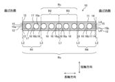
- FIG. 2 is an explanatory diagram showing the configuration of a flat tube of the heat exchanger according to the first embodiment.
- 4 is a schematic perspective view of a connection portion between a flat tube and a header of a heat exchanger according to the first embodiment.
- FIG. 4 is an enlarged plan view of an L-shaped bent portion of a header in the heat exchanger according to the first embodiment.
- FIG. FIG. 4 is an explanatory diagram of the dimensional names of flat tubes of the heat exchanger according to the first embodiment.
- 2 is a cross-sectional view showing the configuration of a flat tube of a heat exchanger according to the first embodiment.
- FIG. 4 is an explanatory diagram of the dimensional names of flat tubes of the heat exchanger according to the first embodiment.
- 13 is a diagram showing a vertical cross section of a flat tube in which an inner pillar is broken in the flat tube of the comparative example.
- FIG. 4A to 4C are explanatory diagrams of a manufacturing process for the heat exchanger according to the first embodiment.
- 11 is a diagram showing a vertical cross section of a flat tube of a heat exchanger according to a second embodiment.
- FIG. 13 is a diagram showing a vertical cross section of a flat tube of a heat exchanger according to embodiment 3.
- FIG. FIG. 4 is an explanatory diagram of drift of liquid refrigerant in a header.
- FIG. 13 is a diagram showing a vertical cross section of a flat tube of a heat exchanger according to embodiment 4.
- FIG. 13 is a diagram showing a vertical cross section of a flat tube of a heat exchanger according to embodiment 5.
- FIG. 13 is a diagram showing a vertical cross section of a flat tube of a heat exchanger according to a sixth embodiment of the present invention.
- FIG. 13 is a graph showing the relationship between the major axis length Tw of the flat tubes, the pitch interval Dp of the flat tubes, and the bendable radius R0 of the L-bend portion in a heat exchanger according to embodiment 7.
- FIG. 13 is a refrigerant circuit diagram showing a schematic configuration of a refrigeration cycle device according to an eighth embodiment.
- FIG. 1 is a schematic perspective view of a heat exchanger 100 according to a first embodiment.
- the up-down direction in Fig. 1 represents the direction of gravity.
- the heat exchanger 100 according to the first embodiment is an air heat exchanger used as a component of a refrigeration cycle device, and performs heat exchange between air and a refrigerant.
- the positional relationship between each component, the extension direction of each component, and the parallel direction of each component are, in principle, those when the heat exchanger 100 is installed in a usable state.
- the heat exchanger 100 has a plurality of flat tubes 10 extending in the vertical direction, a pair of headers 20 arranged at both ends of the extension direction of the plurality of flat tubes 10, and a plurality of corrugated fins 30 arranged between adjacent flat tubes 10.
- the heat exchanger 100 is not limited to a configuration having corrugated fins 30, and may be a finless heat exchanger that does not have corrugated fins 30, or a plate heat exchanger that has a plurality of plate fins through which the plurality of flat tubes 10 penetrate.
- the heat exchanger 100 is formed in an L-shape when viewed vertically, and has a first heat exchange section 101 extending in the left-right direction, a second heat exchange section 102 extending in the front-rear direction, and a third heat exchange section 103 connecting the first heat exchange section 101 and the second heat exchange section 102.
- Each of the first heat exchange section 101, the second heat exchange section 102, and the third heat exchange section 103 has a plurality of flat tubes 10, a portion of a pair of headers 20, and a plurality of corrugated fins 30.
- Each of the flat tubes 10 extends in the vertical direction.
- the flat tubes 10 are arranged in parallel with one another at intervals. Both ends of the flat tubes 10 in the vertical direction (tube axis direction) are inserted into a pair of headers 20 and joined by brazing.
- the header 20 is a cylindrical body with both ends closed, and a space is formed inside through which the refrigerant flows.
- the header 20 has a rectangular cross-sectional shape, but this is not limited to a rectangular shape and may be a circular or elliptical shape, and can be modified as appropriate.
- the structure of the header 20 may be a stack of plate-shaped bodies with slits formed therein, other than the above-mentioned cylindrical body with both ends closed.
- the pair of headers 20 may have different external shapes or cross-sectional shapes.
- One header 20 has an inlet 20a through which the refrigerant flows in, and the other header 20 has an outlet 20b through which the refrigerant flows out.
- the refrigerant that flows into one header 20 from the inlet 20a is distributed to each of the flat tubes 10 and flows through each flat tube 10 from the bottom to the top, then joins together in the other header 20 and flows out from the outlet 20b.
- Each of the pair of headers 20 is formed in an L-shape when viewed in the vertical direction.
- the header 20 has a first straight portion 21 extending in the left-right direction, a second straight portion 22 extending in the front-rear direction, and an L-bend portion 23 connecting the first straight portion 21 and the second straight portion 22.
- FIG. 2 is an explanatory diagram showing the configuration of the flat tube 10 of the heat exchanger 100 according to the first embodiment.
- FIG. 3 is a schematic perspective view of the connection portion between the flat tube 10 and the header 20 of the heat exchanger 100 according to the first embodiment.
- FIG. 4 is an enlarged plan view of the L-bend portion 23 of the header 20 in the heat exchanger 100 according to the first embodiment.
- the outer shape of the flat tube 10 is illustrated by a dotted line to show the positional relationship between the header 20 and the flat tube 10.
- FIG. 5 is an explanatory diagram showing the dimensional names of the flat tube 10 of the heat exchanger 100 according to the first embodiment.
- FIGS. 2 and 5 show a cross section of the flat tube 10 perpendicular to the axial direction of the flat tube 10 (hereinafter referred to as a vertical cross section).
- the flat tube 10 has a cross-sectional shape that is flat in one direction, such as an oval shape.
- the flat tube 10 has a flat outer shape, and has a shape that has a major axis and a minor axis in a vertical cross section.
- the flat tube 10 has a symmetrical structure with respect to a center line L1, which will be described later.
- the flat tube 10 has a pair of long axis sides 11 extending along the long axis direction and a pair of short axis sides 12 extending along the short axis direction.
- the flat tube 10 has a pair of curved portions 13 connecting both ends of one side (left side in FIG. 2) of the pair of long axis sides 11 to both ends of the short axis side 12a of the pair of short axis sides 12.
- the flat tube 10 has a pair of curved portions 14 connecting both ends of the other side (right side in FIG. 2) of the pair of long axis sides 11 to both ends of the short axis side 12b of the pair of short axis sides 12.
- the short axis side 12a is located on the outside of the bend
- the short axis side 12b is located on the inside of the bend.
- the outside of the bend corresponds to the outside of the bend of the L-bend portion 23 of the header 20 as shown in FIG. 3 and FIG. 4
- the inside of the bend corresponds to the inside of the bend of the L-bend portion 23 of the header 20.
- the flat tube 10 is a flat porous tube having multiple refrigerant flow paths 10a formed by through holes.
- the multiple refrigerant flow paths 10a are arranged side by side in the longitudinal direction.
- the cross-sectional shape of the refrigerant flow paths 10a is rectangular, but this is not limited to a rectangular shape and may be other shapes, such as a circular shape.
- R1, R2, R3, and R4 are the four regions obtained by dividing the vertical cross section of the flat tube 10 by the center line L1 and a pair of imaginary center lines L3. Regions R1, R2, R3, and R4 are in this order from the outside of the bend toward the inside of the bend.
- Rc A central region that is an area inside a pair of central virtual lines L3 in a vertical cross section of the flat tube 10.
- Ro Outer end region, which is a region outside a pair of center virtual lines L3 in a vertical cross section of the flat tube 10. In Fig. 4, the light dotted portion corresponds to the central region Rc, and the dark dotted portion corresponds to the outer end region Ro.
- the central region Rc is also a region having regions R2 and R3.
- the outer end region Ro is also a region having regions R1 and R4.
- L1 Center line which is a line passing through the center of the long axis direction of the flat tube 10 in the vertical cross section of the flat tube 10.
- L2 A pair of outer end virtual lines which are a pair of lines passing through both ends of the long axis direction of the flat tube 10 in the vertical cross section of the flat tube 10 and are parallel to the center line L1.
- L3 A pair of center virtual lines which are a pair of lines passing through the center of the center line L1 and each of the pair of outer end virtual lines L2 in the vertical cross section of the flat tube 10.
- L4 A pair of short axis flow path end virtual lines which are a pair of lines passing through both ends of the short axis direction of the multiple refrigerant flow paths 10a in the vertical cross section of the flat tube 10.
- L5 A pair of long axis flow path end virtual lines which are a pair of lines passing through both ends of the long axis direction of the multiple refrigerant flow paths 10a in the vertical cross section of the flat tube 10.
- the flat tube 10 When viewed in vertical cross section, the flat tube 10 has a first outer column 15, an inner column 16, and a second outer column 17, and the dots in FIG. 2 indicate the first outer column 15, the inner column 16, and the second outer column 17 in order from darker to lighter dots.
- the first outer column 15, the inner column 16, and the second outer column 17 are defined as follows:
- First outer column 15 A portion that is on the inside of a pair of short-axis flow path end imaginary lines L4 and on the outside of a pair of long-axis flow path end imaginary lines L5 in a vertical cross section.
- Inner column 16 A portion that is on the inside of a pair of short-axis flow path end imaginary lines L4 in a vertical cross section and between adjacent refrigerant flow paths 10a.
- Second outer column 17 A portion that is on the outside of a pair of short-axis flow path end imaginary lines L4 in a vertical cross section.
- first outer column 15a There are two first outer columns 15, one at each end in the longitudinal direction, and the first outer column 15 located on the outside of the bend may be referred to as first outer column 15a, and the first outer column 15 located on the inside of the bend may be referred to as first outer column 15b.
- Tw Long axis length, which is the length in the long axis direction of the flat tube 10 in a vertical cross section
- Dp Pitch interval of the flat tube 10 in a vertical cross section ⁇ 1 : Long axis thickness of the inner column 16a among the multiple inner columns 16 that is closest to the center line L1 ⁇ 2 : Long axis thickness of the inner column 16b among the multiple inner columns 16 that is farthest from the center line L1 tx : Long axis thickness of the first outer column 15 ty : Short axis thickness of the second outer column 17
- the pitch interval Dp refers to the pitch interval before bending or the pitch interval in parts other than the L-bend portion 23.
- the heat exchanger 100 may have a circular cross section of the refrigerant flow path 10a of the flat tubes 10, but the dimensions when the refrigerant flow path 10a has a circular cross section are as shown in Figures 6 and 7 below.
- FIG. 6 is a cross-sectional view showing the configuration of the flat tube 10 of the heat exchanger 100 according to the first embodiment.
- FIG. 7 is an explanatory diagram of the dimensional names of the flat tube 10 of the heat exchanger 100 according to the first embodiment.
- the flow passage cross section of the refrigerant flow passage 10a is rectangular, the dimensions are approximately the same as when it is circular, and only dimensions that require special explanation are described here.
- ⁇ 1 Among the multiple inner columns 16, the thickness in the long axis direction of the inner column 16a closest to the center line L1, and the thickness at the narrowest part ⁇ 2 : Among the multiple inner columns 16, the thickness in the long axis direction of the inner column 16b farthest from the center line L1, and the thickness at the narrowest part t x : The thickness in the long axis direction of the first outer column 15, and the thickness at the narrowest part t y : The thickness in the short axis direction of the second outer column 17, and the thickness at the narrowest part
- the header 20 has an L-shaped bend 23, so that during manufacturing, a stretching force acts on the flat tubes 10 on the outside of the bend as shown by the arrow a in FIG. 4, and a compressive force acts on the inside of the bend as shown by the arrow b in FIG. 4.
- the directions of the arrows a and b are the minor axis directions.
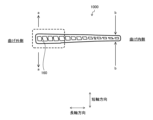
- FIG. 8 is a vertical cross-section of the flat tube 1000 of the comparative example in which the inner column 160 is broken.
- the left side of the figure is the outside of the bend
- the right side of the figure is the inside of the bend.
- a force acts on the outside of the bend that stretches it in the direction of the arrow a (short axis direction), causing the inner column 160 to break, resulting in damage to the flat tube 1000. Also, from FIG.
- the heat exchanger 100 of embodiment 1 has the following structure for the flat tubes 10, which can suppress damage to the flat tubes 10, particularly breakage of the first outer column 15 and the inner column 16.
- the flat tube 10 is formed so that the wall thickness is greater at both ends in the long axis direction in the vertical cross section, and is smaller at the center in the long axis direction.
- both ends in the long axis direction in the vertical cross section are the first outer columns 15, and the wall thickness t x of the first outer columns 15 is greater than ⁇ 1 , which corresponds to the wall thickness of the center in the long axis direction.
- the flat tube 10 has a relationship of t x > ⁇ 1.
- the flat tube 10 has a wall thickness greater at both ends in the long axis direction in the vertical cross section, and is smaller at the center in the long axis direction" only needs to be greater than the wall thickness of the center in the long axis direction in the vertical cross section, and includes a configuration in which there are parts with the same wall thickness between both ends in the long axis direction in the vertical cross section and the center in the long axis direction.
- the flat tube 10 may be formed so that the wall thickness is greater at both ends in the longitudinal direction in a vertical cross section and is smaller toward the center in the longitudinal direction. For this reason, the flat tube 10 has at least one of the following configurations (1) to (4).
- the flat tube 10 has a shape in which the wall thickness is greatest at both ends in the longitudinal direction and gradually decreases toward the center in the longitudinal direction. In other words, the wall thickness of the first outer pillars 15 is greatest at both ends in the longitudinal direction, and the wall thickness of the inner pillars 16 gradually decreases toward the center in the longitudinal direction.
- the flat tube 10 has a relationship of ⁇ 2 > ⁇ 1 .
- the flat tube 10 has a relationship of t x ⁇ 2 > ⁇ 1 .
- the flat tube 10 has a relationship of ⁇ 2 > ⁇ 1 > ty .
- the heat exchanger 100 has the above-mentioned configuration of the flat tubes 10, which allows the thickness of the flat tubes 10 on the outside of the bend where the amount of stretching in the L-shaped bend section 23 is greater to be increased, thereby increasing the strength and suppressing damage to the flat tubes 10.
- the wall thickness of the flat tubes is made uniformly large overall without changing the outer dimensions of the flat tubes, damage to the flat tubes can be suppressed, but the cross-sectional area of the refrigerant flow path must be reduced. Therefore, if the wall thickness of the flat tubes is made uniformly large overall in a heat exchanger, damage to the flat tubes can be suppressed, but the refrigerant fluid loss increases, resulting in reduced performance.
- the heat exchanger 100 has the above configuration, and by increasing the thickness of the flat tubes 10 on the outside of the bend, it is possible to suppress damage to the flat tubes 10, while the thickness of the central portion in the longitudinal direction remains thin, so that the flow path cross-sectional area can be secured and an increase in pressure loss can be suppressed. In other words, the heat exchanger 100 can suppress an increase in pressure loss while improving the strength of the flat tubes 10.
- all of the flat tubes 10 may have the above configuration, or only some of the flat tubes 10 may have the above configuration.
- the heat exchanger 100 only requires that one or more flat tubes 10 connected to the L-bend portions 23 of a pair of headers 20 have the above configuration.
- the heat exchanger 100 only requires that at least one or more flat tubes 10 connected to the L-bend portions 23 of a pair of headers 20 out of the flat tubes 10 have the above configuration.
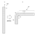
- FIG. 9 is an explanatory diagram of a manufacturing process of the heat exchanger 100 according to the first embodiment.
- Fig. 9 is a plan view of the heat exchanger 100, and in order to show the positional relationship between the header 20 and the flat tubes 10, the outline of the flat tubes 10 is illustrated by dotted lines in the header 20 portion. Note that in Fig. 9, the refrigerant flow path 10a is omitted.
- Figure 9(a) shows an integrated body 100A in which both ends in the tube axis direction of multiple flat tubes 10 are inserted into connection ports (not shown) formed in each of a pair of headers 20, and the entire body is integrated in this state by brazing.
- the integrated body 100A is bent into an L shape as shown in Figure 9(b), thereby producing a heat exchanger 100 having a first heat exchange section 101, a second heat exchange section 102, and a third heat exchange section 103.
- the heat exchanger 100 manufactured by the above manufacturing process has the above-mentioned configuration for at least the flat tubes 10 connected to the L-shaped bend section 23, so damage to the flat tubes 10 is suppressed, making it highly reliable.
- the final heat exchanger 100 may not have the above-mentioned configuration at the connection portions of the flat tubes 10 with the headers 20 at both ends in the axial direction.
- the wall thickness at both ends in the long axis direction may be the same as the wall thickness at the center in the long axis direction.
- the final heat exchanger 100 will have the above-mentioned configuration in the portions other than both ends in the axial direction of the flat tubes 10.
- the heat exchanger 100 of the first embodiment includes a plurality of flat tubes 10 that extend in the vertical direction, have a flattened outer shape, and have a plurality of refrigerant flow paths 10a formed by through holes, and a pair of headers 20 that are connected to both ends of the flat tubes 10 in the vertical direction and have L-shaped L-bends 23 that are L-shaped when viewed from above.
- Each of the flat tubes 10 has a shape having a major axis and a minor axis in a vertical cross section perpendicular to the tube axis direction.
- At least one or more flat tubes 10 connected to the L-bends 23 have a larger wall thickness at both ends in the major axis direction along the major axis in the vertical cross section, and a smaller wall thickness toward the center in the major axis direction.
- the heat exchanger 100 of the above configuration can increase the thickness of the flat tubes 10 on the outside of the bend where the amount of elongation in the L-bend portion 23 of the pair of headers 20 is large, thereby increasing the strength and suppressing damage to the flat tubes 10.
- the thickness of the center of the long axis direction of the flat tube is thinner than the thickness of both ends in the long axis direction, so that the flow path cross-sectional area can be secured and the increase in pressure loss can be suppressed compared to a configuration in which the thickness of the center in the long axis direction is as large as the thickness of both ends.
- the heat exchanger 100 can suppress the increase in pressure loss while improving the strength of the flat tubes 10.
- Each of the one or more flat tubes 10 has at least one of the configurations (1) to (4) above.
- the heat exchanger 100 can increase the thickness of the flat tubes 10 on the outside of the bend where the amount of elongation is greater in the L-bend portion 23 of the pair of headers 20, thereby increasing the strength and suppressing damage to the flat tubes 10.
- Embodiment 2 The heat exchanger 100 of the second embodiment differs from the first embodiment in the configuration of the flat tubes 10.
- the wall thickness of the flat tubes 10 is specified.
- the wall thickness area of the flat tubes 10 is specified.
- the flat tube 10 is a diagram showing a vertical cross section of the flat tube 10 of the heat exchanger 100 according to embodiment 2.
- the flat tube 10 of the heat exchanger 100 according to embodiment 2 has at least one of the following configurations (a) to (b).
- the flat tube 10 has a relationship of Ao>Ac.
- Ao thickness area of the part inside the pair of imaginary lines L4 of the minor axis passage ends in the outer end region Ro.
- Ac thickness area of the part inside the pair of imaginary lines L4 of the minor axis passage ends in the central region Rc.
- Ao1 thickness area of the region R1.
- Ao2 thickness area of the region R4.
- Ao corresponds to the total thickness area of the portions inward from a pair of imaginary lines L4 at the short axis flow paths in regions R2 and R3.
- Ao corresponds to the total thickness area of the portions inward from a pair of imaginary lines L4 at the short axis flow paths in regions R1 and R4.
- the total area of the portions indicated by thick dots is the thickness area Ao
- the total area of the portions indicated by light dots is the thickness area Ac.
- the condition (b) above is that, of the four regions R1, R2, R3, and R4, the wall thickness area Ao1 of region R1 and the wall thickness area Ao2 of region R4, which are the two regions at both ends in the longitudinal direction, are the same.
- This condition specifies that the flat tube 10 is not, for example, wedge-shaped in vertical cross section, but that the outer column 17 portion is symmetrical or nearly symmetrical about the center line L1.
- the heat exchanger 100 of the second embodiment can obtain the same effects as those of the first embodiment.
- Embodiment 3 The heat exchanger 100 of the third embodiment differs from the first embodiment in the configuration of the flat tubes 10.
- the third embodiment relates to the flow path cross-sectional area of the refrigerant flow path 10a of the flat tubes 10. The following description will focus on the differences between the third embodiment and the first embodiment, and the configuration not described in the third embodiment is the same as the first embodiment.
- Fig. 11 is a diagram showing a vertical cross section of a flat tube 10 of a heat exchanger 100 according to embodiment 3.
- the sum of the flow path cross-sectional areas of the multiple refrigerant flow paths 10a2 located in the outer end region Ro is smaller than the sum of the flow path cross-sectional areas of the multiple refrigerant flow paths 10a1 located in the central region Rc.
- the dark dots indicate the flow path cross-sectional areas of the refrigerant flow paths 10a2 located in the outer end region Ro
- the light dots indicate the flow path cross-sectional areas of the refrigerant flow paths 10a1 located in the central region Rc.
- the heat exchanger 100 of embodiment 3 can achieve the same effects as embodiment 1.
- FIG. 12 is an explanatory diagram of the drift of liquid refrigerant in the header 120.
- liquid refrigerant that flows into the header 120 drifts due to the influence of centrifugal force at the L-shaped bend 123, and may flow excessively outside the bend of the L-shaped bend 123, as shown in the area surrounded by the dotted circle in FIG. 12.
- the dots in FIG. 12 indicate liquid refrigerant that has accumulated in the L-shaped bend 123.
- the sum of the cross-sectional areas of the refrigerant flow paths 10a2 located in the outer end region Ro of the flat tube 10 is smaller than the sum of the cross-sectional areas of the refrigerant flow paths 10a1 located in the central region Rc. Therefore, in the heat exchanger 100, among the multiple refrigerant flow paths 10a aligned in the longitudinal direction in the vertical cross section of the flat tube 10, liquid refrigerant is less likely to flow into the refrigerant flow path 10a2 on the outside of the bend than into the refrigerant flow path 10a1 in the central portion in the longitudinal direction. Therefore, the heat exchanger 100 of the third embodiment can suppress excessive liquid refrigerant from flowing into the refrigerant flow path 10a2 on the outside of the bend.
- the heat exchanger 100 of the third embodiment can obtain the same effects as those of the first embodiment, and can also suppress an excessive flow of liquid refrigerant into the refrigerant flow path 10a2 on the outer side of the bend in the flat tube 10.
- Embodiment 4 The heat exchanger 100 of the fourth embodiment relates to the flow path cross-sectional area of the refrigerant flow path 10a of the flat tube 10, similarly to the heat exchanger 100 of the third embodiment.
- the following description will focus on the differences between the fourth embodiment and the third embodiment, and the configuration not described in the fourth embodiment is the same as the third embodiment.
- FIG. 13 is a diagram showing a vertical cross section of a flat tube 10 of a heat exchanger 100 according to embodiment 4.
- the flat tube 10 of embodiment 4 has a configuration in which the width between the centers of adjacent inner columns 16 in the longitudinal direction becomes shorter from the center of the flat tube 10 in the longitudinal direction toward the outside.
- the flat tube 10 has widths W1 and W2 as the width between the centers of adjacent inner columns 16 in the longitudinal direction, and width W2 is shorter than width W1.
- the flat tube 10 has widths W1a and W2a as the longitudinal widths of the refrigerant flow path 10a itself, and width W2a is shorter than width W1a.
- the heat exchanger 100 of the fourth embodiment can obtain the same effects as those of the third embodiment.
- Embodiment 5 The heat exchanger 100 of the fifth embodiment differs from that of the first embodiment in the configuration of the flat tubes 10. The following description will focus on the differences between the fifth embodiment and the first embodiment, and the configuration not described in the fifth embodiment is the same as that of the first embodiment.
- FIG. 14 is a diagram showing a vertical cross section of a flat tube 10 of a heat exchanger 100 according to embodiment 5.
- the central refrigerant flow path 10a1 is rectangular, and at least the end refrigerant flow paths 10a21 at both ends in the longitudinal direction have a curved rectangular shape with R at the four corners.
- the cross-sectional area of the end refrigerant flow path 10a21 is smaller than the cross-sectional area of the other refrigerant flow paths 10a due to the R, and the wall thickness around the end refrigerant flow path 10a21 is thicker accordingly.
- the flat tube 10 has a thicker wall around the end refrigerant flow path 10a21 than around the other refrigerant flow paths 10a.
- the heat exchanger 100 of embodiment 5 allows the heat exchanger 100 of embodiment 5 to increase the thickness of both ends in the longitudinal direction in the vertical cross section of the flat tube 10, thereby improving the fracture strength of the flat tube 10.
- FIG. 14 of the multiple refrigerant flow paths 10a only the end refrigerant flow paths 10a21 at both ends in the longitudinal direction have a curved rectangular shape with R at the four corners, but this is not limited to the end refrigerant flow paths 10a21.
- the end refrigerant flow paths 10a21 at both ends in the longitudinal direction and the refrigerant flow path 10a3 inside them may also have a curved rectangular shape with R at the four corners.
- the heat exchanger 100 of the fifth embodiment can obtain the same effects as those of the first embodiment.
- Embodiment 6 The heat exchanger 100 of the sixth embodiment differs from that of the first embodiment in the configuration of the flat tubes 10. The following description will focus on the differences between the sixth embodiment and the first embodiment, and the configuration not described in the sixth embodiment is the same as that of the first embodiment.
- FIG. 15 is a diagram showing a vertical cross section of a flat tube 10 of a heat exchanger 100 according to embodiment 6.
- the central refrigerant flow path 10a1 of the multiple refrigerant flow paths 10a arranged in the longitudinal direction is rectangular, and at least the end refrigerant flow paths 10a21 at both ends in the longitudinal direction are D-shaped.
- the D-shape is a shape in which, in the vertical cross section of the flat tube 10, a curved portion that is convex outward in the longitudinal direction and a straight portion connecting both ends of the curved portion are formed.
- the cross-sectional area of the end refrigerant flow path 10a21 is smaller than the cross-sectional area of the other refrigerant flow paths 10a due to the D-shape, and the wall thickness around the end refrigerant flow path 10a21 is thicker accordingly.
- the periphery of the end refrigerant flow path 10a21 of the flat tube 10 is thicker than the periphery of the other refrigerant flow paths 10a.
- the heat exchanger 100 of embodiment 6 can increase the wall thickness at both ends in the longitudinal direction in the vertical cross section of the flat tube 10, thereby improving the breaking strength of the flat tube 10.
- the end refrigerant flow paths 10a21 at both ends in the longitudinal direction of the multiple refrigerant flow paths 10a have a D-shape, but this is not limited to the end refrigerant flow paths 10a21.
- the end refrigerant flow paths 10a21 at both ends in the longitudinal direction of the multiple refrigerant flow paths 10a of the heat exchanger 100 and the refrigerant flow path 10a3 inside them may also have a D-shape.
- the heat exchanger 100 of the sixth embodiment can obtain the same effects as those of the first embodiment.
- Embodiment 7 The heat exchanger 100 of the seventh embodiment specifies the relationship among the major axis length Tw [mm] of the flat tubes 10, the pitch interval Dp [mm] of the flat tubes 10, and the bendable radius R0 [mm] of the L-bending portion, which can suppress breakage of the flat tubes 10.
- the following description will focus on the differences between the seventh embodiment and the first embodiment, and the configuration not described in the seventh embodiment is the same as the first embodiment.
- Fig. 16 is a graph showing the relationship between the major axis length Tw of the flat tube 10 and the bending radius R0 of the L-bend portion 23 in the heat exchanger 100 according to the seventh embodiment.
- the horizontal axis shows the major axis length Tw [mm] of the flat tube 10
- the vertical axis shows the bending radius R0 [mm] of the L-bend portion 23.
- Fig. 16 shows the bending radius R0 according to the major axis length Tw of the flat tube 10 when ⁇ 2 / ⁇ 1 is 1, 2, 3, and 4.
- the bending radius R0 is the minimum bending radius of the L-bend portion 23 that can suppress breakage of the flat tube 10.
- Each graph in FIG. 16 is obtained by substituting the value of ⁇ 2 / ⁇ 1 into the right-hand side of the following equation (1).
- the heat exchanger 100 satisfies the relationship of formula (1) above when the flat tubes 10 have a relationship of 1 ⁇ ⁇ 2 / ⁇ 1 .
- the bending radius R of the L-bend portion 23 satisfies R>R1.
- the heat exchanger 100 satisfies the relationship of formula (1) above when the flat tubes 10 have a relationship of 2 ⁇ ⁇ 2 / ⁇ 1 .
- the heat exchanger 100 can suppress breakage of the flat tubes 10.
- the heat exchanger 100 of the seventh embodiment can obtain the same effects as those of the first embodiment.
- Embodiment 8 relates to a refrigeration cycle apparatus such as an air conditioner in which the heat exchanger 100 according to any one of the first to seventh embodiments is mounted.
- FIG 17 is a refrigerant circuit diagram showing the general configuration of a refrigeration cycle apparatus 300 relating to embodiment 8.
- the refrigeration cycle apparatus 300 is equipped with a refrigerant circuit in which a compressor 200, an intake muffler 201, a four-way switching valve 202, an outdoor heat exchanger 203, a pressure reducer 204 such as an electric expansion valve, and an indoor heat exchanger 205 are connected by piping.
- the outdoor heat exchanger 203 and the indoor heat exchanger 205 function as a condenser or an evaporator depending on the switching of the four-way switching valve 202.
- the four-way switching valve 202 can be omitted in the refrigeration cycle apparatus 300.
- the refrigeration cycle apparatus 300 may be configured to include a compressor 200, a condenser, a pressure reducer, and an evaporator.
- the indoor heat exchanger 205 is installed in the indoor unit, and the remaining compressor 200, four-way switching valve 202, outdoor heat exchanger 203, and pressure reducer 204 are installed in the outdoor unit.
- Compressor 200 draws in refrigerant and compresses it to a high temperature and high pressure state.
- Compressor 200 is a volumetric compressor that can vary its operating frequency.
- Compressor 200 is not limited to being driven with a variable operating frequency, and may be a constant speed compressor.
- Four-way switching valve 202 is connected to the discharge side of compressor 200 and switches the flow of refrigerant from compressor 200.
- the outdoor heat exchanger 203 is a fin-tube type heat exchanger including a pipe through which the refrigerant flows and fins into which the pipes are inserted.
- the pressure reducer 204 expands the refrigerant.
- the pressure reducer 204 is formed, for example, of an electronic expansion valve or a temperature-type expansion valve whose opening can be adjusted, but may also be formed of a capillary tube whose opening cannot be adjusted.
- the indoor heat exchanger 205 is a fin-tube type heat exchanger including a pipe through which the refrigerant flows and fins into which the pipes are inserted.
- the heat exchanger 100 according to any one of the first to seventh embodiments is used for at least one of the outdoor heat exchanger 203 and the indoor heat exchanger 205.
- the four-way switching valve 202 In heating operation when the refrigeration cycle device 300 is applied to an air conditioner, the four-way switching valve 202 is connected to the solid line side in FIG. 17.
- the high-temperature, high-pressure refrigerant compressed by the compressor 200 flows to the indoor heat exchanger 205, where it condenses and liquefies.
- the liquefied refrigerant is decompressed by the pressure reducer 204, becomes a two-phase state of low temperature and low pressure, flows to the outdoor heat exchanger 203, evaporates, gasifies, and returns to the compressor 200 again through the four-way switching valve 202.
- the refrigerant circulates as shown by the solid arrows in FIG. 17.
- the refrigerant exchanges heat with the outside air in the outdoor heat exchanger 203, which is an evaporator, and absorbs heat.
- the refrigerant that has absorbed heat is sent to the indoor heat exchanger 205, which is a condenser, and exchanges heat with the indoor air to warm the indoor air.
- the four-way switching valve 202 is connected to the dashed line side in FIG. 17.
- the indoor heat exchanger 205 changes from a condenser to an evaporator
- the outdoor heat exchanger 203 changes from an evaporator to a condenser.
- the high-temperature, high-pressure refrigerant compressed by the compressor 200 flows to the outdoor heat exchanger 203, where it condenses and liquefies.
- the liquefied refrigerant is depressurized by the pressure reducer 204 and becomes a low-temperature, low-pressure two-phase state.
- the low-temperature, low-pressure two-phase refrigerant flows to the indoor heat exchanger 205, where it evaporates and gasifies, and returns to the compressor 200 again through the four-way switching valve 202.
- the refrigerant circulates as shown by the dashed arrows in FIG. 17.
- the indoor heat exchanger 205 which is an evaporator
- the refrigerant exchanges heat with the indoor air, absorbing heat and cooling the indoor air.
- the refrigerant that has absorbed heat is sent to the outdoor heat exchanger 203, which is a condenser, where it exchanges heat with the outside air and dissipates heat into the outside air.
- refrigerants such as R407C, R410A or R32 are used.
- the refrigeration cycle device 300 configured as described above includes a heat exchanger 100 according to any one of the first to seventh embodiments, thereby improving the strength of the flat tubes 10 while suppressing an increase in the pressure loss of the refrigerant.
- the refrigeration cycle device 300 can be used in applications other than air conditioners, such as refrigerators, freezers, vending machines, refrigeration devices, or water heaters.
Landscapes
- Engineering & Computer Science (AREA)
- Physics & Mathematics (AREA)
- Thermal Sciences (AREA)
- Mechanical Engineering (AREA)
- General Engineering & Computer Science (AREA)
- Heat-Exchange Devices With Radiators And Conduit Assemblies (AREA)
Priority Applications (4)
| Application Number | Priority Date | Filing Date | Title |
|---|---|---|---|
| EP23938390.4A EP4718009A1 (en) | 2023-05-22 | 2023-05-22 | Heat exchanger and refrigeration cycle device comprising said heat exchanger |
| JP2024517469A JP7706650B2 (ja) | 2023-05-22 | 2023-05-22 | 熱交換器、この熱交換器の製造方法およびこの熱交換器を備えた冷凍サイクル装置 |
| PCT/JP2023/018916 WO2024241417A1 (ja) | 2023-05-22 | 2023-05-22 | 熱交換器およびこの熱交換器を備えた冷凍サイクル装置 |
| CN202380098062.8A CN121219545A (zh) | 2023-05-22 | 2023-05-22 | 热交换器以及具备该热交换器的制冷循环装置 |
Applications Claiming Priority (1)
| Application Number | Priority Date | Filing Date | Title |
|---|---|---|---|
| PCT/JP2023/018916 WO2024241417A1 (ja) | 2023-05-22 | 2023-05-22 | 熱交換器およびこの熱交換器を備えた冷凍サイクル装置 |
Publications (1)
| Publication Number | Publication Date |
|---|---|
| WO2024241417A1 true WO2024241417A1 (ja) | 2024-11-28 |
Family
ID=93588988
Family Applications (1)
| Application Number | Title | Priority Date | Filing Date |
|---|---|---|---|
| PCT/JP2023/018916 Ceased WO2024241417A1 (ja) | 2023-05-22 | 2023-05-22 | 熱交換器およびこの熱交換器を備えた冷凍サイクル装置 |
Country Status (4)
| Country | Link |
|---|---|
| EP (1) | EP4718009A1 (https=) |
| JP (1) | JP7706650B2 (https=) |
| CN (1) | CN121219545A (https=) |
| WO (1) | WO2024241417A1 (https=) |
Citations (9)
| Publication number | Priority date | Publication date | Assignee | Title |
|---|---|---|---|---|
| JPH02230091A (ja) * | 1989-03-01 | 1990-09-12 | Hitachi Ltd | サーペンタイン形熱交換器 |
| JPH1144498A (ja) * | 1997-05-30 | 1999-02-16 | Showa Alum Corp | 熱交換器用偏平多孔チューブ及び同チューブを用いた熱交換器 |
| JP2005037113A (ja) * | 2003-06-23 | 2005-02-10 | Denso Corp | 熱交換器 |
| JP2005090806A (ja) * | 2003-09-16 | 2005-04-07 | Matsushita Electric Ind Co Ltd | 熱交換器 |
| JP2005524820A (ja) * | 2002-05-07 | 2005-08-18 | ヴァレオ インコーポレイテッド | 熱交換器 |
| JP2007093144A (ja) * | 2005-09-29 | 2007-04-12 | Denso Corp | 熱交換用チューブおよび熱交換器 |
| JP2010065989A (ja) * | 2008-09-13 | 2010-03-25 | Calsonic Kansei Corp | 熱交換器用チューブ及び熱交換器 |
| JP2021060130A (ja) * | 2019-10-03 | 2021-04-15 | 三菱電機株式会社 | 熱交換器及び、熱交換器の製造方法 |
| JP7037090B2 (ja) | 2020-07-17 | 2022-03-16 | ダイキン工業株式会社 | 熱交換器 |
-
2023
- 2023-05-22 EP EP23938390.4A patent/EP4718009A1/en active Pending
- 2023-05-22 WO PCT/JP2023/018916 patent/WO2024241417A1/ja not_active Ceased
- 2023-05-22 CN CN202380098062.8A patent/CN121219545A/zh active Pending
- 2023-05-22 JP JP2024517469A patent/JP7706650B2/ja active Active
Patent Citations (9)
| Publication number | Priority date | Publication date | Assignee | Title |
|---|---|---|---|---|
| JPH02230091A (ja) * | 1989-03-01 | 1990-09-12 | Hitachi Ltd | サーペンタイン形熱交換器 |
| JPH1144498A (ja) * | 1997-05-30 | 1999-02-16 | Showa Alum Corp | 熱交換器用偏平多孔チューブ及び同チューブを用いた熱交換器 |
| JP2005524820A (ja) * | 2002-05-07 | 2005-08-18 | ヴァレオ インコーポレイテッド | 熱交換器 |
| JP2005037113A (ja) * | 2003-06-23 | 2005-02-10 | Denso Corp | 熱交換器 |
| JP2005090806A (ja) * | 2003-09-16 | 2005-04-07 | Matsushita Electric Ind Co Ltd | 熱交換器 |
| JP2007093144A (ja) * | 2005-09-29 | 2007-04-12 | Denso Corp | 熱交換用チューブおよび熱交換器 |
| JP2010065989A (ja) * | 2008-09-13 | 2010-03-25 | Calsonic Kansei Corp | 熱交換器用チューブ及び熱交換器 |
| JP2021060130A (ja) * | 2019-10-03 | 2021-04-15 | 三菱電機株式会社 | 熱交換器及び、熱交換器の製造方法 |
| JP7037090B2 (ja) | 2020-07-17 | 2022-03-16 | ダイキン工業株式会社 | 熱交換器 |
Non-Patent Citations (1)
| Title |
|---|
| See also references of EP4718009A1 |
Also Published As
| Publication number | Publication date |
|---|---|
| JPWO2024241417A1 (https=) | 2024-11-28 |
| JP7706650B2 (ja) | 2025-07-11 |
| EP4718009A1 (en) | 2026-04-01 |
| CN121219545A (zh) | 2025-12-26 |
Similar Documents
| Publication | Publication Date | Title |
|---|---|---|
| EP2653816B1 (en) | Bendable core unit. | |
| CN102959353B (zh) | 带有可变形隔壁的多通道管 | |
| EP1438545B1 (en) | Finned tube for heat exchangers, heat exchanger, process for producing heat exchanger finned tube, and process for fabricating heat exchanger | |
| JP5195733B2 (ja) | 熱交換器及びこれを備えた冷凍サイクル装置 | |
| EP2667134A1 (en) | Heat exchanger and air conditioner | |
| EP2653820A1 (en) | Heat exchanger and air conditioner | |
| EP3637033B1 (en) | Heat exchanger and refrigeration cycle device | |
| EP4155652B1 (en) | Heat exchanger and air conditioner | |
| JP6890509B2 (ja) | 空気調和機 | |
| WO2007013439A1 (ja) | 熱交換器 | |
| WO2014076757A1 (ja) | 扁平形状伝熱管、それを備えたクロスフィンチューブ型熱交換器の製造方法、その方法で製造されたクロスフィンチューブ型熱交換器 | |
| JP7706650B2 (ja) | 熱交換器、この熱交換器の製造方法およびこの熱交換器を備えた冷凍サイクル装置 | |
| JP7462832B2 (ja) | 熱交換器 | |
| CN209054801U (zh) | 热交换器以及制冷循环装置 | |
| WO2017208419A1 (ja) | フィンチューブ型熱交換器、このフィンチューブ型熱交換器を備えたヒートポンプ装置、および、フィンチューブ型熱交換器の製造方法 | |
| WO2024089927A1 (ja) | 熱交換器およびこの熱交換器を備えた冷凍サイクル装置 | |
| WO2023032155A1 (ja) | 熱交換器、冷凍サイクル装置及び熱交換器の製造方法 | |
| JP7170859B2 (ja) | 熱交換器及び冷凍サイクル装置 | |
| JP7496832B2 (ja) | 熱交換器、熱交換器ユニット、冷凍サイクル装置、及び熱交換部材の製造方法 | |
| JP7738754B2 (ja) | 熱交換器及び冷凍サイクル装置 | |
| WO2024224513A1 (ja) | 熱交換器及び空気調和装置 | |
| WO2024247213A1 (ja) | 熱交換器及び空気調和装置 | |
| WO2024089798A1 (ja) | 熱交換器及びこの熱交換器を備えた冷凍サイクル装置 | |
| WO2025069234A1 (ja) | 熱交換器、室外機および空気調和装置 | |
| WO2025177939A1 (ja) | 熱交換器製造方法、熱交換器、及び空調装置 |
Legal Events
| Date | Code | Title | Description |
|---|---|---|---|
| WWE | Wipo information: entry into national phase |
Ref document number: 2024517469 Country of ref document: JP |
|
| 121 | Ep: the epo has been informed by wipo that ep was designated in this application |
Ref document number: 23938390 Country of ref document: EP Kind code of ref document: A1 |
|
| ENP | Entry into the national phase |
Ref document number: 2023938390 Country of ref document: EP Effective date: 20251222 |
|
| WWE | Wipo information: entry into national phase |
Ref document number: 2023938390 Country of ref document: EP |
|
| NENP | Non-entry into the national phase |
Ref country code: DE |
|
| ENP | Entry into the national phase |
Ref document number: 2023938390 Country of ref document: EP Effective date: 20251222 |
|
| ENP | Entry into the national phase |
Ref document number: 2023938390 Country of ref document: EP Effective date: 20251222 |
|
| ENP | Entry into the national phase |
Ref document number: 2023938390 Country of ref document: EP Effective date: 20251222 |
|
| ENP | Entry into the national phase |
Ref document number: 2023938390 Country of ref document: EP Effective date: 20251222 |
|
| ENP | Entry into the national phase |
Ref document number: 2023938390 Country of ref document: EP Effective date: 20251222 |
|
| ENP | Entry into the national phase |
Ref document number: 2023938390 Country of ref document: EP Effective date: 20251222 |
|
| ENP | Entry into the national phase |
Ref document number: 2023938390 Country of ref document: EP Effective date: 20251222 |
|
| WWP | Wipo information: published in national office |
Ref document number: 2023938390 Country of ref document: EP |