WO2024237286A1 - 素線データ処理システム、制御装置、制御方法、及び制御プログラム - Google Patents
素線データ処理システム、制御装置、制御方法、及び制御プログラム Download PDFInfo
- Publication number
- WO2024237286A1 WO2024237286A1 PCT/JP2024/017990 JP2024017990W WO2024237286A1 WO 2024237286 A1 WO2024237286 A1 WO 2024237286A1 JP 2024017990 W JP2024017990 W JP 2024017990W WO 2024237286 A1 WO2024237286 A1 WO 2024237286A1
- Authority
- WO
- WIPO (PCT)
- Prior art keywords
- wire
- coil spring
- wire data
- sensor
- cross
- Prior art date
- Legal status (The legal status is an assumption and is not a legal conclusion. Google has not performed a legal analysis and makes no representation as to the accuracy of the status listed.)
- Ceased
Links
Images



Classifications
-
- G—PHYSICS
- G01—MEASURING; TESTING
- G01B—MEASURING LENGTH, THICKNESS OR SIMILAR LINEAR DIMENSIONS; MEASURING ANGLES; MEASURING AREAS; MEASURING IRREGULARITIES OF SURFACES OR CONTOURS
- G01B11/00—Measuring arrangements characterised by the use of optical techniques
- G01B11/24—Measuring arrangements characterised by the use of optical techniques for measuring contours or curvatures
- G01B11/25—Measuring arrangements characterised by the use of optical techniques for measuring contours or curvatures by projecting a pattern, e.g. one or more lines, moiré fringes on the object
- G01B11/2518—Projection by scanning of the object
-
- B—PERFORMING OPERATIONS; TRANSPORTING
- B05—SPRAYING OR ATOMISING IN GENERAL; APPLYING FLUENT MATERIALS TO SURFACES, IN GENERAL
- B05C—APPARATUS FOR APPLYING FLUENT MATERIALS TO SURFACES, IN GENERAL
- B05C13/00—Means for manipulating or holding work, e.g. for separate articles
- B05C13/02—Means for manipulating or holding work, e.g. for separate articles for particular articles
-
- B—PERFORMING OPERATIONS; TRANSPORTING
- B05—SPRAYING OR ATOMISING IN GENERAL; APPLYING FLUENT MATERIALS TO SURFACES, IN GENERAL
- B05C—APPARATUS FOR APPLYING FLUENT MATERIALS TO SURFACES, IN GENERAL
- B05C9/00—Apparatus or plant for applying liquid or other fluent material to surfaces by means not covered by any preceding group, or in which the means of applying the liquid or other fluent material is not important
- B05C9/08—Apparatus or plant for applying liquid or other fluent material to surfaces by means not covered by any preceding group, or in which the means of applying the liquid or other fluent material is not important for applying liquid or other fluent material and performing an auxiliary operation
- B05C9/10—Apparatus or plant for applying liquid or other fluent material to surfaces by means not covered by any preceding group, or in which the means of applying the liquid or other fluent material is not important for applying liquid or other fluent material and performing an auxiliary operation the auxiliary operation being performed before the application
Definitions
- the present invention relates to a wire data processing system, a control device, a control method, and a control program.
- the following shape measuring method has been known as a method for measuring the shape of a coil spring (see, for example, Patent Document 1).
- a linear slit light spreading in the axial direction of a coil spring fixed to a rotation stage is irradiated onto the surface of the coil spring, and the reflected light is captured by a camera to obtain wire data.
- the wire data and the rotation angle when the coil spring is rotated around its axis are stored in association with each other, and the shape of the coil spring is measured by performing image processing on the wire data.
- a coil spring a coil spring in which the cross-sectional shape of the wire changes from both ends toward the center is known (see, for example, Patent Document 2).
- the cross-sectional shape of the wire at both ends is rectangular and the cross-sectional shape of the wire at the center is circular, and the cross-sectional shape of the wire gradually changes from both ends toward the center.
- JP 2010-101693 A Japanese Unexamined Patent Publication No. 155342/1983
- the shape measurement method described in Patent Document 1 is based on the premise that the cross-sectional shape of the wire of the coil spring is a circle, and measures the shape of the coil spring by performing processing corresponding to the circle on the wire data. Therefore, when the coil spring described in Patent Document 2, in which the cross-sectional shape of the wire varies depending on the position, is measured by the shape measurement method described in Patent Document 1, it is not possible to accurately measure the shape of the coil spring for the portion whose cross-sectional shape is not a circle, because processing corresponding to a circle is performed on the wire data. In view of the above, there is a demand for a technique that can perform appropriate processing on wire data.
- the present invention has been made in consideration of the above, and aims to provide a wire data processing system, control device, control method, and control program that can perform appropriate processing on wire data.
- the wire data processing system of the present invention comprises a support mechanism that supports a coil spring and enables the coil spring to rotate around a specific axis that follows the central axis of the coil spring, a sensor that measures the external position of the wire of the coil spring and outputs wire data, and a control device that controls the operation of the support mechanism and the sensor, and the control device comprises a support mechanism control unit that operates the support mechanism and rotates the coil spring around the specific axis, a sensor control unit that operates the sensor and acquires the wire data from the sensor, a shape identification unit that identifies the cross-sectional shape of the wire based on the wire data, and a processing execution unit that executes processing on the wire data that corresponds to the cross-sectional shape of the wire.
- the shape identification unit includes a virtual figure estimation unit that estimates a virtual figure of a predetermined shape that fits a shape formed by each position coordinate corresponding to the outer shape position of the wire in the wire data, an error calculation unit that calculates the error between each position coordinate and the virtual figure, and an identification unit that identifies the cross-sectional shape of the wire based on the error.
- the virtual figure estimation unit uses the position coordinates to estimate a circle, which is the virtual figure, that fits the shape formed by the position coordinates by the least squares method.
- the cross-sectional shape of the wire in the coil spring varies depending on the position.
- the wire data processing system in the above invention, further includes an application device that applies a coating material to the coil spring, and the processing execution unit calculates an application position of the coating material on the coil spring that corresponds to the cross-sectional shape of the wire by executing processing on the wire data that corresponds to the cross-sectional shape of the wire, and the control device includes a movement control unit that moves the application device and the support mechanism relatively and positions the application device at a position where the coating material is applied from the application device to the application position, and a application device control unit that operates the application device and applies the coating material from the application device to the application position.
- the wire data processing system in the above invention, further includes a moving device that supports the coating device and moves the coating device, and the movement control unit operates the moving device to position the coating device at a position where the coating material is applied from the coating device to the coating position.
- the control device also includes a support mechanism control unit that operates a support mechanism that supports a coil spring and rotates the coil spring around a specific axis that follows the central axis of the coil spring, a sensor control unit that operates a sensor that measures the external position of the wire of the coil spring and outputs wire data, and acquires the wire data, a shape identification unit that identifies the cross-sectional shape of the wire based on the wire data, and a processing execution unit that executes processing on the wire data that corresponds to the cross-sectional shape of the wire.
- the control method according to the present invention is a control method executed by a control device of a wire data processing system, and includes a support mechanism control step of operating a support mechanism that supports a coil spring and rotating the coil spring around a specific axis that follows the central axis of the coil spring, a sensor control step of operating a sensor that measures the external position of the wire of the coil spring and outputs wire data to obtain the wire data, a shape identification step of identifying the cross-sectional shape of the wire based on the wire data, and a processing execution step of executing processing on the wire data that corresponds to the cross-sectional shape of the wire.
- the control program according to the present invention is a control program for causing a computer to execute a support mechanism control step of operating a support mechanism that supports a coil spring and rotating the coil spring around a specific axis that follows the central axis of the coil spring, a sensor control step of operating a sensor that measures the external position of the wire of the coil spring and outputs wire data to obtain the wire data, a shape determination step of determining the cross-sectional shape of the wire based on the wire data, and a processing execution step of executing processing on the wire data that corresponds to the cross-sectional shape of the wire.
- the wire data processing system, control device, control method, and control program of the present invention can perform appropriate processing on wire data.
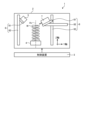
- FIG. 1 is a diagram showing a configuration of a coating material application system according to an embodiment.
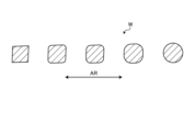
- FIG. 2 is a diagram showing a cross-sectional shape of a wire of a coil spring.
- FIG. 3 is a diagram for explaining the positional relationship between the sensor and the dispenser.
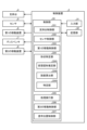
- FIG. 4 is a block diagram showing the configuration of the control device.
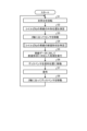
- FIG. 5 is a flowchart showing a control method executed by the control device.
- FIG. 6 is a flow chart showing the shape specifying step (step S4).
- FIG. 7 is a diagram illustrating the shape specifying step (step S4).
- FIG. 8 is a diagram for explaining the process execution step (step S5) when the cross-sectional shape of the wire of the coil spring is identified as a "circle.”
- FIG. 9 is a diagram for explaining the process execution step (step S5) when the cross-sectional shape of the wire of the coil spring is identified as being "rectangle”.
- FIG. 1 is a diagram showing a configuration of a coating material application system 1 according to an embodiment.
- the coating material application system 1 includes a coating material application device 2 and a control device 3.
- the coating material application device 2 operates under the control of the control device 3, and a coating material such as a thermosetting resin or a thermoplastic resin is applied to a specific position (application position) of the coil spring W.
- the application position is a portion where the wires of the coil spring W come into contact with each other when the coil spring W is compressed. In other words, by applying the coating material to the application position, contact damage between the wires of the coil spring W at the application position is mitigated.
- Fig. 2 is a diagram showing the cross-sectional shape of a wire of a coil spring W.
- Fig. 2 is a diagram in which the cross-sectional shapes of the wire of the coil spring W from the end portion to the center portion of the coil spring W are arranged along the central axis of the coil spring W. That is, the direction AR in Fig. 2 is a direction along the central axis of the coil spring W.
- the cross-sectional shape of the wire of the coil spring W gradually changes from rectangular to circular from the end portion (left side in FIG. 2) of the coil spring W toward the center portion (right side in FIG. 2).
- the configuration of the coating material application device 2 will be described.
- the axis along the vertical direction (the up-down direction in FIG. 1) is defined as the Z-axis (FIG. 1)
- one of the two axes perpendicular to the Z-axis (the axis along the left-right direction in FIG. 1) is defined as the Y-axis (FIG. 1).
- the coating material application device 2 includes a support table 4 , a sensor 5 , a first moving device 6 , a dispenser 7 , and a second moving device 8 .
- the support base 4 corresponds to the support mechanism according to the present invention. As shown in FIG. 1, the support base 4 supports the coil spring W. Specifically, the coil spring W is placed on the support base 4 in a position in which the central axis of the coil spring W follows the Z-axis.
- the support base 4 includes a servo motor and the like, and is configured to be rotatable around a specific axis Ax (FIG. 1) that follows the central axis of the coil spring W under the control of the control device 3.
- the specific axis Ax is an axis parallel to the Z-axis.
- the sensor 5 measures the external position of the wire of the coil spring W under the control of the control device 3.
- the sensor 5 is configured with a laser sensor. More specifically, the sensor 5 emits a laser beam in a line shape along the YZ plane from a direction inclined at 45° with respect to the Y-axis and Z-axis.
- the sensor 5 is configured to receive the laser beam reflected from the wire of the coil spring W with an imaging element such as a CMOS (Complementary Metal Oxide Semiconductor) so as to be able to measure the profile of the part of the wire that reflects the line-shaped laser beam.
- the sensor 5 also outputs wire data that measures the external position of the wire of the coil spring W to the control device 3. Note that the inclination angle of the sensor 5 with respect to the Y-axis and Z-axis is not limited to 45° and may be other inclination angles.
- the first moving device 6 supports the sensor 5 and moves the sensor 5.
- the first moving device 6 includes a slider 61 that supports the sensor 5, a guide rail 62 that extends along the Z axis, and a servo motor (not shown).
- the slider 61 moves on the guide rail 62 along the Z axis under the control of the control device 3. That is, in this embodiment, the first moving device 6 moves the sensor 5 only along a specific axis Ax.
- the dispenser 7 corresponds to the application device according to the present invention, and applies the coating material to the coil spring W under the control of the control device 3. Note that the application device according to the present invention is not limited to the dispenser 7, and other application devices may be used.
- the second moving device 8 corresponds to the moving device according to the present invention, and supports the dispenser 7 and moves the dispenser 7.
- the second moving device 8 includes a slider 81 that supports the dispenser 7, a guide rail 82 that extends along the Y axis, a guide rail 83 that extends along the Z axis, and a servo motor (not shown).
- the slider 81 moves on the guide rail 82 along the Y axis
- the guide rail 82 moves on the guide rail 83 along the Z axis. That is, in this embodiment, the second moving device 8 moves the dispenser 7 only along the specific axis Ax and the Y axis.
- Fig. 3 is a diagram for explaining the positional relationship between the sensor 5 and the dispenser 7. Specifically, Fig. 3 is a diagram showing the sensor 5 and the dispenser 7 as viewed from above along the Z axis. The measurement position PM of the outer shape position of the wire of the coil spring W by the sensor 5 and the application position PA of the coating material to the coil spring W by the dispenser 7 are shifted by a specific angle around a specific axis Ax, as shown in FIG. 3 .
- the sensor 5 emits a line-shaped laser light as described above, and measures the profile of the portion of the wire of the coil spring W that reflects the line-shaped laser light. Therefore, the measurement position PM corresponds to the position of that portion.
- the specific angle is 180°. Note that the specific angle is not limited to 180°, and may be another angle.
- FIG. 4 is a block diagram showing the configuration of the control device 3.
- the control device 3 controls the overall operation of the coating material application device 2.
- the control device 3 includes an input unit 31, a storage unit 32, and a control unit 33, as shown in FIG.
- the input unit 31 is composed of buttons, switches, a touch panel, etc. that accept user operations, and outputs a signal corresponding to the user operation to the control unit 33.
- the storage unit 32 stores various programs executed by the control unit 33 (including the control program according to the present invention), as well as data and other information required when the control unit 33 performs processing.
- step S1 support mechanism control step
- data indicating the specific rotation speed is stored in the storage unit 32.
- step S1 the support base control unit 331 reads out the data from the storage unit 32 and rotates the support base 4 at a rotation speed based on the data.
- the data is configured so that the value of the rotation speed can be changed by a user operation on the input unit 31.
- step S1 the sensor control unit 332 operates the sensor 5 to measure the outer shape position of the wire of the coil spring W. Then, the sensor control unit 332 acquires wire data from the sensor 5 (step S2: sensor control step). As described above, the sensor 5 is configured to be able to measure the profile of the wire of the coil spring W. The sensor 5 outputs, as wire data, the position coordinates of each portion of the wire of the coil spring W that reflects the line-shaped laser light output from the sensor 5 (portions corresponding to the outer shape position of the wire of the coil spring W).
- the first movement control unit 333 operates the first movement device 6 to move the sensor 5 along the Z axis at a specific movement speed (step S3).
- the sensor 5 is positioned at a position where it can measure the position of one end of the upper side of the wire of the coil spring W placed on the support base 4, and by executing step S3, it moves downward at the specific speed.
- the sensor 5 is moved from top to bottom, and the coating material is applied from one end of the upper side of the wire of the coil spring W to the other end of the lower side, but conversely, the sensor 5 may be moved from bottom to top, and the coating material may be applied from the other end of the lower side of the wire of the coil spring W to one end of the upper side.
- the memory unit 32 stores data indicating the distance the sensor 5 is moved along the Z axis each time the support base 4 is rotated, for example, by 180°. Then, in step S3, the first movement control unit 333 reads out the data from the memory unit 32 and moves the sensor 5 at a movement speed based on the data. Note that the data is configured so that the value of the movement distance can be changed by user operation on the input unit 31.
- step S3 the shape identification unit 334 identifies the cross-sectional shape of the wire of the coil spring W based on the wire data acquired in step S2 (step S4: shape identification step).
- Fig. 6 is a flowchart showing the shape specifying step (step S4).
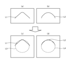
- Fig. 7 is a diagram for explaining the shape specifying step (step S4).
- the solid lines L1 and L2 shown in Fig. 7(a) to (d) indicate wire data (position coordinates of the wire of the coil spring W at the portions reflecting the linear laser light output from the sensor 5).
- the dashed dotted lines L3 and L4 shown in Fig. 7(c) and (d) indicate the virtual figure estimated by the virtual figure estimation unit 3341.
- the virtual figure estimation unit 3341 estimates a virtual figure of a predetermined shape that fits a shape composed of each position coordinate corresponding to the outer shape positions of the wire of the coil spring W in the wire data acquired in step S2 (step S41).
- a circle is used as the virtual figure of the predetermined shape.
- the virtual figure estimation unit 3341 uses the position coordinates of each position in the wire data acquired in step S2 to estimate a circle (hereinafter referred to as a virtual circle) that best fits the shape formed by each of the position coordinates, for example by the least squares method.
- the error calculation unit 3342 calculates the error (e.g., mean square error) between each position coordinate in the wire data acquired in step S2 and the virtual circle estimated in step S41 (step S42).
- the error e.g., mean square error
- the identification unit 3343 identifies the cross-sectional shape of the wire of the coil spring W based on the error calculated in step S42 (step S43).
- the wire data acquired in step S2 is the data shown in (a) of Figure 7 (the cross-sectional shape of the wire at the measurement position PM is "rectangle" at the timing when the sensor 5 measures the outer position of the wire of the coil spring W in step S2).
- the error between each position coordinate (solid line L1) in the wire data and the virtual circle (dashed line L3) estimated in step S41 is relatively large.
- the identification unit 3343 compares the error calculated in step S42 with a specific threshold value, and if the error is greater than the threshold value, identifies the cross-sectional shape of the wire of the coil spring W as "rectangle.”
- the wire data acquired in step S2 is the data in (b) of Figure 7 (the cross-sectional shape of the wire at the measurement position PM is a "circle" at the timing when the sensor 5 measures the outer position of the wire of the coil spring W in step S2).
- the error between each position coordinate in the wire data (solid line L2) and the virtual circle (dotted line L4) estimated in step S41 is relatively small.
- the identification unit 3343 compares the error calculated in step S42 with the above-mentioned threshold, and if the error is equal to or less than the threshold, identifies the cross-sectional shape of the wire of the coil spring W as a "circle.”
- step S4 the process execution unit 335 executes a process corresponding to the cross-sectional shape of the wire of the coil spring W identified in step S4 on the wire data acquired in step S2 (step S5: process execution step).
- step S5 process execution step
- the process execution unit 335 calculates, through this process, the position coordinates P2 (y, z) of the application position of the coating material on the coil spring W corresponding to the cross-sectional shape of the wire of the coil spring W identified in step S4.
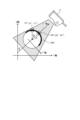
- FIG. 8 is a diagram for explaining the process execution step (step S5) when the cross-sectional shape of the wire of the coil spring W is specified to be a "circle". Specifically, FIG. 8 shows the emission area (YZ plane) of the linear laser light emitted from the sensor 5. In FIG. 8, the emission area of the laser light is expressed by dots.
- the Y'-axis and Z'-axis shown in FIG. 8 are coordinate axes measured by the sensor 5 (hereinafter, referred to as sensor coordinate axes).
- the Y-axis and Z-axis are referred to as device coordinate axes to distinguish them from the sensor coordinate axes.
- the sensor 5 is installed so as to emit the laser light in a line shape along the YZ plane from a direction inclined at 45° with respect to the Y-axis and Z-axis, as described above.
- the Y'-axis and Z'-axis are rotated by 45° with respect to the Y-axis and Z-axis, respectively, as shown in FIG. 8.
- the Z'-axis corresponds to the direction of the laser light output from the sensor 5.
- the processing execution unit 335 extracts the position coordinate P0' (y0', z0') and radius R from the wire data acquired in step S2.
- the position coordinate P0' (y0', z0') is a position coordinate on the sensor coordinate axis, and is the position coordinate of the vertex of the part WA (represented by a thick line in Figure 8) in the wire of the coil spring W that reflects the linear laser light output from the sensor 5.
- the radius R is the radius of a virtual circle (dashed dotted line L4 in Figure 7 (d)) that includes the part WA.
- the processing execution unit 335 calculates the position coordinate P1' (y1', z1') of the application position on the part WA based on the position coordinate P0' (y0', z0') and the radius R using the following formula (1).
- position coordinate P1' (y1', z1') is a position coordinate on the sensor coordinate axis, and is the position coordinate with the highest coordinate value in the Z-axis direction on a virtual circle that includes part WA (FIG. 8).
- ⁇ is an angle according to the installation position of sensor 5, and is 45° in this embodiment. The same applies to formula (2) below.
- the process execution unit 335 converts the position coordinate P1' (y1', z1') on the sensor coordinate axis into the position coordinate P1 (y1, z1) on the device coordinate axis using the following equation (2).
- the process execution unit 335 calculates the position coordinate P2 (y2, z2) by rotating the position coordinate P1 (y1, z1) by 180° around a specific axis Ax (Z axis), and calculates the position coordinate P2 (y2, z2) as the application position.
- FIG. 9 is a diagram for explaining the process execution step (step S5) when the cross-sectional shape of the wire of the coil spring W is specified to be "rectangle.” Specifically, FIG. 9 is a diagram corresponding to FIG.
- the processing execution unit 335 extracts position coordinates P01' (y01', z01') and P02' (y02', z02') from the wire data acquired in step S2.
- the position coordinates P01' (y01', z01') and P02' (y02', z02') are position coordinates on the sensor coordinate axis, and are the position coordinates of two edges of the wire of the coil spring W that have high coordinate values in the Z-axis direction on the part WR (represented by a thick line in Figure 9) that reflects the linear laser light output from the sensor 5.
- the processing execution unit 335 then calculates the midpoint of the position coordinates P01' (y01', z01') and P02' (y02', z02') of the two edges as position coordinate P1' (y1', z1') ( Figure 9). After this, the process execution unit 335 calculates the position coordinates P1 (y1, z1) and P2 (y2, z2) from the position coordinate P1' (y1', z1') in the same manner as in the above-mentioned "Process execution step (step S5) when the cross-sectional shape of the wire of the coil spring W is identified as 'circle'".
- step S5 the second movement control unit 336 operates the second movement device 8 to move the dispenser 7 to a position where the coating material is applied from the dispenser 7 to the application position (position coordinates P2 (y2, z2)) (step S6).
- the coating device control unit 337 operates the dispenser 7 at a coating timing when the support table 4 has rotated 180° around a specific axis Ax from the measurement timing, and causes the dispenser 7 to apply the coating material to the coating position (position coordinates P2 (y2, z2)) (step S7).
- the measurement timing is the timing when the sensor 5 measures the position of the wire of the coil spring W in step S2.
- the second movement control unit 336 operates the second movement device 8 to move the dispenser 7 along the Z axis at a specific movement speed (step S8).
- the specific movement speed is the same as the specific movement speed of the sensor 5 in step S3.
- the coating material is applied to the wire of the coil spring W from one end to the other.
- the control device 3 rotates the support base 4 about a specific axis Ax.
- the control device 3 also operates the sensor 5 to acquire wire data from the sensor 5.
- the control device 3 further identifies the cross-sectional shape of the wire of the coil spring W based on the wire data.
- the control device 3 then executes processing on the wire data that corresponds to the cross-sectional shape of the wire of the coil spring W. Therefore, even if the cross-sectional shape of the wire of the coil spring W varies depending on the position, appropriate processing corresponding to the cross-sectional shape can be performed on the wire data.
- the wire data processing system is applied to a coating material application system 1 that applies a coating material to a coil spring W.
- the control device 3 executes processing corresponding to the cross-sectional shape of the wire data to calculate an application position of the coating material on the coil spring W corresponding to the cross-sectional shape.
- the control device 3 moves the second moving device 8 to move the dispenser 7 to a position where the coating material is applied to the application position, and operates the dispenser 7 to apply the coating material from the dispenser 7 to the application position. Therefore, even if the cross-sectional shape of the wire of the coil spring W varies depending on the position, the application position on the coil spring W will not deviate from the desired position, and the coating material can be applied to the coil spring W with high precision.
- the control device 3 estimates a virtual figure of a predetermined shape that fits the shape formed by each position coordinate that corresponds to the outer shape position of the wire of the coil spring W in the wire data.
- the control device 3 estimates a circle, which is the virtual figure that fits the shape formed by each position coordinate, by the least squares method using each of the position coordinates.
- the control device 3 also calculates the error between each of the position coordinates and the virtual figure. Then, the control device 3 specifies the cross-sectional shape of the coil spring W based on the error. Therefore, the cross-sectional shape of the coil spring W can be determined with high accuracy by simple calculation.
- the wire data processing system according to the present invention is applied to the coating material application system 1, but the present invention is not limited to this.
- the wire data processing system of the present invention may be applied to a coil spring inspection system that performs processing on wire data corresponding to the cross-sectional shape of the wire of a coil spring W, calculates position coordinates and dimensions of specific locations corresponding to the cross-sectional shape, and inspects the coil spring W.
- the wire data processing system of the present invention may be applied to a coil spring processing system that performs processing on wire data corresponding to the cross-sectional shape of the wire of a coil spring W, calculates position coordinates of a specific location corresponding to the cross-sectional shape, and performs processing at the position of the position coordinates on the coil spring W.
- a circle is used as the virtual figure according to the present invention, but this is not limiting and a rectangle may also be used.
- the virtual figure according to the present invention may be any shape that corresponds to the cross-sectional shape of the wire of the coil spring W. For example, if the cross-sectional shape of the wire at a certain position of the coil spring W is triangular, a triangle may be used as the virtual figure according to the present invention.
- a coil spring W in which the cross-sectional shape of the wire varies depending on the position is used as the coil spring according to the present invention, but this is not limited to the above, and a coil spring in which the cross-sectional shape of the wire is the same depending on the position may also be used.
- the first moving device 6 moves the sensor 5 only along the Z axis, but this is not limited to this, and the sensor 5 may be configured to be movable in the Y and X axes as well as the Z axis.
- the second moving device 8 moves the dispenser 7 only along the Z and Y axes, but this is not limited to this, and the dispenser 7 may be configured to be movable in the X axis as well as the Z and Y axes.
- the first moving device 6 moves the sensor 5 along the Z axis relative to the coil spring W, but this is not limited thereto, and the coil spring W (support base 4) may be moved along the Z axis relative to the sensor 5. Furthermore, if the measurement range of the sensor 5 covers the entire coil spring W, the first moving device 6 does not have to be provided.
- the second movement control unit 336 operates the second moving device 8 to move the dispenser 7 to a position where the coating material is applied from the dispenser 7 to the application position (position coordinates P2 (y2, z2)), but this is not limited to the above.
- the second movement control unit 336 only needs to move the dispenser 7 and the support base 4 relatively to position the dispenser 7 at a position where the coating material is applied from the dispenser 7 to the application position (position coordinates P2 (y2, z2)), and may, for example, move the support base 4 relative to the dispenser 7.
- a laser sensor was used as the sensor 5, but this is not limited thereto.
- a camera As long as it is possible to measure the external position of the wire of the coil spring W, it is also possible to use a camera, a TOF (Time Of Flight) sensor, or the like instead of a laser sensor.
- TOF Time Of Flight
- the support base 4 was adopted as the support mechanism according to the present invention, but this is not limited thereto, and other configurations may be adopted as long as they support the coil spring W and enable the coil spring W to rotate around a specific axis Ax that follows the central axis of the coil spring W.
- a robot arm may be used as the support mechanism according to the present invention, and the coil spring W may be rotated around a specific axis following the central axis of the coil spring W while suspending the coil spring W from the robot arm.
- a support mechanism according to the present invention may be configured to support the coil spring W in a position in which the central axis of the coil spring W faces horizontally, and to rotate the coil spring W around a specific axis that follows the central axis.
Landscapes
- Engineering & Computer Science (AREA)
- Computer Vision & Pattern Recognition (AREA)
- Physics & Mathematics (AREA)
- General Physics & Mathematics (AREA)
- Wire Processing (AREA)
- Springs (AREA)
Abstract
Description
特許文献1に記載の形状測定方法では、回転ステージに固定されたコイルばねの軸方向に広がる線状のスリット光を当該コイルばねの表面に照射し、カメラにより、その反射光を撮影して素線データを取得する。そして、当該形状測定方法では、素線データとコイルばねを軸回りに回転させた時の回転角とを関連付けて記憶し、当該素線データに対して画像処理を施すことにより、当該コイルばねの形状を測定している。
特許文献2に記載に記載のコイルばねでは、両端部の素線の断面形状が矩形であり、中央部の素線の断面形状が円形であり、素線の断面形状が両端部から中央部に向けて徐々に変化している。
以上のことから、素線データに対して適切な処理を実行することができる技術が要望されている。
以下では、本発明に係る素線データ処理システムを、コイルばねに対してコーティング材を塗布するコーティング材塗布システムに適用した場合を例に説明する。
図1は、実施の形態に係るコーティング材塗布システム1の構成を示す図である。
コーティング材塗布システム1は、図1に示すように、コーティング材塗布装置2と、制御装置3とを備える。そして、コーティング材塗布システム1では、制御装置3による制御の下、コーティング材塗布装置2が動作することで、コイルばねWの特定の位置(塗布位置)に熱硬化性樹脂または熱可塑性樹脂等のコーティング材が塗布される。ここで、当該塗布位置は、コイルばねWを圧縮した際に当該コイルばねWの素線同士が接触する部分である。すなわち、当該塗布位置にコーティング材を塗布することで、当該塗布位置でのコイルばねWにおける素線同士の接触ダメージを緩和させる。
本実施の形態では、コイルばねWの素線の断面形状は、図2に示すように、当該コイルばねWの端部(図2中、左側)から中央部(図2中、右側)に向けて、矩形から円形に徐々に変化する。
先ず、コーティング材塗布装置2の構成について説明する。
なお、コーティング材塗布装置2の構成を説明するにあたって、鉛直方向(図1の上下方向)に沿う軸をZ軸(図1)とし、当該Z軸に直交する2つの軸のうち一方の軸(図1の左右方向に沿う軸)をY軸(図1)とする。
コーティング材塗布装置2は、図1に示すように、支持台4と、センサ5と、第1の移動装置6と、ディスペンサ7と、第2の移動装置8とを備える。
次に、上述したセンサ5及びディスペンサ7の位置関係について説明する。
図3は、センサ5及びディスペンサ7の位置関係を説明する図である。具体的に、図3は、センサ5及びディスペンサ7を上方からZ軸に沿って見た図である。
センサ5によるコイルばねWの素線の外形位置の測定位置PMと、ディスペンサ7による当該コイルばねWへのコーティング材の塗布位置PAとは、図3に示すように、特定の軸Axを中心として特定の角度だけずれている。
次に、制御装置3の構成について説明する。
図4は、制御装置3の構成を示すブロック図である。
制御装置3は、コーティング材塗布装置2全体の動作を制御する。この制御装置3は、図4に示すように、入力部31と、記憶部32と、制御部33とを備える。
入力部31は、ユーザ操作を受け付けるボタン、スイッチ、タッチパネル等で構成され、当該ユーザ操作に応じた信号を制御部33に出力する。
なお、支持台制御部331、センサ制御部332、第1の移動制御部333、形状特定部334、処理実行部335、第2の移動制御部336、及び塗布装置制御部337の詳細な機能については、後述する「制御装置が実行する制御方法」において説明する。
次に、制御装置3が実行する制御方法について説明する。
図5は、制御装置3が実行する制御方法を示すフローチャートである。
作業者は、塗布対象であるコイルばねWを支持台4に設置する。そして、作業者は、入力部31に対して塗布開始操作を行う。これによって、制御装置3は、以下に示す制御方法を実行する。
ここで、記憶部32には、当該特定の回転速度を示すデータが記憶されている。そして、支持台制御部331は、ステップS1において、記憶部32から当該データを読み出し、当該データに基づく回転速度で支持台4を回転させる。なお、当該データについては、入力部31へのユーザ操作によって、当該回転速度の値を変更可能に構成されている。
ここで、センサ5は、上述したように、コイルばねWの素線のプロファイルを測定可能に構成されている。そして、センサ5は、素線データとして、コイルばねWの素線において、当該センサ5から出力されたライン状のレーザ光を反射した部位(コイルばねWの素線の外形位置に相当する部位)の各位置座標を出力する。
ステップS4において、先ず、仮想図形推定部3341は、ステップS2にて取得された素線データにおけるコイルばねWの素線の外形位置に相当する各位置座標で構成される形状に適合する既定形状の仮想図形を推定する(ステップS41)。
この場合には、図7の(c)に示すように、素線データにおける各位置座標(実線L1)と、ステップS41にて推定された仮想円(一点鎖線L3)との誤差は、比較的に大きいものとなる。そして、特定部3343は、ステップS43において、ステップS42にて算出された誤差と特定の閾値とを比較し、当該誤差が当該閾値よりも大きい場合に、コイルばねWの素線の断面形状が「矩形」であると特定する。
この場合には、図7の(d)に示すように、素線データにおける各位置座標(実線L2)と、ステップS41にて推定された仮想円(一点鎖線L4)との誤差は、比較的に小さいものとなる。そして、特定部3343は、ステップS43において、ステップS42にて算出された誤差と上述した閾値とを比較し、当該誤差が当該閾値以下の場合に、コイルばねWの素線の断面形状が「円」であると特定する。
図8は、コイルばねWの素線の断面形状が「円」であると特定された場合の処理実行ステップ(ステップS5)を説明する図である。具体的に、図8は、センサ5から出射されるライン状のレーザ光の出射領域(YZ平面)を示している。なお、図8では、当該レーザ光の出射領域をドットによって表現している。また、図8に示すY´軸及びZ´軸は、センサ5で測定される座標軸(以下、センサ座標軸と記載)である。以下では、センサ座標軸と区別するために、Y軸及びZ軸の座標軸を装置座標軸と記載する。本実施の形態では、センサ5は、上述したように、Y軸及びZ軸に対して45°傾いた方向からレーザ光をYZ平面に沿ってライン状に出射するように設置されている。このため、Y´軸及びZ´軸は、図8に示すように、Y軸及びZ軸に対してそれぞれ45°だけ回転している。なお、Z´軸は、センサ5から出力されるレーザ光の方向に相当する。
y1´=y0´-R・sinθ
z1´=z0´-(R-R・cosθ) ・・・(1)
y1=y1´・cosθ-z1´・sinθ
z1=y1´・sinθ+z1´・cosθ ・・・(2)
図9は、コイルばねWの素線の断面形状が「矩形」であると特定された場合の処理実行ステップ(ステップS5)を説明する図である。具体的に、図9は、図8に対応した図である。
本実施の形態に係る素線データ処理システムでは、制御装置3は、特定の軸Axを中心として支持台4を回転させる。また、制御装置3は、センサ5を動作させ、当該センサ5から素線データを取得する。さらに、制御装置3は、素線データに基づいて、コイルばねWの素線の断面形状を特定する。そして、制御装置3は、当該素線データに対してコイルばねWの素線の断面形状に対応した処理を実行する。
したがって、コイルばねWの素線の断面形状が位置によって異なっている場合であっても、素線データに対して断面形状に対応した適切な処理を実行することができる。
したがって、コイルばねWの素線の断面形状が位置によって異なっている場合であっても、当該コイルばねWへの塗布位置が所望の位置からずれることがなく、当該コイルばねWに対してコーティング材を高精度に塗布することができる。
このため、簡単な演算によって精度良くコイルばねWの断面形状を特定することができる。
ここまで、本発明を実施するための形態を説明してきたが、本発明は上述した実施の形態によってのみ限定されるべきものではない。
上述した実施の形態では、本発明に係る素線データ処理システムをコーティング材塗布システム1に適用していたが、これに限らない。
例えば、本発明に係る素線データ処理システムを、素線データに対してコイルばねWの素線の断面形状に対応した処理を実行することで、当該断面形状に応じた特定箇所の位置座標や特定箇所の寸法を算出し、当該コイルばねWを検査するコイルばね検査システムに適用しても構わない。
また、例えば、本発明に係る素線データ処理システムを、素線データに対してコイルばねWの素線の断面形状に対応した処理を実行することで、当該断面形状に応じた特定箇所の位置座標を算出し、当該コイルばねWにおける当該位置座標の位置に加工を施すコイルばね加工システムに適用しても構わない。
例えば、本発明に係る支持機構としてロボットアームを採用し、当該ロボットアームでコイルばねWを吊り下げながら当該コイルばねWの中心軸に倣う特定の軸を中心として当該コイルばねWを回転させる構成を採用しても構わない。
また、例えば、本発明に係る支持機構として、コイルばねWの中心軸が水平方向を向く姿勢で当該コイルばねWを支持し、当該中心軸に倣う特定の軸を中心として当該コイルばねWを回転させる構成を採用しても構わない。
2 コーティング材塗布装置
3 制御装置
4 支持台
5 センサ
6 第1の移動装置
7 ディスペンサ
8 第2の移動装置
31 入力部
32 記憶部
33 制御部
61 スライダ
62 ガイドレール
81 スライダ
82,83 ガイドレール
331 支持台制御部
332 センサ制御部
333 第1の移動制御部
334 形状特定部
335 処理実行部
336 第2の移動制御部
337 塗布装置制御部
3341 仮想図形推定部
3342 誤差算出部
3343 特定部
AR 方向
Ax 特定の軸
L1,L2 実線
L3,L4 一点鎖線
PA 塗布位置
PM 測定位置
W コイルばね
WA,WR 部位
Claims (9)
- コイルばねを支持し、当該コイルばねの中心軸に倣う特定の軸を中心として当該コイルばねを回転可能とする支持機構と、
前記コイルばねの素線の外形位置を測定して素線データを出力するセンサと、
前記支持機構及び前記センサの動作を制御する制御装置とを備え、
前記制御装置は、
前記支持機構を動作させ、前記特定の軸を中心として前記コイルばねを回転させる支持機構制御部と、
前記センサを動作させ、当該センサから前記素線データを取得するセンサ制御部と、
前記素線データに基づいて、前記素線の断面形状を特定する形状特定部と、
前記素線データに対して前記素線の断面形状に対応した処理を実行する処理実行部とを備える素線データ処理システム。 - 前記形状特定部は、
前記素線データにおける前記素線の外形位置に相当する各位置座標で構成される形状に適合する既定形状の仮想図形を推定する仮想図形推定部と、
前記各位置座標と前記仮想図形との誤差を算出する誤差算出部と、
前記誤差に基づいて、前記素線の断面形状を特定する特定部とを備える請求項1に記載の素線データ処理システム。 - 前記仮想図形推定部は、
前記各位置座標を用いて最小二乗法によって当該各位置座標で構成される形状に適合する前記仮想図形である円を推定する請求項2に記載の素線データ処理システム。 - 前記コイルばねは、
前記素線の断面形状が位置によって異なる請求項1に記載の素線データ処理システム。 - 前記コイルばねにコーティング材を塗布する塗布装置をさらに備え、
前記処理実行部は、
前記素線データに対して前記素線の断面形状に対応した処理を実行することによって、前記素線の断面形状に対応した前記コイルばねへのコーティング材の塗布位置を算出し、
前記制御装置は、
前記塗布装置と前記支持機構とを相対的に移動させ、当該塗布装置から前記塗布位置にコーティング材を塗布させる位置に当該塗布装置を位置付ける移動制御部と、
前記塗布装置を動作させ、当該塗布装置から前記塗布位置にコーティング材を塗布させる塗布装置制御部とを備える請求項1に記載の素線データ処理システム。 - 前記塗布装置を支持し、当該塗布装置を移動させる移動装置をさらに備え、
前記移動制御部は、
前記移動装置を動作させ、前記塗布装置から前記塗布位置にコーティング材を塗布させる位置に当該塗布装置を位置付ける請求項5に記載の素線データ処理システム。 - コイルばねを支持する支持機構を動作させ、当該コイルばねの中心軸に倣う特定の軸を中心として当該コイルばねを回転させる支持機構制御部と、
前記コイルばねの素線の外形位置を測定して素線データを出力するセンサを動作させ、当該素線データを取得するセンサ制御部と、
前記素線データに基づいて、前記素線の断面形状を特定する形状特定部と、
前記素線データに対して前記素線の断面形状に対応した処理を実行する処理実行部とを備える制御装置。 - 素線データ処理システムの制御装置が実行する制御方法であって、
コイルばねを支持する支持機構を動作させ、当該コイルばねの中心軸に倣う特定の軸を中心として当該コイルばねを回転させる支持機構制御ステップと、
前記コイルばねの素線の外形位置を測定して素線データを出力するセンサを動作させ、当該素線データを取得するセンサ制御ステップと、
前記素線データに基づいて、前記素線の断面形状を特定する形状特定ステップと、
前記素線データに対して前記素線の断面形状に対応した処理を実行する処理実行ステップとを含む制御方法。 - コイルばねを支持する支持機構を動作させ、当該コイルばねの中心軸に倣う特定の軸を中心として当該コイルばねを回転させる支持機構制御ステップと、
前記コイルばねの素線の外形位置を測定して素線データを出力するセンサを動作させ、当該素線データを取得するセンサ制御ステップと、
前記素線データに基づいて、前記素線の断面形状を特定する形状特定ステップと、
前記素線データに対して前記素線の断面形状に対応した処理を実行する処理実行ステップとをコンピュータに実行させるための制御プログラム。
Priority Applications (3)
| Application Number | Priority Date | Filing Date | Title |
|---|---|---|---|
| JP2025520620A JPWO2024237286A1 (ja) | 2023-05-16 | 2024-05-15 | |
| EP24807237.3A EP4714564A1 (en) | 2023-05-16 | 2024-05-15 | Wire data processing system, control device, control method, and control program |
| CN202480030398.5A CN121057629A (zh) | 2023-05-16 | 2024-05-15 | 线材数据处理系统、控制装置、控制方法及控制程序 |
Applications Claiming Priority (2)
| Application Number | Priority Date | Filing Date | Title |
|---|---|---|---|
| JP2023-080771 | 2023-05-16 | ||
| JP2023080771 | 2023-05-16 |
Publications (1)
| Publication Number | Publication Date |
|---|---|
| WO2024237286A1 true WO2024237286A1 (ja) | 2024-11-21 |
Family
ID=93519737
Family Applications (1)
| Application Number | Title | Priority Date | Filing Date |
|---|---|---|---|
| PCT/JP2024/017990 Ceased WO2024237286A1 (ja) | 2023-05-16 | 2024-05-15 | 素線データ処理システム、制御装置、制御方法、及び制御プログラム |
Country Status (4)
| Country | Link |
|---|---|
| EP (1) | EP4714564A1 (ja) |
| JP (1) | JPWO2024237286A1 (ja) |
| CN (1) | CN121057629A (ja) |
| WO (1) | WO2024237286A1 (ja) |
Citations (6)
| Publication number | Priority date | Publication date | Assignee | Title |
|---|---|---|---|---|
| JPS62155342A (ja) | 1985-12-27 | 1987-07-10 | Nhk Spring Co Ltd | ロングテ−パコイルばね |
| JP2007308067A (ja) * | 2006-05-19 | 2007-11-29 | Toyota Motor Corp | サスペンションスプリング |
| JP2010101693A (ja) | 2008-10-22 | 2010-05-06 | Chuo Spring Co Ltd | コイルばねの形状測定装置と形状測定方法 |
| WO2016104651A1 (ja) * | 2014-12-26 | 2016-06-30 | 中央発條株式会社 | コイルばねの形状測定方法と形状測定装置 |
| JP2017180537A (ja) * | 2016-03-28 | 2017-10-05 | 株式会社ミクロ発條 | 樹脂コーティングばねの製造方法及び樹脂コーティングばね |
| WO2022017785A1 (de) * | 2020-07-20 | 2022-01-27 | Wafios Aktiengesellschaft | Verfahren und federwindemaschine zur herstellung von schraubenfedern |
-
2024
- 2024-05-15 JP JP2025520620A patent/JPWO2024237286A1/ja active Pending
- 2024-05-15 CN CN202480030398.5A patent/CN121057629A/zh active Pending
- 2024-05-15 EP EP24807237.3A patent/EP4714564A1/en active Pending
- 2024-05-15 WO PCT/JP2024/017990 patent/WO2024237286A1/ja not_active Ceased
Patent Citations (6)
| Publication number | Priority date | Publication date | Assignee | Title |
|---|---|---|---|---|
| JPS62155342A (ja) | 1985-12-27 | 1987-07-10 | Nhk Spring Co Ltd | ロングテ−パコイルばね |
| JP2007308067A (ja) * | 2006-05-19 | 2007-11-29 | Toyota Motor Corp | サスペンションスプリング |
| JP2010101693A (ja) | 2008-10-22 | 2010-05-06 | Chuo Spring Co Ltd | コイルばねの形状測定装置と形状測定方法 |
| WO2016104651A1 (ja) * | 2014-12-26 | 2016-06-30 | 中央発條株式会社 | コイルばねの形状測定方法と形状測定装置 |
| JP2017180537A (ja) * | 2016-03-28 | 2017-10-05 | 株式会社ミクロ発條 | 樹脂コーティングばねの製造方法及び樹脂コーティングばね |
| WO2022017785A1 (de) * | 2020-07-20 | 2022-01-27 | Wafios Aktiengesellschaft | Verfahren und federwindemaschine zur herstellung von schraubenfedern |
Non-Patent Citations (1)
| Title |
|---|
| See also references of EP4714564A1 |
Also Published As
| Publication number | Publication date |
|---|---|
| CN121057629A (zh) | 2025-12-02 |
| EP4714564A1 (en) | 2026-03-25 |
| JPWO2024237286A1 (ja) | 2024-11-21 |
Similar Documents
| Publication | Publication Date | Title |
|---|---|---|
| CN107710094B (zh) | 自主车辆运行期间的在线校准检查 | |
| US9491448B2 (en) | Laser videogrammetry | |
| EP1536205A2 (en) | Surface scan measuring device and method of forming compensation table for scanning probe | |
| JPH1183438A (ja) | 光学式測定装置の位置校正方法 | |
| JPH0820239B2 (ja) | 車体計測方法 | |
| US20190080471A1 (en) | Distance measurement system and distance measurement method | |
| WO2024237286A1 (ja) | 素線データ処理システム、制御装置、制御方法、及び制御プログラム | |
| JP3999063B2 (ja) | 三次元測定機、三次元測定機の校正方法及び該方法を実行するためのプログラムを格納したコンピュータ読み取り可能な記憶媒体 | |
| JP7823175B2 (ja) | コーティング材塗布システム、制御装置、制御方法、及び制御プログラム | |
| JP4646520B2 (ja) | 3次元形状測定方法及び装置 | |
| WO2024237279A1 (ja) | 素線検出システム、制御装置、制御方法、及び制御プログラム | |
| JP2012145550A (ja) | 追尾式レーザ干渉測定装置の標的間絶対距離計測方法および追尾式レーザ干渉測定装置 | |
| JP7520608B2 (ja) | ロボットハンド位置検出システム | |
| JP2006098251A (ja) | 形状測定装置および形状測定方法 | |
| JP2016024060A (ja) | 計測条件の決定方法および計測装置 | |
| JP7470521B2 (ja) | パラメータ取得装置とパラメータ取得方法 | |
| JP2003162308A (ja) | 作業装置の位置決め方法および装置 | |
| JP2017015572A (ja) | 形状計測装置 | |
| JPH10332349A (ja) | 3次元形状測定方法 | |
| JP2001159515A (ja) | 平面度測定方法および平面度測定装置 | |
| JPH074910A (ja) | 変位測定装置および変位測定方法 | |
| KR102938519B1 (ko) | 테이블 시스템에 대한 2차원의 정확도 및 평탄도에 대한 에러를 보정하는 장치 및 방법 | |
| JPH0741285A (ja) | 荷役装置及びその物体位置認識装置 | |
| JPH0843044A (ja) | 3次元座標測定装置 | |
| JP3029572B2 (ja) | 被測定体の断面輪郭形状測定方法及び3次元形状測定方法 |
Legal Events
| Date | Code | Title | Description |
|---|---|---|---|
| 121 | Ep: the epo has been informed by wipo that ep was designated in this application |
Ref document number: 24807237 Country of ref document: EP Kind code of ref document: A1 |
|
| ENP | Entry into the national phase |
Ref document number: 2025520620 Country of ref document: JP Kind code of ref document: A |
|
| WWE | Wipo information: entry into national phase |
Ref document number: 2025520620 Country of ref document: JP |
|
| WWE | Wipo information: entry into national phase |
Ref document number: 2501007572 Country of ref document: TH |
|
| WWE | Wipo information: entry into national phase |
Ref document number: 202547108838 Country of ref document: IN |
|
| WWP | Wipo information: published in national office |
Ref document number: 202547108838 Country of ref document: IN |
|
| WWE | Wipo information: entry into national phase |
Ref document number: 2024807237 Country of ref document: EP |
|
| NENP | Non-entry into the national phase |
Ref country code: DE |
|
| ENP | Entry into the national phase |
Ref document number: 2024807237 Country of ref document: EP Effective date: 20251216 |
|
| ENP | Entry into the national phase |
Ref document number: 2024807237 Country of ref document: EP Effective date: 20251216 |
|
| ENP | Entry into the national phase |
Ref document number: 2024807237 Country of ref document: EP Effective date: 20251216 |
|
| ENP | Entry into the national phase |
Ref document number: 2024807237 Country of ref document: EP Effective date: 20251216 |
|
| ENP | Entry into the national phase |
Ref document number: 2024807237 Country of ref document: EP Effective date: 20251216 |
|
| ENP | Entry into the national phase |
Ref document number: 2024807237 Country of ref document: EP Effective date: 20251216 |
|
| ENP | Entry into the national phase |
Ref document number: 2024807237 Country of ref document: EP Effective date: 20251216 |
|
| ENP | Entry into the national phase |
Ref document number: 2024807237 Country of ref document: EP Effective date: 20251216 |
|
| WWP | Wipo information: published in national office |
Ref document number: 2024807237 Country of ref document: EP |