WO2024237281A1 - 浄化処理装置 - Google Patents
浄化処理装置 Download PDFInfo
- Publication number
- WO2024237281A1 WO2024237281A1 PCT/JP2024/017976 JP2024017976W WO2024237281A1 WO 2024237281 A1 WO2024237281 A1 WO 2024237281A1 JP 2024017976 W JP2024017976 W JP 2024017976W WO 2024237281 A1 WO2024237281 A1 WO 2024237281A1
- Authority
- WO
- WIPO (PCT)
- Prior art keywords
- valve body
- purification treatment
- anaerobic
- wastewater
- treatment device
- Prior art date
- Legal status (The legal status is an assumption and is not a legal conclusion. Google has not performed a legal analysis and makes no representation as to the accuracy of the status listed.)
- Ceased
Links
Images




Classifications
-
- C—CHEMISTRY; METALLURGY
- C02—TREATMENT OF WATER, WASTE WATER, SEWAGE, OR SLUDGE
- C02F—TREATMENT OF WATER, WASTE WATER, SEWAGE, OR SLUDGE
- C02F3/00—Biological treatment of water, waste water, or sewage
-
- C—CHEMISTRY; METALLURGY
- C02—TREATMENT OF WATER, WASTE WATER, SEWAGE, OR SLUDGE
- C02F—TREATMENT OF WATER, WASTE WATER, SEWAGE, OR SLUDGE
- C02F3/00—Biological treatment of water, waste water, or sewage
- C02F3/28—Anaerobic digestion processes
-
- F—MECHANICAL ENGINEERING; LIGHTING; HEATING; WEAPONS; BLASTING
- F16—ENGINEERING ELEMENTS AND UNITS; GENERAL MEASURES FOR PRODUCING AND MAINTAINING EFFECTIVE FUNCTIONING OF MACHINES OR INSTALLATIONS; THERMAL INSULATION IN GENERAL
- F16K—VALVES; TAPS; COCKS; ACTUATING-FLOATS; DEVICES FOR VENTING OR AERATING
- F16K31/00—Actuating devices; Operating means; Releasing devices
- F16K31/12—Actuating devices; Operating means; Releasing devices actuated by fluid
- F16K31/18—Actuating devices; Operating means; Releasing devices actuated by fluid actuated by a float
Definitions
- the present invention relates to a purification treatment device, and in particular to a purification treatment device equipped with an anaerobic tank.
- wastewater treatment equipment that purifies and discharges wastewater from toilets, kitchens, bathrooms, washrooms, washing machines, etc. has been known as wastewater treatment equipment mainly in areas where wastewater treatment infrastructure is not fully developed.
- known biological treatment tanks that use the metabolic reactions of microorganisms to perform decomposition include aeration tanks, which use the metabolic reactions of microorganisms that require a supply of oxygen (aerobic microorganisms) to perform decomposition, and anaerobic tanks, which use the metabolic reactions of microorganisms that do not require a supply of oxygen (anaerobic microorganisms) to perform decomposition.
- Patent Document 1 discloses an aeration tank in which a large number of filter media with aerobic microorganisms attached are placed, and air is released from an aeration tube located at the bottom of the aeration tank to aerate the tank and generate a vertical water current in the treated water in the aeration tank, causing the filter media to move within the aeration tank due to this water current.
- Patent Document 2 discloses an anaerobic tank filled with a large number of filter media with anaerobic microorganisms attached, the tank having a first anaerobic metabolism area filled with relatively large filter media and a second anaerobic metabolism area located downstream of the first anaerobic metabolism area and filled with relatively small filter media.
- the technical problem to be solved by the present invention is to improve the purification capacity of a purification treatment device without increasing its size when the device is configured with an anaerobic tank that does not require an oxygen supply.
- a purification treatment device comprises a fluidized anaerobic tank in which a large number of filter media that act as carriers for anaerobic microorganisms are accommodated in a fluidized state, a storage tank disposed upstream of the fluidized anaerobic tank in which wastewater to be purified is stored, a communication passage connecting the storage tank and the fluidized anaerobic tank, and an opening at one end of the communication passage located on the storage tank side is closed by a valve body, and an opening/closing valve mechanism in which the inflow of wastewater into the storage tank is used as an actuating force to move the valve body and open the opening at one end.
- the purification treatment device of the present invention is provided with a fluidized anaerobic tank in which a large number of filter media that act as carriers for anaerobic microorganisms are accommodated in a fluidized state. Therefore, even though it is an anaerobic tank, the filter media flows and disperses within the fluidized anaerobic tank, increasing the contact area between the filter media and the wastewater. This increases the metabolic efficiency (decomposition efficiency) of the anaerobic microorganisms attached to the surface of the filter media, making it possible to effectively purify the wastewater. Therefore, even when the purification treatment device is configured with anaerobic tanks, it is possible to ensure purification treatment capacity without increasing the number of anaerobic tanks or making the anaerobic tanks larger.
- a wastewater storage tank is provided upstream of the above-mentioned fluidized anaerobic tank, and an on-off valve mechanism is provided that can open and close one end opening of a communication passage that connects this storage tank with the fluidized anaerobic tank with a valve body.
- an on-off valve mechanism By providing an on-off valve mechanism in this manner, the inflow of wastewater into the storage tank can be used as a driving force to supply wastewater to the fluidized anaerobic tank, so that a flow of wastewater can be generated in the fluidized anaerobic tank without using a power source such as a pump, making it possible to effectively perform metabolic treatment in the fluidized anaerobic tank.
- the purification treatment device according to the present invention can be used without problems even in areas where infrastructure such as electricity is not in place.
- the opening/closing valve mechanism may be composed of a valve body, a floating body that floats on the surface of the wastewater stored in the storage tank, and a connecting body that connects the floating body and the valve body, and the one end opening may be configured to face upward, and to engage with the one end opening as the valve body descends, and to be able to open the one end opening as the valve body rises when the wastewater stored in the storage tank rises to a predetermined water level.
- the on-off valve mechanism When the on-off valve mechanism is configured in this way, when there is no inflow of wastewater, the buoyancy of the floating body is in balance with the sum of the weight of the valve body and the water pressure, so the valve body closes one end opening of the connecting passage. On the other hand, when a certain amount of wastewater flows into the purification treatment device, the buoyancy of the floating body increases by the amount of the rise in the water level, so that the buoyancy of the floating body exceeds the sum of the weight of the valve body and the water pressure, and the valve body starts to move upward.
- the lower part of the valve body may be shaped to guide the fitting into the opening at one end.
- valve body By configuring the lower part of the valve body in this way, when the valve body rises together with the floating body and then descends as the water level drops, it can be automatically guided to a horizontal position where it can fit into one end of the opening. This makes it possible to reliably fit the valve body into one end of the opening to close it, thereby enabling the wastewater to flow stably into the flowing anaerobic tank as described above.
- the purification treatment device may further include a movement restriction section that restricts the horizontal movement of the valve body.
- valve body Since the valve body is connected to the float, when the float rises and the valve body moves upward away from the opening at one end of the connecting passage, both the float and the valve body are floating. Therefore, if the float and the valve body move significantly in the horizontal direction, even if the water level drops as wastewater flows out of the storage tank and the valve body descends together with the float, it may not be able to re-fit into the opening at one end of the connecting passage.
- a movement restriction section that restricts the horizontal movement of the valve body as described above, it is possible to restrict the horizontal movement of the valve body when it rises together with the float. Therefore, it is possible to reliably fit the valve body into the opening at one end when it descends as the water level drops.
- the opening/closing valve mechanism may be configured to be composed of a biasing member that biases the valve body upward to a closed state, and the valve body may be pressed against the biasing force of the biasing member by the water pressure of the wastewater stored in the storage tank, thereby allowing one end opening to be opened.
- the inflow of wastewater into the storage tank can be used as a driving force to open the valve body, so that wastewater can be supplied to the flow-through anaerobic tank from one opening through a connecting passage. Furthermore, with the above configuration, wastewater can be sent to the flow-through anaerobic tank using only water pressure and the biasing force of the biasing member, which also makes it possible to achieve flow of the filter media without providing a power source.
- the floating body may have a weight attached to it at a position away from the connection position between the connecting body and the floating body.
- the floating body can have the connector connected to one end and the weight attached to the other end.
- the purification treatment device when the purification treatment device is configured with an anaerobic tank that does not require a supply of oxygen, it is possible to improve the purification treatment capacity without increasing the size of the purification treatment device.
- FIG. 1 is an overall configuration diagram showing a purification treatment device according to an embodiment of the present invention
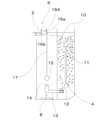
- FIG. 2 is a diagram for explaining the operation of the on-off valve mechanism shown in FIG. 1, and is a diagram showing the configuration of the main part in a state where one end opening of a communication passage is closed.
- FIG. 2 is a diagram for explaining the operation of the on-off valve mechanism shown in FIG. 1, and is a diagram showing the configuration of the main part in a state where one end opening of a communication passage is open.
- FIG. 11 is a diagram showing the configuration of a main part of a purification treatment device according to another embodiment of the present invention.
- FIG. 2 is a diagram for explaining the operation of a modified embodiment of the on-off valve mechanism shown in FIG.
- FIG. 1 is a diagram showing the configuration of the essential parts in a state where one end opening of the communication passage is closed.
- FIG. 6 is a diagram for explaining the operation of the on-off valve mechanism of FIG. 5, and is a diagram showing the configuration of the essential parts in a state where one end opening of the communication passage is open.
- FIG. 13 is a diagram for explaining the operation of another modified embodiment of the on-off valve mechanism shown in FIG. 1, and is a diagram showing the configuration of the essential parts in a state where one end opening of the communication passage is closed.
- FIG. 8 is an enlarged view for explaining the operation of another modified embodiment of the on-off valve mechanism of FIG. 7, showing a main portion in a state where one end opening of the communication passage is closed.
- FIG. 1 shows a purification treatment device 1 according to this embodiment.
- this purification treatment device 1 includes a stationary anaerobic tank 3 as a first anaerobic tank that performs a predetermined purification treatment on wastewater 2, a fluidized anaerobic tank 4 as a second anaerobic tank, a biological activated carbon tank 5, a solid-liquid separation tank 6, a disinfection tank 7, a storage tank 8, and an on-off valve mechanism 9.
- the wastewater 2 that flows into the internal space of the purification treatment device 1 passes through the above-mentioned multiple treatment tanks 3 to 7 in order from the upstream side, whereby the organic matter in the wastewater 2 is decomposed or removed, and the wastewater 2 is purified before being discharged.
- the stationary anaerobic tank 3 has a first anaerobic metabolism area 3a in which a large number of filter media (not shown) with anaerobic microorganisms attached thereto are held, and a second anaerobic metabolism area 3b located downstream of the first anaerobic metabolism area 3a and in which a large number of filter media with anaerobic microorganisms attached thereto are held, similar to the first anaerobic metabolism area 3a.
- a container such as a basket capable of holding and holding a large number of filter media is fixed to each of the anaerobic metabolism areas 3a and 3b, and each container is filled with a large number of filter media. Therefore, the movement of the large number of filter media held in each of the anaerobic metabolism areas 3a and 3b is restricted relative to each other (stationary state).
- the structure, material, size, etc. of the filter medium contained in the stationary anaerobic tank 3 are arbitrary, and it is possible to apply filter medium of known structure (for example, a mesh-like skeletal structure at a micro level, or a cylindrical shape at a macro level) and size.
- a fluidized anaerobic tank 4 is disposed downstream of the stationary anaerobic tank 3.
- This fluidized anaerobic tank 4 contains a large number of filter media 10 with anaerobic microorganisms attached thereto, and is configured so that these filter media 10 can flow inside the fluidized anaerobic tank 4 as the wastewater 2 flows into the fluidized anaerobic tank 4.
- a partition plate 11 extending in the vertical direction is provided inside the fluidized anaerobic tank 4.
- An inlet 12 for the wastewater 2 is provided at the bottom of the fluidized anaerobic tank 4 and faces upward.
- the wastewater 2 that flows into the fluidized anaerobic tank 4 through the inlet 12 flows upward along the partition plate 11, and then flows downward around the partition plate 11, creating a flow that circulates around the partition plate 11 (the flow shown by the two-dot chain line in Figure 1).
- the numerous filter media 10 contained in the fluidized anaerobic tank 4 can circulate around the partition plate 11 together with the wastewater 2 and become dispersed in the wastewater 2 in the fluidized anaerobic tank 4 (see FIG. 3).
- the structure, material, size, etc. of the filter medium 10 contained in the fluidized anaerobic tank 4 can be arbitrary, and it is possible to apply filter medium 10 of a known structure (for example, a mesh-like skeletal structure at a micro level, or a cylindrical shape at a macro level) and size.
- filter medium 10 of a known structure (for example, a mesh-like skeletal structure at a micro level, or a cylindrical shape at a macro level) and size.
- a filter medium 10 having a structure with excellent fluidity is desirable.
- the sizes of the filter media held in the first anaerobic metabolism area 3a decrease in the order of size to the filter media held in the second anaerobic metabolism area 3b, and the filter media 10 held in the flow anaerobic tank 4.
- a storage tank 8 is disposed upstream of the fluidized anaerobic tank 4 and downstream of the static anaerobic tank 3.
- the static anaerobic tank 3 and the storage tank 8 are connected so that the water level is always at the same height.
- the storage tank 8 and the fluidized anaerobic tank 4 are connected via a communication passage 13.
- An opening/closing valve mechanism 9 is provided in the storage tank 8, and one end opening 14 of the communication passage 13 located on the side of the storage tank 8 can be opened and closed by the opening/closing valve mechanism 9.
- the other end opening of the communication passage 13 serves as the inlet 12 for the wastewater 2 in the fluidized anaerobic tank 4.
- the opening/closing valve mechanism 9 is composed of a valve body 15, a floating body 16, and a connecting body 17.
- the valve body 15 is configured to be capable of closing one end opening 14 of the communication passage 13.
- the valve body 15 is spherical and configured to engage with the one end opening 14 as it descends and to be capable of releasing the engagement with the one end opening 14 as it ascends.
- the float 16 is configured to float on the surface of the wastewater 2 stored in the storage tank 8. More specifically, the float 16 is connected to the valve body 15 described above via a connector 17, and the volume (including shape) and density of the float 16 are set so that the float 16 always floats on the surface of the wastewater 2, regardless of fluctuations in the water level of the wastewater 2.
- the connecting body 17 may have any configuration as long as it can raise the valve body 15 while maintaining a constant distance from the floating body 16 when the floating body 16 rises with the rise in the water level.
- One example of the connecting body 17 is a string-like body obtained by twisting fibers.
- the biological activated carbon tank 5, solid-liquid separation tank 6, and disinfection tank 7 can have known configurations.
- the above-mentioned arrangement of the treatment tanks 3 to 7 is merely one example, and can of course be modified as appropriate depending on the application.
- the two anaerobic metabolic regions 3a, 3b provided in the stationary anaerobic tank 3 may be replaced with one or three or more anaerobic metabolic regions.
- the other treatment tanks 5 to 7 may be replaced with other types of treatment tanks, such as known biological treatment tanks, chemical treatment tanks, or physical treatment tanks.
- the number of treatment tanks 3 to 7 can be increased or decreased from the number (five) shown in FIG. 1.
- FIG. 2 shows the state of the on-off valve mechanism 9 when no new wastewater 2 is flowing into the storage tank 8.
- the buoyancy generated in the floating body 16, the weight of the valve body 15, and the sum of the water pressure acting in a direction pressing the valve body 15 downward are in balance.
- the valve body 15 is also fitted into one end opening 14 of the communication passage 13. Therefore, in this state, one end opening 14 of the communication passage 13 is blocked by the valve body 15, and no wastewater 2 flows from the storage tank 8 into the flowing anaerobic tank 4.
- the water level of the static anaerobic tank 3 located most upstream rises by the amount of the flowing wastewater 2
- the buoyancy of the floating body 16 increases by the amount of the rise.
- the wastewater 2 stored in the storage tank 8 rises to a predetermined water level and the buoyancy acting on the floating body 16 exceeds the sum of the weight of the valve body 15 and the water pressure, the valve body 15 starts to move upward together with the floating body 16 (see Figure 3).
- a fluidized anaerobic tank 4 in which a large number of filter media 10, which serve as carriers for anaerobic microorganisms, are accommodated in a fluidized state. Therefore, even though it is an anaerobic tank, the filter media 10 flows and disperses within the fluidized anaerobic tank 4, increasing the contact area between the filter media 10 and the wastewater 2. This increases the metabolic efficiency (decomposition efficiency) of the anaerobic microorganisms attached to the surface of the filter media 10, and effectively purifies the wastewater 2.
- the purification treatment device 1 is configured with only anaerobic tanks (static anaerobic tank 3, fluidized anaerobic tank 4) as the microbial treatment tanks, it is possible to ensure purification treatment capacity without increasing the number of anaerobic tanks or making the anaerobic tanks larger.
- a storage tank 8 for wastewater 2 is provided upstream of the fluidized anaerobic tank 4, and an opening/closing valve mechanism 9 is provided that can open/close one end opening 14 of a communication passage 13 that connects the storage tank 8 and the fluidized anaerobic tank 4 with a valve body 15.
- the opening/closing valve mechanism 9 By providing the opening/closing valve mechanism 9 in this manner, the inflow of wastewater 2 into the storage tank 8 can be used as a driving force to supply wastewater 2 to the fluidized anaerobic tank 4, so that a flow of wastewater 2 can be generated in the fluidized anaerobic tank 4 without using a power source such as a pump, and metabolic treatment can be effectively performed by the fluidized anaerobic tank 4.
- the purification treatment device 1 according to this embodiment can be used without problems even in areas where infrastructure such as electricity is not developed.
- the opening/closing valve mechanism 9 is composed of a valve body 15, a floating body 16 that floats on the water surface of the wastewater 2 stored in the storage tank 8, and a connecting body 17 that connects the floating body 16 and the valve body 15, and is configured so that the valve body 15 descends to engage with one end opening 14 that faces upward, and the valve body 15 rises and one end opening 14 can be opened when the wastewater 2 stored in the storage tank 8 rises to a predetermined water level.
- the opening/closing valve mechanism 9 By configuring the opening/closing valve mechanism 9 in this manner, when a certain amount of wastewater 2 flows into the purification treatment device 1, the buoyancy of the floating body 16 increases by the amount that the water level of the wastewater 2 in the storage tank 8 has risen, so that the buoyancy of the floating body 16 exceeds the sum of the weight of the valve body 15 and the water pressure, and the valve body 15 begins to move upward.
- the valve body 15 starts to move upward and separates from the one-end opening 14 of the communication passage 13
- water pressure acts on the valve body 15 from all directions, instantly increasing the difference between buoyancy and weight, and the wastewater 2 flows forcefully from the one-end opening 14 through the communication passage 13 into the fluidized anaerobic tank 4.
- This increases the fluidity of the filter medium 10, making it possible to further improve the metabolic efficiency of anaerobic microorganisms.
- valve body 15 is spherical, so when the valve body 15 rises together with the floating body 16 and then descends as the water level drops, the valve body 15 can be automatically guided to a horizontal position where it can fit into the one-end opening 14. This makes it possible to reliably fit the valve body 15 into the one-end opening 14 to close it, thereby enabling the above-mentioned wastewater 2 to flow stably into the flowing anaerobic tank 4.
- the valve body 15 can also be conically shaped so that it tapers downwards, guiding the fit into the one-end opening 14.
- the purification treatment device 1 according to the present invention is not limited to the above-mentioned exemplary configuration, and various modifications are possible within the scope of the present invention.
- FIG. 4 shows a diagram of the essential parts of the opening and closing valve mechanism 9 according to one such example (another embodiment of the present invention).
- the opening and closing valve mechanism 9 is composed of the valve body 15, the floating body 16, the connecting body 17, and a movement restriction part 18 that can restrict the horizontal movement of the valve body 15.
- three movement restriction parts 18 are arranged to extend in the vertical direction.
- FIG. 5 and 6 show modified forms of the float.
- the float 16A shown in Figs. 5 and 6 has a weight 16b attached at a position away from the connection position 16a between the connector 17 and the float 16A.
- the weight 16b By attaching the weight 16b to the float 16A, when the water level of the wastewater 2 rises from the state in which the valve body 15 closes the opening 14 at one end (Fig. 5), the weight 16b causes the float 16A to rotate around the connecting part 16a as shown in Fig. 6.
- the valve body 15 shown in Fig. 6 rises a greater distance than the valve body 15 shown in Fig. 3.
- a connecting portion 16a is provided on one end side of the floating body 16A, and a weight 16b is attached to the other end side of the floating body 16A.
- the on-off valve mechanism 9 is configured with a valve body 15 that can be raised and lowered, a floating body 16, and a connecting body 17 that connects the valve body 15 and the floating body 16.
- the on-off valve mechanism 9 can be configured in other ways.
- the on-off valve mechanism 9 may be configured with a valve body 15 and a biasing member 19 that biases the valve body 15 upward to a closed state, and the valve body 15 may be pressed against the biasing force of the biasing member 19 by the water pressure of the wastewater 2 stored in the storage tank 8 to open the one-end opening 14.
- the biasing member 19 is configured with a coil spring.
- the coil spring that constitutes the biasing member 19 has one end abutting against the valve body 15 and the other end abutting against the first inward flange 13a provided in the communication passage 13.
- the valve body 15 can abut against the second inward flange 13b provided at one end of the communication portion 13, and the second inward flange 13b forms the one-end opening 14.
- the one-end opening 14 is closed, and when the valve body 15 moves away from the second inward flange 13b, the one-end opening 14 opens as shown in FIG. 8.
- the on-off valve mechanism 9 that can open and close the valve body by increasing the water pressure
- the inflow of wastewater 2 into the storage tank 8 can be used as a driving force to open the valve body, so that the wastewater 2 can be supplied to the fluidized anaerobic tank 4 from one end opening 14 through the communication passage 13.
- the wastewater 2 can be sent to the fluidized anaerobic tank 4 using only the water pressure of the wastewater 2 and the biasing force of the biasing member, which also makes it possible to achieve the flow of the wastewater 2 and filter media 10 in the fluidized anaerobic tank 4 without any power or electricity.
- Reference Signs List 1 Purification treatment device 2 Wastewater 3 Stationary anaerobic tanks 3a, 3b Anaerobic metabolism area 4 Fluidized anaerobic tank 5 Biological activated carbon tank 6 Solid-liquid separation layer 7 Disinfection layer 8 Storage tank 9 Opening/closing valve mechanism 10 Filter material 11 Partition plate 12 Inlet 13 Communication passage 14 One end opening 15 Valve body 16 Floating body 16b Weight 17 Connecting body 18 Movement restriction part 19 Pressing member
Landscapes
- Life Sciences & Earth Sciences (AREA)
- Engineering & Computer Science (AREA)
- Microbiology (AREA)
- General Engineering & Computer Science (AREA)
- Biodiversity & Conservation Biology (AREA)
- Hydrology & Water Resources (AREA)
- Environmental & Geological Engineering (AREA)
- Water Supply & Treatment (AREA)
- Chemical & Material Sciences (AREA)
- Organic Chemistry (AREA)
- Mechanical Engineering (AREA)
- Purification Treatments By Anaerobic Or Anaerobic And Aerobic Bacteria Or Animals (AREA)
Priority Applications (1)
| Application Number | Priority Date | Filing Date | Title |
|---|---|---|---|
| JP2025520618A JPWO2024237281A1 (https=) | 2023-05-17 | 2024-05-15 |
Applications Claiming Priority (2)
| Application Number | Priority Date | Filing Date | Title |
|---|---|---|---|
| JP2023081916 | 2023-05-17 | ||
| JP2023-081916 | 2023-05-17 |
Publications (1)
| Publication Number | Publication Date |
|---|---|
| WO2024237281A1 true WO2024237281A1 (ja) | 2024-11-21 |
Family
ID=93519725
Family Applications (1)
| Application Number | Title | Priority Date | Filing Date |
|---|---|---|---|
| PCT/JP2024/017976 Ceased WO2024237281A1 (ja) | 2023-05-17 | 2024-05-15 | 浄化処理装置 |
Country Status (2)
| Country | Link |
|---|---|
| JP (1) | JPWO2024237281A1 (https=) |
| WO (1) | WO2024237281A1 (https=) |
Citations (6)
| Publication number | Priority date | Publication date | Assignee | Title |
|---|---|---|---|---|
| JPS5074756U (https=) * | 1973-11-08 | 1975-06-30 | ||
| JPS5310571U (https=) * | 1976-07-10 | 1978-01-28 | ||
| JPH02184395A (ja) * | 1989-01-06 | 1990-07-18 | Isao Ishii | 合併式浄化槽 |
| JPH0361998U (https=) * | 1989-10-24 | 1991-06-18 | ||
| JPH0824880A (ja) * | 1994-07-20 | 1996-01-30 | Miyoshi Shokai:Kk | 合併処理浄化槽 |
| JP2013075283A (ja) * | 2011-09-29 | 2013-04-25 | Kansai Kako Kk | 無動力無電源排水処理槽 |
-
2024
- 2024-05-15 JP JP2025520618A patent/JPWO2024237281A1/ja active Pending
- 2024-05-15 WO PCT/JP2024/017976 patent/WO2024237281A1/ja not_active Ceased
Patent Citations (6)
| Publication number | Priority date | Publication date | Assignee | Title |
|---|---|---|---|---|
| JPS5074756U (https=) * | 1973-11-08 | 1975-06-30 | ||
| JPS5310571U (https=) * | 1976-07-10 | 1978-01-28 | ||
| JPH02184395A (ja) * | 1989-01-06 | 1990-07-18 | Isao Ishii | 合併式浄化槽 |
| JPH0361998U (https=) * | 1989-10-24 | 1991-06-18 | ||
| JPH0824880A (ja) * | 1994-07-20 | 1996-01-30 | Miyoshi Shokai:Kk | 合併処理浄化槽 |
| JP2013075283A (ja) * | 2011-09-29 | 2013-04-25 | Kansai Kako Kk | 無動力無電源排水処理槽 |
Also Published As
| Publication number | Publication date |
|---|---|
| JPWO2024237281A1 (https=) | 2024-11-21 |
Similar Documents
| Publication | Publication Date | Title |
|---|---|---|
| US20090127188A1 (en) | Waste gas/wastewater treatment equipment and method of treating waste gas/wastewater | |
| KR101226547B1 (ko) | 선박용 오수처리장치 | |
| KR101638970B1 (ko) | 엠비비알을 이용한 선박용 오폐수 처리 장치 | |
| CN108002660B (zh) | 深度废水处理系统以及污水处理方法 | |
| KR101627642B1 (ko) | 고도수처리장치 | |
| KR101550216B1 (ko) | 중공사막모듈 및 이를 이용한 막분리 생물반응장치 | |
| KR20210091951A (ko) | 바이오플락 양식장용 자동 침전 순환 사육수조 | |
| CN208022860U (zh) | 深度废水处理系统 | |
| CN107986436B (zh) | 一种生物膜-膜生物耦合污水处理装置 | |
| WO2024237281A1 (ja) | 浄化処理装置 | |
| JP6001295B2 (ja) | 水処理装置 | |
| JP4017331B2 (ja) | 浄化槽 | |
| CN119018987A (zh) | 一种用于水处理的压电光催化曝气反应器 | |
| JP2006247469A (ja) | 汚水処理装置 | |
| JP4334387B2 (ja) | 排水処理装置 | |
| CN216946310U (zh) | 一种污水处理装置 | |
| KR100380321B1 (ko) | 유동상 및 고정상 접촉재를 이용한 고효율 정화처리 장치 | |
| KR100481821B1 (ko) | 기체용해 및 물질분리에 의한 수처리 장치 | |
| WO2019128474A1 (zh) | 深度污水处理系统以及污水处理方法 | |
| JP2007117908A (ja) | 浄化槽 | |
| JP5000594B2 (ja) | 合併処理浄化槽 | |
| KR102474264B1 (ko) | Uv 오존 순환형 산화반응 공정과 세라믹 분리막의 막여과 공정이 결합된 일체형 양방향 수처리 장치 및 그 방법 | |
| JP4481066B2 (ja) | 汚水浄化槽及び汚水浄化槽の脱臭方法 | |
| CN208022775U (zh) | 生物膜-膜生物耦合污水处理装置 | |
| KR200383134Y1 (ko) | 단독정화조용 수처리장치 |
Legal Events
| Date | Code | Title | Description |
|---|---|---|---|
| 121 | Ep: the epo has been informed by wipo that ep was designated in this application |
Ref document number: 24807232 Country of ref document: EP Kind code of ref document: A1 |
|
| ENP | Entry into the national phase |
Ref document number: 2025520618 Country of ref document: JP Kind code of ref document: A |
|
| WWE | Wipo information: entry into national phase |
Ref document number: 2025520618 Country of ref document: JP |
|
| NENP | Non-entry into the national phase |
Ref country code: DE |