WO2024237232A1 - 発泡性接着シートおよび物品の製造方法 - Google Patents
発泡性接着シートおよび物品の製造方法 Download PDFInfo
- Publication number
- WO2024237232A1 WO2024237232A1 PCT/JP2024/017640 JP2024017640W WO2024237232A1 WO 2024237232 A1 WO2024237232 A1 WO 2024237232A1 JP 2024017640 W JP2024017640 W JP 2024017640W WO 2024237232 A1 WO2024237232 A1 WO 2024237232A1
- Authority
- WO
- WIPO (PCT)
- Prior art keywords
- adhesive layer
- adhesive
- curing
- foaming
- foamable
- Prior art date
- Legal status (The legal status is an assumption and is not a legal conclusion. Google has not performed a legal analysis and makes no representation as to the accuracy of the status listed.)
- Ceased
Links
Images
Classifications
-
- B—PERFORMING OPERATIONS; TRANSPORTING
- B32—LAYERED PRODUCTS
- B32B—LAYERED PRODUCTS, i.e. PRODUCTS BUILT-UP OF STRATA OF FLAT OR NON-FLAT, e.g. CELLULAR OR HONEYCOMB, FORM
- B32B5/00—Layered products characterised by the non- homogeneity or physical structure, i.e. comprising a fibrous, filamentary, particulate or foam layer; Layered products characterised by having a layer differing constitutionally or physically in different parts
- B32B5/18—Layered products characterised by the non- homogeneity or physical structure, i.e. comprising a fibrous, filamentary, particulate or foam layer; Layered products characterised by having a layer differing constitutionally or physically in different parts characterised by features of a layer of foamed material
-
- C—CHEMISTRY; METALLURGY
- C09—DYES; PAINTS; POLISHES; NATURAL RESINS; ADHESIVES; COMPOSITIONS NOT OTHERWISE PROVIDED FOR; APPLICATIONS OF MATERIALS NOT OTHERWISE PROVIDED FOR
- C09J—ADHESIVES; NON-MECHANICAL ASPECTS OF ADHESIVE PROCESSES IN GENERAL; ADHESIVE PROCESSES NOT PROVIDED FOR ELSEWHERE; USE OF MATERIALS AS ADHESIVES
- C09J201/00—Adhesives based on unspecified macromolecular compounds
-
- C—CHEMISTRY; METALLURGY
- C09—DYES; PAINTS; POLISHES; NATURAL RESINS; ADHESIVES; COMPOSITIONS NOT OTHERWISE PROVIDED FOR; APPLICATIONS OF MATERIALS NOT OTHERWISE PROVIDED FOR
- C09J—ADHESIVES; NON-MECHANICAL ASPECTS OF ADHESIVE PROCESSES IN GENERAL; ADHESIVE PROCESSES NOT PROVIDED FOR ELSEWHERE; USE OF MATERIALS AS ADHESIVES
- C09J5/00—Adhesive processes in general; Adhesive processes not provided for elsewhere, e.g. relating to primers
-
- C—CHEMISTRY; METALLURGY
- C09—DYES; PAINTS; POLISHES; NATURAL RESINS; ADHESIVES; COMPOSITIONS NOT OTHERWISE PROVIDED FOR; APPLICATIONS OF MATERIALS NOT OTHERWISE PROVIDED FOR
- C09J—ADHESIVES; NON-MECHANICAL ASPECTS OF ADHESIVE PROCESSES IN GENERAL; ADHESIVE PROCESSES NOT PROVIDED FOR ELSEWHERE; USE OF MATERIALS AS ADHESIVES
- C09J7/00—Adhesives in the form of films or foils
- C09J7/30—Adhesives in the form of films or foils characterised by the adhesive composition
Definitions
- This disclosure relates to a foamable adhesive sheet and a method for manufacturing an article using the same.
- Adhesives that bond two components together are used in a variety of fields, and many bonding methods are known.
- a foamable adhesive sheet is known that has adhesive layers on both sides of a substrate.
- one adhesive layer be a foamed layer that contains a foaming agent
- the other adhesive layer be a non-foamed layer that does not contain a foaming agent (see, for example, Patent Documents 1 and 2).
- a method of bonding two components using a foamable adhesive sheet for example, a method of placing a foamable adhesive sheet between two components and then foaming and curing the foamable adhesive sheet to bond the two components can be mentioned.
- a foamable adhesive sheet when adhesive layers are placed on both sides of a substrate, one adhesive layer is a foamed layer and the other adhesive layer is a non-foamed layer, the hardness of the adhesive layer after curing varies depending on whether or not it contains a foaming agent. A non-foamed adhesive layer tends to become hard and brittle when cured. Therefore, after the foamable adhesive sheet is foamed and cured, the second adhesive layer after curing may peel off from the substrate.
- the second adhesive layer after curing peels off from the substrate and becomes a foreign object, and the foreign object adheres to a component, it may lead to product failure, or if the foamable adhesive sheet has insulating properties, it may cause poor insulation.
- a shear stress is applied after the foamable adhesive sheet is foamed and cured, an excessive load may be applied to layers other than the second adhesive layer, leading to destruction.
- the present disclosure has been made in consideration of the above-mentioned circumstances, and has as its main objective the provision of a foamable adhesive sheet in which the second adhesive layer has good adhesion to the substrate and durability after curing.
- One embodiment of the present disclosure provides a foamable adhesive sheet having a first adhesive layer, a substrate, and a second adhesive layer in this order, the first adhesive layer containing a first curable adhesive and a foaming agent, the second adhesive layer containing a second curable adhesive and no foaming agent, and when a tensile shear adhesive strength test method is performed on the foamable adhesive sheet after foaming and curing, the failure mode is cohesive failure of the first adhesive layer after foaming and curing, and when a tensile shear adhesive strength test method is performed on the second adhesive layer after curing, the slope of the approximation line in the section from 3% strain to 5% strain in the stress-strain curve obtained is 0.20 MPa or less.
- Another embodiment of the present disclosure provides a method for manufacturing an article, comprising a step of placing the foamable adhesive sheet between a first member and a second member, and a step of foaming and curing the foamable adhesive sheet to bond the first member and the second member.
- the present disclosure has the effect of providing a foamable adhesive sheet in which the second adhesive layer has good adhesion to the substrate after curing, and has good durability.
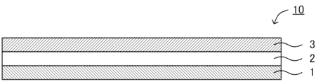
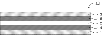
- FIG. 1 is a schematic cross-sectional view showing an example of a foamable adhesive sheet according to the present disclosure.
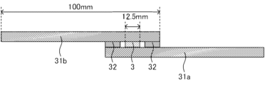
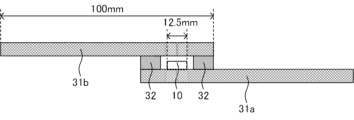
- FIG. 2 is a schematic cross-sectional view illustrating a method for testing the tensile shear adhesive strength of the second adhesive layer after curing.
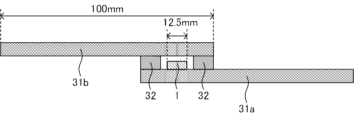
- FIG. 2 is a schematic cross-sectional view illustrating a method for testing the tensile shear adhesive strength of the first adhesive layer after foaming and curing.
- FIG. 2 is a schematic cross-sectional view illustrating a method for testing the tensile shear adhesive strength of the first adhesive layer after foaming and curing.
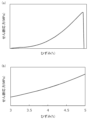
- 1 is a graph illustrating an example of a stress-strain curve.
- FIG. 1 is a graph illustrating an example of a stress-strain curve.
- FIG. 2 is a schematic cross-sectional view illustrating a method for testing the tensile shear adhesive strength of a foamable adhesive sheet after foaming and curing.
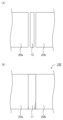
- FIG. 2 is a schematic cross-sectional view showing another example of a foamable adhesive sheet according to the present disclosure.
- FIG. 2 is a schematic cross-sectional view showing an example of a method for producing an article according to the present disclosure.
- the term “above” or “below” includes both cases in which another component is placed directly above or below a certain component so as to be in contact with the component, and cases in which another component is placed above or below a certain component with another component in between, unless otherwise specified.
- the term “on the surface side” or “on the surface” includes both cases in which another component is placed directly above or below a certain component so as to be in contact with the component, and cases in which another component is placed above or below a certain component with another component in between, unless otherwise specified.
- sheet also includes materials called “films.”
- films also includes materials called “sheets.”
- numerical ranges in this specification are average value ranges.
- the foamable adhesive sheet of the present disclosure has a first adhesive layer, a substrate, and a second adhesive layer in this order, the first adhesive layer contains a first curable adhesive and a foaming agent, the second adhesive layer contains a second curable adhesive and does not contain a foaming agent, the failure mode when the foamable adhesive sheet after foaming and curing is subjected to a tensile shear adhesive strength test method is cohesive failure of the first adhesive layer after foaming and curing, and the slope of the approximation line in the section from strain 3% to strain 5% in the stress-strain curve obtained when the tensile shear adhesive strength test method is performed on the second adhesive layer after curing is 0.20 MPa or less.
- the foamable adhesive sheet 10 has a first adhesive layer 1, a substrate 2, and a second adhesive layer 3, in this order.
- the first adhesive layer 1 contains a first curable adhesive and a foaming agent.
- the second adhesive layer 3 contains a second curable adhesive, but does not contain a foaming agent.
- the failure mode is cohesive failure of the first adhesive layer after foaming and curing.
- the slope of the approximation line in the section from 3% strain to 5% strain is within a predetermined range.
- the first adhesive layer contains a foaming agent
- the foamable adhesive sheet when a foamable adhesive sheet is used to bond two components, the foamable adhesive sheet is foamed and cured, and the gap between the two components is filled with the foamable adhesive sheet after foaming and curing, thereby bonding the two components. Therefore, the thickness of the foamable adhesive sheet before foaming and curing can be made thinner than the gap between the two components, so that the insertability of the foamable adhesive sheet is improved.
- the second adhesive layer does not contain a foaming agent, the surface of the foamable adhesive sheet on the second adhesive layer side does not have unevenness due to the foaming agent.
- the insertability of the foamable adhesive sheet can be improved.
- the foamable adhesive sheet can be smoothly inserted into the gap between two components.
- the other component can be smoothly inserted into the gap.
- the other component and the foamable adhesive sheet can be smoothly inserted into the hole or groove of one component.
- the surface of the foamable adhesive sheet facing the second adhesive layer can be caught by the component, preventing the foaming agent from falling off and the second adhesive layer from being scraped off. This improves the abrasion resistance of the second adhesive layer.
- the first adhesive layer contains a foaming agent
- only one of the two adhesive layers contains a foaming agent, and therefore, compared to when both adhesive layers contain a foaming agent, it is possible to prevent the surface of the foamable adhesive sheet from getting caught on a member.
- by arranging the foamable adhesive sheet so that the surface on the first adhesive layer side faces the first member and the surface on the second adhesive layer side faces the second member it is possible to prevent the surface on the second adhesive layer side of the foamable adhesive sheet from getting caught on the second member when inserting the second member into the gap after placing the foamable adhesive sheet in a hole or groove of the first member.
- the foamable adhesive sheet when inserting the second member and the foamable adhesive sheet into a hole or groove in the first member, by arranging the foamable adhesive sheet so that the surface of the foamable adhesive sheet facing the first adhesive layer faces the second member and the surface of the foamable adhesive sheet facing the second adhesive layer faces the first member, it is possible to prevent the surface of the foamable adhesive sheet facing the second adhesive layer from getting caught on the first member when the second member and the foamable adhesive sheet are inserted into the hole or groove in the first member.
- the second adhesive layer since the second adhesive layer does not contain a foaming agent, the second adhesive layer after curing does not have bubbles due to the foaming agent. In other words, after the foamable adhesive sheet is foamed and cured, the surface on the side of the cured second adhesive layer does not have unevenness due to bubbles. Therefore, when two components are bonded using a foamable adhesive sheet, the contact area between the cured second adhesive layer and the components is large. This improves the thermal conductivity between the two components. For example, when a foamable adhesive sheet is used to bond a stator core and a coil in a rotor stator, the thermal conductivity between the stator core and the coil can be increased, and heat dissipation can be improved.
- the second adhesive layer after curing tends to be harder and more brittle than the first adhesive layer after foaming and curing. Therefore, after foaming and curing of the foamable adhesive sheet, the second adhesive layer after curing is likely to peel off from the substrate, which may cause foreign matter. In addition, after foaming and curing of the foamable adhesive sheet, if shear stress is applied, excessive load is applied to layers other than the second adhesive layer, which may lead to destruction.
- the slope of the approximate straight line is a predetermined value or less, so that the second adhesive layer after curing has an appropriate hardness. Therefore, the difference between the hardness of the second adhesive layer after curing and the hardness of the first adhesive layer after foaming and curing can be reduced. Therefore, after the foamable adhesive sheet has been foamed and cured, the adhesion of the cured second adhesive layer to the substrate can be increased, thereby preventing the generation of foreign matter. In addition, after the foamable adhesive sheet has been foamed and cured, when shear stress is applied, excessive load on layers other than the second adhesive layer can be prevented, improving the durability of the foamable adhesive sheet after foaming and curing.
- the failure mode when the tensile shear adhesive strength test method is performed on the foamable adhesive sheet is cohesive failure of the first adhesive layer after foaming and curing. Therefore, it can be said that the adhesiveness of the second adhesive layer after curing is high. Furthermore, the adhesiveness of the first adhesive layer after foaming and curing is also high.
- tensile shear adhesive strength testing There are various known methods for testing adhesive strength, including tensile shear adhesive strength testing, tensile adhesive strength testing, peel adhesive strength testing, and bending adhesive strength testing, but generally, tensile shear adhesive strength is often used to evaluate adhesives. Furthermore, when two components are bonded together, the joint is subjected to stresses such as tensile stress, compressive stress, and shear stress, but when one component is bonded and fixed to a hole or groove in the other component, it is believed that the joint is primarily subjected to shear stress. For this reason, in this disclosure, the tensile shear adhesive strength testing method is used to evaluate physical properties.
- the slope of the approximation line in the section from strain 3% to strain 5% is 0.20 MPa or less, may be 0.15 MPa or less, or may be 0.10 MPa or less.
- the second adhesive layer after curing has an appropriate hardness. Therefore, the difference between the hardness of the second adhesive layer after curing and the hardness of the first adhesive layer after foaming and curing can be reduced.
- the second adhesive layer after curing is suppressed from peeling off from the substrate, thereby suppressing the generation of foreign matter.
- the above-mentioned slope is, for example, 0.05 MPa or more, may be 0.07 MPa or more, or may be 0.10 MPa or more. If the gradient is within the above range, the second adhesive layer after curing has an appropriate hardness, and therefore the adhesiveness of the second adhesive layer after curing is high. Specifically, the gradient may be 0.05 MPa or more and 0.20 MPa or less, or 0.07 MPa or more and 0.15 MPa or less.
- the difference between the slope of the approximate straight line in the section from 3% to 5% strain in the stress-strain curve obtained when the tensile shear bond strength test method is performed on the first adhesive layer after foaming and curing and the slope of the approximate straight line in the section from 3% to 5% strain in the stress-strain curve obtained when the tensile shear bond strength test method is performed on the second adhesive layer after curing is preferably 0.20 MPa or less, may be 0.15 MPa or less, or may be 0.10 MPa or less.
- the difference in the slope is within the above range, the difference in hardness between the second adhesive layer after curing and the first adhesive layer after foaming and curing becomes small.
- the difference in the slope is, for example, 0.05 MPa or more, may be 0.07 MPa or more, or may be 0.10 MPa or more. If the difference in the slope is within the above range, the second adhesive layer after curing has an appropriate hardness, and therefore the adhesiveness of the second adhesive layer after curing is high. Specifically, the difference in the slope is 0.05 MPa or more and 0.20 MPa or less, and may be 0.07 MPa or more and 0.15 MPa or less.
- the tensile shear adhesive strength test method is performed according to JIS K6850:1999, which corresponds to ISO 4587, and is performed by the following method.
- a second adhesive layer measuring 12.5 mm x 25 mm is prepared.
- the adhesive composition used in the second adhesive layer of the foamable adhesive sheet or its composition is known, the second adhesive layer is formed using that adhesive composition or by preparing an adhesive composition with that composition.
- the composition of the second adhesive layer of the foamable adhesive sheet may also be analyzed, and an adhesive composition with that composition may be prepared to form the second adhesive layer.
- a known method may be used as a method for analyzing the composition of the second adhesive layer.
- the thickness of the second adhesive layer is the same as that of the second adhesive layer of the foamable adhesive sheet.
- two metal plates 31a and 31b with a thickness of 1.6 mm, a width of 25 mm, and a length of 100 mm are prepared.
- cold-rolled steel plate SPCC-SD can be used as the metal plate.
- a spacer 32 is placed at one end of one metal plate 31a with a predetermined interval. The thickness of the spacer 32 is set to be equal to or greater than the thickness of the second adhesive layer minus 15 ⁇ m and equal to or less than the thickness of the second adhesive layer.
- the thickness of the spacer 32 is adjusted by, for example, stacking multiple sheets of Kapton adhesive tape manufactured by Teraoka Seisakusho Co., Ltd.
- the second adhesive layer 3 is placed between the spacers 32, and the other metal plate 31b is placed so that one end overlaps, and fixed with a clip or an adhesive tape such as Kapton tape to obtain a test piece.
- the second adhesive layer of the test piece is cured.
- the curing conditions are appropriately adjusted according to the second curable adhesive contained in the second adhesive layer.
- the tensile shear adhesive strength test method is performed on the test piece after curing in accordance with JIS K6850:1999.
- the measurement conditions are tensile speed: 10 mm/min, grip distance: 100 mm, temperature: normal temperature (23°C), and humidity: 50% RH.
- a tensile tester for example, Tensilon RTF1350 manufactured by A&D Co., Ltd. can be used.
- the tensile shear adhesive strength test method is performed according to JIS K6850:1999, which corresponds to ISO 4587, and is performed by the following method.
- a first adhesive layer having a size of 12.5 mm x 25 mm is prepared.
- the adhesive composition used in the first adhesive layer of the foamable adhesive sheet or its composition is known, the first adhesive layer is formed using that adhesive composition or by preparing an adhesive composition with that composition.
- the composition of the first adhesive layer of the foamable adhesive sheet may be analyzed, and an adhesive composition with that composition may be prepared to form the first adhesive layer.
- a known method may be applied as a method for analyzing the composition of the first adhesive layer.
- the thickness of the first adhesive layer is the same as that of the first adhesive layer of the foamable adhesive sheet. Also, as shown in FIG. 3, two metal plates 31a and 31b having a thickness of 1.6 mm, a width of 25 mm, and a length of 100 mm are prepared. For example, cold-rolled steel plate SPCC-SD can be used as the metal plate. A spacer 32 is disposed at a predetermined interval at one end of one of the metal plates 31a. The thickness of the spacer 32 is appropriately set according to the foaming ratio of the first adhesive layer. For example, as shown in FIG.
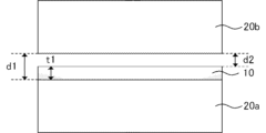
- the foamable adhesive sheet 10 is foamed and cured (not shown) to bond the first member 20a and the second member 20b. If the distance d1 between the first member 20a and the second member 20b is known, the gap d2 after disposing the foamable adhesive sheet 10 between the first member 20a and the second member 20b is first obtained. The gap d2 is obtained by subtracting the thickness t1 of the foamable adhesive sheet 10 from the distance d1. Next, the thickness of the spacer 32 is set based on the thickness of the first adhesive layer and the gap d2. The thickness of the spacer 32 is obtained by adding the thickness of the first adhesive layer and the gap d2.
- the thickness of the spacer 32 may be within ⁇ 5% of the sum of the thickness of the first adhesive layer and the gap d2.
- the expansion ratio of the first adhesive layer is first obtained.
- the expansion ratio here refers to the expansion ratio when the first adhesive layer is foamed and cured without being sandwiched between any members.
- the expansion ratio of the first adhesive layer can be obtained by foaming and curing the foamable adhesive sheet without being sandwiched between any members.
- the thickness of the spacer 32 is (thickness of the first adhesive layer) ⁇ (expansion ratio of the first adhesive layer) ⁇ 0.3 or more and (thickness of the first adhesive layer) ⁇ (expansion ratio of the first adhesive layer) ⁇ 0.8 or less.
- the thickness of the spacer 32 is equal to or more than the thickness of the first adhesive layer.
- the thickness of the spacer 32 is adjusted by stacking multiple sheets of Kapton adhesive tape manufactured by Teraoka Seisakusho Co., Ltd. Next, the first adhesive layer 1 is placed between the spacers 32, and the other metal plate 31b is placed so that one end overlaps, and fixed with a clip or an adhesive tape such as Kapton tape to obtain a test piece.
- the first adhesive layer of the test piece is foamed and cured.
- the foaming and curing conditions are appropriately adjusted depending on the first curable adhesive and the foaming agent contained in the first adhesive layer.
- the test piece after foaming and curing is subjected to a tensile shear bond strength test method in accordance with JIS K6850:1999.
- the measurement conditions are a tensile speed of 10 mm/min, a gripping distance of 100 mm, a temperature of room temperature (23°C), and a humidity of 50% RH.
- a Tensilon RTF1350 manufactured by A&D Co., Ltd. can be used as a tensile tester.
- the stress-strain curve plots the relationship between shear stress and strain obtained in the above-mentioned tensile shear bond strength test method, for example as shown in Figures 5(a) and (b), with strain (%) on the horizontal axis and shear stress (MPa) on the vertical axis.
- the strain is the increase in the distance between the gripping tools divided by the length of the first adhesive layer or the second adhesive layer, i.e., 12.5 mm.
- Figure 5(b) is an enlarged view of Figure 5(a).
- the approximation line for the section from 3% strain to 5% strain is obtained by linearly approximating the curve for the section from 3% strain to 5% strain using the least squares method. The slope of the approximation line is then determined. The above tensile shear bond strength test method is performed three times, and the average value of the three values is used as the slope of the approximation line.
- the initial slope is the slope in the elastic region. Therefore, in this disclosure, the initial slope is used. Also, in the stress-strain curve, shear stress tends not to be stable in the section below 3% strain. Therefore, in this disclosure, the slope of the section from 3% strain to 5% strain is used as the initial slope.
- Methods for controlling the slope of the approximate straight line for the cured second adhesive layer include, for example, adjusting the composition of the second adhesive layer and adjusting the drying conditions when forming the second adhesive layer.
- the hardness of the second adhesive layer after curing tends to be smaller and the slope of the above approximate straight line tends to be smaller.
- a second adhesive layer containing an epoxy resin and a curing agent if the number of functional groups of the epoxy resin is the same, by reducing the molecular weight of the epoxy resin, the hardness of the second adhesive layer after curing tends to be smaller and the slope of the above approximate straight line tends to be smaller.
- a second adhesive layer containing an epoxy resin and a curing agent by reducing the content of polyfunctional epoxy resin, the crosslink density after curing decreases, so the hardness of the second adhesive layer after curing tends to be smaller and the slope of the above approximate straight line tends to be smaller.
- the failure mode is cohesive failure of the first adhesive layer after foaming and curing. If the failure mode is cohesive failure of the first adhesive layer after foaming and curing, it can be said that the second adhesive layer after curing has a higher strength than the first adhesive layer after foaming and curing.
- the tensile shear adhesive strength test method for the foamed and cured foamed adhesive sheet is performed in accordance with JIS K6850:1999, which corresponds to ISO 4587, as follows.
- a foamed adhesive sheet measuring 12.5 mm x 25 mm is prepared.
- two metal plates 31a and 31b each having a thickness of 1.6 mm, width of 25 mm and length of 100 mm are prepared.
- Cold-rolled steel plate SPCC-SD for example, can be used as the metal plate.
- a spacer 32 is placed at one end of one of the metal plates 31a with a predetermined distance between them. The thickness of the spacer 32 is set appropriately according to the foaming ratio of the first adhesive layer. For example, as shown in FIG.
- the foamable adhesive sheet 10 is foamed and cured (not shown) to bond the first member 20a and the second member 20b.
- the thickness of the spacer 32 is set to the above distance d1.
- the thickness of the spacer 32 may be within the above distance d1 ⁇ 5%.
- the foaming ratio here refers to the foaming ratio when the first adhesive layer is foamed and cured without being sandwiched between any members.
- the foaming ratio of the first adhesive layer can be obtained by foaming and curing the foamable adhesive sheet without being sandwiched between any members.
- the thickness of the spacer 32 is ⁇ (thickness of the foamable adhesive sheet)-(thickness of the first adhesive layer) ⁇ +(thickness of the first adhesive layer) ⁇ (expansion ratio of the first adhesive layer) ⁇ 0.3 or more, and ⁇ (thickness of the foamable adhesive sheet)-(thickness of the first adhesive layer) ⁇ +(thickness of the first adhesive layer) ⁇ (expansion ratio of the first adhesive layer) ⁇ 0.8 or less.
- the thickness of the spacer 32 is equal to or more than the thickness of the foamable adhesive sheet.
- the thickness of the spacer 32 is adjusted by stacking a plurality of Kapton adhesive tapes manufactured by Teraoka Seisakusho Co., Ltd.
- the foamable adhesive sheet 10 is placed between the spacers 32, and the other metal plate 31b is placed so that one tip overlaps, and fixed with a clip or an adhesive tape such as Kapton tape to obtain a test piece.
- the first adhesive layer of the test piece is foamed and cured, and the second adhesive layer is cured.
- the foaming and curing conditions are appropriately adjusted according to the first curable adhesive and foaming agent contained in the first adhesive layer and the second curable adhesive contained in the second adhesive layer.
- test piece after foaming and curing is subjected to a tensile shear adhesive strength test method in accordance with JIS K6850:1999.
- the measurement conditions are a tensile speed of 10 mm/min, temperature at room temperature (23°C), and humidity of 50% RH.
- a Tensilon RTF1350 manufactured by A&D Co., Ltd. can be used as a tensile tester.
- the fracture surface of the test piece is visually observed.
- the failure mode being cohesive failure of the first adhesive layer after foaming and hardening means that the rate of cohesive failure inside the first adhesive layer after foaming and hardening is 90% or more.
- the rate of cohesive failure is the ratio of the area of the cohesive failure part inside the first adhesive layer to the total adhesive area.
- the above tensile shear adhesive strength test method is performed three times, and the above cohesive failure rate is used as the average value of the three values.
- the foamable adhesive sheet of the present disclosure preferably has high adhesiveness after foaming and curing.
- the shear adhesive strength may be, for example, 2.1 MPa or more, or 2.3 MPa or more at 23°C.
- the shear adhesive strength may be, for example, 0.27 MPa or more, 0.55 MPa or more, or 0.58 MPa or more at 200°C.
- a high-strength acrylic foam adhesive tape that does not require heating has a shear adhesive strength of about 1 MPa or more and 2 MPa or less at room temperature, and is not heat resistant at 200°C. Therefore, if the shear adhesive strength is in the above range at 23°C, it has an advantage in terms of strength. Also, if the shear adhesive strength is in the above range at 200°C, it can be applied to applications that require heat resistance around automobile engines or similar.
- the shear adhesive strength of the foamable adhesive sheet after foaming and curing is measured using the tensile shear adhesive strength test method described above.
- the shear adhesive strength is the maximum shear stress at break.
- the foamable adhesive sheet of the present disclosure preferably has good shape retention.
- the bending moment based on JIS P8125-2:2017 corresponding to ISO 2493 is, for example, 3 gf cm or more, and may be 5 gf cm or more.
- the bending moment may be, for example, less than 40 gf cm, and may be less than 30 gf cm.
- the inventors of the present disclosure have found that shape retention can be guaranteed by devising the shape, and that a high bending moment has other disadvantages, so that in consideration of other characteristics, it is preferable that the bending moment be within the above range.
- the bending moment is smaller than the above range, it may be difficult to maintain the shape even by devising folding or the like. Also, if the bending moment is larger than the above range, the shape returns to its original shape after folding, so it is necessary to heat the sheet during folding or to make a crease at the fold. Heating the sheet reduces its lifespan, and striations can reduce the insulation of that area.
- the electrical insulation after foaming and curing is high.
- the breakdown voltage based on JIS C2107:2011, which corresponds to IEC 60454-2, is, for example, preferably 1 kV or more, and more preferably 3 kV or more. With the breakdown voltage in the above range, application to rust prevention and around copper wires becomes possible.
- the thermal conductivity after foaming and curing is, for example, 0.1 W/mK or more, and more preferably 0.15 W/mK or more. With the thermal conductivity in the above range, it is possible to miniaturize parts and promote the curing reaction when heated.
- the first adhesive layer in the present disclosure is disposed on one surface of the substrate and contains a first curable adhesive and a foaming agent.
- the first adhesive layer in the present disclosure is preferably substantially non-adhesive.
- the tack of the first adhesive layer is preferably less than 0.1 N, and may be 0.05 N or less, or may be 0.02 N or less.
- the first adhesive layer becomes substantially non-adhesive (tack-free).
- the slipperiness of the first adhesive layer is improved, and the insertability of the foamable adhesive sheet can be improved.
- the tack of the first adhesive layer is measured by a probe tack test. Specifically, a cylindrical stainless steel probe with a diameter of 5 mm is pressed against the surface of the first adhesive layer of the foamable adhesive sheet at a temperature of 23 ⁇ 5°C and a humidity of 50 ⁇ 30% RH with a load of 0.1 N and a speed of 30 mm/min, and after holding for 1.0 second, it is peeled off at a speed of 30 mm/min and the load at the time of peeling is measured. This measurement is carried out five times, and the average value is taken as the tack. For example, a tack testing machine "TAC-II" manufactured by RHESCA can be used as the probe tack tester.
- TAC-II tack testing machine manufactured by RHESCA
- an example of a method for controlling the tackiness of the first adhesive layer is a method for adjusting the composition of the first adhesive layer.
- the tackiness of the first adhesive layer can be reduced by using an epoxy resin that is solid at room temperature or a curing agent that is solid at room temperature in the first adhesive layer containing an epoxy resin and a curing agent.
- the tackiness of the first adhesive layer can be reduced by including an epoxy resin with a high softening temperature or an epoxy resin with a large weight average molecular weight in the first adhesive layer containing an epoxy resin and a curing agent.
- the tackiness of the first adhesive layer can be reduced by including multiple types of epoxy resins with different softening temperatures in the first adhesive layer, that is, by including one epoxy resin and another epoxy resin whose softening temperature is 25°C or higher and 10°C or higher than the softening temperature of the one epoxy resin in the first adhesive layer.
- the first adhesive layer may contain multiple types of epoxy resins with different weight average molecular weights, that is, the first adhesive layer may contain one epoxy resin and another epoxy resin having a weight average molecular weight of 370 or more and 300 or more greater than the weight average molecular weight of the first epoxy resin, thereby reducing the tack of the first adhesive layer.
- the first adhesive layer containing an epoxy resin and a curing agent may contain a first epoxy resin having a low softening temperature and a low molecular weight, and a second epoxy resin having a high softening temperature and a high molecular weight, as described below, to reduce the tack of the first adhesive layer.
- the first adhesive layer containing an epoxy resin and a curing agent may contain an acrylic resin that is compatible with the epoxy resin, as described below, to reduce the tack of the first adhesive layer.
- non-tacky is generally used to mean low adhesive strength.
- substantially non-tacky means that the tack is less than 0.1 N.
- Adhesion is a concept that is included in “bonding.” The two are sometimes distinguished in that while adhesion is used to mean a temporary adhesive phenomenon, adhesion is used to mean a substantially permanent adhesive phenomenon (Iwanami Shoten Dictionary of Physics and Chemistry, 5th Edition). "Adhesiveness” and “adhesive strength” refer to the property of adhesion through pressure and the adhesive strength at that time.
- adheresion of the adhesive layer and “adhesive strength of the adhesive layer” refer to the adhesion and adhesive strength of the adhesive layer before curing.
- adhesion of the adhesive layer and “adhesive strength of the adhesive layer” refer to the adhesion and adhesive strength of the adhesive layer after curing.
- the first curable adhesive contained in the first adhesive layer in the present disclosure may be a curable adhesive generally used in the adhesive layer of an adhesive sheet.
- the first curable adhesive include heat-curable adhesives and light-curable adhesives. Among these, heat-curable adhesives are preferred. Heat-curable adhesives can be applied even when the member does not have transparency, such as a metal member.
- first curing adhesive examples include epoxy resin adhesives, acrylic resin adhesives, phenolic resin adhesives, unsaturated polyester resin adhesives, alkyd resin adhesives, urethane resin adhesives, and thermosetting polyimide resin adhesives.
- the first curable adhesive is preferably an epoxy resin adhesive. That is, the first curable adhesive preferably contains an epoxy resin and a curing agent.
- epoxy resin adhesives produce hard and tough cured films, making them suitable for bonding components made of hard materials such as metal or glass components.
- epoxy resin adhesives generally have excellent heat resistance, insulating properties, chemical resistance, etc., and have little shrinkage on curing, making them suitable for a wide range of applications.
- the first curable adhesive is an epoxy resin-based adhesive
- the first curable adhesive further contains an acrylic resin that is compatible with the epoxy resin.
- the toughness of the first adhesive layer can be increased. This can improve the adhesion after foaming and curing.
- the first curable adhesive is an epoxy resin adhesive.
- Epoxy resin in the present disclosure is a compound that has at least one epoxy group or glycidyl group and is cured by a crosslinking polymerization reaction in combination with a curing agent.
- the epoxy resin also includes a monomer having at least one epoxy group or glycidyl group.
- the curable adhesive preferably contains, as the epoxy resin, a first epoxy resin having a softening temperature of 50°C or higher and an epoxy equivalent of 5000 g/eq or lower, and a second epoxy resin having a softening temperature higher than that of the first epoxy resin and a weight average molecular weight of 20,000 or higher.
- low molecular weight (low epoxy equivalent) epoxy resin For example, if you only want to improve the adhesiveness after foaming and curing, it is more effective to use a low molecular weight (low epoxy equivalent) epoxy resin than a high molecular weight (high epoxy equivalent) epoxy resin. However, if a low molecular weight (low epoxy equivalent) epoxy resin is used, for example when the adhesive sheet is wound into a roll, the low molecular weight (low epoxy equivalent) epoxy resins will assimilate with each other, making it more likely to cause blocking.
- the first epoxy resin melts rapidly and changes to a low-viscosity liquid when the temperature reaches or exceeds the softening temperature. This makes it easier to improve the adhesiveness after foaming and curing.
- the first epoxy resin since the first epoxy resin has a relatively high crystallinity, it can suppress the occurrence of blocking compared to epoxy resins having a relatively low crystallinity or epoxy resins having no crystallinity.
- the first epoxy resin has a softening temperature of 50° C. or higher and an epoxy equivalent of 5000 g/eq.
- the first epoxy resin has a relatively low softening temperature (relatively high crystallinity) compared to the second epoxy resin described below.
- the first epoxy resin has relatively high crystallinity and a low molecular weight, and therefore is likely to improve adhesion and blocking resistance after foaming and curing.
- the first epoxy resin has a low molecular weight, so that the crosslinking density can be increased, and a first adhesive layer having good mechanical strength, chemical resistance, and curing properties can be obtained.
- the first epoxy resin is preferably an epoxy resin that is solid at room temperature (23° C.).
- the softening temperature of the first epoxy resin is usually 50°C or higher, and may be 55°C or higher, or 60°C or higher. On the other hand, the softening temperature of the first epoxy resin is, for example, 150°C or lower. The softening temperature is measured by the ring and ball method in accordance with JIS K7234:1986.
- the epoxy equivalent of the first epoxy resin is, for example, 5000 g/eq or less, and may be 3000 g/eq or less, 1000 g/eq or less, or 600 g/eq or less.
- the epoxy equivalent of the first epoxy resin is, for example, 90 g/eq or more, and may be 100 g/eq or more, or 110 g/eq or more.
- the epoxy equivalent is the number of grams of resin containing 1 gram equivalent of epoxy groups.
- the epoxy equivalent is measured by a method in accordance with JIS K7236:2009, which corresponds to ISO 3001 (Plastics-Epoxy compounds-Determination of epoxy equivalent).
- the first epoxy resin may be a monofunctional epoxy resin, a difunctional epoxy resin, a trifunctional epoxy resin, or a tetrafunctional or higher epoxy resin.
- the weight average molecular weight (Mw) of the first epoxy resin is usually smaller than the weight average molecular weight (Mw) of the second epoxy resin described below.
- the Mw of the first epoxy resin is, for example, 6,000 or less, and may be 4,000 or less, or 3,000 or less.
- the Mw of the first epoxy resin is, for example, 400 or more.
- Mw is a polystyrene-equivalent value measured by gel permeation chromatography (GPC).
- the melt viscosity of the first epoxy resin at 150°C is, for example, 0.005 Pa ⁇ s or more, may be 0.015 Pa ⁇ s or more, may be 0.03 Pa ⁇ s or more, may be 0.05 Pa ⁇ s or more, or may be 0.1 Pa ⁇ s or more. If the melt viscosity is too low, good foaming properties may not be obtained. Also, if the melt viscosity of the first epoxy resin is too low (if the crystallinity of the first epoxy resin is too high), the adhesion (tackiness) of the resulting first adhesive layer may be high.
- the melt viscosity of the first epoxy resin is too low (if the crystallinity of the first epoxy resin is too high), when it is mixed with the second epoxy resin or the acrylic resin, its crystallinity is greatly reduced, and the Tg of the entire adhesive composition is reduced.
- the melt viscosity of the first epoxy resin at 150°C is, for example, 10 Pa ⁇ s or less, may be 5 Pa ⁇ s or less, or may be 2 Pa ⁇ s or less. If the melt viscosity is too high, the uniformity of the resulting first adhesive layer may be reduced.
- Melt viscosity is measured in accordance with JIS K6862:1984, which corresponds to ISO 2555 (Resins in the liquid state or as emulsions or dispersions - Determination of Brookfield RV viscosity), using a Brookfield type single cylinder rotational viscometer and a thermocell for heating the solution.
- the composition of the first epoxy resin will be described.
- the first epoxy resin include aromatic epoxy resins, aliphatic epoxy resins, alicyclic epoxy resins, and heterocyclic epoxy resins.
- Specific examples of the first epoxy resin include bisphenol-type epoxy resins, novolac-type epoxy resins, and modified epoxy resins.
- the bisphenol-type epoxy resins include bisphenol A-type epoxy resins and bisphenol F-type epoxy resins.
- Examples of the novolac-type epoxy resins include bisphenol A novolac-type epoxy resins and cresol novolac-type epoxy resins.
- the modified epoxy resins include urethane-modified epoxy resins and rubber-modified epoxy resins.
- the first epoxy resin may be one type or two or more types.
- Bisphenol A type epoxy resins can exist in a liquid state at room temperature or in a solid state at room temperature, depending on the number of repeating units in the bisphenol skeleton.
- Bisphenol A type epoxy resins with a main chain of bisphenol skeletons of, for example, 2 to 10 are solid at room temperature.
- Bisphenol A type epoxy resins are particularly preferred because they can improve heat resistance.
- the first epoxy resin is preferably a bisphenol A novolac type epoxy resin represented by the following general formula (1):
- R 1 is a group represented by C m H 2m (m is 1 or more and 3 or less)
- R 2 and R 3 are each independently a group represented by C p H 2p+1 (p is 1 or more and 3 or less)
- n is 0 or more and 10 or less.
- m in R1 is 1, that is, R1 is -CH2- .
- p in R2 and R3 is 1, that is, R2 and R3 are -CH3 .
- the hydrogen bonded to the benzene ring in general formula (1) may be substituted with other elements or other groups.
- the content of the first epoxy resin is, for example, 1 part by mass or more, 3 parts by mass or more, 5 parts by mass or more, 10 parts by mass or more, 15 parts by mass or more, or 25 parts by mass or more, when the resin component contained in the first adhesive layer is taken as 100 parts by mass. If the content of the first epoxy resin is too small, the adhesiveness and blocking resistance after foaming and curing may be reduced. On the other hand, the content of the first epoxy resin is, for example, 90 parts by mass or less, 80 parts by mass or less, 70 parts by mass or less, 60 parts by mass or less, 50 parts by mass or less, or 40 parts by mass or less, when the resin component contained in the first adhesive layer is taken as 100 parts by mass. If the content of the first epoxy resin is too high, the contents of the second epoxy resin and the acrylic resin become relatively small, and it may be difficult to balance the blocking resistance, the adhesion of the first adhesive layer to the substrate, and the adhesiveness after foaming and curing.
- the second epoxy resin has a higher softening temperature than the first epoxy resin and a weight average molecular weight of 20,000 or more.
- the second epoxy resin has a relatively high softening temperature (relatively low crystallinity) compared to the above-mentioned first epoxy resin.
- the second epoxy resin has relatively low crystallinity and a high molecular weight, so that it is easy to improve the blocking resistance.
- the second epoxy resin has relatively low crystallinity and a high molecular weight, so that it is possible to suppress an increase in adhesion (tackiness) caused by the first epoxy resin.
- the second epoxy resin is an epoxy resin that is solid at room temperature (23°C).
- the weight average molecular weight (Mw) of the second epoxy resin is usually larger than the weight average molecular weight (Mw) of the first epoxy resin.
- the Mw of the second epoxy resin is usually 20,000 or more, and may be 30,000 or more, or may be 35,000 or more. On the other hand, the Mw of the second epoxy resin is, for example, 100,000 or less.
- the epoxy equivalent of the second epoxy resin may be greater than, less than, or the same as the epoxy equivalent of the first epoxy resin.
- the epoxy equivalent of the second epoxy resin is, for example, 4000 g/eq or more, may be 5000 g/eq or more, or may be 6000 g/eq or more.
- the epoxy equivalent of the second epoxy resin is, for example, 20000 g/eq or less.
- the second epoxy resin may be a monofunctional epoxy resin, a difunctional epoxy resin, a trifunctional epoxy resin, or a tetrafunctional or higher epoxy resin.
- the softening temperature of the second epoxy resin is usually higher than the softening temperature of the first epoxy resin.
- the difference between the two is, for example, 10°C or more, and may be 20°C or more, or 30°C or more.
- the softening temperature of the second epoxy resin is, for example, 80°C or more, and may be 90°C or more.
- the softening temperature of the second epoxy resin is, for example, 180°C or less.
- composition of the second epoxy resin is the same as that of the first epoxy resin described above, so a detailed description is omitted here.
- the content of the second epoxy resin may be, for example, 10 parts by mass or more, 15 parts by mass or more, 20 parts by mass or more, 25 parts by mass or more, 30 parts by mass or more, 35 parts by mass or more, 40 parts by mass or more, or 45 parts by mass or more, when the resin component contained in the first adhesive layer is taken as 100 parts by mass. If the content of the second epoxy resin is too small, blocking resistance may be reduced. On the other hand, the content of the second epoxy resin may be, for example, 90 parts by mass or less, 85 parts by mass or less, 80 parts by mass or less, or 75 parts by mass or less, when the resin component contained in the first adhesive layer is taken as 100 parts by mass. If the content of the second epoxy resin is too high, the contents of the first epoxy resin and the acrylic resin become relatively small, and it may be difficult to balance blocking resistance, adhesion of the first adhesive layer to the substrate, and adhesion after foaming and curing.
- the ratio of the first epoxy resin to the total of the first epoxy resin and the second epoxy resin is, for example, 5 mass% or more, and may be 10 mass% or more, 15 mass% or more, or 20 mass% or more.
- the above ratio of the first epoxy resin is, for example, 80 mass% or less, and may be 75 mass% or less, or 60 mass% or less.
- the total proportion of the first epoxy resin and the second epoxy resin to all the epoxy resins contained in the first adhesive layer is, for example, 50% by mass or more, may be 70% by mass or more, may be 90% by mass or more, or may be 100% by mass.
- Acrylic resin in the present disclosure is a resin compatible with the epoxy resin. Since the acrylic resin is compatible with the epoxy resin, it is easy to improve the toughness of the first adhesive layer. As a result, the adhesion of the first adhesive layer to the substrate can be improved. In addition, the adhesive layer can be improved in adhesion after foaming and curing by improving the toughness of the adhesive layer. Furthermore, it is considered that the acrylic resin acts as a compatibilizer for the foaming agent (for example, a foaming agent whose shell portion is an acrylonitrile copolymer resin), and uniformly disperses and foams, thereby improving the adhesiveness after foaming and curing.
- the foaming agent for example, a foaming agent whose shell portion is an acrylonitrile copolymer resin
- the hardness of the surface of the first adhesive layer can be kept high by the compatibility of the acrylic resin with the epoxy resin.
- the acrylic resin is incompatible with the epoxy resin, a soft portion is formed on the surface of the first adhesive layer, making the interface with the adherend less slippery, and workability may be reduced.
- the acrylic resin in this disclosure is compatible with the epoxy resin.
- the compatibility of the acrylic resin with the epoxy resin is confirmed, for example, by observing the cross section of the first adhesive layer of the adhesive sheet with a scanning electron microscope (SEM) or a transmission electron microscope (TEM) and finding that no micron-sized islands are generated.
- the average particle size of the islands is preferably 1 ⁇ m or less.
- the average particle size of the islands may be 0.5 ⁇ m or less, or may be 0.3 ⁇ m or less. It is preferable to have a large number of samples, for example 100 or more.
- the area to be observed is in the range of 100 ⁇ m x 100 ⁇ m, or, when the average thickness of the first adhesive layer is 100 ⁇ m or less, in the range of the average thickness x 100 ⁇ m.
- the weight average molecular weight (Mw) of the acrylic resin is, for example, 50,000 or more, may be 70,000 or more, or may be 100,000 or more.
- the first epoxy resin has a relatively high crystallinity, and the melt viscosity (or dynamic viscoelasticity) when heated becomes too low, which may cause shrinkage during hardening after foaming (between the end of foaming of the foaming agent and the hardening of the adhesive composition).
- the Mw of the acrylic resin is, for example, 1,500,000 or less.
- the weight average molecular weight of the acrylic resin is measured by GPC (eluent: THF, standard substance: PS, sample: 20 ⁇ L, flow rate: 1 mL/min, column temperature: 40° C.).
- the glass transition temperature (Tg) of the acrylic resin is, for example, 90°C or higher, and may be 100°C or higher. On the other hand, the Tg of the acrylic resin is, for example, 180°C or lower. Tg is measured using a differential scanning calorimeter (DSC) in accordance with JIS K7121:2012, which corresponds to ISO 3146.
- DSC differential scanning calorimeter
- the acrylic resin may have a storage modulus (E') of 1 x 10⁶ Pa or less at the foaming initiation temperature.
- E' storage modulus
- a low E' at the foaming initiation temperature improves fluidity and provides good foaming properties.
- E' at the foaming initiation temperature is, for example, 1 x 10⁵ Pa or more.
- the foaming initiation temperature varies depending on the type of foaming agent. When two or more foaming agents are used as the foaming agent, the initiation temperature of the main foaming reaction is defined as the foaming initiation temperature.
- the acrylic resin may have a storage modulus (E') of 1 x 10⁵ Pa or more at the curing initiation temperature.
- E' storage modulus
- shrinkage may occur during curing after foaming (from the end of foaming of the foaming agent to the curing of the adhesive composition), but by having a large E' at the curing initiation temperature, shrinkage can be suppressed and good shape retention can be obtained.
- the curing initiation temperature is a temperature that differs depending on the type of curing agent. In addition, when two or more types of curing agents are used as the curing agent, the initiation temperature of the main curing reaction is taken as the curing initiation temperature.
- the acrylic resin may have an average storage modulus (E') of 1 x 10⁶ Pa or more at 0°C or more and 100°C or less.
- E' average storage modulus
- a high average value of E' before foaming allows for good blocking resistance.
- the average storage modulus (E') of 0°C or more and 100°C or less is, for example, 1 x 10⁸ Pa or less.
- the storage modulus (E') of acrylic resin is measured by a dynamic viscoelasticity measurement method conforming to JIS K7244-1:1998. Measurement conditions are as follows: attachment mode: compression mode, frequency: 1 Hz, temperature: -30°C to 200°C, heating rate: 10°C/min.
- the device used is the solid viscoelasticity analyzer "RSA-III" manufactured by TA Instruments.
- the acrylic resin may have a polar group.
- the polar group include an epoxy group, a hydroxyl group, a carboxyl group, a nitrile group, and an amide group.
- the acrylic resin may be a homopolymer of an acrylic acid ester monomer, a mixed component containing two or more of the above homopolymers, or a copolymer of two or more of the acrylic acid ester monomers, containing one or more copolymers.
- the acrylic resin may also be a mixed component of the above homopolymer and the above copolymer.
- the "acrylic acid" of the acrylic acid ester monomer also includes the concept of methacrylic acid.
- the acrylic resin may be a mixture of a methacrylate polymer and an acrylate polymer, or an acrylic acid ester polymer such as acrylate-acrylate, methacrylate-methacrylate, or methacrylate-acrylate.
- the acrylic resin contains a copolymer of two or more of the acrylic acid ester monomers ((meth)acrylic acid ester copolymer).
- Examples of the monomer components constituting the (meth)acrylic acid ester copolymer include the monomer components described in JP 2014-065889 A. The monomer components may have the polar groups described above.
- Examples of the (meth)acrylic acid ester copolymer include ethyl acrylate-butyl acrylate-acrylonitrile copolymer, ethyl acrylate-acrylonitrile copolymer, and butyl acrylate-acrylonitrile copolymer. Note that "acrylic acid” such as methyl acrylate and ethyl acrylate also includes “methacrylic acid” such as methyl methacrylate and ethyl methacrylate.
- the above (meth)acrylic acid ester copolymer is preferably a block copolymer, and more preferably an acrylic block copolymer such as a methacrylate-acrylate copolymer.
- acrylic block copolymer examples include methyl acrylate, ethyl acrylate, propyl acrylate, butyl acrylate, lauryl acrylate, 2-ethylhexyl acrylate, cyclohexyl acrylate, and benzidyl acrylate.
- These "acrylic acids” also include "methacrylic acid.”
- methacrylate-acrylate copolymers include acrylic copolymers such as methyl methacrylate-butyl acrylate-methyl methacrylate (MMA-BA-MMA) copolymer.
- MMA-BA-MMA copolymers also include block copolymers of polymethyl methacrylate-polybutyl acrylate-polymethyl methacrylate (PMMA-PBA-PMMA).
- the acrylic copolymer may not have polar groups, or may be a modified product in which the above-mentioned polar groups have been introduced into some of the copolymer.
- the modified product is more compatible with epoxy resins, and therefore has improved adhesive properties.
- the acrylic resin is preferably a (meth)acrylic acid ester copolymer having a first polymer portion having a glass transition temperature (Tg) of 10°C or less and a second polymer portion having a glass transition temperature (Tg) of 20°C or more.
- a (meth)acrylic acid ester copolymer has a first polymer portion that is a soft segment and a second polymer portion that is a hard segment.
- At least one of the first polymer portion and the second polymer portion contained in the (meth)acrylic acid ester copolymer has compatibility with epoxy resins.
- the first polymer portion has compatibility with epoxy resins, flexibility can be increased.
- the second polymer portion has compatibility with epoxy resins, cohesion and toughness can be increased.
- the (meth)acrylic acid ester copolymer will have a compatible portion, which is a polymer portion that is compatible with the epoxy resin, and an incompatible portion, which is a polymer portion that is not compatible with the epoxy resin.
- the compatible portion is compatible with the epoxy resin and the incompatible portion is not compatible with the epoxy resin, causing fine phase separation. As a result, a fine sea-island structure is formed.
- the sea-island structure varies depending on the type of (meth)acrylic acid ester copolymer, the compatibility of the first polymer portion and the second polymer portion contained in the (meth)acrylic acid ester copolymer, and the presence or absence of modification by the introduction of polar groups.
- sea-island structure in which the compatible portion of the cured epoxy resin and the (meth)acrylic acid ester copolymer is the sea, and the incompatible portion of the (meth)acrylic acid ester copolymer is the island; a sea-island structure in which the incompatible portion of the (meth)acrylic acid ester copolymer is the sea, and the compatible portion of the cured epoxy resin and the (meth)acrylic acid ester copolymer is the island; and a sea-island structure in which the (meth)acrylic acid ester copolymer is the sea, and the cured epoxy resin is the island.
- the (meth)acrylic acid ester copolymer is preferably a block copolymer, and more preferably an A-B-A block copolymer in which the compatible portion is polymer block A and the incompatible portion is polymer block B. Furthermore, it is preferable that the A-B-A block copolymer is one in which the first polymer portion is the incompatible portion and the second polymer portion is the compatible portion, and the first polymer portion is polymer block B and the second polymer portion is polymer block A.
- the island portion can be made small.
- the sea portion can be made small.
- the (meth)acrylic acid ester copolymer may also be a modified product in which the above-mentioned polar group has been introduced into a portion of the first polymer portion or the second polymer portion.
- the Tg of the first polymer portion contained in the (meth)acrylic acid ester copolymer is 10°C or less, and may be in the range of -150°C or more and 10°C or less, or may be in the range of -130°C or more and 0°C or less, or may be in the range of -110°C or more and -10°C or less.
- the first polymer portion contained in the (meth)acrylic acid ester copolymer may be either a homopolymer or a copolymer, but is preferably a homopolymer.
- the monomer components and polymer components constituting the first polymer portion may be monomer components and polymer components capable of obtaining a first polymer portion having a Tg in a predetermined range, and examples of such monomer components and polymer components include acrylate ester monomers such as butyl acrylate, 2-ethylhexyl acrylate, isononyl acrylate, and methyl acrylate, other monomers such as vinyl acetate, acetal, and urethane, polar group-containing monomers containing the above-mentioned polar groups, and copolymers such as EVA.
- the Tg of the second polymer portion contained in the (meth)acrylic acid ester copolymer is 20°C or higher, and may be in the range of 20°C or higher and 150°C or lower, 30°C or higher and 150°C or lower, or 40°C or higher and 150°C or lower.
- the second polymer portion contained in the (meth)acrylic acid ester copolymer may be either a homopolymer or a copolymer, but is preferably a homopolymer.
- the monomer component constituting the second polymer portion may be any monomer component capable of obtaining a second polymer portion having a Tg in a predetermined range, and examples of such monomer components include acrylic acid ester monomers such as methyl methacrylate, other monomers such as acrylamide, styrene, vinyl chloride, amide, acrylonitrile, cellulose acetate, phenol, urethane, vinylidene chloride, methylene chloride, and methacrylonitrile, and polar group-containing monomers containing the polar groups described above.
- a specific example of a (meth)acrylic acid ester copolymer having the above-mentioned first polymer portion and second polymer portion is the above-mentioned MMA-BA-MMA copolymer.
- the content of the acrylic resin is, for example, 1 part by mass or more, 3 parts by mass or more, 5 parts by mass or more, 7 parts by mass or more, or 10 parts by mass or more, when the resin component contained in the first adhesive layer is taken as 100 parts by mass. If the content of the acrylic resin is too small, the adhesion of the first adhesive layer to the substrate and the adhesion after foaming and curing may be reduced. On the other hand, the content of the acrylic resin is, for example, 60 parts by mass or less, 50 parts by mass or less, 40 parts by mass or less, 35 parts by mass or less, or 30 parts by mass or less, when the resin component contained in the first adhesive layer is taken as 100 parts by mass. If the content of the acrylic resin is too high, the contents of the first epoxy resin and the second epoxy resin become relatively small, and it may be difficult to balance the blocking resistance, the adhesion of the first adhesive layer to the substrate, and the adhesion after foaming and curing.
- the curing agent in the present disclosure is appropriately selected according to the type of the first curing adhesive.
- the curing agent can be a curing agent generally used in epoxy resin adhesives.
- the curing agent is preferably solid at 23°C.
- a curing agent that is solid at 23°C can extend the storage stability (pot life) compared with a curing agent that is liquid at 23°C.
- the curing agent may also be a latent curing agent.
- the curing agent may also be a curing agent that undergoes a curing reaction due to heat, or a curing agent that undergoes a curing reaction due to light.
- the curing agent may also be used alone or in combination of two or more types.
- the reaction start temperature of the curing agent is, for example, 110°C or higher, and may be 130°C or higher. If the reaction start temperature is too low, the reaction starts early, and curing occurs in a state where the flexibility and fluidity of the resin component is low, which may make it difficult to achieve uniform curing. On the other hand, the reaction start temperature of the curing agent is, for example, 200°C or lower. If the reaction start temperature is too high, the resin component may deteriorate. Note that when a resin with high heat resistance, such as a phenolic resin, is used in addition to the epoxy resin, the resin component is less likely to deteriorate, so the reaction start temperature of the curing agent may be, for example, 300°C or lower.
- the reaction start temperature of the curing agent can be determined by differential scanning calorimetry (DSC).
- curing agents include imidazole-based curing agents, phenol-based curing agents, amine-based curing agents, acid anhydride-based curing agents, isocyanate-based curing agents, and thiol-based curing agents.
- imidazole-based curing agents examples include imidazole, 2-phenyl-4,5-dihydroxymethylimidazole, 2-phenyl-4-methyl-5-hydroxymethylimidazole, 2-methylimidazole, 2-ethylimidazole, 2-ethyl-4-methylimidazole, 2-isopropylimidazole, 2-phenylimidazole, carboxylates of imidazole compounds, and adducts with epoxy compounds. It is also preferable that imidazole-based curing agents have hydroxyl groups. As crystallization occurs through hydrogen bonds between hydroxyl groups, the reaction initiation temperature tends to be high.
- a phenol-based hardener is a phenol resin. Further, an example of a phenol resin is a resol-type phenol resin or a novolac-type phenol resin. From the viewpoint of adhesion of the first adhesive layer to the substrate, a phenol-type novolac resin having a Tg of 110°C or less is particularly preferred.
- a phenol-based hardener and an imidazole-based hardener may be used in combination. In that case, it is preferable to use an imidazole-based hardener as a curing catalyst.
- the phenolic resin is preferably a biphenyl type.
- the phenolic resin may also be a resin in which the phenol nucleus has been modified. By modifying the phenol nucleus, for example, it is possible to further improve heat resistance.
- Amine-based hardeners include, for example, aliphatic amines, aromatic amines, alicyclic amines, and polyamidoamines.
- Aliphatic amines include diethylenetriamine (DETA), triethylenetetramine (TETA), and metaxylylenediamine (MXDA).
- Aromatic amines include diaminodiphenylmethane (DDM), m-phenylenediamine (MPDA), and diaminodiphenylsulfone (DDS).
- Amine-based hardeners that can be used include dicyandiamide-based hardeners such as dicyandiamide (DICY), organic acid dihydrazide-based hardeners, amine adduct-based hardeners, and ketimine-based hardeners.
- DIY dicyandiamide
- organic acid dihydrazide-based hardeners organic acid dihydrazide-based hardeners
- amine adduct-based hardeners ketimine-based hardeners.
- Examples of acid anhydride-based hardeners include alicyclic acid anhydrides (liquid acid anhydrides) and aromatic acid anhydrides.
- Examples of alicyclic acid anhydrides (liquid acid anhydrides) include hexahydrophthalic anhydride (HHPA) and methyltetrahydrophthalic anhydride (MTHPA).
- Examples of aromatic acid anhydrides include trimellitic anhydride (TMA), pyromellitic anhydride (PMDA), and benzophenonetetracarboxylic dianhydride (BTDA).
- An example of an isocyanate-based curing agent is blocked isocyanate.
- Thiolic curing agents include, for example, ester-bonded thiol compounds, aliphatic ether-bonded thiol compounds, and aromatic ether-bonded thiol compounds.
- the content of the curing agent is, for example, 1 part by mass or more and 40 parts by mass or less, when the resin component contained in the first adhesive layer is taken as 100 parts by mass.
- the content of the curing agent is preferably, for example, 1 part by mass or more and 15 parts by mass or less, when the resin component contained in the first adhesive layer is taken as 100 parts by mass.
- the content of the curing agent is preferably, for example, 5 parts by mass or more and 40 parts by mass or less, when the resin component contained in the first adhesive layer is taken as 100 parts by mass.
- an imidazole-based curing agent or a phenol-based curing agent as the main component of the curing agent means that the mass ratio of the imidazole-based curing agent or the phenol-based curing agent is the highest in the curing agent.
- the foaming agent contained in the first adhesive layer in the present disclosure may be a foaming agent generally used in the adhesive layer of an adhesive sheet.
- the foaming agent may be a foaming agent that undergoes a foaming reaction due to heat or a foaming agent that undergoes a foaming reaction due to light.
- the foaming start temperature of the foaming agent is preferably equal to or higher than the softening temperature of the base of the curable adhesive, such as epoxy resin, and equal to or lower than the activation temperature of the curing reaction of the base of the curable adhesive, such as epoxy resin.
- the foaming start temperature of the foaming agent is, for example, 70°C or higher, and may be 100°C or higher. If the foaming start temperature is too low, the reaction starts early, and foaming occurs in a state where the flexibility and fluidity of the resin component is low, making it difficult to achieve uniform foaming. On the other hand, the foaming start temperature of the foaming agent is, for example, 210°C or lower. If the foaming start temperature is too high, the resin component may deteriorate.
- the softening temperature of the base material of a curable adhesive such as an epoxy resin is measured using the ring and ball method specified in JIS K7234:1986.
- blowing agent examples include organic blowing agents and inorganic blowing agents.
- organic blowing agents include azo blowing agents such as azodicarbonamide (ADCA), azobisformamide, and azobisisobutyronitrile, fluorinated alkane blowing agents such as trichloromonofluoromethane, hydrazine blowing agents such as paratoluenesulfonylhydrazide, semicarbazide blowing agents such as p-toluenesulfonylsemicarbazide, triazole blowing agents such as 5-morpholyl-1,2,3,4-thiatriazole, and N-nitroso blowing agents such as N,N-dinitrosoterephthalamide.
- examples of the inorganic blowing agents include ammonium carbonate, ammonium hydrogen carbonate, ammonium nitrite, ammonium borohydride, and azides.
- a microcapsule type foaming agent may be used as the foaming agent. It is preferable that the microcapsule type foaming agent has a thermal expansion agent such as a hydrocarbon as the core and a resin such as an acrylonitrile copolymer as the shell.
- the average particle size of the foaming agent may be, for example, 7 ⁇ m or more, 10 ⁇ m or more, 13 ⁇ m or more, or 17 ⁇ m or more.
- the average particle size of the foaming agent is preferably equal to or less than the average thickness of the first adhesive layer, and may be, for example, 44 ⁇ m or less, 30 ⁇ m or less, or 24 ⁇ m or less.
- the average particle size of the foaming agent is the particle size at 50% of the cumulative value in the particle size distribution determined by the laser diffraction scattering method.
- the first adhesive layer is dissolved in a solvent to separate the foaming agent.
- the solvent is not particularly limited as long as it is capable of dissolving components other than the foaming agent contained in the first adhesive layer, and is appropriately selected depending on the type of the first curable adhesive contained in the first adhesive layer, and for example, a solvent used in the adhesive composition used to form the first adhesive layer can be used. Specifically, methyl ethyl ketone, ethyl acetate, toluene, etc. can be used.
- the foaming agent content is, for example, 0.5 parts by mass or more, 2 parts by mass or more, 3 parts by mass or more, 4 parts by mass or more, or 5 parts by mass or more, based on 100 parts by mass of the resin component contained in the first adhesive layer.
- the foaming agent content is, for example, 25 parts by mass or less, 20 parts by mass or less, or 15 parts by mass or less, based on 100 parts by mass of the resin component contained in the first adhesive layer. If the foaming agent content is too low, the foaming ratio of the first adhesive layer will be small, so that the gap between the two components cannot be filled sufficiently, and the adhesiveness after foaming and curing may decrease. On the other hand, if the foaming agent content is too high, the content of the first curable adhesive will be relatively small, so that the cohesive force will decrease, and the adhesiveness after foaming and curing may decrease.
- the first adhesive layer may contain only an epoxy resin and an acrylic resin as the resin component, or may further contain other resins such as urethane resin.
- the total ratio of the first epoxy resin, the second epoxy resin and the acrylic resin to the resin components contained in the first adhesive layer is, for example, 70% by mass or more, may be 80% by mass or more, may be 90% by mass or more, or may be 100% by mass.
- the content of the resin component in the first adhesive layer is, for example, 60% by mass or more, or may be 70% by mass or more, 80% by mass or more, or may be 90% by mass or more.
- the first adhesive layer may contain, as necessary, for example, a silane coupling agent, a filler, an antioxidant, a light stabilizer, an ultraviolet absorber, a lubricant, a plasticizer, an antistatic agent, a crosslinking agent, and a colorant.
- silane coupling agents include epoxy-based silane coupling agents.
- fillers include inorganic fillers such as calcium carbonate, aluminum hydroxide, magnesium hydroxide, antimony trioxide, zinc borate, molybdenum compounds, and titanium dioxide.
- antioxidants include phenol-based antioxidants and sulfur-based antioxidants.
- the thickness of the first adhesive layer is not particularly limited, but is preferably equal to or greater than the average particle size of the foaming agent.
- the thickness of the first adhesive layer is, for example, 10 ⁇ m or more, may be 15 ⁇ m or more, or may be 20 ⁇ m or more. If the first adhesive layer is too thin, there is a possibility that the adhesion to the substrate and the adhesion after foaming and curing cannot be sufficiently obtained. On the other hand, the thickness of the first adhesive layer is, for example, 200 ⁇ m or less, may be 150 ⁇ m or less, or may be 100 ⁇ m or less. If the first adhesive layer is too thick, there is a possibility that the surface quality will deteriorate.
- the thickness of the first adhesive layer is the value measured from a cross section of the adhesive sheet in the thickness direction observed with a transmission electron microscope (TEM), a scanning electron microscope (SEM) or a scanning transmission electron microscope (STEM), and is the average value of the thicknesses at 10 randomly selected locations. The same method of measuring the average thickness of other layers of the foamable adhesive sheet is also used.
- the first adhesive layer can be foamed at an expansion ratio of, for example, 1.5 times or more and 15 times or less.
- the expansion ratio may be, for example, 3.5 times or more, 4 times or more, or 4.5 times or more.
- the expansion ratio may be, for example, 9 times or less, 8.5 times or less, or 8 times or less. If the expansion ratio is too small, the gap between the two components may not be filled sufficiently, and the adhesiveness after foaming and curing may decrease. If the expansion ratio is too large, the porosity of the first adhesive layer after foaming and curing may increase, and the adhesiveness after foaming and curing may decrease.
- Expansion ratio (times) thickness of first adhesive layer after foaming and curing / thickness of first adhesive layer before foaming and curing
- the first adhesive layer may be a continuous layer or a discontinuous layer.
- discontinuous layers include patterns such as stripes and dots.
- the surface of the first adhesive layer may have an uneven shape such as an embossed shape.
- the first adhesive layer can be formed, for example, by applying an adhesive composition containing the above-mentioned first curable adhesive and a foaming agent, and then removing the solvent.
- application methods include roll coating, reverse roll coating, transfer roll coating, gravure coating, gravure reverse coating, comma coating, rod coating, blade coating, bar coating, wire bar coating, die coating, lip coating, and dip coating.
- the adhesive composition may or may not contain a solvent.
- solvent is used in a broad sense to include not only a strict solvent (a solvent that dissolves a solute) but also a dispersion medium. The solvent contained in the adhesive composition is volatilized and removed when the adhesive composition is applied and dried to form the first adhesive layer.
- the adhesive composition can be obtained by mixing the above-mentioned components and kneading and dispersing as necessary.
- a general kneading and dispersing machine such as a two-roll mill, a three-roll mill, a pebble mill, a tron mill, a Szegvari attritor, a high-speed impeller disperser, a high-speed stone mill, a high-speed impact mill, a disperser, a high-speed mixer, a ribbon blender, a co-kneader, an intensive mixer, a tumbler, a blender, a disperser, a homogenizer, or an ultrasonic disperser can be used.
- the second adhesive layer in the present disclosure is disposed on the surface of the substrate opposite the first adhesive layer, contains a second curable adhesive, and is substantially free of a foaming agent.
- the second adhesive layer in the present disclosure is preferably substantially non-tacky.
- the tack of the second adhesive layer is similar to that of the first adhesive layer.
- Second Curable Adhesive The second curable adhesive contained in the second adhesive layer in the present disclosure is the same as the first curable adhesive used in the first adhesive layer described above.
- the second adhesive layer may contain soft particles.
- the slope of the approximate straight line tends to be smaller. Therefore, the slope of the approximate straight line can be easily adjusted to be within a predetermined range.
- the soft particles include, for example, hollow particles obtained by foaming a foaming agent so as to have a hollow portion inside.
- the hollow particles are preferably hollow particles obtained by foaming a microcapsule type foaming agent.
- the microcapsule type foaming agent is the same as the microcapsule type foaming agent used in the first adhesive layer.
- the soft particles may be flexible non-metallic particles, such as rubber particles and resin particles.
- the resin particles include melamine resin particles, acrylic resin particles, acrylic-styrene copolymer particles, polycarbonate particles, polyethylene particles, polystyrene particles, polyvinyl chloride particles, cross-linked urethane resin particles, and silicone resin particles.
- the second adhesive layer does not substantially contain a foaming agent.
- the second adhesive layer does not substantially contain a foaming agent means that the foaming agent content in the second adhesive layer is 1 mass% or less.
- the foaming agent content in the second adhesive layer is preferably 0.5 mass% or less, and more preferably 0 mass%.
- the foaming agent is the same as the foaming agent used in the first adhesive layer.
- the thickness of the second adhesive layer is the same as that of the first adhesive layer. If the thickness of the second adhesive layer is too thick, the gap between the two components cannot be filled with the foamable adhesive sheet after foaming and curing, and the adhesiveness after foaming and curing may decrease.
- the second adhesive layer may be a continuous layer or a discontinuous layer.
- the surface of the second adhesive layer may have an uneven shape such as an embossed shape.
- the method for forming the second adhesive layer is the same as the method for forming the first adhesive layer described above.
- Substrate is, for example, a member that supports the first adhesive layer and the second adhesive layer.
- the substrate in the present disclosure is preferably insulating.
- the substrate is preferably in the form of a sheet.
- the substrate may have a single layer structure or a multi-layer structure.
- the substrate may or may not have a porous structure inside.
- substrates include resin substrates and nonwoven fabrics.
- Examples of the resin contained in the resin substrate include polyester resin, polycarbonate, polyarylate, polyurethane, polyamide resin, polyimide resin, polysulfone resin, polyether ketone resin, polyphenylene sulfide (PPS), modified polyphenylene oxide, etc.
- Examples of the polyester resin include polyethylene terephthalate (PET), polybutylene terephthalate, polyethylene naphthalate (PEN), and aromatic polyester.
- Examples of the polyamide resin include polyamide and polyether amide.
- Examples of the polyimide resin include polyimide, polyether imide, and polyamide imide.
- Examples of the polysulfonic acid resin include polysulfone and polyether sulfone.
- Examples of the polyether ketone resin include polyether ketone and polyether ether ketone.
- Liquid crystal polymer (LCP) may also be used as the resin.
- the glass transition temperature of the resin is, for example, 80°C or higher, or may be 140°C or higher, or may be 200°C or higher.
- nonwoven fabrics include nonwoven fabrics containing fibers such as cellulose fibers, polyester fibers, nylon fibers, aramid fibers, polyphenylene sulfide fibers, liquid crystal polymer fibers, glass fibers, metal fibers, and carbon fibers.
- fibers such as cellulose fibers, polyester fibers, nylon fibers, aramid fibers, polyphenylene sulfide fibers, liquid crystal polymer fibers, glass fibers, metal fibers, and carbon fibers.
- the substrate may be surface-treated to enhance adhesion to the first adhesive layer or the second adhesive layer.
- the thickness of the substrate is not particularly limited, and may be, for example, 2 ⁇ m or more, 5 ⁇ m or more, or 9 ⁇ m or more.
- the thickness of the substrate may be, for example, 200 ⁇ m or less, 100 ⁇ m or less, or 50 ⁇ m or less.
- the foamable adhesive sheet of the present disclosure may have a first intermediate layer between the substrate and the first adhesive layer.
- the foamable adhesive sheet of the present disclosure may have a second intermediate layer between the substrate and the second adhesive layer.
- a first intermediate layer 4 is disposed between the substrate 2 and the first adhesive layer 1
- a second intermediate layer 5 is disposed between the substrate 2 and the second adhesive layer 3. Note that, although the foamable adhesive sheet 10 in FIG. 7 has both the first intermediate layer 4 and the second intermediate layer 5, it may have only one of them.
- the foamable adhesive sheet may have at least one of a first intermediate layer and a second intermediate layer; for example, it may have only the first intermediate layer disposed between the substrate and the first adhesive layer, it may have only the second intermediate layer disposed between the substrate and the second adhesive layer, or it may have both the first intermediate layer disposed between the substrate and the first adhesive layer and the second intermediate layer disposed between the substrate and the second adhesive layer.
- the materials contained in the first and second intermediate layers are not particularly limited as long as they can increase the adhesion between the substrate and the first and second adhesive layers and can relieve stress, and are appropriately selected depending on the materials of the substrate, the first and second adhesive layers.
- Examples include polyester, polyvinyl chloride, polyvinyl acetate, polyurethane, copolymers of at least two of these, crosslinked products thereof, and mixtures thereof.
- the crosslinked body is a crosslinked body obtained by crosslinking the above-mentioned resin with a curing agent.
- the curing agent include isocyanate-based curing agents.
- the reactive group/NCO equivalent is set to 1, it is preferable to add the isocyanate-based curing agent in a ratio of 0.5% by mass or more and 20% by mass or less to the resin.
- the first intermediate layer and the second intermediate layer contain a crosslinked resin.
- a crosslinked resin is one that does not melt even at high temperatures. This improves the adhesive strength at high temperatures, i.e., heat resistance.
- the thickness of the first and second intermediate layers is not particularly limited, but may be, for example, 0.1 ⁇ m or more, 0.5 ⁇ m or more, or 1 ⁇ m or more. If the first and second intermediate layers are too thin, the effect of suppressing peeling of the first and second adhesive layers from the substrate when the foamable adhesive sheet is bent or cut may not be sufficiently obtained. On the other hand, the thickness of the first and second intermediate layers may be, for example, 4 ⁇ m or less, or 3.5 ⁇ m or less. The first and second intermediate layers themselves usually do not have high heat resistance, so if the first and second intermediate layers are too thick, the heat resistance (adhesive strength at high temperatures) may decrease.
- the first and second intermediate layers can be formed, for example, by applying a resin composition and removing the solvent.
- application methods include roll coating, reverse roll coating, transfer roll coating, gravure coating, gravure reverse coating, comma coating, rod coating, blade coating, bar coating, wire bar coating, die coating, lip coating, and dip coating.
- the thickness of the foamable adhesive sheet in the present disclosure is, for example, 10 ⁇ m or more, and may be 20 ⁇ m or more. On the other hand, the thickness of the foamable adhesive sheet is, for example, 1000 ⁇ m or less, and may be 200 ⁇ m or less.
- the uses of the foamable adhesive sheet in the present disclosure are not particularly limited.
- the foamable adhesive sheet in the present disclosure can be used, for example, when adhering two components by placing the foamable adhesive sheet between two components, foaming and curing the first adhesive layer of the foamable adhesive sheet, and curing the second adhesive layer.
- the foamable adhesive sheet in the present disclosure is used to adhere the stator core and coils in a stator that constitutes a motor.
- the method for producing the foamable adhesive sheet in this disclosure is not particularly limited and may be appropriately selected depending on the layer structure of the foamable adhesive sheet.
- the manufacturing method of an article in the present disclosure includes a disposing step of disposing the foamable adhesive sheet between a first member and a second member, and a bonding step of foaming and curing the foamable adhesive sheet to bond the first member and the second member.
- FIGS. 8(a)-(b) are process diagrams showing an example of a method for manufacturing an article according to the present disclosure.
- a foamable adhesive sheet 10 is placed between a first member 20a and a second member 20b.
- the first adhesive layer of the foamable adhesive sheet 10 is foamed and cured by heating or the like, and the second adhesive layer is cured.
- the first member 20a and the second member 20b are bonded (joined) by the foamed and cured adhesive sheet 11. This results in an article 100 in which the adhesive sheet 11 is placed between the first member 20a and the second member 20b.
- Foamable Adhesive Sheet used in the method for producing an article according to the present disclosure is the same as the foamable adhesive sheet described above.
- the method of arranging the adhesive sheet between the first member and the second member is not particularly limited.
- a method of inserting a foamable adhesive sheet into the gap between the first member and the second member a method of arranging a foamable adhesive sheet into a hole or groove of the first member, and then inserting the second member into the gap after arranging the foamable adhesive sheet into the hole or groove of the first member, and a method of inserting the second member on which the foamable adhesive sheet is arranged into the hole or groove of the first member.
- the material and shape of the first and second members are not particularly limited and are selected appropriately depending on the application.
- Examples of the first and second members include a stator core and coil in a stator that constitutes a motor.
- the method of foaming and curing the first adhesive layer of the foamable adhesive sheet and the method of curing the second adhesive layer can be, for example, heating or light irradiation. Among them, it is preferable to foam and cure the first adhesive layer and cure the second adhesive layer by heating. The method by heating can be applied even when the first member and the second member do not have transparency, such as a metal member.
- the heating conditions are appropriately set depending on the type of the first curable adhesive and foaming agent contained in the first adhesive layer, the type of the second curable adhesive contained in the second adhesive layer, the type of substrate, etc.
- the heating temperature is, for example, 130°C or higher and 200°C or lower.
- the heating time is, for example, 3 minutes or higher and 3 hours or lower.
- Epoxy resin A Bisphenol A phenoxy type, solid at room temperature, epoxy equivalent: 7500-8500 g/eq, Mw 50,000
- bifunctional Epoxy resin B Bisphenol A type, solid at room temperature, epoxy equivalent: 2400-3300 g/eq, softening temperature 144°C, Mw 3,800
- bifunctional Epoxy resin C Bisphenol A novolac type, solid at room temperature, epoxy equivalent: 200-220 g/eq, softening temperature 70°C
- Multifunctional Acrylic resin PMMA-PBuA-PMMA (some acrylamide groups), Tg -20°C, 120°C, Mw 150,000
- Hardener ⁇ -(hydroxy(or dihydroxy)phenylmethyl)- ⁇ -hydropoly[biphenyl-4,4'-diylmethylene(hydroxy(or dihydroxy)phenylenemethylene)]
- Curing catalyst 2-phenyl-4,5-dihydroxymethylimidazole, average particle size: 3 ⁇ m
- Examples 1 to 6, Comparative Example 1 A polyethylene naphthalate (PEN) film (thickness 100 ⁇ m) was used as the substrate. A polyester polymer and a curing agent (polyisocyanate) were diluted with methyl ethyl ketone (MEK) so that the solid content was 15 mass %, to prepare a resin composition. The resin composition was applied to one side of the substrate using a bar coater and dried in an oven at 100° C. for 1 minute to form a first intermediate layer. Furthermore, a second intermediate layer was formed on the other side of the substrate in the same manner as the first intermediate layer.
- PEN polyethylene naphthalate
- MEK methyl ethyl ketone
- the adhesive composition shown in Table 1 below was applied to the surface of the first intermediate layer opposite the substrate using an applicator so that the thickness after application was 58 ⁇ m. This was then dried in an oven at 100°C for 3 minutes to form a first adhesive layer. Furthermore, the adhesive composition shown in Table 1 below was applied to the surface of the second intermediate layer opposite the substrate using an applicator so that the thickness after application was 48 ⁇ m. This was then dried in an oven at 100°C for 3 minutes to form a second adhesive layer. This resulted in a foamable adhesive sheet in which the first adhesive layer, first intermediate layer, substrate, second intermediate layer, and second adhesive layer were arranged in this order.
- the first adhesive layer after foaming and curing was subjected to the shear bond strength test method as described in the above section "A.
- the foaming and curing conditions were 160°C and 8.5 minutes (3.5 minutes for heating and 5 minutes for holding) using a heat press.
- the shear bond strength test method was carried out on the cured second adhesive layer as described in the above section "A. Foamable adhesive sheet 1. Physical properties of foamable adhesive sheet" to measure the shear bond strength. The slope of the approximate straight line in the stress-strain curve for the section from 3% strain to 5% strain was also determined. In the shear bond strength test method, the spacer thickness was 35 ⁇ m. The curing conditions were 160°C and 8.5 minutes (3.5 minutes for heating and 5 minutes for holding) using a heat press.
- (1-3) Foamable adhesive sheet after foaming and curing The foamable adhesive sheet after foaming and curing was subjected to the shear bond strength test method as described in the above section "A. Foamable adhesive sheet 1. Physical properties of foamable adhesive sheet" to measure the shear bond strength. The fracture surface of the test piece was also visually observed. In the shear bond strength test method, the spacer thickness was 338 ⁇ m. The foaming and curing conditions were 160° C. and 8.5 minutes (heating 3.5 minutes, holding 5 minutes) using a heat press machine.
- Adhesion A cross-cut test conforming to JIS K5600-5-6:1999 was performed three times on the surface of the second adhesive layer of the foamable adhesive sheet after foaming and curing, and the number of squares that peeled off was counted. The cut interval was 1 mm.
- the tape used was Nitto Denko Corporation's adhesive tape No. 31B.
- the tape peeling conditions were peeling speed: 3 m/s or more and 5 m/s or less, and peeling angle: about 60°.
- a foamable adhesive sheet having a first adhesive layer, a substrate, and a second adhesive layer in this order,
- the first adhesive layer contains a first curable adhesive and a foaming agent
- the second adhesive layer comprises a second curable adhesive and does not contain a foaming agent
- the failure mode is cohesive failure of the first adhesive layer after foaming and curing
- a foamable adhesive sheet in which in a stress-strain curve obtained when the second adhesive layer after curing is subjected to a tensile shear adhesive strength test method, the slope of the approximation line in the section from 3% strain to 5% strain is 0.20 MPa or less.
Landscapes
- Chemical & Material Sciences (AREA)
- Organic Chemistry (AREA)
- Adhesives Or Adhesive Processes (AREA)
- Adhesive Tapes (AREA)
- Laminated Bodies (AREA)
Abstract
本開示においては、第一接着層と、基材と、第二接着層と、をこの順に有する発泡性接着シートであって、上記第一接着層が、第一硬化性接着剤と、発泡剤とを含有し、上記第二接着層が、第二硬化性接着剤を含有し、発泡剤を含有せず、発泡硬化後の上記発泡性接着シートに引張せん断接着強さ試験方法を行ったときの、破壊様式が、発泡硬化後の上記第一接着層の凝集破壊であり、硬化後の上記第二接着層に引張せん断接着強さ試験方法を行ったときに得られる応力ひずみ曲線において、ひずみ3%からひずみ5%までの区間の近似直線の傾きが、0.20MPa以下である、発泡性接着シートを提供する。
Description
本開示は、発泡性接着シートおよびそれを用いた物品の製造方法に関する。
2つの部材を接着する接着剤は、様々な分野で用いられており、その接着方法も、多くの方法が知られている。
近年では、液状接着剤に代えて、発泡剤を含有する接着シート(発泡性接着シート)を使用することが提案されている(例えば特許文献1、2参照)。
発泡性接着シートとしては、例えば、基材の両面に接着層を有する発泡性接着シートが知られている。このような発泡性接着シートにおいては、一方の接着層を発泡剤を含有する発泡層とし、他方の接着層を発泡剤を含有しない非発泡層とすることが提案されている(例えば特許文献1、2参照)。
発泡性接着シートを用いた2つの部材の接着方法としては、例えば、2つの部材の間に発泡性接着シートを配置した後、発泡性接着シートを発泡硬化させることにより、2つの部材を接着する方法が挙げられる。しかし、発泡性接着シートにおいて、基材の両面に接着層が配置されており、一方の接着層が発泡層であり、他方の接着層が非発泡層である場合、発泡剤の含有の有無により、硬化後の接着層の硬さに差が出る。非発泡層である接着層は、硬化すると、硬くて脆くなる傾向にある。そのため、発泡性接着シートの発泡硬化後において、硬化後の第二接着層が基材から剥離する場合がある。硬化後の第二接着層が基材から剥離して異物となり、異物が部材に付着すると、製品の故障につながるおそれや、発泡性接着シートが絶縁性を有する場合には絶縁不良が生じるおそれがある。また、発泡性接着シートの発泡硬化後において、せん断応力がかかると、第二接着層以外の層に過剰な負荷がかかり、破壊に至る場合もある。
本開示は、上記実情に鑑みてなされたものであり、基材に対する硬化後の第二接着層の密着性、および耐久性が良好な発泡性接着シートを提供することを主目的とする。
本開示の一実施形態は、第一接着層と、基材と、第二接着層と、をこの順に有する発泡性接着シートであって、上記第一接着層が、第一硬化性接着剤と、発泡剤とを含有し、上記第二接着層が、第二硬化性接着剤を含有し、発泡剤を含有せず、発泡硬化後の上記発泡性接着シートに引張せん断接着強さ試験方法を行ったときの、破壊様式が、発泡硬化後の上記第一接着層の凝集破壊であり、硬化後の上記第二接着層に引張せん断接着強さ試験方法を行ったときに得られる応力ひずみ曲線において、ひずみ3%からひずみ5%までの区間の近似直線の傾きが、0.20MPa以下である、発泡性接着シートを提供する。
本開示の他の実施形態は、第一部材および第二部材の間に、上述の発泡性接着シートを配置する配置工程と、上記発泡性接着シートを発泡硬化し、上記第一部材および上記第二部材を接着する接着工程と、を有する物品の製造方法を提供する。
本開示においては、基材に対する硬化後の第二接着層の密着性、および耐久性が良好な発泡性接着シートを提供できるという効果を奏する。
下記に、図面等を参照しながら本開示の実施の形態を説明する。ただし、本開示は多くの異なる態様で実施することが可能であり、下記に例示する実施の形態の記載内容に限定して解釈されない。また、図面は説明をより明確にするため、実際の形態に比べ、各部の幅、厚さ、形状等について模式的に表わされる場合があるが、あくまで一例であって、本開示の解釈を限定しない。また、本明細書と各図において、既出の図に関して前述したものと同様の要素には、同一の符号を付して、詳細な説明を適宜省略することがある。
本明細書において、ある部材の上に他の部材を配置する態様を表現するにあたり、単に「上に」あるいは「下に」と表記する場合、特に断りの無い限りは、ある部材に接するように、直上あるいは直下に他の部材を配置する場合と、ある部材の上方あるいは下方に、さらに別の部材を介して他の部材を配置する場合との両方を含む。また、本明細書において、ある部材の面に他の部材を配置する態様を表現するにあたり、単に「面側に」または「面に」と表記する場合、特に断りの無い限りは、ある部材に接するように、直上あるいは直下に他の部材を配置する場合と、ある部材の上方あるいは下方に、さらに別の部材を介して他の部材を配置する場合との両方を含む。
また、本明細書において、「シート」には、「フィルム」と呼ばれる部材も含まれる。また、「フィルム」には、「シート」と呼ばれる部材も含まれる。また、本明細書における数値範囲は、平均的な値の範囲である。
以下、本開示における発泡性接着シートおよび物品の製造方法について、詳細に説明する。
A.発泡性接着シート
本開示における発泡性接着シートは、第一接着層と、基材と、第二接着層と、をこの順に有し、上記第一接着層が、第一硬化性接着剤と、発泡剤とを含有し、上記第二接着層が、第二硬化性接着剤を含有し、発泡剤を含有せず、発泡硬化後の上記発泡性接着シートに引張せん断接着強さ試験方法を行ったときの、破壊様式が、発泡硬化後の上記第一接着層の凝集破壊であり、硬化後の上記第二接着層に引張せん断接着強さ試験方法を行ったときに得られる応力ひずみ曲線において、ひずみ3%からひずみ5%までの区間の近似直線の傾きが、0.20MPa以下である。
本開示における発泡性接着シートは、第一接着層と、基材と、第二接着層と、をこの順に有し、上記第一接着層が、第一硬化性接着剤と、発泡剤とを含有し、上記第二接着層が、第二硬化性接着剤を含有し、発泡剤を含有せず、発泡硬化後の上記発泡性接着シートに引張せん断接着強さ試験方法を行ったときの、破壊様式が、発泡硬化後の上記第一接着層の凝集破壊であり、硬化後の上記第二接着層に引張せん断接着強さ試験方法を行ったときに得られる応力ひずみ曲線において、ひずみ3%からひずみ5%までの区間の近似直線の傾きが、0.20MPa以下である。
図1は、本開示における発泡性接着シートを例示する概略断面図である。図1に示すように、発泡性接着シート10は、第一接着層1と、基材2と、第二接着層3と、をこの順に有する。第一接着層1は、第一硬化性接着剤と、発泡剤とを含有する。第二接着層3は、第二硬化性接着剤を含有し、発泡剤を含有しない。また、発泡硬化後の発泡性接着シートに引張せん断接着強さ試験方法を行ったときの、破壊様式が、発泡硬化後の第一接着層の凝集破壊である。さらに、硬化後の第二接着層に引張せん断接着強さ試験方法を行ったときに得られる応力ひずみ曲線において、ひずみ3%からひずみ5%までの区間の近似直線の傾きが、所定の範囲である。
本開示において、第一接着層は発泡剤を含有するため、発泡性接着シートを用いて2つの部材を接着する場合、発泡性接着シートを発泡硬化させて、2つの部材の間隙を発泡硬化後の発泡性接着シートで充填することにより、2つの部材を接着できる。そのため、発泡硬化前の発泡性接着シートの厚さは、2つの部材の間隙よりも薄くできるので、発泡性接着シートの挿入性が良好になる。また、本開示において、第二接着層は発泡剤を含有しないため、発泡性接着シートの第二接着層側の面は発泡剤による凹凸を有さない。発泡性接着シートの面が発泡剤による凹凸を有すると、発泡性接着シートの面の凸部が部材に引っかかることが考えられる。しかし、発泡性接着シートの第二接着層側の面は発泡剤による凹凸を有さないため、発泡性接着シートの第二接着層側の面が部材に引っかかるのを抑制できる。よって、発泡性接着シートの挿入性を向上できる。例えば、2つの部材の間隙に発泡性接着シートをスムーズに挿入できる。あるいは、一方の部材の穴または溝に発泡性接着シートを配置した後の隙間に、他方の部材をスムーズに挿入できる。あるいは、一方の部材の穴または溝に、他方の部材と発泡性接着シートとをスムーズに挿入できる。さらに、発泡性接着シートの第二接着層側の面が部材に引っかかることで、発泡剤が脱落したり、第二接着層が削れたりするのを抑制できる。よって、第二接着層の耐摩耗性を向上できる。
なお、第一接着層は発泡剤を含有するが、2つの接着層のうち一方の接着層のみが発泡剤を含有するため、両方の接着層が発泡剤を含有する場合と比較して、発泡性接着シートの面が部材に引っかかるのを抑制できる。また、第一部材の穴または溝に発泡性接着シートを配置した後の隙間に、第二部材を挿入する場合、発泡性接着シートの第一接着層側の面が第一部材に向き、発泡性接着シートの第二接着層側の面が第二部材に向くように配置することにより、第一部材の穴または溝に発泡性接着シートを配置した後の隙間に、第二部材を挿入する際に、発泡性接着シートの第二接着層側の面が第二部材に引っかかるのを抑制できる。また、第一部材の穴または溝に、第二部材と発泡性接着シートとを挿入する場合、発泡性接着シートの第一接着層側の面が第二部材に向き、発泡性接着シートの第二接着層側の面が第一部材に向くように配置することにより、第一部材の穴または溝に、第二部材と発泡性接着シートとを挿入する際に、発泡性接着シートの第二接着層側の面が第一部材に引っかかるのを抑制できる。
また、本開示においては、第二接着層が発泡剤を含有しないため、硬化後の第二接着層は発泡剤による気泡を有さない。つまり、発泡性接着シートの発泡硬化後において、硬化後の第二接着層側の面は気泡による凹凸を有さない。そのため、発泡性接着シートを用いて2つの部材を接着した場合、硬化後の第二接着層と部材との接触面積が大きくなる。よって、2つの部材間の熱伝導率を向上できる。例えば、発泡性接着シートを用いて、ロータのステータにおけるステータコアとコイルとを接着する場合、ステータコアとコイルとの間の熱伝導率を高めることでき、放熱性を向上できる。
本開示において、第一接着層は発泡剤を含有し、第二接着層は発泡剤を含有しないため、硬化後の第二接着層は、発泡硬化後の第一接着層よりも硬く、脆くなる傾向がある。そのため、発泡性接着シートの発泡硬化後において、硬化後の第二接着層が基材から剥離しやすく、それにより異物が発生することが懸念される。また、発泡性接着シートの発泡硬化後において、せん断応力がかかると、第二接着層以外の層に過剰な負荷がかかり、破壊に至ることも懸念される。ここで、硬化後の第二接着層について、上記近似直線の傾きが大きいと、硬化後の第二接着層が硬くなる傾向があり、上記近似直線の傾きが小さいと、硬化後の第二接着層が柔らかくなる傾向がある。硬化後の第二接着層について、上記近似直線の傾きが所定の値以下であることにより、硬化後の第二接着層が適度な硬さになる。そのため、硬化後の第二接着層の硬さと発泡硬化後の第一接着層の硬さとの差を小さくすることができる。よって、発泡性接着シートの発泡硬化後において、基材に対する硬化後の第二接着層の密着性を高めることができ、それにより異物が発生するのを抑制できる。また、発泡性接着シートの発泡硬化後において、せん断応力がかかった際に、第二接着層以外の層に過剰な負荷がかかるのを抑制でき、発泡性接着シートの発泡硬化後の耐久性を向上できる。
一方、硬化後の第二接着層について、上記近似直線の傾きが所定の値以下である場合、硬化後の第二接着層が柔らかくなりすぎると、第二接着層の硬化後の接着性が低下することが懸念される。これに対し、本開示においては、発泡性接着シートに引張せん断接着強さ試験方法を行ったときの破壊様式が、発泡硬化後の第一接着層の凝集破壊である。そのため、第二接着層の硬化後の接着性は高いといえる。さらに、第一接着層の発泡硬化後の接着性も高くなる。
したがって、本開示における発泡性接着シートを用いることにより、製品の品質や信頼性を高めることができる。
接着強さの試験方法としては、引張せん断接着強さ試験方法、引張り接着強さ試験方法、はく離接着強さ試験方法、曲げ接着強さ試験方法等、種々の試験方法が知られているが、一般的に、接着剤の評価としては、引張せん断接着強さが用いられることが多い。また、2つの部材を接着する場合、接合部は、引張応力、圧縮応力、せん断応力等の応力を受けるが、一方の部材の穴または溝に他方の部材を接着固定する場合、接合部にはせん断応力が主に作用すると考えられる。そのため、本開示においては、物性の評価に、引張せん断接着強さ試験方法を採用している。
以下、本開示における発泡性接着シートの構成について説明する。
1.発泡性接着シートの物性
本開示において、硬化後の第二接着層に引張せん断接着強さ試験方法を行ったときに得られる応力ひずみ曲線において、ひずみ3%からひずみ5%までの区間の近似直線の傾きは、0.20MPa以下であり、0.15MPa以下であってもよく、0.10MPa以下であってもよい。上記傾きが上記範囲であることにより、硬化後の第二接着層が適度な硬さになる。そのため、硬化後の第二接着層の硬さと発泡硬化後の第一接着層の硬さとの差を小さくすることができる。よって、発泡性接着シートの発泡硬化後において、硬化後の第二接着層が基材から剥離するのを抑制し、それにより異物が発生するのを抑制できる。また、発泡性接着シートの発泡硬化後において、第二接着層以外の層に過剰な負荷がかかるのを抑制でき、発泡性接着シートの発泡硬化後の耐久性を向上できる。また、上記傾きは、例えば、0.05MPa以上であり、0.07MPa以上であってもよく、0.10MPa以上であってもよい。上記傾きが上記範囲であれば、硬化後の第二接着層が適度な硬さになるため、第二接着層の硬化後の接着性が高くなる。具体的には、上記傾きは、0.05MPa以上0.20MPa以下であり、0.07MPa以上0.15MPa以下であってもよい。
本開示において、硬化後の第二接着層に引張せん断接着強さ試験方法を行ったときに得られる応力ひずみ曲線において、ひずみ3%からひずみ5%までの区間の近似直線の傾きは、0.20MPa以下であり、0.15MPa以下であってもよく、0.10MPa以下であってもよい。上記傾きが上記範囲であることにより、硬化後の第二接着層が適度な硬さになる。そのため、硬化後の第二接着層の硬さと発泡硬化後の第一接着層の硬さとの差を小さくすることができる。よって、発泡性接着シートの発泡硬化後において、硬化後の第二接着層が基材から剥離するのを抑制し、それにより異物が発生するのを抑制できる。また、発泡性接着シートの発泡硬化後において、第二接着層以外の層に過剰な負荷がかかるのを抑制でき、発泡性接着シートの発泡硬化後の耐久性を向上できる。また、上記傾きは、例えば、0.05MPa以上であり、0.07MPa以上であってもよく、0.10MPa以上であってもよい。上記傾きが上記範囲であれば、硬化後の第二接着層が適度な硬さになるため、第二接着層の硬化後の接着性が高くなる。具体的には、上記傾きは、0.05MPa以上0.20MPa以下であり、0.07MPa以上0.15MPa以下であってもよい。
また、本開示において、発泡硬化後の第一接着層に引張せん断接着強さ試験方法を行ったときに得られる応力ひずみ曲線において、ひずみ3%からひずみ5%までの区間の近似直線の傾きと、硬化後の第二接着層に引張せん断接着強さ試験方法を行ったときに得られる応力ひずみ曲線において、ひずみ3%からひずみ5%までの区間の近似直線の傾きとの差は、0.20MPa以下であることが好ましく、0.15MPa以下であってもよく、0.10MPa以下であってもよい。上記の傾きの差が上記範囲であると、硬化後の第二接着層の硬さと発泡硬化後の第一接着層の硬さとの差が小さくなる。よって、発泡性接着シートの発泡硬化後において、硬化後の第二接着層が基材から剥離するのを抑制し、それにより異物が発生するのを抑制できる。また、発泡性接着シートの発泡硬化後において、第二接着層以外の層に過剰な負荷がかかるのを抑制でき、発泡性接着シートの発泡硬化後の耐久性を向上できる。また、上記の傾きの差は、例えば、0.05MPa以上であり、0.07MPa以上であってもよく、0.10MPa以上であってもよい。上記の傾きの差が上記範囲であれば、硬化後の第二接着層が適度な硬さになるため、第二接着層の硬化後の接着性が高くなる。具体的には、上記傾きの差は、0.05MPa以上0.20MPa以下であり、0.07MPa以上0.15MPa以下であってもよい。
硬化後の第二接着層について、引張せん断接着強さ試験方法は、ISO 4587に対応するJIS K6850:1999に準拠し、下記方法により行う。まず、12.5mm×25mmの大きさの第二接着層を用意する。例えば、発泡性接着シートの第二接着層に用いた接着剤組成物またはその組成が既知である場合、その接着剤組成物を用いて、またはその組成の接着剤組成物を調製して、第二接着層を形成する。また、発泡性接着シートの第二接着層の組成を分析し、その組成の接着剤組成物を調製して、第二接着層を形成してもよい。第二接着層の組成の分析方法としては、公知の方法を適用すればよい。第二接着層の厚さは、発泡性接着シートの第二接着層の厚さと同じとする。また、図2に示すように、厚さ1.6mm、幅25mm、長さ100mmの金属板31a、31bを2枚用意する。金属板としては、例えば冷間圧延鋼板SPCC-SDを用いることができる。一方の金属板31aの一方の先端にスペーサ32を所定の間隔を設けて配置する。スペーサ32の厚さは、第二接着層の厚さ-15μm以上、第二接着層の厚さ以下とする。スペーサ32の厚さは、例えば寺岡製作所社製のカプトン粘着テープを複数枚重ねて調整する。次いで、スペーサ32の間に、第二接着層3を配置し、他方の金属板31bを一方の先端が重なるように配置し、クリップまたはカプトンテープ等の粘着テープにて固定し、試験片を得る。次いで、試験片の第二接着層を硬化させる。硬化条件は、第二接着層に含まれる第二硬化性接着剤に応じて適宜調整される。次に、硬化後の試験片について、JIS K6850:1999に準拠し、引張せん断接着強さ試験方法を行う。測定条件は、引張速度:10mm/min、つかみ具間距離:100mm、温度:常温(23℃)、湿度:50%RHとする。引張試験機としては、例えば、エーアンドデイ社製のテンシロンRTF1350を使用できる。
また、発泡硬化後の第一接着層について、引張せん断接着強さ試験方法は、ISO 4587に対応するJIS K6850:1999に準拠し、下記方法により行う。まず、12.5mm×25mmの大きさの第一接着層を用意する。例えば、発泡性接着シートの第一接着層に用いた接着剤組成物またはその組成が既知である場合、その接着剤組成物を用いて、またはその組成の接着剤組成物を調製して、第一接着層を形成する。また、発泡性接着シートの第一接着層の組成を分析し、その組成の接着剤組成物を調製して、第一接着層を形成してもよい。第一接着層の組成の分析方法としては、公知の方法を適用すればよい。第一接着層の厚さは、発泡性接着シートの第一接着層の厚さと同じとする。また、図3に示すように、厚さ1.6mm、幅25mm、長さ100mmの金属板31a、31bを2枚用意する。金属板としては、例えば冷間圧延鋼板SPCC-SDを用いることができる。一方の金属板31aの一方の先端にスペーサ32を所定の間隔を設けて配置する。スペーサ32の厚さは、第一接着層の発泡倍率に応じて適宜設定する。例えば、図4に示すように、第一部材20aおよび第二部材20bの間に発泡性接着シート10を配置した後、図示しないが、発泡性接着シート10を発泡硬化させて、第一部材20aおよび第二部材20bを接着する場合において、第一部材20aと第二部材20bとの間の距離d1が分かっている場合には、まず、第一部材20aおよび第二部材20bの間に発泡性接着シート10を配置した後の間隙d2を求める。上記間隙d2は、上記距離d1から発泡性接着シート10の厚さt1を差し引くことにより求められる。次に、第一接着層の厚さおよび上記間隙d2に基いて、スペーサ32の厚さを設定する。スペーサ32の厚さは、第一接着層の厚さと上記間隙d2とを足すことにより求められる。なお、スペーサ32の厚さは、第一接着層の厚さと上記間隙d2とを足した値±5%以内であればよい。一方、第一部材20aと第二部材20bとの間の距離d1が不明である場合には、まず、第一接着層の発泡倍率を求める。ここでの発泡倍率とは、第一接着層を、任意の部材の間に挟まない状態で発泡硬化させた際の発泡倍率をいう。発泡性接着シートを、任意の部材の間に挟まない状態で発泡硬化させることにより、第一接着層の発泡倍率を求めることができる。この場合、スペーサ32の厚さは、(第一接着層の厚さ)×(第一接着層の発泡倍率)×0.3以上、(第一接着層の厚さ)×(第一接着層の発泡倍率)×0.8以下とする。ただし、スペーサ32の厚さは、第一接着層の厚さ以上とする。スペーサ32の厚さは、例えば寺岡製作所社製のカプトン粘着テープを複数枚重ねて調整する。次いで、スペーサ32の間に、第一接着層1を配置し、他方の金属板31bを一方の先端が重なるように配置し、クリップまたはカプトンテープ等の粘着テープにて固定し、試験片を得る。次いで、試験片の第一接着層を発泡硬化させる。発泡硬化条件は、第一接着層に含まれる第一硬化性接着剤および発泡剤に応じて適宜調整される。次に、発泡硬化後の試験片について、JIS K6850:1999に準拠し、引張せん断接着強さ試験方法を行う。測定条件は、引張速度:10mm/min、つかみ具間距離:100mm、温度:常温(23℃)、湿度:50%RHとする。引張試験機としては、例えば、エーアンドデイ社製のテンシロンRTF1350を使用できる。
応力ひずみ曲線は、上記の引張せん断接着強さ試験方法において得られるせん断応力とひずみとの関係を、例えば図5(a)、(b)に示すように、ひずみ(%)を横軸、せん断応力(MPa)を縦軸にとって描く。ひずみは、つかみ具間距離の増加量を、第一接着層または第二接着層の長さ、つまり12.5mmで除した値である。図5(b)は図5(a)の拡大図である。
上記の引張せん断接着強さ試験方法により得られる応力ひずみ曲線において、ひずみ3%からひずみ5%までの区間の近似直線は、ひずみ3%からひずみ5%までの区間の曲線を、最小二乗法により線形近似することにより求める。そして、上記近似直線の傾きを求める。上記の引張せん断接着強さ試験方法は3回行い、上記近似直線の傾きは3回の平均値を採用する。
上記の引張せん断接着強さ試験方法により得られる応力ひずみ曲線において、初期の傾きは弾性域での傾きである。そのため、本開示においては、初期の傾きを採用している。また、応力ひずみ曲線において、ひずみ3%未満の区間ではせん断応力が安定しない傾向がある。そのため、本開示においては、初期の傾きとして、ひずみ3%からひずみ5%までの区間の傾きを採用している。
硬化後の第二接着層について、上記近似直線の傾きを制御する方法としては、例えば、第二接着層の組成を調整する方法、および、第二接着層の形成時の乾燥条件を調整する方法が挙げられる。
第二接着層の組成を調整する方法においては、後述するように、第二接着層に柔軟粒子を含有させることにより、硬化後の第二接着層の硬さが小さくなり、上記近似直線の傾きが小さくなる傾向がある。また、エポキシ樹脂および硬化剤を含有する第二接着層において、エポキシ樹脂の官能基数が同じであれば、エポキシ樹脂の分子量を小さくすることにより、硬化後の第二接着層の硬さが小さくなり、上記近似直線の傾きが小さくなる傾向がある。また、エポキシ樹脂および硬化剤を含有する第二接着層において、多官能エポキシ樹脂の含有量を少なくすることにより、硬化後の架橋密度が低くなるので、硬化後の第二接着層の硬さが小さくなり、上記近似直線の傾きが小さくなる傾向がある。
本開示において、発泡硬化後の発泡性接着シートに引張せん断接着強さ試験方法を行ったときの、破壊様式は、発泡硬化後の第一接着層の凝集破壊である。破壊様式が、発泡硬化後の第一接着層の凝集破壊であれば、硬化後の第二接着層は、発泡硬化後の第一接着層より強度が高いといえる。
発泡硬化後の発泡性接着シートについて、引張せん断接着強さ試験方法は、ISO 4587に対応するJIS K6850:1999に準拠し、下記方法により行う。まず、12.5mm×25mmの大きさの発泡性接着シートを用意する。また、図6に示すように、厚さ1.6mm、幅25mm、長さ100mmの金属板31a、31bを2枚用意する。金属板としては、例えば冷間圧延鋼板SPCC-SDを用いることができる。一方の金属板31aの一方の先端にスペーサ32を所定の間隔を設けて配置する。スペーサ32の厚さは、第一接着層の発泡倍率に応じて適宜設定する。例えば、図4に示すように、第一部材20aおよび第二部材20bの間に発泡性接着シート10を配置した後、図示しないが、発泡性接着シート10を発泡硬化させて、第一部材20aおよび第二部材20bを接着する場合において、第一部材20aと第二部材20bとの間の距離d1が分かっている場合には、スペーサ32の厚さは、上記距離d1とする。なお、スペーサ32の厚さは、上記距離d1±5%以内であればよい。一方、第一部材20aと第二部材20bとの間の距離d1が不明である場合には、まず、第一接着層の発泡倍率を求める。ここでの発泡倍率とは、第一接着層を、任意の部材の間に挟まない状態で発泡硬化させた際の発泡倍率をいう。発泡性接着シートを、任意の部材の間に挟まない状態で発泡硬化させることにより、第一接着層の発泡倍率を求めることができる。この場合、スペーサ32の厚さは、{(発泡性接着シートの厚さ)-(第一接着層の厚さ)}+(第一接着層の厚さ)×(第一接着層の発泡倍率)×0.3以上、{(発泡性接着シートの厚さ)-(第一接着層の厚さ)}+(第一接着層の厚さ)×(第一接着層の発泡倍率)×0.8以下とする。ただし、スペーサ32の厚さは、発泡性接着シートの厚さ以上とする。スペーサ32の厚さは、寺岡製作所社製のカプトン粘着テープを複数枚重ねて調整する。次いで、スペーサ32の間に、発泡性接着シート10を配置し、他方の金属板31bを一方の先端が重なるように配置し、クリップまたはカプトンテープ等の粘着テープにて固定し、試験片を得る。次いで、試験片の第一接着層を発泡硬化させ、第二接着層を硬化させる。発泡硬化条件は、第一接着層に含まれる第一硬化性接着剤および発泡剤ならびに第二接着層に含まれる第二硬化性接着剤に応じて適宜調整される。次に、発泡硬化後の試験片について、JIS K6850:1999に準拠し、引張せん断接着強さ試験方法を行う。測定条件は、引張速度:10mm/min、温度:常温(23℃)、湿度:50%RHとする。引張試験機としては、例えば、エーアンドデイ社製のテンシロンRTF1350を使用できる。次に、試験片の破壊面を目視で観察する。
なお、破壊様式が、発泡硬化後の第一接着層の凝集破壊であるとは、発泡硬化後の第一接着層内部での凝集破壊率が、90%以上であることをいう。凝集破壊率は、接着面積全体に占める、第一接着層内部での凝集破壊部分の面積の比率である。上記の引張せん断接着強さ試験方法は3回行い、上記凝集破壊率は3回の平均値を採用する。
本開示における発泡性接着シートは、発泡硬化後の接着性が高いことが好ましい。せん断接着強さは、23℃において、例えば2.1MPa以上であってもよく、2.3MPa以上であってもよい。また、せん断接着強さは、200℃において、例えば0.27MPa以上であってもよく、0.55MPa以上であってもよく、0.58MPa以上であってもよい。例えば、加熱の必要のない高強度のアクリルフォーム粘着テープにおいては、せん断接着強さが常温で1MPa以上2MPa以下程度であり、200℃では耐熱性がない。そのため、せん断接着強さが23℃で上記範囲であれば、強度面での優位性がある。また、せん断接着強さが200℃で上記範囲であれば、自動車のエンジン回りやそれに近い耐熱性が必要とされる用途への適用が可能になる。
発泡硬化後の発泡性接着シートについて、せん断接着強さは、上記の引張せん断接着強さ試験方法により測定する。せん断接着強さは、破断時のせん断応力の最高値とした。
本開示における発泡性接着シートは、形状保持性が良好であることが好ましい。ISO 2493に対応するJIS P8125-2:2017に基づく曲げモーメントは、例えば3gf・cm以上であり、5gf・cm以上であってもよい。一方、上記曲げモーメントは、例えば40gf・cm未満であり、30gf・cm未満であってもよい。従来、接着シートでは、曲げモーメントを高くし、形状保持性および狭い隙間への挿入性を上げる手法が一般的である。これに対し、本開示の発明者らは、形状の工夫によって形状保持性は担保可能であること、および、曲げモーメントが高いことには別の不具合があることから、他の特性を鑑みて、曲げモーメントは上記範囲内であることが好ましいことを見出した。曲げモーメントが上記範囲よりも小さいと、折り返し等の工夫によったとしても形状保持が困難である可能性がある。また、曲げモーメントが上記範囲よりも大きいと、折り曲げ加工後に形状がもとに戻ってしまうため、折り曲げ加工時に加熱したり、折り目にスジを付けたりする必要がある。加熱するとシートライフが低下し、スジをつけるとその部分の絶縁性が低下する可能性がある。
本開示における発泡性接着シートにおいては、発泡硬化後の電気絶縁性が高いことが好ましい。IEC 60454-2に対応するJIS C2107:2011に基づく絶縁破壊電圧は、例えば1kV以上が好ましく、3kV以上がより好ましい。上記絶縁破壊電圧が上記範囲であることにより、防錆や銅線まわりへの適用が可能となる。また、本開示における発泡性接着シートにおいては、発泡硬化後の熱伝導率が、例えば0.1W/mK以上であることが好ましく、0.15W/mK以上であることがより好ましい。上記熱伝導率が上記範囲であることにより、部品の小型化を図ることができ、また加熱時の硬化反応を促進することができる。
2.第一接着層
本開示における第一接着層は、基材の一方の面に配置され、第一硬化性接着剤と発泡剤とを含有する。
本開示における第一接着層は、基材の一方の面に配置され、第一硬化性接着剤と発泡剤とを含有する。
(1)第一接着層の物性
本開示における第一接着層は、実質的に非粘着性であることが好ましい。具体的には、第一接着層のタックは、0.1N未満であることが好ましく、0.05N以下であってもよく、0.02N以下であってもよい。第一接着層のタックが上記範囲内であることにより、第一接着層が実質的に非粘着性(タックフリー)になる。また、第一接着層の滑り性が良好になり、発泡性接着シートの挿入性を向上できる。
本開示における第一接着層は、実質的に非粘着性であることが好ましい。具体的には、第一接着層のタックは、0.1N未満であることが好ましく、0.05N以下であってもよく、0.02N以下であってもよい。第一接着層のタックが上記範囲内であることにより、第一接着層が実質的に非粘着性(タックフリー)になる。また、第一接着層の滑り性が良好になり、発泡性接着シートの挿入性を向上できる。
ここで、第一接着層のタックは、プローブタック試験により測定する。具体的には、発泡性接着シートの第一接着層の面に、直径5mmの円柱形のステンレス製のプローブを、温度23±5℃、湿度50±30%RHの条件で、荷重0.1N、速度30mm/minで押し付け、1.0秒間保持した後、速度30mm/minで引き剥がし、引き剥がすときの荷重を測定する。この測定を5回行い、平均値をタックとする。プローブタック試験機としては、例えば、RHESCA社製のタッキング試験機「TAC-II」を使用できる。
本開示において、第一接着層のタックを制御する方法としては、例えば、第一接着層の組成を調整する方法が挙げられる。具体的には、エポキシ樹脂および硬化剤を含有する第一接着層において、常温で固体のエポキシ樹脂を用いたり、常温で固体の硬化剤を用いたりすることにより、第一接着層のタックを低くできる。また、エポキシ樹脂および硬化剤を含有する第一接着層において、軟化温度の高いエポキシ樹脂を含有させる、あるいは重量平均分子量の大きいエポキシ樹脂を含有させることにより、第一接着層のタックを低くできる。例えば、第一接着層に軟化温度の異なる複数種のエポキシ樹脂を含有させる、すなわち、第一接着層が、一のエポキシ樹脂と、軟化温度が25℃以上であり、かつ、上記一のエポキシ樹脂の軟化温度よりも10℃以上高い、他のエポキシ樹脂とを含有することにより、第一接着層のタックを低くできる。また、例えば、第一接着層に重量平均分子量の異なる複数種のエポキシ樹脂を含有させる、すなわち、第一接着層が、一のエポキシ樹脂と、重量平均分子量が370以上であり、かつ、上記一のエポキシ樹脂の重量平均分子量よりも300以上大きい、他のエポキシ樹脂とを含有することにより、第一接着層のタックを低くできる。より具体的には、エポキシ樹脂および硬化剤を含有する第一接着層において、後述するように、エポキシ樹脂として、軟化温度が低く、低分子量の第一エポキシ樹脂と、軟化温度が高く、高分子量の第二エポキシ樹脂とを含有させることにより、第一接着層のタックを低くできる。また、エポキシ樹脂および硬化剤を含有する第一接着層において、後述するように、エポキシ樹脂と相溶するアクリル樹脂を含有させることにより、第一接着層のタックを低くできる。
ここで、非粘着性は、主に粘着力が低いという意味で一般に使用される。本開示において、「実質的に非粘着性である」とは、タックが0.1N未満であることをいう。
また、「粘着」とは「接着」に含まれる概念である。粘着は一時的な接着現象の意味として用いられるのに対し、接着は実質的に永久的な接着現象の意味として用いられる点で区別されることがある(岩波書店 理化学辞典第5版)。「粘着性」および「粘着力」とは、感圧により接着する性質およびそのときの接着力を指す。
なお、本明細書において、「接着層の粘着性」および「接着層の粘着力」とは、特段の事情が無い限り、硬化前の接着層が有する粘着性および粘着力をいう。また、本明細書において、「接着層の接着性」および「接着層の接着力」とは、特段の事情が無い限り、硬化後の接着層が有する接着性および接着力をいう。
(2)第一接着層の材料
(a)第一硬化性接着剤
本開示における第一接着層に含まれる第一硬化性接着剤としては、一般に接着シートの接着層に使用される硬化性接着剤を用いることができる。第一硬化性接着剤としては、例えば、加熱硬化型接着剤および光硬化型接着剤等が挙げられる。中でも、加熱硬化型接着剤が好ましい。加熱硬化型接着剤は、例えば金属製の部材のように部材が透明性を有さない場合でも適用可能である。
(a)第一硬化性接着剤
本開示における第一接着層に含まれる第一硬化性接着剤としては、一般に接着シートの接着層に使用される硬化性接着剤を用いることができる。第一硬化性接着剤としては、例えば、加熱硬化型接着剤および光硬化型接着剤等が挙げられる。中でも、加熱硬化型接着剤が好ましい。加熱硬化型接着剤は、例えば金属製の部材のように部材が透明性を有さない場合でも適用可能である。
第一硬化性接着剤としては、例えば、エポキシ樹脂系接着剤、アクリル樹脂系接着剤、フェノール樹脂系接着剤、不飽和ポリエステル樹脂系接着剤、アルキド樹脂系接着剤、ウレタン樹脂系接着剤、熱硬化性ポリイミド樹脂系接着剤等が挙げられる。
第一硬化性接着剤は、エポキシ樹脂系接着剤であることが好ましい。すなわち、第一硬化性接着剤は、エポキシ樹脂と、硬化剤とを含有することが好ましい。一般に、エポキシ樹脂系接着剤は、硬化膜が硬く強靭であり、金属製やガラス製の部材のように硬い素材の部材の接着に適している。また、エポキシ樹脂系接着剤は、一般に、耐熱性、絶縁性、耐薬品性等に優れており、硬化収縮が小さく、幅広い用途に用いることができる。
また、第一硬化性接着剤がエポキシ樹脂系接着剤である場合、第一硬化性接着剤は、エポキシ樹脂と相溶するアクリル樹脂をさらに含有することが好ましい。エポキシ樹脂と相溶するアクリル樹脂をさらに用いることにより、第一接着層の靭性を高めることができる。これにより、発泡硬化後の接着性を向上できる。
以下、第一硬化性接着剤がエポキシ樹脂系接着剤である場合について例を挙げて説明する。
(i)エポキシ樹脂
本開示におけるエポキシ樹脂は、少なくとも1つ以上のエポキシ基またはグリシジル基を有し、硬化剤との併用により架橋重合反応を起こして硬化する化合物である。エポキシ樹脂には、少なくとも1つ以上のエポキシ基またはグリシジル基を有する単量体も含まれる。
本開示におけるエポキシ樹脂は、少なくとも1つ以上のエポキシ基またはグリシジル基を有し、硬化剤との併用により架橋重合反応を起こして硬化する化合物である。エポキシ樹脂には、少なくとも1つ以上のエポキシ基またはグリシジル基を有する単量体も含まれる。
エポキシ樹脂としては、一般に接着シートの接着層に使用されるエポキシ樹脂を用いることができる。中でも、硬化性接着剤は、エポキシ樹脂として、軟化温度が50℃以上であり、かつ、エポキシ当量が5000g/eq以下である第一エポキシ樹脂と、軟化温度が上記第一エポキシ樹脂より高く、かつ、重量平均分子量が20,000以上である第二エポキシ樹脂とを含有することが好ましい。第一エポキシ樹脂および第二エポキシ樹脂を組み合せて用いることで、発泡硬化後の接着性および耐ブロッキング性が良好な接着シートを得ることができる。さらには、第一接着層の粘着性(タック性)を低下させることができ、滑り性が良好な接着シートを得ることができる。
例えば、発泡硬化後の接着性の向上のみを図る場合、高分子量(高エポキシ当量)のエポキシ樹脂よりも低分子量(低エポキシ当量)のエポキシ樹脂を用いることが有効である。しかしながら、低分子量(低エポキシ当量)のエポキシ樹脂を用いた場合、例えば接着シートをロール状に巻き取った際に、低分子量(低エポキシ当量)のエポキシ樹脂同士が同化し、ブロッキングが生じやすくなる。
これに対して、軟化温度が相対的に低く(結晶性が相対的に高く)、かつ、低分子量(低エポキシ当量)な第一エポキシ樹脂を用いる場合、第一エポキシ樹脂は、軟化温度以上の温度になると、急速に融解して低粘度の液状に変化する。そのため、発泡硬化後の接着性を向上させやすい。一方、第一エポキシ樹脂は、結晶性が相対的に高いため、結晶性が相対的に低いエポキシ樹脂または結晶性を有しないエポキシ樹脂と比較すると、ブロッキングの発生を抑制できる。しかしながら、第一エポキシ樹脂のみを用いた場合、ブロッキングの発生抑制効果が不十分である可能性や、第一接着層の粘着性(タック性)が高くなりすぎる可能性がある。そのため、軟化温度が相対的に高く(結晶性が相対的に低く)、かつ、高分子量な第二エポキシ樹脂をさらに用いることにより、ブロッキングの発生抑制効果を向上させることや、第一接着層の粘着性(タック性)を低く抑えることができる。
(i-1)第一エポキシ樹脂
第一エポキシ樹脂は、軟化温度が50℃以上であり、かつ、エポキシ当量が5000g/eq以下である。第一エポキシ樹脂は、後述する第二エポキシ樹脂と比較して、軟化温度が相対的に低い(結晶性が相対的に高い)。第一エポキシ樹脂は、結晶性が相対的に高く、分子量が低いことから、発泡硬化後の接着性および耐ブロッキング性を向上させやすい。また、第一エポキシ樹脂は、分子量が低いため、架橋密度を高くでき、機械的強度、耐薬品性、硬化性が良好な第一接着層が得られる。また、第一エポキシ樹脂は、常温(23℃)で固体のエポキシ樹脂であることが好ましい。
第一エポキシ樹脂は、軟化温度が50℃以上であり、かつ、エポキシ当量が5000g/eq以下である。第一エポキシ樹脂は、後述する第二エポキシ樹脂と比較して、軟化温度が相対的に低い(結晶性が相対的に高い)。第一エポキシ樹脂は、結晶性が相対的に高く、分子量が低いことから、発泡硬化後の接着性および耐ブロッキング性を向上させやすい。また、第一エポキシ樹脂は、分子量が低いため、架橋密度を高くでき、機械的強度、耐薬品性、硬化性が良好な第一接着層が得られる。また、第一エポキシ樹脂は、常温(23℃)で固体のエポキシ樹脂であることが好ましい。
第一エポキシ樹脂の軟化温度は、通常、50℃以上であり、55℃以上であってもよく、60℃以上であってもよい。一方、第一エポキシ樹脂の軟化温度は、例えば150℃以下である。軟化温度は、JIS K7234:1986に準拠し、環球法により測定する。
第一エポキシ樹脂のエポキシ当量は、例えば5000g/eq以下であり、3000g/eq以下であってもよく、1000g/eq以下であってもよく、600g/eq以下であってもよい。一方、第一エポキシ樹脂のエポキシ当量は、例えば90g/eq以上であり、100g/eq以上であってもよく、110g/eq以上であってもよい。エポキシ当量は、1グラム当量のエポキシ基を含む樹脂のグラム数である。エポキシ当量は、ISO 3001(Plastics-Epoxy compounds-Determination of epoxy equivalent)に対応するJIS K7236:2009に準拠した方法により測定する。
第一エポキシ樹脂は、1官能のエポキシ樹脂であってもよく、2官能のエポキシ樹脂であってもよく、3官能のエポキシ樹脂であってもよく、4官能以上のエポキシ樹脂であってもよい。
また、第一エポキシ樹脂の重量平均分子量(Mw)は、通常、後述する第二エポキシ樹脂の重量平均分子量(Mw)よりも小さい。第一エポキシ樹脂のMwは、例えば6,000以下であり、4,000以下であってもよく、3,000以下であってもよい。一方、第一エポキシ樹脂のMwは、例えば400以上である。Mwは、ゲル浸透クロマトグラフィー(GPC)により測定した際のポリスチレン換算の値である。
第一エポキシ樹脂は、150℃における溶融粘度が、例えば0.005Pa・s以上であり、0.015Pa・s以上であってもよく、0.03Pa・s以上であってもよく、0.05Pa・s以上であってもよく、0.1Pa・s以上であってもよい。溶融粘度が低すぎると、良好な発泡性が得られない可能性がある。また、第一エポキシ樹脂の溶融粘度が低すぎると(第一エポキシ樹脂の結晶性が高すぎると)、得られる第一接着層の粘着性(タック性)が高くなる可能性がある。その理由は、第一エポキシ樹脂の溶融粘度が低すぎると(第一エポキシ樹脂の結晶性が高すぎると)、第二エポキシ樹脂またはアクリル樹脂と相溶した際に、その結晶性が大きく低下し、接着剤組成物全体のTgが低下するためであると推測される。一方、第一エポキシ樹脂は、150℃における溶融粘度が、例えば10Pa・s以下であり、5Pa・s以下であってもよく、2Pa・s以下であってもよい。溶融粘度が高すぎると、得られる第一接着層の均一性が低下する可能性がある。溶融粘度は、ISO 2555(Resins in the liquid state or as emulsions or dispersions-Determination of Brookfield RV viscosity)に対応するJIS K6862:1984に準拠し、ブルックフィールド形単一円筒回転粘度計、および、溶液を加温するためのサーモセルを用いて測定する。
次に、第一エポキシ樹脂の構成について説明する。第一エポキシ樹脂としては、例えば、芳香族系エポキシ樹脂、脂肪族系エポキシ樹脂、脂環式エポキシ樹脂、複素環系エポキシ樹脂が挙げられる。第一エポキシ樹脂の具体例としては、ビスフェノール型エポキシ樹脂、ノボラック型エポキシ樹脂、変性エポキシ樹脂が挙げられる。ビスフェノール型エポキシ樹脂としては、ビスフェノールA型エポキシ樹脂、ビスフェノールF型エポキシ樹脂等が挙げられる。ノボラック型エポキシ樹脂としては、ビスフェノールAノボラック型エポキシ樹脂、クレゾールノボラック型エポキシ樹脂等が挙げられる。変性エポキシ樹脂としては、ウレタン変性エポキシ樹脂、ゴム変性エポキシ樹脂等が挙げられる。また、他の具体例としては、ビフェニル型エポキシ樹脂、スチルベン型エポキシ樹脂、トリフェノールメタン型エポキシ樹脂、アルキル変性トリフェノールメタン型エポキシ樹脂、トリアジン核含有エポキシ樹脂、ジシクロペンタジエン変性フェノール型エポキシ樹脂、ナフタレン型エポキシ樹脂、グリコール型エポキシ樹脂、ペンタエリスリトール型エポキシ樹脂が挙げられる。第一エポキシ樹脂は、1種であってもよく、2種以上であってもよい。
ビスフェノールA型エポキシ樹脂は、ビスフェノール骨格の繰り返し単位の数によって、常温で液体の状態、または常温で固体の状態で存在することができる。主鎖のビスフェノール骨格が、例えば2以上10以下であるビスフェノールA型エポキシ樹脂は、常温で固体である。特に、ビスフェノールA型エポキシ樹脂は、耐熱性向上を図ることができる点で好ましい。
特に、第一エポキシ樹脂は、下記一般式(1)で表されるビスフェノールAノボラック型エポキシ樹脂であることが好ましい。

一般式(1)において、R1は、CmH2m(mは1以上3以下である)で表される基であり、R2およびR3は、それぞれ独立に、CpH2p+1(pは1以上3以下である)で表される基であり、nは、0以上10以下である。
一般式(1)において、R1におけるmは1であること、すなわち、R1は-CH2-であることが好ましい。同様に、R2およびR3におけるpは1であること、すなわち、R2およびR3は-CH3であることが好ましい。また、一般式(1)のベンゼン環に結合する水素は、他の元素または他の基で置換されていてもよい。
第一エポキシ樹脂の含有量は、第一接着層に含まれる樹脂成分を100質量部とした場合に、例えば、1質量部以上であり、3質量部以上であってもよく、5質量部以上であってもよく、10質量部以上であってもよく、15質量部以上であってもよく、25質量部以上であってもよい。第一エポキシ樹脂の含有量が少なすぎると、発泡硬化後の接着性および耐ブロッキング性が低下する可能性がある。一方、第一エポキシ樹脂の含有量は、第一接着層に含まれる樹脂成分を100質量部とした場合に、例えば、90質量部以下であり、80質量部以下であってもよく、70質量部以下であってもよく、60質量部以下であってもよく、50質量部以下であってもよく、40質量部以下であってもよい。第一エポキシ樹脂の含有量が多すぎると、第二エポキシ樹脂およびアクリル樹脂の含有量が相対的に少なくなり、耐ブロッキング性、基材に対する第一接着層の密着性、および発泡硬化後の接着性をバランスさせることが困難になる可能性がある。
(i-2)第二エポキシ樹脂
第二エポキシ樹脂は、軟化温度が第一エポキシ樹脂より高く、かつ、重量平均分子量が20,000以上である。第二エポキシ樹脂は、上述した第一エポキシ樹脂と比較して、軟化温度が相対的に高い(結晶性が相対的に低い)。第二エポキシ樹脂は、結晶性が相対的に低く、分子量が高いことから、耐ブロッキング性を向上させやすい。さらに、第二エポキシ樹脂は、結晶性が相対的に低く、分子量が高いことから、第一エポキシ樹脂による粘着性(タック性)の増加を抑制できる。また、第二エポキシ樹脂は、常温(23℃)で固体のエポキシ樹脂であることが好ましい。
第二エポキシ樹脂は、軟化温度が第一エポキシ樹脂より高く、かつ、重量平均分子量が20,000以上である。第二エポキシ樹脂は、上述した第一エポキシ樹脂と比較して、軟化温度が相対的に高い(結晶性が相対的に低い)。第二エポキシ樹脂は、結晶性が相対的に低く、分子量が高いことから、耐ブロッキング性を向上させやすい。さらに、第二エポキシ樹脂は、結晶性が相対的に低く、分子量が高いことから、第一エポキシ樹脂による粘着性(タック性)の増加を抑制できる。また、第二エポキシ樹脂は、常温(23℃)で固体のエポキシ樹脂であることが好ましい。
第二エポキシ樹脂の重量平均分子量(Mw)は、通常、第一エポキシ樹脂の重量平均分子量(Mw)よりも大きい。第二エポキシ樹脂のMwは、通常、20,000以上であり、30,000以上であってもよく、35,000以上であってもよい。一方、第二エポキシ樹脂のMwは、例えば100,000以下である。
第二エポキシ樹脂のエポキシ当量は、第一エポキシ樹脂のエポキシ当量に比べて、大きくてもよく、小さくてもよく、同じであってもよい。第二エポキシ樹脂のエポキシ当量は、例えば4000g/eq以上であり、5000g/eq以上であってもよく、6000g/eq以上であってもよい。一方、第二エポキシ樹脂のエポキシ当量は、例えば20000g/eq以下である。
第二エポキシ樹脂は、1官能のエポキシ樹脂であってもよく、2官能のエポキシ樹脂であってもよく、3官能のエポキシ樹脂であってもよく、4官能以上のエポキシ樹脂であってもよい。
第二エポキシ樹脂の軟化温度は、通常、第一エポキシ樹脂の軟化温度よりも高い。両者の差は、例えば10℃以上であり、20℃以上であってもよく、30℃以上であってもよい。第二エポキシ樹脂の軟化温度は、例えば80℃以上であり、90℃以上であってもよい。一方、第二エポキシ樹脂の軟化温度は、例えば180℃以下である。
第二エポキシ樹脂の構成については、上述した第一エポキシ樹脂の構成と同様であるので、ここでの記載は省略する。
第二エポキシ樹脂の含有量は、第一接着層に含まれる樹脂成分を100質量部とした場合に、例えば、10質量部以上であり、15質量部以上であってもよく、20質量部以上であってもよく、25質量部以上であってもよく、30質量部以上であってもよく、35質量部以上であってもよく、40質量部以上であってもよく、45質量部以上であってもよい。第二エポキシ樹脂の含有量が少なすぎると、耐ブロッキング性が低下する可能性がある。一方、第二エポキシ樹脂の含有量は、第一接着層に含まれる樹脂成分を100質量部とした場合に、例えば、90質量部以下であり、85質量部以下であってもよく、80質量部以下であってもよく、75質量部以下であってもよい。第二エポキシ樹脂の含有量が多すぎると、第一エポキシ樹脂およびアクリル樹脂の含有量が相対的に少なくなり、耐ブロッキング性、基材に対する第一接着層の密着性、および発泡硬化後の接着性をバランスさせることが困難になる可能性がある。
第一エポキシ樹脂および第二エポキシ樹脂の合計に対する、第一エポキシ樹脂の割合は、例えば5質量%以上であり、10質量%以上であってもよく、15質量%以上であってもよく、20質量%以上であってもよい。一方、第一エポキシ樹脂の上記割合は、例えば80質量%以下であり、75質量%以下であってもよく、60質量%以下であってもよい。
また、第一接着層に含まれる全てのエポキシ樹脂に対する、第一エポキシ樹脂および第二エポキシ樹脂の合計の割合は、例えば50質量%以上であり、70質量%以上であってもよく、90質量%以上であってもよく、100質量%であってもよい。
(ii)アクリル樹脂
本開示におけるアクリル樹脂は、エポキシ樹脂と相溶した樹脂である。アクリル樹脂は、エポキシ樹脂と相溶することから、第一接着層の靭性を向上させやすい。その結果、基材に対する第一接着層の密着性を向上できる。また、接着層の靭性が向上することで、発泡硬化後の接着性の向上を図ることができる。さらに、アクリル樹脂が、発泡剤(例えば、シェル部がアクリロニトリルコポリマーの樹脂である発泡剤)の相溶化剤として働き、均一に分散、発泡することで、発泡硬化後の接着性が向上すると考えられる。また、アクリル樹脂がエポキシ樹脂と相溶することで、第一接着層表面の硬度を高く保つことができる。一方、アクリル樹脂がエポキシ樹脂と非相溶であると、第一接着層表面に柔軟な部位が形成されるため、被着体との界面が滑りにくくなり、作業性が低下することがある。
本開示におけるアクリル樹脂は、エポキシ樹脂と相溶した樹脂である。アクリル樹脂は、エポキシ樹脂と相溶することから、第一接着層の靭性を向上させやすい。その結果、基材に対する第一接着層の密着性を向上できる。また、接着層の靭性が向上することで、発泡硬化後の接着性の向上を図ることができる。さらに、アクリル樹脂が、発泡剤(例えば、シェル部がアクリロニトリルコポリマーの樹脂である発泡剤)の相溶化剤として働き、均一に分散、発泡することで、発泡硬化後の接着性が向上すると考えられる。また、アクリル樹脂がエポキシ樹脂と相溶することで、第一接着層表面の硬度を高く保つことができる。一方、アクリル樹脂がエポキシ樹脂と非相溶であると、第一接着層表面に柔軟な部位が形成されるため、被着体との界面が滑りにくくなり、作業性が低下することがある。
本開示におけるアクリル樹脂は、エポキシ樹脂と相溶している。ここで、アクリル樹脂がエポキシ樹脂と相溶していることは、例えば、接着シートの第一接着層の断面を走査型電子顕微鏡(SEM)または透過型電子顕微鏡(TEM)で観察したときに、ミクロンサイズの島が発生していないことから確認する。より具体的には、島の平均粒径が1μm以下であることが好ましい。中でも、島の平均粒径は、0.5μm以下であってもよく、0.3μm以下であってもよい。サンプル数は多いことが好ましく、例えば100以上である。観察するエリア面積は、100μm×100μmの範囲、もしくは、第一接着層の平均厚さが100μm以下の場合は、平均厚さ×100μmの範囲で行う。
アクリル樹脂の重量平均分子量(Mw)は、例えば50,000以上であり、70,000以上であってもよく、100,000以上であってもよい。第一エポキシ樹脂は結晶性が相対的に高く、加熱時の溶融粘度(もしくは動的粘弾性)が低くなりすぎてしまい、発泡後の硬化時(発泡剤の発泡が終了してから接着剤組成物が硬化するまでの間)に収縮が起きてしまう可能性があるが、ある程度の分子量を有するアクリル樹脂を用いることで、溶融粘度を低くなりすぎることを抑制でき、発泡後の硬化時に収縮が起きにくくなる。一方、アクリル樹脂のMwは、例えば1,500,000以下である。アクリル樹脂の重量平均分子量は、GPC(溶離液:THF、標準物質:PS、試料:20μL、流量:1mL/min、カラム温度:40℃)により測定する。
アクリル樹脂のガラス転移温度(Tg)は、例えば90℃以上であり、100℃以上であってもよい。一方、アクリル樹脂のTgは、例えば180℃以下である。Tgは、ISO 3146に対応するJIS K7121:2012に準拠し、示差走査熱量計(DSC)により測定する。
アクリル樹脂は、発泡開始温度で貯蔵弾性率(E’)が1×10⁶Pa以下であってもよい。発泡開始時におけるE’が低いことで、流動性が向上し、良好な発泡性を得ることができる。一方、発泡開始温度におけるE’は、例えば1×10⁵Pa以上である。なお、発泡開始温度は、発泡剤の種類に応じて異なる温度である。また、発泡剤として、二種以上の発泡剤を用いる場合は、主たる発泡反応の開始温度を発泡開始温度とする。
アクリル樹脂は、硬化開始温度で貯蔵弾性率(E’)が1×10⁵Pa以上であってもよい。上述したように、発泡後の硬化時(発泡剤の発泡が終了してから接着剤組成物が硬化するまでの間)に収縮が起きる場合があるが、硬化開始温度におけるE’が大きいことで、収縮を抑えることができ、良好な形状保持性を得ることができる。なお、硬化開始温度は、硬化剤の種類に応じて異なる温度である。また、硬化剤として、二種以上の硬化剤を用いる場合は、主たる硬化反応の開始温度を硬化開始温度とする。
また、アクリル樹脂は、0℃以上100℃以下における貯蔵弾性率(E’)の平均値が、1×10⁶Pa以上であってもよい。発泡前におけるE’の平均値が高いことで、良好な耐ブロッキング性を得ることができる。一方、0℃以上100℃以下の貯蔵弾性率(E’)の平均値は、例えば1×10⁸Pa以下である。
アクリル樹脂の貯蔵弾性率(E’)は、JIS K7244-1:1998に準拠した動的粘弾性測定法により測定する。測定条件は、アタッチメントモード:圧縮モード、周波数:1Hz、温度:-30℃から200℃、昇温速度:10℃/分とする。装置は、ティー・エイ・インスツルメント社製の固体粘弾性アナライザー「RSA-III」を使用できる。
アクリル樹脂は、極性基を有していてもよい。極性基としては、例えば、エポキシ基、水酸基、カルボキシル基、ニトリル基、アミド基が挙げられる。
アクリル樹脂は、アクリル酸エステル単量体の単独重合体であり、上記単独重合体を2種以上含む混合成分であってもよく、2種以上のアクリル酸エステル単量体の共重合体であり、共重合体を1以上含む成分であってもよい。また、アクリル樹脂は、上記単独重合体と上記共重合体との混合成分であってもよい。アクリル酸エステル単量体の「アクリル酸」には、メタクリル酸の概念も含まれる。具体的には、アクリル樹脂は、メタクリレートの重合体とアクリレートの重合体との混合物であってもよく、アクリレート-アクリレート、メタクリレート-メタクリレート、メタクリレート-アクリレート等のアクリル酸エステル重合体であってもよい。中でも、アクリル樹脂は、2種以上のアクリル酸エステル単量体の共重合体((メタ)アクリル酸エステル共重合体)を含むことが好ましい。
(メタ)アクリル酸エステル共重合体を構成する単量体成分としては、例えば、特開2014-065889号公報に記載の単量体成分が挙げられる。上記単量体成分は、上述した極性基を有していてもよい。上記(メタ)アクリル酸エステル共重合体としては、例えば、エチルアクリレート-ブチルアクリレート-アクリロニトリル共重合体、エチルアクリレート-アクリロニトリル共重合体、ブチルアクリレート-アクリロニトリル共重合体が挙げられる。なお、アクリル酸メチル、アクリル酸エチル等の「アクリル酸」には、メタクリル酸メチル、メタクリル酸エチル等の「メタクリル酸」も含まれる。
上記(メタ)アクリル酸エステル共重合体としては、ブロック共重合体が好ましく、さらにメタクリレート-アクリレート共重合体等のアクリル系ブロック共重合体が好ましい。アクリル系ブロック共重合体を構成する(メタ)アクリレートとしては、例えば、アクリル酸メチル、アクリル酸エチル、アクリル酸プロピル、アクリル酸ブチル、アクリル酸ラウリル、アクリル酸2-エチルヘキシル、アクリル酸シクロヘキシル、アクリル酸ベンジジルが挙げられる。これらの「アクリル酸」には、「メタクリル酸」も含まれる。
メタクリレート-アクリレート共重合体の具体例としては、メチルメタクリレート-ブチルアクリレート-メチルメタクリレート(MMA-BA-MMA)共重合体等のアクリル系共重合体が挙げられる。MMA-BA-MMA共重合体には、ポリメチルメタクリレート-ポリブチルアクリレート-ポリメチルメタクリレート(PMMA-PBA-PMMA)のブロック共重合体も含まれる。
アクリル系共重合体は、極性基を有していなくてもよく、また一部に上述した極性基を導入した変性物であってもよい。上記変性物は、エポキシ樹脂と相溶しやすいため、接着性がより向上する。
中でも、アクリル樹脂は、ガラス転移温度(Tg)が10℃以下である第一重合体部分と、ガラス転移温度(Tg)が20℃以上である第二重合体部分とを有する(メタ)アクリル酸エステル共重合体であることが好ましい。このような(メタ)アクリル酸エステル共重合体は、柔らかいセグメントとなる第一重合体部分と、硬いセグメントとなる第二重合体部分とを有する。
上記の効果の発現は、以下のように推定できる。上記(メタ)アクリル酸エステル共重合体のような、柔らかいセグメントと、硬いセグメントとを併せ持つアクリル樹脂を用いることで、硬いセグメントが耐熱性に寄与し、柔らかいセグメントが靱性ないし柔軟性に寄与するため、耐熱性、靱性、柔軟性が良好な第一接着層が得られる。
上記(メタ)アクリル酸エステル共重合体に含まれる第一重合体部分および第二重合体部分の少なくとも一方は、エポキシ樹脂に対して相溶性を有する。第一重合体部分がエポキシ樹脂に対して相溶性を有する場合には、柔軟性を高めることができる。また、第二重合体部分がエポキシ樹脂に対して相溶性を有する場合には、凝集性や靱性を高めることができる。
第一重合体部分または第二重合体部分の一方がエポキシ樹脂に対して相溶性を有しない場合、(メタ)アクリル酸エステル共重合体は、エポキシ樹脂に対して相溶性を有する重合体部分である相溶部位と、エポキシ樹脂に対して相溶性を有しない重合体部分である非相溶部位とを有することになる。この場合、接着剤組成物に上記(メタ)アクリル酸エステル共重合体を添加すると、相溶部位がエポキシ樹脂と相溶し、非相溶部位がエポキシ樹脂と相溶しないため、微細な相分離が起こる。その結果、微細な海島構造が発現する。海島構造としては、(メタ)アクリル酸エステル共重合体の種類、(メタ)アクリル酸エステル共重合体に含まれる第一重合体部分および第二重合体部分の相溶性、極性基導入による変性の有無によって異なり、例えば、エポキシ樹脂の硬化物および(メタ)アクリル酸エステル共重合体の相溶部位が海、(メタ)アクリル酸エステル共重合体の非相溶部位が島であるような海島構造や、(メタ)アクリル酸エステル共重合体の非相溶部位が海、エポキシ樹脂の硬化物および(メタ)アクリル酸エステル共重合体の相溶部位が島であるような海島構造、(メタ)アクリル酸エステル共重合体が海、エポキシ樹脂の硬化物が島であるような海島構造が挙げられる。このような海島構造を有することで、応力を分散させやすくすることができるので、界面破壊を避けることができ、発泡硬化後に優れた接着性が得られる。
上記(メタ)アクリル酸エステル共重合体は、中でもブロック共重合体であることが好ましく、特に、相溶部位を重合体ブロックA、非相溶部位を重合体ブロックBとするA-B-Aブロック共重合体であることが好ましい。さらには、第一重合体部分が非相溶部位、第二重合体部分が相溶部位であり、第一重合体部分を重合体ブロックB、第二重合体部分を重合体ブロックAとするA-B-Aブロック共重合体であることが好ましい。アクリル樹脂としてこのようなA-B-Aブロック共重合体を用いることにより、エポキシ樹脂の硬化物および(メタ)アクリル酸エステル共重合体の相溶部位が海、(メタ)アクリル酸エステル共重合体の非相溶部位が島であるような海島構造の場合には、島部分を小さくすることができる。また、(メタ)アクリル酸エステル共重合体の非相溶部位が海、エポキシ樹脂の硬化物および(メタ)アクリル酸エステル共重合体の相溶部位が島であるような海島構造の場合や、(メタ)アクリル酸エステル共重合体が海、エポキシ樹脂の硬化物が島であるような海島構造の場合には、海部分を小さくすることができる。
また、上記(メタ)アクリル酸エステル共重合体は、第一重合体部分または第二重合体部分の一部に上述の極性基を導入した変性物であってもよい。
上記(メタ)アクリル酸エステル共重合体に含まれる第一重合体部分のTgは、10℃以下であり、-150℃以上、10℃以下の範囲内であってもよく、-130℃以上、0℃以下の範囲内であってもよく、-110℃以上、-10℃以下の範囲内であってもよい。
なお、第一重合体部分のTgは、「POLYMERHANDBOOK第三版」(John Wiley & Sons,Ink.発行)に記載された各単独重合体のTg(K)を基にして、下記式で計算により求める。
1/Tg(K)=W1/Tg1+W2/Tg2+・・・・+Wn/Tgn
Wn:各単量体の質量分率
Tgn:各単量体の単独重合体のTg(K)であり、ポリマーハンドブック(3rd Ed.,J.Brandrup and E.H.Immergut,WILEY INTERSCIENCE)中の値など、一般に公開されている掲載値を用いればよい。後述の第二重合体部分のTgも同様である。
1/Tg(K)=W1/Tg1+W2/Tg2+・・・・+Wn/Tgn
Wn:各単量体の質量分率
Tgn:各単量体の単独重合体のTg(K)であり、ポリマーハンドブック(3rd Ed.,J.Brandrup and E.H.Immergut,WILEY INTERSCIENCE)中の値など、一般に公開されている掲載値を用いればよい。後述の第二重合体部分のTgも同様である。
上記(メタ)アクリル酸エステル共重合体に含まれる第一重合体部分は、単独重合体であってもよく、共重合体であってもよいが、中でも単独重合体であることが好ましい。第一重合体部分を構成する単量体成分および重合体成分は、Tgが所定の範囲である第一重合体部分を得ることができる単量体成分および重合体成分であればよく、例えばアクリル酸ブチル、アクリル酸2-エチルヘキシル、アクリル酸イソノニル、アクリル酸メチル等のアクリル酸エステル単量体や、酢酸ビニル、アセタール、ウレタン等の他の単量体、上述の極性基を含む極性基含有単量体、EVA等の共重合体が挙げられる。
上記(メタ)アクリル酸エステル共重合体に含まれる第二重合体部分のTgは、20℃以上であり、20℃以上、150℃以下の範囲内であってもよく、30℃以上、150℃以下の範囲内であってもよく、40℃以上、150℃以下の範囲内であってもよい。
また、上記(メタ)アクリル酸エステル共重合体に含まれる第二重合体部分は、単独重合体であってもよく、共重合体であってもよいが、中でも単独重合体であることが好ましい。第二重合体部分を構成する単量体成分は、Tgが所定の範囲である第二重合体部分を得ることができる単量体成分であればよく、例えばメタクリル酸メチル等のアクリル酸エステル単量体や、アクリルアミド、スチレン、塩化ビニル、アミド、アクリロニトリル、酢酸セルロース、フェノール、ウレタン、塩化ビニリデン、塩化メチレン、メタクリロニトリル等の他の単量体、上述の極性基を含む極性基含有単量体が挙げられる。
上記の第一重合体部分および第二重合体部分を有する(メタ)アクリル酸エステル共重合体の具体例としては、上記のMMA-BA-MMA共重合体が挙げられる。
アクリル樹脂の含有量は、第一接着層に含まれる樹脂成分を100質量部とした場合に、例えば、1質量部以上であり、3質量部以上であってもよく、5質量部以上であってもよく、7質量部以上であってもよく、10質量部以上であってもよい。アクリル樹脂の含有量が少なすぎると、基材に対する第一接着層の密着性および発泡硬化後の接着性が低下する可能性がある。一方、アクリル樹脂の含有量は、第一接着層に含まれる樹脂成分を100質量部とした場合に、例えば、60質量部以下であり、50質量部以下であってもよく、40質量部以下であってもよく、35質量部以下であってもよく、30質量部以下であってもよい。アクリル樹脂の含有量が多すぎると、第一エポキシ樹脂および第二エポキシ樹脂の含有量が相対的に少なくなり、耐ブロッキング性、基材に対する第一接着層の密着性、および発泡硬化後の接着性をバランスさせることが困難になる可能性がある。
(iii)硬化剤
本開示における硬化剤としては、第一硬化性接着剤の種類に応じて適宜選択される。第一硬化性接着剤が例えばエポキシ樹脂系接着剤である場合には、硬化剤としては、一般にエポキシ樹脂系接着剤に使用される硬化剤を用いることができる。硬化剤は、23℃で固体であることが好ましい。23℃で固体である硬化剤は、23℃で液体である硬化剤と比較して、保存安定性(ポットライフ)を長くすることができる。また、硬化剤は、潜在性硬化剤であってもよい。また、硬化剤は、熱により硬化反応が生じる硬化剤であってもよく、光により硬化反応が生じる硬化剤であってもよい。また、硬化剤を単独で用いてもよく、2種以上用いてもよい。
本開示における硬化剤としては、第一硬化性接着剤の種類に応じて適宜選択される。第一硬化性接着剤が例えばエポキシ樹脂系接着剤である場合には、硬化剤としては、一般にエポキシ樹脂系接着剤に使用される硬化剤を用いることができる。硬化剤は、23℃で固体であることが好ましい。23℃で固体である硬化剤は、23℃で液体である硬化剤と比較して、保存安定性(ポットライフ)を長くすることができる。また、硬化剤は、潜在性硬化剤であってもよい。また、硬化剤は、熱により硬化反応が生じる硬化剤であってもよく、光により硬化反応が生じる硬化剤であってもよい。また、硬化剤を単独で用いてもよく、2種以上用いてもよい。
硬化剤の反応開始温度は、例えば110℃以上であり、130℃以上であってもよい。反応開始温度が低すぎると、反応が早期に開始され、樹脂成分の柔軟性や流動性が低い状態で硬化が生じ、均一な硬化が生じにくい可能性がある。一方、硬化剤の反応開始温度は、例えば、200℃以下である。反応開始温度が高すぎると、樹脂成分が劣化する可能性がある。なお、エポキシ樹脂の他に、例えばフェノール樹脂等の耐熱性が高い樹脂を使用する場合には、樹脂成分の劣化が少ないため、硬化剤の反応開始温度は、例えば300℃以下であってもよい。硬化剤の反応開始温度は、示差走査熱量測定(DSC)により求めることができる。
硬化剤の具体例としては、イミダゾール系硬化剤、フェノール系硬化剤、アミン系硬化剤、酸無水物系硬化剤、イソシアネート系硬化剤、チオール系硬化剤が挙げられる。
イミダゾール系硬化剤としては、例えば、イミダゾール、2-フェニル-4,5-ジヒドロキシメチルイミダゾール、2-フェニル-4-メチル-5-ヒドロキシメチルイミダゾール、2-メチルイミダゾール、2-エチルイミダゾール、2-エチル-4-メチルイミダゾール、2-イソプロピルイミダゾール、2-フェニルイミダゾールや、イミダゾール化合物のカルボン酸塩、エポキシ化合物との付加物が挙げられる。また、イミダゾール系硬化剤は、ヒドロキシル基を有することが好ましい。ヒドロキシ基同士の水素結合で結晶化するため、反応開始温度が高くなる傾向にある。
フェノール系硬化剤としては、例えば、フェノール樹脂が挙げられる。さらに、フェノール樹脂としては、例えば、レゾール型フェノール樹脂、ノボラック型フェノール樹脂が挙げられる。基材に対する第一接着層の密着性の観点から、Tgが110℃以下のフェノール型ノボラック樹脂が特に好ましい。また、フェノール系硬化剤およびイミダゾール系硬化剤を併用してもよい。その場合、イミダゾール系硬化剤を硬化触媒として用いることが好ましい。
フェノール樹脂は、耐熱性の点からビフェニル型が好ましい。また、フェノール樹脂は、フェノール核を変性した樹脂であってもよい。フェノール核を変性することで、例えば、耐熱性をより向上させることができる。
アミン系硬化剤としては、例えば、脂肪族アミン、芳香族アミン、脂環式アミン、ポリアミドアミンが挙げられる。脂肪族アミンとしては、ジエチレントリアミン(DETA)、トリエチレンテトラミン(TETA)、メタキシレリレンジアミン(MXDA)等が挙げられる。芳香族アミンとしては、ジアミノジフェニルメタン(DDM)、m-フェニレンジアミン(MPDA)、ジアミノジフェニルスルホン(DDS)等が挙げられる。また、アミン系硬化剤として、ジシアンジアミド(DICY)等のジシアンジアミド系硬化剤、有機酸ジヒドラジド系硬化剤、アミンアダクト系硬化剤、ケチミン系硬化剤を用いることができる。
酸無水物系硬化剤としては、例えば、脂環族酸無水物(液状酸無水物)、芳香族酸無水物が挙げられる。脂環族酸無水物(液状酸無水物)としては、ヘキサヒドロ無水フタル酸(HHPA)、メチルテトラヒドロ無水フタル酸(MTHPA)等が挙げられる。芳香族酸無水物としては、無水トリメリット酸(TMA)、無水ピロメリット酸(PMDA)、ベンゾフェノンテトラカルボン酸二無水物(BTDA)等が挙げられる。
イソシアネート系硬化剤としては、例えば、ブロックイソシアネートが挙げられる。
チオール系硬化剤としては、例えば、エステル結合型チオール化合物、脂肪族エーテル結合型チオール化合物、芳香族エーテル結合型チオール化合物が挙げられる。
硬化剤の含有量は、第一接着層に含まれる樹脂成分を100質量部とした場合に、例えば、1質量部以上、40質量部以下である。例えば、硬化剤としてイミダゾール系硬化剤を主成分として用いる場合、硬化剤の含有量は、第一接着層に含まれる樹脂成分を100質量部とした場合に、例えば、1質量部以上、15質量部以下であることが好ましい。一方、硬化剤としてフェノール系硬化剤を主成分として用いる場合、硬化剤の含有量は、第一接着層に含まれる樹脂成分を100質量部とした場合に、例えば、5質量部以上、40質量部以下であることが好ましい。なお、硬化剤としてイミダゾール系硬化剤またはフェノール系硬化剤を主成分として用いるとは、硬化剤において、イミダゾール系硬化剤またはフェノール系硬化剤の質量割合が最も多いことをいう。
(b)発泡剤
本開示における第一接着層に含まれる発泡剤としては、一般に接着シートの接着層に使用される発泡剤を用いることができる。また、発泡剤は、熱により発泡反応が生じる発泡剤であってもよく、光により発泡反応が生じる発泡剤であってもよい。
本開示における第一接着層に含まれる発泡剤としては、一般に接着シートの接着層に使用される発泡剤を用いることができる。また、発泡剤は、熱により発泡反応が生じる発泡剤であってもよく、光により発泡反応が生じる発泡剤であってもよい。
発泡剤の発泡開始温度は、エポキシ樹脂等の硬化性接着剤の主剤の軟化温度以上であり、かつ、エポキシ樹脂等の硬化性接着剤の主剤の硬化反応の活性化温度以下であることが好ましい。発泡剤の発泡開始温度は、例えば、70℃以上であり、100℃以上であってもよい。発泡開始温度が低すぎると、反応が早期に開始され、樹脂成分の柔軟性や流動性が低い状態で発泡が生じ、均一な発泡が生じにくい可能性がある。一方、発泡剤の発泡開始温度は、例えば、210℃以下である。発泡開始温度が高すぎると、樹脂成分が劣化する可能性がある。
なお、エポキシ樹脂等の硬化性接着剤の主剤の軟化温度は、JIS K7234:1986に規定される環球法を用いて測定する。
発泡剤としては、例えば、有機系発泡剤および無機系発泡剤が挙げられる。有機系発泡剤としては、例えば、アゾジカルボンアミド(ADCA)、アゾビスホルムアミド、アゾビスイソブチロニトリル等のアゾ発泡剤、トリクロロモノフルオロメタン等のフッ化アルカン系発泡剤、パラトルエンスルホニルヒドラジド等のヒドラジン系発泡剤、p-トルエンスルホニルセミカルバジド等のセミカルバジド系発泡剤、5-モルホリル-1,2,3,4-チアトリアゾール等のトリアゾール系発泡剤、N,N-ジニトロソテレフタルアミド等のN-ニトロソ系発泡剤が挙げられる。一方、無機系発泡剤としては、例えば、炭酸アンモニウム、炭酸水素アンモニウム、亜硝酸アンモニウム、水素化ホウ素アンモニウム、アジド類が挙げられる。
また、発泡剤として、マイクロカプセル型発泡剤を用いてもよい。マイクロカプセル型発泡剤は、炭化水素等の熱膨張剤をコアとし、アクリロニトリルコポリマー等の樹脂をシェルとすることが好ましい。
発泡剤の平均粒径は、例えば、7μm以上であってもよく、10μm以上であってもよく、13μm以上であってもよく、17μm以上であってもよい。一方、発泡剤の平均粒径は、第一接着層の平均厚さ以下であることが好ましく、例えば、44μm以下であってもよく、30μm以下であってもよく、24μm以下であってもよい。
なお、発泡剤の平均粒径は、レーザー回折散乱法によって求めた粒度分布における積算値50%での粒径である。また、発泡剤の平均粒径を測定するに際しては、第一接着層を溶剤に溶解させて発泡剤を分離する。溶剤としては、第一接着層に含まれる発泡剤以外の成分を溶解することが可能な溶剤であれば特に限定されず、第一接着層に含まれる第一硬化性接着剤の種類等に応じて適宜選択され、例えば、第一接着層の形成に用いられる接着剤組成物に使用される溶剤を用いることができる。具体的には、メチルエチルケトン、酢酸エチル、トルエン等を用いることができる。
発泡剤の含有量は、第一接着層に含まれる樹脂成分を100質量部とした場合に、例えば、0.5質量部以上であり、2質量部以上であってもよく、3質量部以上であってもよく、4質量部以上であってもよく、5質量部以上であってもよい。一方、発泡剤の含有量は、第一接着層に含まれる樹脂成分100質量部に対して、例えば25質量部以下であり、20質量部以下であってもよく、15質量部以下であってもよい。発泡剤の含有量が少なすぎると、第一接着層の発泡倍率が小さくなるため、2つの部材の間隙を十分に充填できず、発泡硬化後の接着性が低下する可能性がある。一方、発泡剤の含有量が多すぎると、第一硬化性接着剤の含有量が相対的に少なくなるため、凝集力が低下し、発泡硬化後の接着性が低下する可能性がある。
(c)他の成分
本開示における第一接着層は、例えば第一硬化性接着剤がエポキシ樹脂系接着剤である場合、樹脂成分として、エポキシ樹脂およびアクリル樹脂のみを含有していてもよく、他の樹脂をさらに含有していてもよい。他の樹脂としては、例えばウレタン樹脂が挙げられる。
本開示における第一接着層は、例えば第一硬化性接着剤がエポキシ樹脂系接着剤である場合、樹脂成分として、エポキシ樹脂およびアクリル樹脂のみを含有していてもよく、他の樹脂をさらに含有していてもよい。他の樹脂としては、例えばウレタン樹脂が挙げられる。
第一接着層に含まれる樹脂成分に対する、第一エポキシ樹脂、第二エポキシ樹脂およびアクリル樹脂の合計の割合は、例えば70質量%以上であり、80質量%以上であってもよく、90質量%以上であってもよく、100質量%であってもよい。
第一接着層に含まれる樹脂成分の含有量は、例えば60質量%以上であり、70質量%以上であってもよく、80質量%以上であってもよく、90質量%以上であってもよい。
第一接着層は、必要に応じて、例えばシランカップリング剤、充填剤、酸化防止剤、光安定剤、紫外線吸収剤、滑剤、可塑剤、帯電防止剤、架橋剤、着色剤を含有していてもよい。シランカップリング剤としては、例えば、エポキシ系シランカップリング剤が挙げられる。充填剤としては、例えば、炭酸カルシウム、水酸化アルミニウム、水酸化マグネシウム、三酸化アンチモン、ホウ酸亜鉛、モリブデン化合物、二酸化チタン等の無機充填剤が挙げられる。酸化防止剤としては、例えば、フェノール系酸化防止剤、硫黄系酸化防止剤が挙げられる。
(3)第一接着層の構成
第一接着層の厚さは、特に限定されないが、発泡剤の平均粒径以上であることが好ましい。第一接着層の厚さは、例えば、10μm以上であり、15μm以上であってもよく、20μm以上であってもよい。第一接着層が薄すぎると、基材との密着性および発泡硬化後の接着性を十分に得ることができない可能性がある。一方、第一接着層の厚さは、例えば、200μm以下であり、150μm以下であってもよく、100μm以下であってもよい。第一接着層が厚すぎると、面質が悪化する可能性がある。
第一接着層の厚さは、特に限定されないが、発泡剤の平均粒径以上であることが好ましい。第一接着層の厚さは、例えば、10μm以上であり、15μm以上であってもよく、20μm以上であってもよい。第一接着層が薄すぎると、基材との密着性および発泡硬化後の接着性を十分に得ることができない可能性がある。一方、第一接着層の厚さは、例えば、200μm以下であり、150μm以下であってもよく、100μm以下であってもよい。第一接着層が厚すぎると、面質が悪化する可能性がある。
ここで、第一接着層の厚さは、透過型電子顕微鏡(TEM)、走査型電子顕微鏡(SEM)又は走査透過型電子顕微鏡(STEM)により観察される接着シートの厚さ方向の断面から測定した値であり、無作為に選んだ10箇所の厚さの平均値とする。なお、発泡性接着シートが有する他の層の平均厚さの測定方法についても同様とする。
第一接着層は、例えば、1.5倍以上、15倍以下の発泡倍率で発泡可能である。上記発泡倍率は、例えば、3.5倍以上であってもよく、4倍以上であってもよく、4.5倍以上であってもよい。また、上記発泡倍率は、例えば、9倍以下であってもよく、8.5倍以下であってもよく、8倍以下であってもよい。上記発泡倍率が小さすぎると、2つの部材の間隙を十分に充填できず、発泡硬化後の接着性が低下する可能性がある。また、上記発泡倍率が大きすぎると、第一接着層の発泡硬化後の空隙率が大きくなるため、発泡硬化後の接着性が低下する場合がある。
ここで、発泡倍率は、下記式により求められる。
発泡倍率(倍)=発泡硬化後の第一接着層の厚さ/発泡硬化前の第一接着層の厚さ
発泡倍率(倍)=発泡硬化後の第一接着層の厚さ/発泡硬化前の第一接着層の厚さ
第一接着層は、連続層であってもよく、不連続層であってもよい。不連続層としては、例えば、ストライプ、ドット等のパターンが挙げられる。また、第一接着層の表面が、エンボス等の凹凸形状を有していてもよい。
第一接着層は、例えば、上記の第一硬化性接着剤および発泡剤等を含む接着剤組成物を塗布し、溶剤を除去することで形成できる。塗布方法としては、例えば、ロールコート、リバースロールコート、トランスファーロールコート、グラビアコート、グラビアリバースコート、コンマコート、ロッドコ-ト、ブレードコート、バーコート、ワイヤーバーコート、ダイコート、リップコート、ディップコート等が挙げられる。
接着剤組成物は、溶媒を含有していてもよく、溶媒を含有していなくてもよい。なお、本明細書における溶媒は、厳密な溶媒(溶質を溶解させる溶媒)のみならず、分散媒も含む広義の意味である。また、接着剤組成物に含まれる溶媒は、接着剤組成物を塗布乾燥して第一接着層を形成する際に揮発して除去される。
接着剤組成物は、上述した各成分を混合し、必要に応じて混練、分散することにより、得ることができる。混合および分散方法としては、一般的な混練分散機、例えば、二本ロールミル、三本ロールミル、ペブルミル、トロンミル、ツェグバリ(Szegvari)アトライター、高速インペラー分散機、高速ストーンミル、高速度衝撃ミル、デスパー、高速ミキサー、リボンブレンダー、コニーダー、インテンシブミキサー、タンブラー、ブレンダー、デスパーザー、ホモジナイザー、超音波分散機が適用できる。
3.第二接着層
本開示における第二接着層は、基材の第一接着層とは反対側の面に配置され、第二硬化性接着剤を含有し、実質的に発泡剤を含有しない。
本開示における第二接着層は、基材の第一接着層とは反対側の面に配置され、第二硬化性接着剤を含有し、実質的に発泡剤を含有しない。
(1)第二接着層の物性
本開示における第二接着層は、実質的に非粘着性であることが好ましい。第二接着層のタックは、上記第一接着層のタックと同様である。
本開示における第二接着層は、実質的に非粘着性であることが好ましい。第二接着層のタックは、上記第一接着層のタックと同様である。
(2)第二接着層の材料
(a)第二硬化性接着剤
本開示における第二接着層に含まれる第二硬化性接着剤は、上記第一接着層に用いられる第一硬化性接着剤と同様である。
(a)第二硬化性接着剤
本開示における第二接着層に含まれる第二硬化性接着剤は、上記第一接着層に用いられる第一硬化性接着剤と同様である。
(b)他の成分
本開示における第二接着層に含まれる他の成分は、上記第一接着層に用いられる他の成分と同様である。
本開示における第二接着層に含まれる他の成分は、上記第一接着層に用いられる他の成分と同様である。
第二接着層は、柔軟粒子を含有してもよい。第二接着層が柔軟粒子を含有すると、上記近似直線の傾きが小さくなる傾向にある。そのため、上記近似直線の傾きが所定の範囲になるように容易に調整できる。
柔軟粒子としては、例えば、内部に空洞部を有するように発泡剤を発泡させた中空粒子が挙げられる。上記中空粒子は、マイクロカプセル型発泡剤を発泡させた中空粒子であることが好ましい。マイクロカプセル型発泡剤は、上記第一接着層に用いられるマイクロカプセル型発泡剤と同様である。
また、柔軟粒子としては、柔軟性を有する非金属粒子であればよく、例えば、ゴム粒子、樹脂粒子が挙げられる。樹脂粒子としては、例えば、メラミン樹脂粒子、アクリル樹脂粒子、アクリル-スチレン共重合体粒子、ポリカーボネート粒子、ポリエチレン粒子、ポリスチレン粒子、ポリ塩化ビニル粒子、架橋ウレタン樹脂粒子、シリコーン樹脂粒子が挙げられる。
第二接着層は、実質的に発泡剤を含有しない。なお、第二接着層が実質的に発泡剤を含有しないとは、第二接着層中の発泡剤の含有量が、1質量%以下であることをいう。第二接着層中の発泡剤の含有量は、0.5質量%以下が好ましく、0質量%がより好ましい。発泡剤は、上記第一接着層に用いられる発泡剤と同様である。
(3)第二接着層の構成
第二接着層の厚さは、上記第一接着層の厚さと同様である。なお、第二接着層の厚さが厚すぎると、2つの部材の間隙を発泡硬化後の発泡性接着シートで埋めることができず、発泡硬化後の接着性が低下する可能性がある。
第二接着層の厚さは、上記第一接着層の厚さと同様である。なお、第二接着層の厚さが厚すぎると、2つの部材の間隙を発泡硬化後の発泡性接着シートで埋めることができず、発泡硬化後の接着性が低下する可能性がある。
第二接着層は、連続層であってもよく、不連続層であってもよい。また、第二接着層の表面が、エンボス等の凹凸形状を有していてもよい。
第二接着層の形成方法としては、上記第一接着層の形成方法と同様である。
4.基材
本開示における基材は、例えば、上記の第一接着層および第二接着層を支持する部材である。
本開示における基材は、例えば、上記の第一接着層および第二接着層を支持する部材である。
本開示における基材は、絶縁性を有することが好ましい。また、基材は、シート状であることが好ましい。基材は、単層構造を有していてもよく、複層構造を有していてもよい。また、基材は、内部に多孔構造を有していてもよく、有していなくてもよい。
基材としては、例えば、樹脂基材、不織布が挙げられる。
樹脂基材に含まれる樹脂としては、例えば、ポリエステル樹脂、ポリカーボネート、ポリアリレート、ポリウレタン、ポリアミド樹脂、ポリイミド樹脂、ポリスルホン樹脂、ポリエーテルケトン樹脂、ポリフェニレンサルファイド(PPS)、変性ポリフェニレンオキシド等が挙げられる。ポリエステル樹脂としては、例えば、ポリエチレンテレフタレート(PET)、ポリブチレンテレフタレート、ポリエチレンナフタレート(PEN)、芳香族ポリエステルが挙げられる。ポリアミド樹脂としては、例えば、ポリアミド、ポリエーテルアミドが挙げられる。ポリイミド樹脂としては、例えば、ポリイミド、ポリエーテルイミド、ポリアミドイミドが挙げられる。ポリスルホン酸樹脂としては、例えば、ポリスルホン、ポリエーテルスルホンが挙げられる。ポリエーテルケトン樹脂としては、例えば、ポリエーテルケトン、ポリエーテルエーテルケトンが挙げられる。また、樹脂として、液晶ポリマー(LCP)を用いてもよい。
樹脂のガラス転移温度は、例えば80℃以上であり、140℃以上であってもよく、200℃以上であってもよい。
不織布としては、例えば、セルロース繊維、ポリエステル繊維、ナイロン繊維、アラミド繊維、ポリフェニレンサルファイド繊維、液晶ポリマー繊維、ガラス繊維、金属繊維、カーボン繊維等の繊維を含む不織布が挙げられる。
基材は、第一接着層または第二接着層との密着性を高めるため、表面処理が施されていてもよい。
基材の厚さは、特に限定されず、例えば2μm以上であり、5μm以上であってもよく、9μm以上であってもよい。また、基材の厚さは、例えば200μm以下であり、100μm以下であってもよく、50μm以下であってもよい。
5.第一中間層および第二中間層
本開示における発泡性接着シートは、基材および第一接着層の間に第一間層を有していてもよい。また、本開示における発泡性接着シートは、基材および第二接着層の間に第二中間層を有していてもよい。第一中間層や第二中間層が配置されていることにより、第一接着層や第二接着層の基材に対する密着性を向上できる。さらには、第一中間層や第二中間層が配置されていることで、例えば、発泡性接着シートを折り曲げた際に屈曲部にかかる応力を緩和したり、発泡性接着シートを切断した際に切断部にかかる応力を緩和したりすることができる。その結果、発泡性接着シートの屈曲時や切断時において基材からの第一接着層や第二接着層の浮きや剥がれを抑制できる。
本開示における発泡性接着シートは、基材および第一接着層の間に第一間層を有していてもよい。また、本開示における発泡性接着シートは、基材および第二接着層の間に第二中間層を有していてもよい。第一中間層や第二中間層が配置されていることにより、第一接着層や第二接着層の基材に対する密着性を向上できる。さらには、第一中間層や第二中間層が配置されていることで、例えば、発泡性接着シートを折り曲げた際に屈曲部にかかる応力を緩和したり、発泡性接着シートを切断した際に切断部にかかる応力を緩和したりすることができる。その結果、発泡性接着シートの屈曲時や切断時において基材からの第一接着層や第二接着層の浮きや剥がれを抑制できる。
例えば、図7に示す発泡性接着シート10においては、基材2および第一接着層1の間に第一中間層4が配置され、基材2および第二接着層3の間に第二中間層5が配置されている。なお、図7においては、発泡性接着シート10は、第一中間層4および第二中間層5の両方を有するが、いずれか一方のみを有していてもよい。
発泡性接着シートは、第一中間層および第二中間層の少なくとも一方を有していればよく、例えば、基材および第一接着層の間に配置された第一中間層のみを有していてもよく、基材および第二接着層の間に配置された第二中間層のみを有していてもよく、基材および第一接着層の間に配置された第一中間層と、基材および第二接着層の間に配置された第二中間層との両方を有していてもよい。
第一中間層および第二中間層に含まれる材料としては、基材と第一接着層や第二接着層との密着性を高めることができ、かつ、応力を緩和することができる材料であれば特に限定されず、基材、第一接着層、および第二接着層の材料等に応じて適宜選択される。例えば、ポリエステル、ポリ塩化ビニル、ポリ酢酸ビニル、ポリウレタン、それらの少なくとも2種以上を共重合させた重合体、それらの架橋体、およびそれらの混合物等が挙げられる。
架橋体は、上記の樹脂を硬化剤により架橋した架橋体である。硬化剤としては、例えば、イソシアネート系硬化剤が挙げられる。また、例えば、反応基/NCO当量を1とした場合、樹脂に対してイソシアネート系硬化剤を、0.5質量%以上、20質量%以下の割合で添加することが好ましい。
中でも、第一中間層および第二中間層は、架橋された樹脂を含有することが好ましい。なお、架橋された樹脂とは、高温にしても溶融しないものをいう。これにより、高温下での接着力、つまり耐熱性を向上できる。
第一中間層および第二中間層の厚さは、特に限定されないが、例えば0.1μm以上であり、0.5μm以上であってもよく、1μm以上であってもよい。第一中間層や第二中間層が薄すぎると、発泡性接着シートの屈曲時および切断時の基材からの第一接着層や第二接着層の剥がれを抑制する効果が十分に得られない可能性がある。一方、第一中間層および第二中間層の厚さは、例えば4μm以下であり、3.5μm以下であってもよい。第一中間層および第二中間層自体は、通常、耐熱性が高くないため、第一中間層や第二中間層が厚すぎると、耐熱性(高温下での接着力)が低下する可能性がある。
第一中間層および第二中間層は、例えば、樹脂組成物を塗布し、溶剤を除去することで形成することができる。塗布方法としては、例えば、ロールコート、リバースロールコート、トランスファーロールコート、グラビアコート、グラビアリバースコート、コンマコート、ロッドコ-ト、ブレードコート、バーコート、ワイヤーバーコート、ダイコート、リップコート、ディップコートが挙げられる。
7.発泡性接着シート
本開示における発泡性接着シートの厚さは、例えば10μm以上であり、20μm以上であってもよい。一方、発泡性接着シートの厚さは、例えば1000μm以下であり、200μm以下であってもよい。
本開示における発泡性接着シートの厚さは、例えば10μm以上であり、20μm以上であってもよい。一方、発泡性接着シートの厚さは、例えば1000μm以下であり、200μm以下であってもよい。
本開示における発泡性接着シートの用途は、特に限定されない。本開示における発泡性接着シートは、例えば、2つの部材の間に発泡性接着シートを配置した後、発泡性接着シートの第一接着層を発泡硬化させ、第二接着層を硬化させることで、2つの部材を接着する場合に用いることができる。具体的には、本開示における発泡性接着シートは、モータを構成するステータにおけるステータコアとコイルとの接着に用いられる。
本開示における発泡性接着シートの製造方法は、特に限定されず、発泡性接着シートの層構成に応じて適宜選択される。
B.物品の製造方法
本開示における物品の製造方法は、第一部材および第二部材の間に、上述の発泡性接着シートを配置する配置工程と、上記発泡性接着シートを発泡硬化させ、上記第一部材および上記第二部材を接着する接着工程と、を有する。
本開示における物品の製造方法は、第一部材および第二部材の間に、上述の発泡性接着シートを配置する配置工程と、上記発泡性接着シートを発泡硬化させ、上記第一部材および上記第二部材を接着する接着工程と、を有する。
図8(a)~(b)は、本開示における物品の製造方法の一例を示す工程図である。まず、図8(a)に示すように、第一部材20aおよび第二部材20bの間に、発泡性接着シート10を配置する。次に、図8(b)に示すように、加熱等により、発泡性接着シート10の第一接着層を発泡硬化させ、第二接着層を硬化させる。発泡硬化後の接着シート11により、第一部材20aおよび第二部材20bは接着(接合)される。これにより、第一部材20aおよび第二部材20bの間に接着シート11が配置された物品100が得られる。
以下、本開示における物品の製造方法について説明する。
1.発泡性接着シート
本開示における物品の製造方法に用いられる発泡性接着シートは、上述の発泡性接着シートと同様である。
本開示における物品の製造方法に用いられる発泡性接着シートは、上述の発泡性接着シートと同様である。
2.配置工程
本開示における配置工程において、第一部材および第二部材の間に接着シートを配置する方法としては、特に限定されない。例えば、第一部材および第二部材の間の隙間に発泡性接着シートを挿入する方法、第一部材の穴または溝に発泡性接着シートを配置した後、第一部材の穴または溝に発泡性接着シートを配置した後の隙間に第二部材を挿入する方法、第一部材の穴または溝に、発泡性接着シートを配置した第二部材を挿入する方法が挙げられる。
本開示における配置工程において、第一部材および第二部材の間に接着シートを配置する方法としては、特に限定されない。例えば、第一部材および第二部材の間の隙間に発泡性接着シートを挿入する方法、第一部材の穴または溝に発泡性接着シートを配置した後、第一部材の穴または溝に発泡性接着シートを配置した後の隙間に第二部材を挿入する方法、第一部材の穴または溝に、発泡性接着シートを配置した第二部材を挿入する方法が挙げられる。
第一部材および第二部材の材質および形状は、特に限定されず、用途に応じて適宜選択される。第一部材および第二部材としては、例えば、モータを構成するステータにおけるステータコアおよびコイルが挙げられる。
3.接着工程
本開示における接着工程において、発泡性接着シートの第一接着層を発泡硬化させる方法および第二接着層を硬化させる方法としては、例えば、加熱または光照射を挙げることができる。中でも、加熱により、第一接着層を発泡硬化させ、第二接着層を硬化させることが好ましい。加熱による方法は、例えば金属製の部材のように第一部材および第二部材が透明性を有さない場合でも適用可能である。
本開示における接着工程において、発泡性接着シートの第一接着層を発泡硬化させる方法および第二接着層を硬化させる方法としては、例えば、加熱または光照射を挙げることができる。中でも、加熱により、第一接着層を発泡硬化させ、第二接着層を硬化させることが好ましい。加熱による方法は、例えば金属製の部材のように第一部材および第二部材が透明性を有さない場合でも適用可能である。
加熱条件としては、第一接着層に含有される第一硬化性接着剤や発泡剤の種類、第二接着層に含有される第二硬化性接着剤の種類、基材の種類等に応じて適宜設定される。加熱温度は、例えば、130℃以上、200℃以下である。また、加熱時間は、例えば、3分間以上、3時間以下である。
なお、本開示は、上記実施形態に限定されない。上記実施形態は、例示であり、本開示における特許請求の範囲に記載された技術的思想と実質的に同一な構成を有し、同様な作用効果を奏するものは、いかなるものであっても本開示における技術的範囲に包含される。
[材料]
接着剤組成物に用いた成分を下記に示す。
・エポキシ樹脂A:ビスフェノールAフェノキシ型、常温固形、エポキシ当量:7500~8500g/eq、Mw50,000、2官能
・エポキシ樹脂B:ビスフェノールA型、常温固形、エポキシ当量2400~3300g/eq、軟化温度144℃、Mw3,800、2官能
・エポキシ樹脂C:ビスフェノールAノボラック型、常温固形、エポキシ当量200~220g/eq、軟化温度70℃、多官能
・アクリル樹脂:PMMA-PBuA-PMMA(一部にアクリルアミド基)、Tg-20℃、120℃、Mw150,000
・硬化剤:α-(ヒドロキシ(又はジヒドロキシ)フェニルメチル)-ω-ヒドロポリ[ビフェニル-4,4’-ジイルメチレン(ヒドロキシ(又はジヒドロキシ)フェニレンメチレン)]
・硬化触媒:2-フェニル-4,5-ジヒドロキシメチルイミダゾール、平均粒子径:3μm、融点:230℃、反応開始温度145℃~155℃、活性領域155℃~173℃)
・発泡剤:熱膨張性マイクロカプセル、平均粒径10μm~16μm、膨張開始温度123℃~133℃、最大膨張温度168℃~178℃、コア:炭化水素、シェル:熱可塑性高分子
・中空粒子:熱膨張性マイクロカプセルを膨張したマイクロバルーン、平均粒径15μm~25μm
・溶剤:メチルエチルケトン
[実施例1~6、比較例1]
基材として、ポリエチレンナフタレート(PEN)フィルム(厚さ100μm)を用いた。また、ポリエステル重合体と硬化剤(ポリイソシアネート)とを、固形分が15質量%になるように、メチルエチルケトン(MEK)で希釈し、樹脂組成物を調製した。上記基材の一方の面に、上記樹脂組成物をバーコーターにて塗布し、オーブンにて100℃で1分間乾燥させ、第一中間層を形成した。さらに、上記基材の他方の面に、上記第一中間層と同様にして、第二中間層を形成した。
基材として、ポリエチレンナフタレート(PEN)フィルム(厚さ100μm)を用いた。また、ポリエステル重合体と硬化剤(ポリイソシアネート)とを、固形分が15質量%になるように、メチルエチルケトン(MEK)で希釈し、樹脂組成物を調製した。上記基材の一方の面に、上記樹脂組成物をバーコーターにて塗布し、オーブンにて100℃で1分間乾燥させ、第一中間層を形成した。さらに、上記基材の他方の面に、上記第一中間層と同様にして、第二中間層を形成した。
次に、上記第一中間層の基材とは反対の面に、下記表1に示す接着剤組成物を、塗工後の厚さが58μmとなるようにアプリケーターを用いて塗布した。その後、オーブンにて100℃で3分間乾燥させて第一接着層を形成した。さらに、上記第二中間層の基材とは反対の面に、下記表1に示す接着剤組成物を、塗工後の厚さが48μmとなるようにアプリケーターを用いて塗布した。その後、オーブンにて100℃で3分間乾燥させて第二接着層を形成した。これにより、第一接着層、第一中間層、基材、第二中間層、および、第二接着層がこの順に配置された発泡性接着シートを得た。
[評価]
(1)せん断接着強さ試験方法
(1-1)発泡硬化後の第一接着層
厚さ38μmのシリコーン加工ポリエチレンテレフタレート(PET)セパレータ上に、下記表1に示す接着剤組成物を、塗工後の厚さが58μmとなるようにアプリケーターを用いて塗布した。その後、オーブンにて100℃で3分間乾燥させて、第一接着層単層を形成した。
(1)せん断接着強さ試験方法
(1-1)発泡硬化後の第一接着層
厚さ38μmのシリコーン加工ポリエチレンテレフタレート(PET)セパレータ上に、下記表1に示す接着剤組成物を、塗工後の厚さが58μmとなるようにアプリケーターを用いて塗布した。その後、オーブンにて100℃で3分間乾燥させて、第一接着層単層を形成した。
発泡硬化後の第一接着層について、上記「A.発泡性接着シート 1.発泡性接着シートの物性」の項に記載したように、せん断接着強さ試験方法を行い、せん断接着強さを測定した。また、応力ひずみ曲線における、ひずみ3%からひずみ5%までの区間の近似直線の傾きを求めた。せん断接着強さ試験方法において、スペーサの厚さは180μmとした。発泡硬化条件は、熱プレス機を用い、160℃、8.5分(昇温3.5分、保持5分)とした。
(1-2)硬化後の第二接着層
厚さ38μmのシリコーン加工ポリエチレンテレフタレート(PET)セパレータ上に、下記表1に示す接着剤組成物を、塗工後の厚さが48μmとなるようにアプリケーターを用いて塗布した。その後、オーブンにて100℃で3分間乾燥させて第二接着層単層を形成した。
厚さ38μmのシリコーン加工ポリエチレンテレフタレート(PET)セパレータ上に、下記表1に示す接着剤組成物を、塗工後の厚さが48μmとなるようにアプリケーターを用いて塗布した。その後、オーブンにて100℃で3分間乾燥させて第二接着層単層を形成した。
硬化後の第二接着層について、上記「A.発泡性接着シート 1.発泡性接着シートの物性」の項に記載したように、せん断接着強さ試験方法を行い、せん断接着強さを測定した。また、応力ひずみ曲線における、ひずみ3%からひずみ5%までの区間の近似直線の傾きを求めた。せん断接着強さ試験方法において、スペーサの厚さは35μmとした。硬化条件は、熱プレス機を用い、160℃、8.5分(昇温3.5分、保持5分)とした。
(1-3)発泡硬化後の発泡性接着シート
発泡硬化後の発泡性接着シートについて、上記「A.発泡性接着シート 1.発泡性接着シートの物性」の項に記載したように、せん断接着強さ試験方法を行い、せん断接着強さを測定した。また、試験片の破壊面を目視で観察した。せん断接着強さ試験方法において、スペーサの厚さは338μmとした。発泡硬化条件は、熱プレス機を用い、160℃、8.5分(昇温3.5分、保持5分)とした。
発泡硬化後の発泡性接着シートについて、上記「A.発泡性接着シート 1.発泡性接着シートの物性」の項に記載したように、せん断接着強さ試験方法を行い、せん断接着強さを測定した。また、試験片の破壊面を目視で観察した。せん断接着強さ試験方法において、スペーサの厚さは338μmとした。発泡硬化条件は、熱プレス機を用い、160℃、8.5分(昇温3.5分、保持5分)とした。
(2)密着性
発泡硬化後の発泡性接着シートの第二接着層の面について、JIS K5600-5-6:1999に準拠したクロスカット試験を3回行い、はがれたマス目の数を数えた。カットの間隔は1mmとした。テープは、日東電工社製の粘着テープNo.31Bを用いた。テープの引き剥がし条件は、引き剥がし速度:3m/s以上5m/s以下、引き剥がし角度:約60°とした。
発泡硬化後の発泡性接着シートの第二接着層の面について、JIS K5600-5-6:1999に準拠したクロスカット試験を3回行い、はがれたマス目の数を数えた。カットの間隔は1mmとした。テープは、日東電工社製の粘着テープNo.31Bを用いた。テープの引き剥がし条件は、引き剥がし速度:3m/s以上5m/s以下、引き剥がし角度:約60°とした。
実施例1~6では、硬化後の第二接着層について応力ひずみ曲線における近似直線の傾きが所定の範囲内であり、破断様式が第一接着層の凝集破壊であるため、基材に対する硬化後の第二接着層の密着性が良好であった。一方、比較例1では、硬化後の第二接着層について応力ひずみ曲線における近似直線の傾きが大きいため、基材に対する硬化後の第二接着層の密着性に劣っていた。
本開示は、以下の[1]~[3]を提供する。
[1]
第一接着層と、基材と、第二接着層と、をこの順に有する発泡性接着シートであって、
上記第一接着層が、第一硬化性接着剤と、発泡剤とを含有し、
上記第二接着層が、第二硬化性接着剤を含有し、発泡剤を含有せず、
発泡硬化後の上記発泡性接着シートに引張せん断接着強さ試験方法を行ったときの、破壊様式が、発泡硬化後の上記第一接着層の凝集破壊であり、
硬化後の上記第二接着層に引張せん断接着強さ試験方法を行ったときに得られる応力ひずみ曲線において、ひずみ3%からひずみ5%までの区間の近似直線の傾きが、0.20MPa以下である、発泡性接着シート。
[2]
発泡硬化後の上記第一接着層に引張せん断接着強さ試験方法を行ったときに得られる応力ひずみ曲線において、ひずみ3%からひずみ5%までの区間の近似直線の傾きと、硬化後の上記第二接着層に引張せん断接着強さ試験方法を行ったときに得られる応力ひずみ曲線において、ひずみ3%からひずみ5%までの区間の近似直線の傾きとの差が、0.20MPa以下である、[1]に記載の発泡性接着シート。
[3]
第一部材および第二部材の間に、[1]または[2]に記載の発泡性接着シートを配置する配置工程と、
上記発泡性接着シートを発泡硬化し、上記第一部材および上記第二部材を接着する接着工程と、
を有する物品の製造方法。
1 … 第一接着層
2 … 基材
3 … 第二接着層
4 … 第一中間層
5 … 第二中間層
10 … 発泡性接着シート
11 … 接着シート
20a … 第一部材
20b … 第二部材
100 … 物品
2 … 基材
3 … 第二接着層
4 … 第一中間層
5 … 第二中間層
10 … 発泡性接着シート
11 … 接着シート
20a … 第一部材
20b … 第二部材
100 … 物品
Claims (3)
- 第一接着層と、基材と、第二接着層と、をこの順に有する発泡性接着シートであって、
前記第一接着層が、第一硬化性接着剤と、発泡剤とを含有し、
前記第二接着層が、第二硬化性接着剤を含有し、発泡剤を含有せず、
発泡硬化後の前記発泡性接着シートに引張せん断接着強さ試験方法を行ったときの、破壊様式が、発泡硬化後の前記第一接着層の凝集破壊であり、
硬化後の前記第二接着層に引張せん断接着強さ試験方法を行ったときに得られる応力ひずみ曲線において、ひずみ3%からひずみ5%までの区間の近似直線の傾きが、0.20MPa以下である、発泡性接着シート。 - 発泡硬化後の前記第一接着層に引張せん断接着強さ試験方法を行ったときに得られる応力ひずみ曲線において、ひずみ3%からひずみ5%までの区間の近似直線の傾きと、硬化後の前記第二接着層に引張せん断接着強さ試験方法を行ったときに得られる応力ひずみ曲線において、ひずみ3%からひずみ5%までの区間の近似直線の傾きとの差が、0.20MPa以下である、請求項1に記載の発泡性接着シート。
- 第一部材および第二部材の間に、請求項1または請求項2に記載の発泡性接着シートを配置する配置工程と、
前記発泡性接着シートを発泡硬化し、前記第一部材および前記第二部材を接着する接着工程と、
を有する物品の製造方法。
Applications Claiming Priority (2)
| Application Number | Priority Date | Filing Date | Title |
|---|---|---|---|
| JP2023-079126 | 2023-05-12 | ||
| JP2023079126A JP2024163487A (ja) | 2023-05-12 | 2023-05-12 | 発泡性接着シートおよび物品の製造方法 |
Publications (1)
| Publication Number | Publication Date |
|---|---|
| WO2024237232A1 true WO2024237232A1 (ja) | 2024-11-21 |
Family
ID=93519665
Family Applications (1)
| Application Number | Title | Priority Date | Filing Date |
|---|---|---|---|
| PCT/JP2024/017640 Ceased WO2024237232A1 (ja) | 2023-05-12 | 2024-05-13 | 発泡性接着シートおよび物品の製造方法 |
Country Status (2)
| Country | Link |
|---|---|
| JP (1) | JP2024163487A (ja) |
| WO (1) | WO2024237232A1 (ja) |
Citations (3)
| Publication number | Priority date | Publication date | Assignee | Title |
|---|---|---|---|---|
| WO2015190235A1 (ja) * | 2014-06-11 | 2015-12-17 | Dic株式会社 | 接着テープ、物品、モーター及び物品の製造方法 |
| JP2022178658A (ja) * | 2021-05-20 | 2022-12-02 | ニッカン工業株式会社 | 加熱膨張シート |
| JP2023052744A (ja) * | 2020-03-25 | 2023-04-12 | 大日本印刷株式会社 | 発泡性接着シートおよび物品の製造方法 |
-
2023
- 2023-05-12 JP JP2023079126A patent/JP2024163487A/ja active Pending
-
2024
- 2024-05-13 WO PCT/JP2024/017640 patent/WO2024237232A1/ja not_active Ceased
Patent Citations (3)
| Publication number | Priority date | Publication date | Assignee | Title |
|---|---|---|---|---|
| WO2015190235A1 (ja) * | 2014-06-11 | 2015-12-17 | Dic株式会社 | 接着テープ、物品、モーター及び物品の製造方法 |
| JP2023052744A (ja) * | 2020-03-25 | 2023-04-12 | 大日本印刷株式会社 | 発泡性接着シートおよび物品の製造方法 |
| JP2022178658A (ja) * | 2021-05-20 | 2022-12-02 | ニッカン工業株式会社 | 加熱膨張シート |
Also Published As
| Publication number | Publication date |
|---|---|
| JP2024163487A (ja) | 2024-11-22 |
Similar Documents
| Publication | Publication Date | Title |
|---|---|---|
| JP7700829B2 (ja) | 発泡性接着シートおよび物品の製造方法 | |
| JP7766062B2 (ja) | 接着剤組成物および発泡性接着シート | |
| JP7722357B2 (ja) | 発泡性接着シートおよび物品の製造方法 | |
| JP7838314B2 (ja) | 発泡性接着シートおよび物品の製造方法 | |
| JP2023132745A (ja) | 発泡性接着シートおよび物品の製造方法 | |
| KR102962297B1 (ko) | 발포성 접착 시트 및 물품의 제조 방법 | |
| WO2023176134A1 (ja) | 物品、物品の製造方法、発泡性接着シートおよび接着剤組成物 | |
| JP7280986B1 (ja) | 物品の製造方法、接着剤組成物および発泡性接着シート | |
| JP2024098844A (ja) | 発泡性接着シートおよび物品の製造方法 | |
| JP7396335B2 (ja) | 発泡性接着シートおよび物品の製造方法 | |
| JP7578160B1 (ja) | 物品、物品の製造方法、発泡性接着シートおよび接着剤組成物 | |
| JP2024163487A (ja) | 発泡性接着シートおよび物品の製造方法 | |
| JP7556489B1 (ja) | 接着シート、接着シートの製造方法、および物品の製造方法 | |
| WO2025022774A1 (ja) | 回転電機用ステータ、回転電機用ロータ、発泡性接着シート、回転電機用ステータの製造方法、および回転電機用ロータの製造方法 | |
| EP4471101A1 (en) | Foaming adhesive sheet and article manufacturing method | |
| JP7578128B2 (ja) | 発泡性接着シートおよび構造体の製造方法 | |
| US20250368861A1 (en) | Method for producing product, adhesive composition and foaming adhesive sheet | |
| JP2024080433A (ja) | 発泡性接着シートおよび物品の製造方法 | |
| JP2025184543A (ja) | 発泡性接着シート、発泡性接着シートの製造方法、および物品の製造方法 | |
| JP2024110102A (ja) | 発泡性接着シート、発泡性接着シートの製造方法、物品の製造方法、および発泡性接着シートの品質検査方法 |
Legal Events
| Date | Code | Title | Description |
|---|---|---|---|
| 121 | Ep: the epo has been informed by wipo that ep was designated in this application |
Ref document number: 24807184 Country of ref document: EP Kind code of ref document: A1 |
|
| NENP | Non-entry into the national phase |
Ref country code: DE |
|
| 122 | Ep: pct application non-entry in european phase |
Ref document number: 24807184 Country of ref document: EP Kind code of ref document: A1 |