WO2024236795A1 - 画像処理装置、画像処理方法および画像処理プログラム - Google Patents
画像処理装置、画像処理方法および画像処理プログラム Download PDFInfo
- Publication number
- WO2024236795A1 WO2024236795A1 PCT/JP2023/018554 JP2023018554W WO2024236795A1 WO 2024236795 A1 WO2024236795 A1 WO 2024236795A1 JP 2023018554 W JP2023018554 W JP 2023018554W WO 2024236795 A1 WO2024236795 A1 WO 2024236795A1
- Authority
- WO
- WIPO (PCT)
- Prior art keywords
- image
- information
- reference image
- images
- image processing
- Prior art date
- Legal status (The legal status is an assumption and is not a legal conclusion. Google has not performed a legal analysis and makes no representation as to the accuracy of the status listed.)
- Ceased
Links
Images




Classifications
-
- A—HUMAN NECESSITIES
- A61—MEDICAL OR VETERINARY SCIENCE; HYGIENE
- A61B—DIAGNOSIS; SURGERY; IDENTIFICATION
- A61B1/00—Instruments for performing medical examinations of the interior of cavities or tubes of the body by visual or photographical inspection, e.g. endoscopes; Illuminating arrangements therefor
- A61B1/04—Instruments for performing medical examinations of the interior of cavities or tubes of the body by visual or photographical inspection, e.g. endoscopes; Illuminating arrangements therefor combined with photographic or television appliances
- A61B1/045—Control thereof
Definitions
- the present invention relates to an image processing device, an image processing method, and an image processing program.
- Patent Document 1 describes a method for automatically detecting areas of interest, such as lesions, in an endoscopic image and displaying the areas of interest in the endoscopic image.
- the present invention has been made in consideration of the above-mentioned circumstances, and aims to provide an image processing device, an image processing method, and an image processing program that can present additional information about the subject of examination, thereby more effectively supporting diagnosis during endoscopic examination.
- One aspect of the present invention is an image processing device that includes a processor, which records a time series of images acquired by an endoscope during insertion into an object to be examined, and associates the reference image with one image in the time series of images based on a similarity between the reference image and each of the images in the time series, the reference image being an image acquired by the endoscope during removal from the object to be examined, and generates subsequent information based on the associated image, the subsequent information including information about the object to be examined in an image predicted to be acquired by the endoscope during removal after the reference image, and displays the subsequent information together with the reference image.
- Another aspect of the present invention is an image processing method that includes recording a time series of images acquired by an endoscope during insertion into an object to be examined, matching the reference image with one image in the time series of images based on a similarity between the reference image and each of the images in the time series, the reference image being an image acquired by the endoscope during removal from the object to be examined, generating subsequent information based on the one associated image, the subsequent information including information about the object to be examined in an image predicted to be acquired by the endoscope during removal after the reference image, and displaying the subsequent information together with the reference image.
- Another aspect of the present invention is an image processing program that causes a processor to execute a process that includes recording a time series of images acquired by an endoscope during insertion into an object to be examined, matching the reference image with one image in the time series of images based on a similarity between the reference image and each of the images in the time series, the reference image being an image acquired by the endoscope during removal from the object to be examined, generating subsequent information based on the one associated image, the subsequent information including information about the object to be examined in an image predicted to be acquired by the endoscope during removal after the reference image, and displaying the subsequent information together with the reference image.
- the present invention has the effect of presenting additional information about the subject of examination, thereby more effectively supporting doctors' diagnoses during endoscopic examinations.
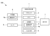
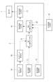
- FIG. 1 is a diagram illustrating an overall configuration of an image processing device and an endoscope system according to an embodiment.
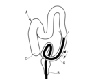
- FIG. 1 is a diagram illustrating the insertion and removal of an endoscope during colonoscopy.
- FIG. 2 is a diagram illustrating the relationship between position and time of images acquired during a colonoscopy.
- 4 is a flowchart of an example of an image processing method according to the first embodiment.
- 10 is a flowchart of another example of the image processing method according to the first embodiment.
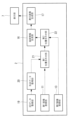
- FIG. 2 is a functional block diagram of an example of a processor of the image processing device according to the first embodiment.
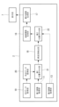
- FIG. 4 is a functional block diagram of another example of the processor of the image processing device according to the first embodiment.
- FIG. 1 is a diagram illustrating an overall configuration of an image processing device and an endoscope system according to an embodiment.
- FIG. 1 is a diagram illustrating the insertion and removal of an endoscope during colonoscopy.
- FIG. 2 is a diagram illustrating
- FIG. 4 is a functional block diagram of another example of the processor of the image processing device according to the first embodiment.
- 4 is a functional block diagram of another example of the processor of the image processing device according to the first embodiment.
- FIG. 13 is a diagram illustrating the relationship between a reference image and an image selected based on a similar image from the images in the time series being inserted.
- FIG. 11A and 11B are diagrams illustrating an example of subsequent information and a display image.
- 13A and 13B are diagrams showing other examples of subsequent information and display images.
- 13A and 13B are diagrams showing other examples of subsequent information and display images.
- 13A and 13B are diagrams illustrating the positional relationship between time-series images being inserted and 3D data.
- FIG. 10 is a flowchart of an example of an image processing method according to a second embodiment. 10 is a flowchart of another example of the image processing method according to the second embodiment.
- FIG. 11 is a functional block diagram of an example of a processor of the image processing device according to the second embodiment.
- FIG. 11 is a functional block diagram of another example of the processor of the image processing device according to the second embodiment.
- FIG. 11 is a functional block diagram of another example of the processor of the image processing device according to the second embodiment.
- FIG. 11 is a functional block diagram of another example of the processor of the image processing device according to the second embodiment.
- FIG. 11 is a functional block diagram of another example of the processor of the image processing device according to the second embodiment.
- FIG. 1 shows an endoscope system 100 to which an image processing device 1 according to this embodiment is applied.
- the endoscope system 100 includes an endoscope 6, the image processing device 1 that processes images acquired by the endoscope 6, and a display unit 7.
- the endoscope 6 is a flexible endoscope for the digestive system, and in this embodiment is a large intestine endoscope, as shown in Fig. 2.
- the endoscope 6 acquires an image of the inside of the large intestine A, which is an object of examination, by an image sensor 6a, and outputs the image to the image processing device 1.
- the display unit 7 is a known display such as a liquid crystal display.
- a typical colonoscopy examination consists of two steps: inserting the endoscope 6 into the large intestine A, and then removing the endoscope 6 from inside the large intestine A.
- the endoscope 6 is inserted from the anus B, passing through the sigmoid colon, descending colon, transverse colon, and ascending colon to the cecum C, and then removed from the cecum C to the anus B via the same route as when it was inserted.
- the doctor carefully observes the image while removing the endoscope 6 to diagnose the presence or absence of a lesion.
- the endoscope system 100 may further include a sensor 8 that detects the insertion distance of the endoscope 6 into the large intestine A.
- the insertion distance is the length of the endoscope 6 from the anus B to the tip of the endoscope 6.
- the sensor 8 is attached to the anus B, for example, and detects the amount of advancement and retreat of the endoscope 6.
- the sensor 8 may be of another known type.
- FIG. 3 shows the relationship between time and position in the large intestine A of images acquired by the endoscope 6.
- the position in the large intestine A of the time-series images during insertion changes in the direction of progression from the sigmoid colon to the cecum C
- the position in the large intestine A of the time-series images during removal changes in the direction of retreat from the cecum C to the sigmoid colon. Therefore, the time-series images during insertion and the time-series images during removal are arranged in the opposite direction with respect to time. Furthermore, the images during insertion and the images during removal are similar to each other.
- the image processing device 1 generates subsequent information D1, D2, D3 (described below) using the images during insertion, and displays the subsequent information D1, D2, D3 on the display unit 7 together with the images during removal, thereby assisting the doctor in making a diagnosis (see FIGS. 7A to 7C).
- the image processing device 1 includes a processor 2 such as a central processing unit, a memory 3 such as a RAM (Random Access Memory), a storage unit 4 , and an input/output unit 5 .
- the storage unit 4 is a computer-readable non-transitory recording medium such as a hard disk drive or a ROM (read-only memory).
- the storage unit 4 stores an image processing program 4 a for causing the processor 2 to execute an image processing method described below.
- the input/output unit 5 has a known input/output interface for images, and is connected to the endoscope 6 and the display unit 7 .
- the image processing method includes step S1 of recording a time series of images during insertion, step S2 of acquiring first deformation information of the images during insertion, step S3 of matching a reference image during removal with an image in the time series of images during insertion, step S4 of acquiring second deformation information of the reference image, step S5 of generating subsequent information D1, and step S6 of displaying the reference image together with the subsequent information D1.
- the processor 2 determines whether the endoscope 6 is currently being inserted or removed, and executes steps S1 to S2 while the endoscope 6 is being inserted, and executes steps S3 to S6 while the endoscope 6 is being removed. For example, the processor 2 determines that the endoscope 6 is currently being inserted based on the insertion distance detected by the sensor 8 increasing over time, and determines that the endoscope 6 is currently being removed based on the insertion distance decreasing over time.
- FIG. 5A shows functional units 11 to 17 of a processor 2 which executes an image processing method.
- the first image acquisition unit 11 acquires images during insertion input from the endoscope 6 through the input/output unit 5 to the image processing device 1, and records the images in sequence in the image recording unit 9.
- images in time series during insertion are recorded in the image recording unit 9.
- the image recording unit 9 is the memory 3, the storage unit 4, or any other arbitrary recording medium.
- the first deformation information generating unit 12 acquires first deformation information between the images in the time series being inserted.
- the first deformation information is information on the movement of the subject between the two images, for example, a motion vector between the two images. From the first deformation information, it is possible to estimate the relative positional relationship of the subject between the images in the time series.
- the first deformation information generation unit 12 receives an image from the first image acquisition unit 11 and encodes the image into an MPEG (Moving Picture Experts Group) file.
- the first deformation information is a motion vector between the current image and the previous image calculated in the encoding process.
- the first deformation information generation unit 12 records the encoded image in the image recording unit 9 in association with the first deformation information.
- FIG. 5B shows another example of the processor 2.
- the first deformation information generating unit 12 may obtain the first deformation information after the image being inserted is recorded in the image recording unit 9.
- step S2 in FIGS. 4A and 4B may be executed at any timing before step S4, and the unprocessed image may be recorded in the image recording unit 9. Steps S2 and S4 need only be completed before step S5 is executed.
- step S3 the second image acquisition unit 13 acquires an image during removal that is input from the endoscope 6 through the input/output unit 5 to the image processing device 1.
- the similar image extraction unit 14 evaluates the similarity between the reference image Itj and each image during insertion recorded in the image recording unit 9, and extracts one image Itj' with the highest similarity. As a result, the reference image Itj is associated with the most similar one image during insertion Itj'.
- the extracted image Itj' is referred to as a similar image.
- the similar image Itj' is an image whose position in the large intestine A is the same or approximately the same as that of the reference image Itj.
- the image being inserted may include deformation of the subject as well as rotation and scaling of the image relative to the reference image Itj. Therefore, in assessing the similarity, it is preferable to use a method of assessing similarity that includes non-rigid deformation of the subject, such as SIFT (Scale-Invariant Feature Transform) that uses features within the image.
- SIFT Scale-Invariant Feature Transform
- step S4 the second deformation information generation unit 15 receives the reference image Itj and the similar image Itj' as input and obtains second deformation information, which is deformation information between these two images.
- the second deformation information is, for example, a motion vector between the two images Itj and Itj'.
- step S5 the subsequent information generating unit 16 selects at least one image from the time-series images being inserted based on the similar image Itj'.
- the selected image is an image located close to the similar image Itj' and on the anus B side of the similar image Itj', and is typically the image Itj'-t1 acquired before the similar image Itj', as shown in FIG. 3. Therefore, as shown in FIG. 6, the selected image Itj'-t1 includes the field of view of the reference image Itj and its surrounding area.
- the subsequent information generating unit 16 generates subsequent information D1 from the selected image Itj'-t1 using the first deformation information and the second deformation information.
- the subsequent information D1 is information of the large intestine A in an image predicted to be acquired by the endoscope 6 being removed after the reference image Itj.
- the subsequent information D1 is an image of a region around the field of view of the reference image Itj that is arranged around the reference image Itj, and is shown as a hatched region in Fig. 7A. That is, the subsequent information D1 is an image of a region that will appear in an image acquired immediately after the reference image Itj, and includes information of the large intestine A that is not present in the reference image Itj.
- the subsequent information generation unit 16 extracts the area surrounding the field of view of the reference image Itj from the selected image Itj'-t1, and performs processing such as deformation, rotation, and enlargement/reduction on the extracted area based on the first deformation information and the second deformation information to generate subsequent information D1 that is aligned with the reference image Itj.
- step S6 the display image generating unit 17 generates a display image F in which the subsequent information D1 is added to the reference image Itj.
- the display image F includes the reference image Itj and an area E that is disposed outside the reference image Itj and surrounds the reference image Itj, and the area E is made up of the subsequent information D1.
- the display image generating unit 17 outputs the display image F to the display unit 7 to display it.
- the endoscope 6 is inserted and removed along the same path, and the doctor diagnoses the presence and condition of a lesion based on images taken during removal.
- subsequent information D1 is generated using an image acquired during insertion before removal, and the subsequent information D1 is displayed on the display unit 7 together with the current image Itj. Therefore, the doctor can predict in advance the area of the large intestine A that will appear in the image later, based on the subsequent information D1. In this way, by presenting the doctor with the additional subsequent information D1 in addition to the current image Itj, the doctor's diagnosis can be effectively supported, thereby reducing the oversight of a lesion.
- the processor 2 may further include a lesion detection unit 18 as a functional unit that detects a lesion in each image during insertion.
- the lesion detection unit 18 uses known Computer Aided Detection (CADe) technology to detect a lesion from each image during insertion, for example, based on texture and color (step S7).
- CADe Computer Aided Detection
- Information on the position of the lesion may be recorded in association with the image, for example, in the image recording unit 9.
- Step S7 may be executed at any timing before step S5.
- the subsequent information generator 16 may generate other subsequent information using information on the position of the detected lesion.
- Figures 7B and 7C show other examples of the subsequent information.
- the subsequent information D2 and D3 in Fig. 7B and Fig. 7C are displays arranged around the reference image Itj and indicate the position of the lesion.
- the subsequent information D2 in Fig. 7B is an arrow indicating the position of the lesion that will appear in the image after the reference image Itj.
- the subsequent information D3 in Fig. 7C is a marker displayed at the position of the lesion and is displayed superimposed on the subsequent information D1.
- Such subsequent information D2 and D3 can inform the user that a lesion will appear in the image later, together with its position.
- the subsequent information generator 16 performs processing such as deformation, rotation, and enlargement/reduction on the region of the lesion based on the first deformation information and the second deformation information to generate subsequent information D2, D3 aligned with the reference image Itj.
- the subsequent information is not limited to the above-mentioned subsequent information D1, D2, and D3, and may be in another form.
- the similar image extracting unit 14 may associate the reference image Itj with one of the images Itj' being inserted based on the insertion distance in addition to the similarity. 5D , during insertion and removal of the endoscope 6, the insertion distance detected by the sensor 8 is associated with a time stamp and recorded in the collateral information recording unit 10.
- the collateral information recording unit 10 is the memory 3, the storage unit 4, or any other arbitrary recording medium.
- Each of the image acquisition units 11 and 13 acquires an image with a time stamp.
- the similar image extraction unit 14 obtains the insertion distance of the reference image Itj from the auxiliary information recording unit 10 based on a timestamp, then selects one or more inserted images having an insertion distance that is the same as or close to the insertion distance of the reference image Itj based on the timestamp, and evaluates the similarity between the reference image Itj and each selected image. This reduces the time required to match the reference image Itj compared to evaluating the similarity between the reference image Itj and all images being inserted. In addition, once matching between the insertion time and the observation time is completed, the image to be evaluated for similarity may be selected using time stamp information.
- the image processing device 1 includes a processor 2, a memory 3, a storage unit 4, and an input/output unit 5, similarly to the first embodiment, and is applied to an endoscope system 100.
- the 3D data G is data of the three-dimensional shape of the entire colon A acquired in advance by a three-dimensional imaging device before colonoscopy, and is, for example, three-dimensional CT image data.
- the 3D data G is stored in the storage unit 4 or another predetermined recording medium before colonoscopy.
- the image processing program 4a causes the processor 2 to execute the image processing method shown in Fig. 9A.
- the image processing method of this embodiment includes step S11 of acquiring 3D data G, step S12 of recording time-series images during insertion, step S13 of associating a reference image during removal with one image in the time-series images during insertion, step S14 of generating subsequent information D1, and step S15 of displaying the reference image together with the subsequent information D1.
- the processor 2 executes steps S11 to S12 while the endoscope 6 is being inserted, and executes steps S13 to S15 while the endoscope 6 is being removed.
- FIG. 10A shows functional units 11, 13, 16, 17, 19 to 22 of a processor 2 which executes an image processing method.
- the 3D data acquisition unit 19 acquires the 3D data G from the storage unit 4 or a predetermined recording medium, and then the shape data acquisition unit 20 acquires the three-dimensional shape of the large intestine A from the 3D data G.
- the next step S12 includes step S121 of calculating the positional relationship between each of the time-series images being inserted and the 3D data G, and step S122 of generating 3D data with image information by attaching the time-series images being inserted to the 3D data G. Therefore, the time-series images being inserted may be recorded as a part of the 3D data with image information.
- the first image acquisition unit 11 acquires an image during insertion input from the endoscope 6 through the input/output unit 5 to the image processing device 1. Then, as shown in Fig. 8, the first alignment unit 21 aligns the image during insertion to a corresponding position in the 3D data G (step S121) and attaches the image to the corresponding position in the 3D data G (step S122). For example, the first alignment unit 21 may determine the corresponding position of each image by comparing each image with each position in the 3D data G.
- the first alignment unit 21 may reconstruct a three-dimensional model of the large intestine A from multiple images using a known technique such as SLAM (Simultaneous Localization and Mapping) and attach the reconstructed three-dimensional model to the 3D data G. The above process is repeated while the endoscope 6 is being inserted, thereby generating 3D data with image information onto which the texture of the large intestine A in the time-series images during insertion is attached.
- SLAM Simultaneous Localization and Mapping
- step S13 the second image acquisition unit 13 acquires the current image Itj during removal, which is input from the endoscope 6 through the input/output unit 5 to the image processing device 1.
- the second alignment unit 22 sets the current image Itj as a reference image, and matches the reference image Itj with one image being inserted based on the similarity between the reference image Itj and each image being inserted in the 3D data with image information.
- the image to be matched is the similar image Itj' that has the highest similarity to the reference image Itj, as in the first embodiment.
- step S14 the subsequent information generating unit 16 selects a portion of the 3D data with image information based on the similar image Itj', and generates subsequent information D1 from the selected portion.
- the selected portion is a portion in the vicinity of the similar image Itj' and closer to the anus B than the similar image Itj'.
- the subsequent information D1 is an image of the area around the field of view of the reference image Itj, which is arranged around the reference image Itj, as shown in FIG. 7A.
- step S15 the display image generating unit 17 generates a display image F and outputs it to the display unit 7, similarly to step S6 in the first embodiment.
- subsequent information D1 is generated using the image acquired during insertion before removal, and the subsequent information D1 is displayed on the display unit 7 together with the current image Itj. Therefore, the doctor can predict in advance the area of the large intestine A that will appear in the image later, based on the subsequent information D1. In this way, by presenting the doctor with additional subsequent information D1 in addition to the current image Itj, the doctor's diagnosis can be effectively supported, thereby reducing the oversight of lesions.
- the processor 2 may further include, as a functional unit, a lesion detection unit 18 that detects a lesion using CADe.
- the subsequent information generation unit 16 may generate subsequent information D2, D3 (see Figs. 7B and 7C) indicating the position of the lesion, similar to the first embodiment.
- Lesion detection unit 18 may detect a lesion in each image being inserted (see FIG. 10B), may detect a lesion in the 3D data with image information (see FIG. 10C), or may detect both a lesion in each image being inserted and a lesion in the 3D data with image information.
- step S16 of detecting a lesion may be performed at any timing before step S14 (see FIG. 9B).
- 10B the position of each lesion is recorded on an arbitrary recording medium in association with the image.
- the first alignment unit 21 generates 3D data with image information including the information of the lesion by adding information of the lesion to a corresponding position in the 3D data G based on the recorded position.
- the images and 3D data G of the endoscope 6 each have advantages and disadvantages in detecting a lesion.
- the image of the endoscope 6 can detect even a lesion with small irregularities, such as a small polyp less than 5 mm, based on color and texture, etc.
- 3D data G such as 3D CT images include the entire large intestine A. Therefore, according to the configuration of FIG. 10C, in addition to being able to detect lesions with small irregularities using an endoscope, lesions in areas that are difficult to capture using an endoscope can also be detected with high accuracy.
- lesion detection unit 18 may detect lesions in 3D data G.
- lesion detection unit 18 detects lesions from the three-dimensional shape of large intestine A acquired by shape data acquisition unit 20 using known techniques. The position of each detected lesion is recorded together with 3D data G in memory unit 4 or a specified recording medium.
- the subsequent information generator 16 may select a portion of the 3D data G based on the similar image Itj', and generate the subsequent information D1, D2, and D3 from the selected portion of the 3D data G.
- the selected portion is a portion in the vicinity of the similar image Itj' and closer to the anus B than the similar image Itj'.
- the first alignment unit 21 determines the position of each image being inserted in the 3D data G, but does not need to generate 3D data with image information.
- the second alignment unit 22 may determine a similar image Itj' based on the similarity between the reference image Itj and each image being inserted that is recorded in the image recording unit 9.
- the lesion in the 3D data G may be detected by a user such as a doctor instead of the processor 2.
- the user registers the position of the lesion in the 3D data G, for example, by attaching a marker to the position of the lesion in the 3D data G, and records the 3D data G with the registered position of the lesion in the storage unit 4 or a specified recording medium.
- the second alignment unit 22 may associate the reference image Itj with one of the images being inserted based on the insertion distance in addition to the similarity.
- the insertion distance detected by the sensor 8 is recorded in the auxiliary information recording unit 10 in association with a time stamp.
- Each of the image acquisition units 11 and 13 acquires an image with a time stamp.
- the second alignment unit 22 obtains the insertion distance of the reference image Itj from the auxiliary information recording unit 10 based on the timestamp, then selects one or more inserted images having an insertion distance that is the same as or close to the insertion distance of the reference image Itj based on the timestamp, and evaluates the similarity between the reference image Itj and each selected image. This reduces the time required to match the reference image Itj compared to evaluating the similarity between the reference image Itj and all images being inserted. In addition, once matching between the insertion time and the observation time is completed, the image to be evaluated for similarity may be selected using time stamp information.
- the present invention is not limited to this and can be modified as appropriate without departing from the gist of the present invention.
- the image processing device and image processing method of the present invention can be applied to endoscopic examination of other objects other than the large intestine, such as tubular objects, in which the insertion and removal path of the endoscope is the same.
- Image processing device 2 Processor 4a Image processing program 8 Sensor A Large intestine (test object) D1, D2, D3 Subsequent information F Display image Itj Reference image G Three-dimensional data
Landscapes
- Health & Medical Sciences (AREA)
- Life Sciences & Earth Sciences (AREA)
- Surgery (AREA)
- Nuclear Medicine, Radiotherapy & Molecular Imaging (AREA)
- Biomedical Technology (AREA)
- Optics & Photonics (AREA)
- Pathology (AREA)
- Radiology & Medical Imaging (AREA)
- Biophysics (AREA)
- Engineering & Computer Science (AREA)
- Physics & Mathematics (AREA)
- Heart & Thoracic Surgery (AREA)
- Medical Informatics (AREA)
- Molecular Biology (AREA)
- Animal Behavior & Ethology (AREA)
- General Health & Medical Sciences (AREA)
- Public Health (AREA)
- Veterinary Medicine (AREA)
- Endoscopes (AREA)
Priority Applications (3)
| Application Number | Priority Date | Filing Date | Title |
|---|---|---|---|
| JP2025520351A JPWO2024236795A1 (https=) | 2023-05-18 | 2023-05-18 | |
| CN202380097748.5A CN121038683A (zh) | 2023-05-18 | 2023-05-18 | 图像处理装置、图像处理方法以及图像处理程序 |
| PCT/JP2023/018554 WO2024236795A1 (ja) | 2023-05-18 | 2023-05-18 | 画像処理装置、画像処理方法および画像処理プログラム |
Applications Claiming Priority (1)
| Application Number | Priority Date | Filing Date | Title |
|---|---|---|---|
| PCT/JP2023/018554 WO2024236795A1 (ja) | 2023-05-18 | 2023-05-18 | 画像処理装置、画像処理方法および画像処理プログラム |
Publications (1)
| Publication Number | Publication Date |
|---|---|
| WO2024236795A1 true WO2024236795A1 (ja) | 2024-11-21 |
Family
ID=93519525
Family Applications (1)
| Application Number | Title | Priority Date | Filing Date |
|---|---|---|---|
| PCT/JP2023/018554 Ceased WO2024236795A1 (ja) | 2023-05-18 | 2023-05-18 | 画像処理装置、画像処理方法および画像処理プログラム |
Country Status (3)
| Country | Link |
|---|---|
| JP (1) | JPWO2024236795A1 (https=) |
| CN (1) | CN121038683A (https=) |
| WO (1) | WO2024236795A1 (https=) |
Citations (3)
| Publication number | Priority date | Publication date | Assignee | Title |
|---|---|---|---|---|
| JP2012170774A (ja) * | 2011-02-24 | 2012-09-10 | Fujifilm Corp | 内視鏡システム |
| WO2019220848A1 (ja) * | 2018-05-17 | 2019-11-21 | 富士フイルム株式会社 | 内視鏡装置、内視鏡操作方法、及びプログラム |
| WO2022014077A1 (ja) * | 2020-07-15 | 2022-01-20 | 富士フイルム株式会社 | 内視鏡システム及びその作動方法 |
-
2023
- 2023-05-18 JP JP2025520351A patent/JPWO2024236795A1/ja active Pending
- 2023-05-18 CN CN202380097748.5A patent/CN121038683A/zh active Pending
- 2023-05-18 WO PCT/JP2023/018554 patent/WO2024236795A1/ja not_active Ceased
Patent Citations (3)
| Publication number | Priority date | Publication date | Assignee | Title |
|---|---|---|---|---|
| JP2012170774A (ja) * | 2011-02-24 | 2012-09-10 | Fujifilm Corp | 内視鏡システム |
| WO2019220848A1 (ja) * | 2018-05-17 | 2019-11-21 | 富士フイルム株式会社 | 内視鏡装置、内視鏡操作方法、及びプログラム |
| WO2022014077A1 (ja) * | 2020-07-15 | 2022-01-20 | 富士フイルム株式会社 | 内視鏡システム及びその作動方法 |
Also Published As
| Publication number | Publication date |
|---|---|
| CN121038683A (zh) | 2025-11-28 |
| JPWO2024236795A1 (https=) | 2024-11-21 |
Similar Documents
| Publication | Publication Date | Title |
|---|---|---|
| CN113573654B (zh) | 用于检测并测定病灶尺寸的ai系统、方法和存储介质 | |
| JP6215236B2 (ja) | 生体内画像ストリーム中の運動性事象を表示するためのシステムおよび方法 | |
| JP6371729B2 (ja) | 内視鏡検査支援装置、内視鏡検査支援装置の作動方法および内視鏡支援プログラム | |
| CN101143099B (zh) | 医用图像诊断装置 | |
| US20110032347A1 (en) | Endoscopy system with motion sensors | |
| US20180263568A1 (en) | Systems and Methods for Clinical Image Classification | |
| JP2015509026A5 (https=) | ||
| JP4616872B2 (ja) | 画像表示装置および画像表示プログラム | |
| EP3977399A1 (en) | Systems and methods for video-based positioning and navigation in gastroenterological procedures | |
| US11423318B2 (en) | System and methods for aggregating features in video frames to improve accuracy of AI detection algorithms | |
| JP4891637B2 (ja) | 画像解析装置 | |
| US20180263527A1 (en) | Endoscope position specifying device, method, and program | |
| JP2007260144A (ja) | 医療用画像処理装置及び医療用画像処理方法 | |
| JP4616874B2 (ja) | 画像表示装置、画像表示方法、および画像表示プログラム | |
| WO2023126999A1 (ja) | 画像処理装置、画像処理方法、及び、記憶媒体 | |
| JP5554028B2 (ja) | 医用画像処理装置、医用画像処理プログラム、及びx線ct装置 | |
| US20250166297A1 (en) | Image processing apparatus, image processing method, and storage medium | |
| WO2024236795A1 (ja) | 画像処理装置、画像処理方法および画像処理プログラム | |
| JP4686279B2 (ja) | 医用診断装置及び診断支援装置 | |
| US11056149B2 (en) | Medical image storage and reproduction apparatus, method, and program | |
| US20180263712A1 (en) | Endoscope position specifying device, method, and program | |
| WO2024028924A1 (ja) | 内視鏡検査支援装置、内視鏡検査支援方法、及び、記録媒体 | |
| JP4981335B2 (ja) | 医療用画像処理装置及び医療用画像処理方法 | |
| JP7609278B2 (ja) | 画像処理装置、画像処理方法及びプログラム | |
| JP2008018016A (ja) | 医用画像処理装置及び医用画像処理方法 |
Legal Events
| Date | Code | Title | Description |
|---|---|---|---|
| 121 | Ep: the epo has been informed by wipo that ep was designated in this application |
Ref document number: 23937532 Country of ref document: EP Kind code of ref document: A1 |
|
| ENP | Entry into the national phase |
Ref document number: 2025520351 Country of ref document: JP Kind code of ref document: A |
|
| WWE | Wipo information: entry into national phase |
Ref document number: 2025520351 Country of ref document: JP |
|
| WWE | Wipo information: entry into national phase |
Ref document number: CN2023800977485 Country of ref document: CN |
|
| NENP | Non-entry into the national phase |
Ref country code: DE |