WO2024232244A1 - 情報処理装置、情報処理方法、およびプログラム - Google Patents
情報処理装置、情報処理方法、およびプログラム Download PDFInfo
- Publication number
- WO2024232244A1 WO2024232244A1 PCT/JP2024/015585 JP2024015585W WO2024232244A1 WO 2024232244 A1 WO2024232244 A1 WO 2024232244A1 JP 2024015585 W JP2024015585 W JP 2024015585W WO 2024232244 A1 WO2024232244 A1 WO 2024232244A1
- Authority
- WO
- WIPO (PCT)
- Prior art keywords
- information
- danger
- vehicle
- information processing
- processing device
- Prior art date
- Legal status (The legal status is an assumption and is not a legal conclusion. Google has not performed a legal analysis and makes no representation as to the accuracy of the status listed.)
- Ceased
Links
Images






Classifications
-
- G—PHYSICS
- G08—SIGNALLING
- G08G—TRAFFIC CONTROL SYSTEMS
- G08G1/00—Traffic control systems for road vehicles
- G08G1/16—Anti-collision systems
- G08G1/166—Anti-collision systems for active traffic, e.g. moving vehicles, pedestrians, bikes
-
- B—PERFORMING OPERATIONS; TRANSPORTING
- B60—VEHICLES IN GENERAL
- B60W—CONJOINT CONTROL OF VEHICLE SUB-UNITS OF DIFFERENT TYPE OR DIFFERENT FUNCTION; CONTROL SYSTEMS SPECIALLY ADAPTED FOR HYBRID VEHICLES; ROAD VEHICLE DRIVE CONTROL SYSTEMS FOR PURPOSES NOT RELATED TO THE CONTROL OF A PARTICULAR SUB-UNIT
- B60W30/00—Purposes of road vehicle drive control systems not related to the control of a particular sub-unit, e.g. of systems using conjoint control of vehicle sub-units
- B60W30/08—Active safety systems predicting or avoiding probable or impending collision or attempting to minimise its consequences
- B60W30/095—Predicting travel path or likelihood of collision
-
- B—PERFORMING OPERATIONS; TRANSPORTING
- B60—VEHICLES IN GENERAL
- B60W—CONJOINT CONTROL OF VEHICLE SUB-UNITS OF DIFFERENT TYPE OR DIFFERENT FUNCTION; CONTROL SYSTEMS SPECIALLY ADAPTED FOR HYBRID VEHICLES; ROAD VEHICLE DRIVE CONTROL SYSTEMS FOR PURPOSES NOT RELATED TO THE CONTROL OF A PARTICULAR SUB-UNIT
- B60W50/00—Details of control systems for road vehicle drive control not related to the control of a particular sub-unit, e.g. process diagnostic or vehicle driver interfaces
- B60W50/08—Interaction between the driver and the control system
- B60W50/14—Means for informing the driver, warning the driver or prompting a driver intervention
-
- G—PHYSICS
- G08—SIGNALLING
- G08G—TRAFFIC CONTROL SYSTEMS
- G08G1/00—Traffic control systems for road vehicles
- G08G1/005—Traffic control systems for road vehicles including pedestrian guidance indicator
-
- G—PHYSICS
- G08—SIGNALLING
- G08G—TRAFFIC CONTROL SYSTEMS
- G08G1/00—Traffic control systems for road vehicles
- G08G1/16—Anti-collision systems
- G08G1/161—Decentralised systems, e.g. inter-vehicle communication
- G08G1/163—Decentralised systems, e.g. inter-vehicle communication involving continuous checking
Definitions
- This technology relates to an information processing device, an information processing method, and a program, and in particular to an information processing device, an information processing method, and a program that can more appropriately present information for avoiding danger to users of moving objects such as vehicles.
- AR Augmented Reality
- Patent Document 1 there is technology that, when a sensor detects an obstacle, displays a template representing the object by superimposing it on an image of the vehicle's surroundings.
- the degree of danger based on the predicted results of vehicle movement and the position of an object is expressed by the size of a template, etc.
- the degree of danger is not calculated based on the predicted results of the object's movement, and the predicted results of the object's movement are not presented to the vehicle user, it is possible that sufficient information is not displayed to avoid danger.
- This technology was developed in light of these circumstances, and makes it possible to more effectively present information to users of moving objects such as vehicles to help them avoid danger.
- An information processing device includes a prediction unit that predicts motion information indicating future motion of objects around a moving body and accident information indicating the motion of the object in the event of an accident, a calculation unit that calculates the degree of danger of the object based on the motion information and the accident information, and a presentation control unit that presents the danger prediction information indicating the degree of danger of the object to a user of the moving body.
- an information processing device predicts movement information indicating the future movement of objects around a moving body and accident information indicating the movement of the objects if an accident occurs, calculates the degree of danger of the objects based on the movement information and the accident information, and presents danger prediction information indicating the degree of danger of the objects to a user of the moving body.
- a program causes a computer to execute a process of predicting motion information indicating the future motion of objects around a moving body and accident information indicating the motion of the objects if an accident occurs, calculating the degree of danger of the objects based on the motion information and the accident information, and presenting danger prediction information indicating the degree of danger of the objects to a user of the moving body.
- motion information indicating the future motion of objects around a moving body and accident information indicating the motion of the objects if an accident occurs are predicted, the degree of danger of the objects is calculated based on the motion information and the accident information, and danger prediction information indicating the degree of danger of the objects is presented to the user of the moving body.
- FIG. 1 is a block diagram showing an example of the configuration of a vehicle control system.
- FIG. 2 is a diagram showing an example of a sensing region.
- 1 is a block diagram showing a configuration example of a vehicle control system to which the present technology is applied.
- 4 is a flowchart illustrating a process performed by the vehicle control system.
- FIG. 11 is a diagram showing an example of risk prediction information.
- FIG. 11 is a diagram showing an example of risk prediction information indicating the degree of risk to a traveling vehicle.
- 11 is a diagram showing an example of risk prediction information indicating a risk level for a pedestrian crossing a crosswalk.
- FIG. FIG. 11 is a diagram showing an example of risk prediction information indicating the degree of risk for a bicycle.
- FIG. 11 is a diagram showing an example of risk prediction information indicating a risk level of a stopped vehicle.
- FIG. 13 is a diagram showing a display example of risk prediction information.
- FIG. 11 is a diagram showing a first modified example of risk prediction information.
- FIG. 11 is a diagram showing a second modified example of risk prediction information.
- 11 is a diagram showing an example of displaying danger prediction information to ensure visibility of the danger prediction information.
- FIG. 11A and 11B are diagrams illustrating an example of displaying danger prediction information for ensuring visibility of objects.
- FIG. 11 is a diagram illustrating an example of dangerous environment information.
- FIG. 11 is a diagram showing another example of dangerous environment information.
- FIG. 2 is a block diagram showing an example of the hardware configuration of a computer.
- FIG. 1 is a block diagram showing an example of the configuration of a vehicle control system 11, which is an example of a mobility device control system to which the present technology is applied.
- the vehicle control system 11 is provided in the vehicle 1 and performs processing related to the automated driving of the vehicle 1.
- This automated driving includes driving automation of levels 1 to 5, as well as remote driving and remote assistance of the vehicle 1 by a remote driver.
- the vehicle control system 11 includes a vehicle control ECU (Electronic Control Unit) 21, a communication unit 22, a map information storage unit 23, a location information acquisition unit 24, an external recognition sensor 25, an in-vehicle sensor 26, a vehicle sensor 27, a memory unit 28, a driving automation control unit 29, a DMS (Driver Monitoring System) 30, an HMI (Human Machine Interface) 31, and a vehicle control unit 32.
- vehicle control ECU Electronic Control Unit
- communication unit 22 includes a vehicle control ECU (Electronic Control Unit) 21, a communication unit 22, a map information storage unit 23, a location information acquisition unit 24, an external recognition sensor 25, an in-vehicle sensor 26, a vehicle sensor 27, a memory unit 28, a driving automation control unit 29, a DMS (Driver Monitoring System) 30, an HMI (Human Machine Interface) 31, and a vehicle control unit 32.
- the vehicle control ECU 21, communication unit 22, map information storage unit 23, position information acquisition unit 24, external recognition sensor 25, in-vehicle sensor 26, vehicle sensor 27, memory unit 28, driving automation control unit 29, DMS 30, HMI 31, and vehicle control unit 32 are connected to each other so as to be able to communicate with each other via a communication network 41.
- the communication network 41 is composed of an in-vehicle communication network or bus that complies with digital two-way communication standards such as CAN (Controller Area Network), LIN (Local Interconnect Network), LAN (Local Area Network), FlexRay (registered trademark), and Ethernet (registered trademark).
- the communication network 41 may be used differently depending on the type of data being transmitted.
- CAN may be applied to data related to vehicle control
- Ethernet may be applied to large-volume data.
- each part of the vehicle control system 11 may be directly connected without going through the communication network 41, using wireless communication intended for communication over relatively short distances, such as near field communication (NFC) or Bluetooth (registered trademark).
- NFC near field communication
- Bluetooth registered trademark
- the vehicle control ECU 21 is composed of various processors, such as a CPU (Central Processing Unit) and an MPU (Micro Processing Unit).
- the vehicle control ECU 21 controls all or part of the functions of the vehicle control system 11.
- the communication unit 22 communicates with various devices inside and outside the vehicle, other vehicles, servers, base stations, etc., and transmits and receives various types of data. At this time, the communication unit 22 can communicate using multiple communication methods.
- the communication unit 22 communicates with servers (hereinafter referred to as external servers) on an external network via base stations or access points using wireless communication methods such as 5G (fifth generation mobile communication system), LTE (Long Term Evolution), and DSRC (Dedicated Short Range Communications).
- the external network with which the communication unit 22 communicates is, for example, the Internet, a cloud network, or an operator-specific network.
- the communication method that the communication unit 22 uses with the external network is not particularly limited as long as it is a wireless communication method that allows digital two-way communication at a communication speed equal to or higher than a predetermined distance.
- the communication unit 22 can communicate with a terminal present in the vicinity of the vehicle using P2P (Peer To Peer) technology.
- the terminal present in the vicinity of the vehicle can be, for example, a terminal attached to a mobile object moving at a relatively slow speed, such as a pedestrian or a bicycle, a terminal installed at a fixed position in a store, or an MTC (Machine Type Communication) terminal.
- the communication unit 22 can also perform V2X communication.
- V2X communication refers to communication between the vehicle and others, such as vehicle-to-vehicle communication with other vehicles, vehicle-to-infrastructure communication with roadside devices, vehicle-to-home communication with a home, and vehicle-to-pedestrian communication with a terminal carried by a pedestrian, etc.
- the communication unit 22 can, for example, receive from the outside a program for updating software that controls the operation of the vehicle control system 11 (Over the Air).
- the communication unit 22 can further receive map information, traffic information, information about the surroundings of the vehicle 1, etc. from the outside.
- the communication unit 22 can also transmit information about the vehicle 1 and information about the surroundings of the vehicle 1 to the outside.
- Information about the vehicle 1 that the communication unit 22 transmits to the outside includes, for example, data indicating the state of the vehicle 1, the recognition results by the recognition unit 73, etc.
- the communication unit 22 performs communication corresponding to a vehicle emergency notification system such as e-Call.
- the communication unit 22 receives electromagnetic waves transmitted by a road traffic information and communication system (VICS (Vehicle Information and Communication System) (registered trademark)) such as a radio beacon, optical beacon, or FM multiplex broadcasting.
- VICS Vehicle Information and Communication System
- the communication unit 22 can communicate with each device in the vehicle using, for example, wireless communication.
- the communication unit 22 can perform wireless communication with each device in the vehicle using a communication method that allows digital two-way communication at a communication speed equal to or higher than a predetermined speed via wireless communication, such as wireless LAN, Bluetooth, NFC, or WUSB (Wireless USB).
- the communication unit 22 can also communicate with each device in the vehicle using wired communication.
- the communication unit 22 can communicate with each device in the vehicle using wired communication via a cable connected to a connection terminal (not shown).
- the communication unit 22 can communicate with each device in the vehicle using a communication method that allows digital two-way communication at a communication speed equal to or higher than a predetermined speed via wired communication, such as USB (Universal Serial Bus), HDMI (High-Definition Multimedia Interface) (registered trademark), or MHL (Mobile High-definition Link).
- a communication method that allows digital two-way communication at a communication speed equal to or higher than a predetermined speed via wired communication, such as USB (Universal Serial Bus), HDMI (High-Definition Multimedia Interface) (registered trademark), or MHL (Mobile High-definition Link).
- the in-vehicle device that communicates with the communication unit 22 refers to, for example, a device that is not connected to the communication network 41 inside the vehicle.
- Examples of in-vehicle devices include mobile devices and wearable devices carried by users inside the vehicle, such as the driver, and information devices that are brought into the vehicle and temporarily installed.
- the map information storage unit 23 stores one or both of a map acquired from an external source and a map created by the vehicle 1.
- the map information storage unit 23 stores a three-dimensional high-precision map, a global map that is less accurate than a high-precision map and covers a wide area, etc.
- High-precision maps include, for example, dynamic maps, point cloud maps, and vector maps.
- a dynamic map is, for example, a map consisting of four layers of dynamic information, semi-dynamic information, semi-static information, and static information, and is provided to the vehicle 1 from an external server or the like.
- a point cloud map is a map made up of a point cloud (point cloud data).
- a vector map is, for example, a map that is adapted for driving automation by associating traffic information such as the positions of lanes and traffic lights with a point cloud map.
- the point cloud map and vector map may be provided, for example, from an external server, or may be created by the vehicle 1 based on sensing results from the camera 51, radar 52, LiDAR 53, etc. as a map for matching with a local map described below, and stored in the map information storage unit 23.
- map data of, for example, an area of several hundred meters square regarding the planned route along which the vehicle 1 will travel is acquired from the external server, etc., in order to reduce communication capacity.
- the location information acquisition unit 24 receives GNSS signals from Global Navigation Satellite System (GNSS) satellites and acquires location information of the vehicle 1.
- GNSS Global Navigation Satellite System
- the acquired location information is supplied to the driving automation control unit 29.
- the location information acquisition unit 24 is not limited to a method using GNSS signals, and may acquire location information using a beacon, for example.
- the external recognition sensor 25 includes various sensors used to recognize the situation outside the vehicle 1, and supplies sensor data from each sensor to each part of the vehicle control system 11.
- the type and number of sensors included in the external recognition sensor 25 are arbitrary.
- the external recognition sensor 25 includes a camera 51, a radar 52, a LiDAR (Light Detection and Ranging, Laser Imaging Detection and Ranging) 53, and an ultrasonic sensor 54.
- the external recognition sensor 25 may be configured to include one or more types of sensors among the camera 51, the radar 52, the LiDAR 53, and the ultrasonic sensor 54.
- the number of cameras 51, radars 52, LiDAR 53, and ultrasonic sensors 54 is not particularly limited as long as it is a number that can be realistically installed on the vehicle 1.
- the types of sensors included in the external recognition sensor 25 are not limited to this example, and the external recognition sensor 25 may include other types of sensors. Examples of the sensing areas of each sensor included in the external recognition sensor 25 will be described later.
- the imaging method of camera 51 is not particularly limited.
- cameras of various imaging methods such as a ToF (Time Of Flight) camera, a stereo camera, a monocular camera, and an infrared camera, which are imaging methods capable of distance measurement, can be applied to camera 51 as necessary.
- ToF Time Of Flight
- stereo camera stereo camera
- monocular camera stereo camera
- infrared camera infrared camera
- the present invention is not limited to this, and camera 51 may simply be used for acquiring photographic images, without regard to distance measurement.
- the external recognition sensor 25 can be equipped with an environmental sensor for detecting the environment relative to the vehicle 1.
- the environmental sensor is a sensor for detecting the environment such as the weather, climate, brightness, etc., and can include various sensors such as a raindrop sensor, a fog sensor, a sunlight sensor, a snow sensor, an illuminance sensor, etc.
- the external recognition sensor 25 includes a microphone that is used to detect sounds around the vehicle 1 and the location of sound sources.
- the in-vehicle sensor 26 includes various sensors for detecting information inside the vehicle, and supplies sensor data from each sensor to each part of the vehicle control system 11. There are no particular limitations on the types and number of the various sensors included in the in-vehicle sensor 26, so long as they are of the types and number that can be realistically installed in the vehicle 1.
- the in-vehicle sensor 26 may be equipped with one or more types of sensors including a camera, radar, a seating sensor, a steering wheel sensor, a microphone, and a biometric sensor.
- the camera equipped in the in-vehicle sensor 26 may be a camera using various imaging methods capable of measuring distances, such as a ToF camera, a stereo camera, a monocular camera, or an infrared camera. Without being limited to this, the camera equipped in the in-vehicle sensor 26 may be a camera simply for acquiring captured images, regardless of distance measurement.
- the biometric sensor equipped in the in-vehicle sensor 26 is provided, for example, on a seat, steering wheel, etc., and detects various types of biometric information of the user.
- the vehicle sensor 27 includes various sensors for detecting the state of the vehicle 1, and supplies sensor data from each sensor to each part of the vehicle control system 11. There are no particular limitations on the types and number of the various sensors included in the vehicle sensor 27, so long as they are of the types and number that can be realistically installed on the vehicle 1.
- the vehicle sensor 27 includes a speed sensor, an acceleration sensor, an angular velocity sensor (gyro sensor), and an inertial measurement unit (IMU) that integrates these.
- the vehicle sensor 27 includes a steering angle sensor that detects the steering angle of the steering wheel, a yaw rate sensor, an accelerator sensor that detects the amount of accelerator pedal operation, and a brake sensor that detects the amount of brake pedal operation.
- the vehicle sensor 27 includes a rotation sensor that detects the number of rotations of the engine or motor, an air pressure sensor that detects the air pressure of the tires, a slip ratio sensor that detects the slip ratio of the tires, and a wheel speed sensor that detects the rotation speed of the wheels.
- the vehicle sensor 27 includes a battery sensor that detects the remaining charge and temperature of the battery, and an impact sensor that detects external impacts.
- the memory unit 28 includes at least one of a non-volatile storage medium and a volatile storage medium, and stores data and programs.
- the memory unit 28 is used, for example, as an EEPROM (Electrically Erasable Programmable Read Only Memory) and a RAM (Random Access Memory), and the storage medium may be a magnetic storage device such as a hard disc drive (HDD), a semiconductor storage device, an optical storage device, or a magneto-optical storage device.
- the memory unit 28 stores various programs and data used by each part of the vehicle control system 11.
- the memory unit 28 includes an EDR (Event Data Recorder) and a DSSAD (Data Storage System for Automated Driving), and stores information about the vehicle 1 before and after an event such as an accident, and information acquired by the in-vehicle sensor 26.
- EDR Event Data Recorder
- DSSAD Data Storage System for Automated Driving
- the driving automation control unit 29 controls the driving automation function of the vehicle 1.
- the driving automation control unit 29 includes an analysis unit 61, an action planning unit 62, and an operation control unit 63.
- the analysis unit 61 performs analysis processing of the vehicle 1 and the surrounding conditions.
- the analysis unit 61 includes a self-position estimation unit 71, a sensor fusion unit 72, and a recognition unit 73.
- the self-position estimation unit 71 estimates the self-position of the vehicle 1 based on the sensor data from the external recognition sensor 25 and the high-precision map stored in the map information storage unit 23. For example, the self-position estimation unit 71 generates a local map based on the sensor data from the external recognition sensor 25, and estimates the self-position of the vehicle 1 by matching the local map with the high-precision map.
- the position of the vehicle 1 is based on, for example, the center of the rear wheel pair axle.
- the local map is, for example, a three-dimensional high-precision map or an occupancy grid map created using technology such as SLAM (Simultaneous Localization and Mapping).
- the three-dimensional high-precision map is, for example, the point cloud map described above.
- the occupancy grid map is a map in which the three-dimensional or two-dimensional space around the vehicle 1 is divided into grids of a predetermined size, and the occupancy state of objects is shown on a grid-by-grid basis.
- the occupancy state of objects is indicated, for example, by the presence or absence of an object and the probability of its existence.
- the local map is also used, for example, in detection processing and recognition processing of the situation outside the vehicle 1 by the recognition unit 73.
- the self-position estimation unit 71 may estimate the self-position of the vehicle 1 based on the position information acquired by the position information acquisition unit 24 and the sensor data from the vehicle sensor 27.
- the sensor fusion unit 72 performs sensor fusion processing to obtain information by combining multiple different types of sensor data (e.g., image data supplied from the camera 51 and sensor data supplied from the radar 52). Methods for combining different types of sensor data include compounding, integration, fusion, and association.
- the recognition unit 73 executes a detection process to detect the situation outside the vehicle 1, and a recognition process to recognize the situation outside the vehicle 1.
- the recognition unit 73 performs detection and recognition processing of the situation outside the vehicle 1 based on information from the external recognition sensor 25, information from the self-position estimation unit 71, information from the sensor fusion unit 72, etc.
- the recognition unit 73 performs detection processing and recognition processing of objects around the vehicle 1.
- Object detection processing is, for example, processing to detect the presence or absence, size, shape, position, and movement (for example, the content of the action, direction of movement, and speed of movement) of an object.
- Object recognition processing is, for example, processing to recognize attributes such as the type of object, and to identify a specific object.
- detection processing and recognition processing are not necessarily clearly separated, and there may be overlap.
- the recognition unit 73 detects objects around the vehicle 1 by performing clustering to classify a point cloud based on sensor data from the radar 52, the LiDAR 53, or the like into clusters of points. This allows the presence or absence, size, shape, and position of objects around the vehicle 1 to be detected.
- the recognition unit 73 detects the movement of objects around the vehicle 1 by performing tracking to follow the movement of clusters of point clouds classified by clustering. This allows the speed and direction of travel (movement vector) of objects around the vehicle 1 to be detected.
- the recognition unit 73 detects or recognizes vehicles, people, bicycles, obstacles, structures, roads, traffic lights, traffic signs, road markings, etc. based on image data supplied from the camera 51.
- the recognition unit 73 may also recognize the types of objects around the vehicle 1 by performing recognition processing such as semantic segmentation.
- the recognition unit 73 can perform recognition processing of traffic rules around the vehicle 1 based on the map stored in the map information storage unit 23, the result of self-location estimation by the self-location estimation unit 71, and the result of recognition of objects around the vehicle 1 by the recognition unit 73. Through this processing, the recognition unit 73 can recognize the positions and states of traffic lights, the contents of traffic signs and road markings, the contents of traffic regulations, and lanes on which travel is possible, etc.
- the recognition unit 73 can perform recognition processing of the environment around the vehicle 1.
- the surrounding environment that the recognition unit 73 recognizes may include weather, temperature, humidity, brightness, and road surface conditions.
- the behavior planning unit 62 creates a behavior plan for the vehicle 1. For example, the behavior planning unit 62 creates the behavior plan by performing route planning and route following processing.
- Route planning includes global path planning and local path planning.
- Global path planning involves planning a rough route from the start to the goal.
- Local path planning is also called trajectory planning, and involves generating a trajectory that allows safe and smooth progress in the vicinity of vehicle 1 on the planned route, taking into account the motion characteristics of vehicle 1.
- Path following is a process of planning operations for safely and accurately traveling along a route planned by a route plan within a planned time.
- the action planning unit 62 can, for example, calculate the target speed and target angular velocity of the vehicle 1 based on the results of this path following process.
- the operation control unit 63 controls the operation of the vehicle 1 to realize the action plan created by the action planning unit 62.
- the operation control unit 63 controls the steering control unit 81, the brake control unit 82, and the drive control unit 83 included in the vehicle control unit 32 described below, and performs lateral vehicle motion control and longitudinal vehicle motion control so that the vehicle 1 proceeds along the trajectory calculated by the trajectory plan.
- the operation control unit 63 performs control aimed at driving automation, such as driver assistance functions such as collision avoidance or impact mitigation, following driving, maintaining vehicle speed, collision warning for the vehicle itself, and lane departure warning for the vehicle itself, and driving without the operation of the driver or a remote driver.
- the DMS 30 performs processes such as authenticating the driver and recognizing the driver's state based on the sensor data from the in-vehicle sensors 26 and the input data input to the HMI 31 (described later).
- Examples of the driver's state to be recognized include physical condition, alertness, concentration, fatigue, line of sight, level of intoxication, driving operation, posture, etc.
- the DMS 30 may also perform authentication processing for users other than the driver and recognition processing for the status of the users.
- the DMS 30 may also perform recognition processing for the status inside the vehicle based on sensor data from the in-vehicle sensor 26. Examples of the status inside the vehicle that may be recognized include temperature, humidity, brightness, odor, etc.
- HMI31 inputs various data and instructions, and displays various data to the user.
- the HMI 31 is equipped with an input device that allows a person to input data.
- the HMI 31 generates input signals based on data and instructions input via the input device, and supplies the signals to each part of the vehicle control system 11.
- the HMI 31 is equipped with input devices such as a touch panel, buttons, switches, and levers. Without being limited to these, the HMI 31 may further be equipped with an input device that allows information to be input by a method other than manual operation, such as voice or gestures.
- the HMI 31 may use, as an input device, an externally connected device such as a remote control device that uses infrared or radio waves, or a mobile device or wearable device that supports the operation of the vehicle control system 11.
- the HMI 31 generates visual information, auditory information, and tactile information for the user or the outside of the vehicle.
- the HMI 31 also performs output control to control the output, output content, output timing, output method, etc. of each piece of generated information.
- the HMI 31 generates and outputs, as visual information, information indicated by images or light, such as an operation screen, vehicle 1 status display, warning display, and monitor image showing the situation around the vehicle 1.
- the HMI 31 also generates and outputs, as auditory information, information indicated by sounds, such as voice guidance, warning sounds, and warning messages.
- the HMI 31 also generates and outputs, as tactile information, information that is imparted to the user's sense of touch by force, vibration, movement, etc.
- the output device to which the HMI 31 outputs visual information may be, for example, a display device that displays an image to present visual information, or a projector device that projects an image to present visual information.
- the display device may be, in addition to a display device having a normal display, a head-up display, a transparent display, or a display with an AR (Augmented Reality) function.
- the display device may be a device that displays visual information within the user's field of vision, such as a wearable device with an AR function. Examples of wearable devices include glasses-type displays, smartphones, and smart watches.
- the HMI 31 may also use display devices such as a navigation device, an instrument panel, a CMS (Camera Monitoring System), an electronic mirror, and lamps installed in the vehicle 1 as output devices to output visual information.
- the HMI 131 may also use, as output devices to output visual information, display devices attached thereto, such as an on-dash monitor, a tablet terminal, a drive recorder, and a display for a drive recorder.
- Output devices that output visual information are installed on the front of the dashboard in front of the driver's seat and passenger seat, on the console between the driver's seat and passenger seat, on the windshield, the steering wheel, on the back of the driver's seat and passenger seat, etc.
- the output device through which the HMI 31 outputs auditory information can be, for example, an audio speaker, headphones, or earphones.
- Haptic elements using haptic technology can be used as an output device for the HMI 31 to output haptic information.
- Haptic elements are provided on parts that the user touches, such as the steering wheel and the seat.
- haptic information may also be output by a smartphone, smartwatch, etc., carried by the user.
- the vehicle control unit 32 controls each part of the vehicle 1.
- the vehicle control unit 32 includes a steering control unit 81, a brake control unit 82, a drive control unit 83, a body control unit 84, a light control unit 85, and a horn control unit 86.
- the steering control unit 81 detects and controls the state of the steering system of the vehicle 1.
- the steering system includes, for example, a steering mechanism including a steering wheel, an electric power steering, etc.
- the steering control unit 81 includes, for example, a steering ECU that controls the steering system, an actuator that drives the steering system, etc.
- the brake control unit 82 detects and controls the state of the brake system of the vehicle 1.
- the brake system includes, for example, a brake mechanism including a brake pedal, an ABS (Antilock Brake System), a regenerative brake mechanism, etc.
- the brake control unit 82 includes, for example, a brake ECU that controls the brake system, and an actuator that drives the brake system.
- the drive control unit 83 detects and controls the state of the drive system of the vehicle 1.
- the drive system includes, for example, an accelerator pedal, a drive force generating device for generating drive force such as an internal combustion engine or a drive motor, and a drive force transmission mechanism for transmitting the drive force to the wheels.
- the drive control unit 83 includes, for example, a drive ECU for controlling the drive system, and an actuator for driving the drive system.
- the body system control unit 84 detects and controls the state of the body system of the vehicle 1.
- the body system includes, for example, a keyless entry system, a smart key system, a power window device, a power seat, an air conditioning system, an airbag, a seat belt, a shift lever, etc.
- the body system control unit 84 includes, for example, a body system ECU that controls the body system, an actuator that drives the body system, etc.
- the light control unit 85 detects and controls the state of various lights of the vehicle 1. Examples of lights to be controlled include headlights, backlights, fog lights, turn signals, brake lights, projection, and bumper displays.
- the light control unit 85 includes a light ECU that controls the lights, an actuator that drives the lights, and the like.
- the horn control unit 86 detects and controls the state of the car horn of the vehicle 1.
- the horn control unit 86 includes, for example, a horn ECU that controls the car horn, an actuator that drives the car horn, etc.
- FIG. 2 is a diagram showing an example of a sensing area by the camera 51, radar 52, LiDAR 53, ultrasonic sensor 54, etc. of the external recognition sensor 25 in FIG. 1. Note that FIG. 2 shows a schematic view of the vehicle 1 as seen from above, with the left end side being the front end of the vehicle 1 and the right end side being the rear end of the vehicle 1.
- Sensing area 101F and sensing area 101B show examples of sensing areas of ultrasonic sensors 54. Sensing area 101F covers the periphery of the front end of vehicle 1 with multiple ultrasonic sensors 54. Sensing area 101B covers the periphery of the rear end of vehicle 1 with multiple ultrasonic sensors 54.
- sensing results in sensing area 101F and sensing area 101B are used, for example, for parking assistance for vehicle 1.
- Sensing area 102F to sensing area 102B show examples of sensing areas of a short-range or medium-range radar 52. Sensing area 102F covers a position farther in front of the vehicle 1 than sensing area 101F. Sensing area 102B covers a position farther in the rear of the vehicle 1 than sensing area 101B. Sensing area 102L covers the rear periphery of the left side of the vehicle 1. Sensing area 102R covers the rear periphery of the right side of the vehicle 1.
- the sensing results in sensing area 102F are used, for example, to detect vehicles, pedestrians, etc., that are in front of vehicle 1.
- the sensing results in sensing area 102B are used, for example, for collision prevention functions behind vehicle 1.
- the sensing results in sensing area 102L and sensing area 102R are used, for example, to detect objects in blind spots to the sides of vehicle 1.
- Sensing area 103F to sensing area 103B show examples of sensing areas by camera 51. Sensing area 103F covers a position farther in front of vehicle 1 than sensing area 102F. Sensing area 103B covers a position farther in the rear of vehicle 1 than sensing area 102B. Sensing area 103L covers the periphery of the left side of vehicle 1. Sensing area 103R covers the periphery of the right side of vehicle 1.
- the sensing results in sensing area 103F can be used, for example, for recognizing traffic lights and traffic signs, lane departure prevention support systems, and automatic headlight control systems.
- the sensing results in sensing area 103B can be used, for example, for parking assistance and surround view systems.
- the sensing results in sensing area 103L and sensing area 103R can be used, for example, for surround view systems.
- Sensing area 104 shows an example of the sensing area of LiDAR 53. Sensing area 104 covers a position farther in front of vehicle 1 than sensing area 103F. On the other hand, sensing area 104 has a narrower range in the left-right direction than sensing area 103F.
- the sensing results in the sensing area 104 are used, for example, to detect objects such as surrounding vehicles.
- Sensing area 105 shows an example of the sensing area of long-range radar 52. Sensing area 105 covers a position farther in front of vehicle 1 than sensing area 104. On the other hand, sensing area 105 has a narrower range in the left-right direction than sensing area 104.
- the sensing results in the sensing area 105 are used, for example, for ACC (Adaptive Cruise Control), emergency braking, collision avoidance, etc.
- ACC Adaptive Cruise Control
- emergency braking braking
- collision avoidance etc.
- the sensing areas of the cameras 51, radar 52, LiDAR 53, and ultrasonic sensors 54 included in the external recognition sensor 25 may have various configurations other than those shown in FIG. 2. Specifically, the ultrasonic sensor 54 may also sense the sides of the vehicle 1, and the LiDAR 53 may sense the rear of the vehicle 1.
- the installation positions of the sensors are not limited to the examples described above. The number of sensors may be one or more.
- FIG. 3 is a block diagram showing an example configuration of a vehicle control system 11 to which this technology is applied.
- the vehicle control system 11 in FIG. 3 includes the above-mentioned configuration (external recognition sensor 25 and recognition unit 73), as well as an information processing unit 201 that calculates the degree of danger of objects around the vehicle 1 and generates danger prediction information indicating the degree of danger of the objects, and a display unit 202 that displays the danger prediction information.
- FIG. 3 shows the configuration of the portion of the vehicle control system 11 that is involved in displaying the danger prediction information.
- the recognition unit 73 acquires sensor data from the external recognition sensor 25, and performs recognition processing of objects around the vehicle 1 based on the sensor data using AI (Artificial Intelligence) trained using deep learning or other machine learning, neural networks, etc. Through the recognition processing, the recognition unit 73 recognizes, for example, the type, attributes, state, position, orientation, movement speed, and size of objects around the vehicle 1.
- AI Artificial Intelligence
- the type of object indicates whether the object is a pedestrian, a vehicle, a ball, a guardrail, a road sign, an obstacle, etc.
- the recognition unit 73 recognizes not only moving objects such as pedestrians, vehicles, and balls, but also stationary objects such as guardrails, signs, and obstacles.
- the object attributes indicate, for example, whether the pedestrian is a child or an elderly person. If the type of object is a vehicle, the object attributes indicate, for example, the model and color of the vehicle.
- the object state indicates, for example, that a pedestrian as an object is walking while looking at a smartphone, that the brake lights of a vehicle as an object are on, etc.
- the recognition unit 73 supplies the recognition results of the objects around the vehicle 1 to the information processing unit 201. Note that the recognition unit 73 may obtain information about the objects around the vehicle 1 from equipment other than the vehicle 1 via the communication unit 22, and perform recognition processing based on that information.
- the information processing unit 201 is part of the functions of the HMI 31.
- the information processing unit 201 is composed of a prediction unit 211, a risk calculation unit 212, and an image generation unit 213.
- the prediction unit 211 predicts the future movement of objects around the vehicle 1 and the movement of the objects in the event of an accident, based on the object recognition results by the recognition unit 73.
- the prediction unit 211 predicts the range that the object will reach in a few seconds as the object's future movement.
- the range that the object will reach in a few seconds is basically predicted based on the object's position, orientation, and movement speed.
- the range that an object will reach in a few seconds may be predicted based on a time series of the object's movement. For example, the range that an object will reach in a few seconds may be predicted based on the amount of movement of the object in a recent specified period of time. The range that an object will reach in a few seconds may also be predicted taking into account the state of the object, such as a pedestrian walking while looking at their smartphone, or a vehicle's brake lights being on.
- the prediction unit 211 predicts the possibility of an accident occurring and the movement of an object if an accident occurs (the range the object will reach in a few seconds) based on the attributes of the object, such as, for example, "children are likely to suddenly run out into the road” or "elderly people are likely to fall while crossing the road.”
- the prediction unit 211 can also predict the possibility of an accident occurring and the movement of an object if an accident occurs, taking into account the position of a stationary object, such as, for example, "because there is a guardrail, it is unlikely that a child will suddenly run out into the road.”
- the prediction unit 211 supplies the risk calculation unit 212 and the image generation unit 213 with movement information indicating the future movement of the object and accident information indicating the movement of the object if an accident occurs.
- the accident information includes information indicating the possibility of an accident occurring.
- the accident information may also include prediction difficulty, which is the degree of difficulty in predicting the future movement of the object.
- the risk calculation unit 212 calculates the risk of an object based on the object recognition result by the recognition unit 73, and the movement information and accident information supplied from the prediction unit 211. For example, the risk of a collision between the object and the vehicle 1 is estimated based on the range in which the object is predicted to arrive in a few seconds, and the moving direction and moving speed of the vehicle 1.
- the danger level calculation unit 212 supplies the danger level of the object to the image generation unit 213.
- the image generating unit 213 generates danger prediction information based on the movement information and accident information supplied from the prediction unit 211, and the danger level of the object supplied from the danger level calculation unit 212. Specifically, the image generating unit 213 controls the display mode of the danger prediction information based on at least one of the movement information, the accident information, and the danger level.
- the display mode of the danger prediction information includes color, shape (width, inclination of sides, direction), transparency, etc.
- the image generating unit 213 generates an image including the danger prediction information. For example, the image generating unit 213 superimposes the danger prediction information on a captured image showing the surroundings of the vehicle 1.
- the image generating unit 213 functions as a presentation control unit that controls the display unit 202 to present an image to the user of the vehicle 1.
- the display unit 202 is configured, for example, by a display installed inside the vehicle.
- the display unit 202 displays images according to the control of the image generation unit 213, and presents risk prediction information to the user of the vehicle 1.
- All or part of the functions of the recognition unit 73 and the information processing unit 201 may be provided in a device other than the vehicle 1, such as a cloud.
- the processing performed by the vehicle control system 11 having the above configuration will be described with reference to the flowchart in FIG. 4.
- the processing in FIG. 4 is started, for example, when an operation is performed to start the vehicle 1 and start driving, for example, when the ignition switch, power switch, start switch, etc. of the vehicle 1 is turned on.
- the processing in FIG. 4 is ended, for example, when an operation is performed to end driving of the vehicle 1, for example, when the ignition switch, power switch, start switch, etc. of the vehicle 1 is turned off.
- step S1 the external recognition sensor 25 senses the situation around the vehicle 1.
- step S2 the recognition unit 73 recognizes objects around the vehicle 1 based on the sensor data of the external recognition sensor.
- step S3 the information processing unit 201 determines whether or not an object has been recognized by the recognition unit 73.
- step S3 If it is determined in step S3 that an object has been recognized, the process proceeds to step S4.
- step S4 the prediction unit 211 predicts the future movement of the object recognized by the recognition unit 73 and the possibility of an accident occurring.
- step S5 the risk calculation unit 212 calculates the risk of the object recognized by the recognition unit 73 based on the recognition result by the recognition unit 73 and the prediction result by the prediction unit 211.
- step S5 After the danger level of the object is calculated in step S5, the process proceeds to step S6. If it is determined in step S3 that the object has not been recognized, steps S4 and S5 are skipped and the process proceeds to step S6.
- step S6 the image generation unit 213 generates an image to be presented to the user of the vehicle 1 by the display unit 202. If an object is recognized by the recognition unit 73, the image generation unit 213 generates an image to be presented by the display unit 202, for example, by superimposing danger prediction information on the captured image showing the surroundings of the vehicle 1. If an object is not recognized by the recognition unit 73, the image generation unit 213 uses, for example, the captured image showing the surroundings of the vehicle 1 as the image to be presented by the display unit 202.
- step S7 the display unit 202 presents an image to the user of the vehicle 1 according to the control of the image generation unit 213.
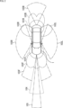
- Figure 5 shows an example of risk prediction information.
- the danger prediction information A1 has, for example, a rectangular shape with a long side connecting the pedestrian's head to his/her feet. Also, as shown in FIG. 5, when a pedestrian is moving or is predicted to move, the danger prediction information A1 has, for example, a trapezoid shape with rounded corners and a side connecting the pedestrian's head to his/her feet.
- the danger prediction information A1 has a bulging shape at the top of the edge on the side (left side) in the direction of movement in which the pedestrian is predicted to move, and the edge on that side of the direction of movement in the danger prediction information A1 bulges more the wider the range in which the pedestrian is predicted to reach in the next few seconds.
- the width (length of the upper side) of the danger prediction information A1 indicates the magnitude of the pedestrian's future movements.
- the direction of the bulge of the danger prediction information A1 indicates the predicted movement direction of the pedestrian.
- the outer angle (slope of the side facing the predicted movement direction of the pedestrian) of the vertex below (lower left) the predicted movement direction of the pedestrian in the danger prediction information A1 also indicates the magnitude of the pedestrian's future movements.
- the color of the danger prediction information A1 indicates the danger level to the pedestrian. If the danger level is low, the danger prediction information A1 is displayed in, for example, cyan, and if the danger level is medium, the danger prediction information A1 is displayed in, for example, yellow. If the danger level is high, the danger prediction information A1 is displayed in, for example, orange.
- the danger prediction information A1 is given a gradation, for example, such that the transparency increases the closer it gets to the pedestrian.
- the width of the danger prediction information A1 or the slope of the edge in the danger prediction information A1 that faces the predicted direction of pedestrian movement may indicate information other than the magnitude of the pedestrian's future movement.
- the width of the danger prediction information A1 may indicate, for example, the range of fluctuation in the pedestrian's future movement.
- the position of the edge in the danger prediction information A1 that faces the predicted direction of pedestrian movement indicates the upper limit of the range that the pedestrian may reach in a few seconds, and the position of the edge opposite the predicted direction of pedestrian movement indicates the lower limit of that range.
- the width of the danger prediction information A1 may indicate, for example, the danger level of the pedestrian.
- the slope of the edge of the danger prediction information A1 on the side of the predicted direction of movement of the pedestrian may indicate the predicted movement speed of the pedestrian.
- Figure 6 shows an example of risk prediction information that indicates the risk level of a moving vehicle.
- the vehicle control system 11 calculates a high level of danger for vehicle C1 and displays danger prediction information A11 indicating the danger level of vehicle C1 in orange, superimposed on a portion of vehicle C1, as shown in FIG. 6. Since vehicle C1 is predicted to travel at high speed, the vehicle control system 11, for example, increases the width of the danger prediction information A11 and decreases the slope of the left side of the danger prediction information A11.
- Figure 7 shows an example of risk prediction information that indicates the risk level for pedestrians crossing a crosswalk.
- the vehicle control system 11 calculates a medium level of danger for pedestrian P1 and displays danger prediction information A12 indicating the danger level for pedestrian P1 in yellow, superimposed on a portion of pedestrian P1, as shown in FIG. 7. Because pedestrian P1 is predicted to move at a low speed, the vehicle control system 11, for example, reduces the width of the danger prediction information A12 and increases the slope of the left side of the danger prediction information A12.
- point Po1 may be displayed superimposed on the head of pedestrian P1.
- point Po1 it becomes easier for users of vehicle 1 to know that there is a pedestrian. If it is possible to recognize the presence of pedestrian P1 around vehicle 1, but it is not possible to recognize the direction of pedestrian P1 or to predict the future movements of pedestrian P1, it is possible to display only point Po1 without displaying danger prediction information A12.
- Figure 8 shows an example of risk prediction information that indicates the risk level of bicycles.
- vehicle control system 11 calculates a high level of danger for bicycle B1 and displays danger prediction information A13 indicating the danger level for the bicycle in orange, superimposed on a portion of the bicycle, as shown in Figure 8.
- vehicle control system 11 increases the width of danger prediction information A13 and decreases the slope of the right side of danger prediction information A13. Because bicycle B1 is predicted to move toward the rear right (to the front right of vehicle 1), danger prediction information A13 is drawn according to perspective so that the user of vehicle 1 can easily see that bicycle B1 is moving toward the rear right.
- point Po2 may be displayed superimposed on the head of the person riding bicycle B1.
- FIG. 9 shows an example of risk prediction information that indicates the risk of a stopped vehicle.
- the vehicle control system 11 calculates a low risk level for vehicle C2 and displays risk prediction information A14 indicating the risk level for vehicle C2 in cyan, as shown in FIG. 9.
- the danger level of a stopped vehicle or a stationary obstacle is indicated, for example, by columnar danger prediction information placed at the corners of a bounding box that surrounds the bottom of the vehicle or obstacle.
- the above-mentioned danger prediction information may be displayed on a display mounted inside vehicle 1, superimposed on a captured image showing the surroundings of vehicle 1, or may be displayed on a head-up display so as to be superimposed on real objects.
- the display format of the risk prediction information is not limited to the display format described with reference to Figures 5 to 9.
- Figure 10 shows an example of how risk prediction information is displayed.
- danger prediction information A21 to A24 are displayed superimposed on the captured image showing the surroundings of vehicle 1.
- Danger prediction information A21 indicates the danger level of a pedestrian moving backwards as seen by the user of vehicle 1
- danger prediction information A22 indicates the danger level of a pedestrian crossing the road.
- Danger prediction information A23 indicates the danger level of a pedestrian about to cross the road
- danger prediction information A24 indicates the danger level of a vehicle stopped on the road.
- movement information indicating the future movement of objects around the vehicle 1 and accident information indicating the movement of the objects if an accident occurs are predicted, the degree of danger of the objects is calculated based on the movement information and the accident information, and danger prediction information indicating the degree of danger of the objects is presented to the user of the vehicle 1.
- the vehicle control system 11 does not simply warn that a dangerous object has been recognized, but visually indicates which object is moving in which direction and how dangerous each object is. Therefore, the vehicle control system 11 can ideally present information to the user of the vehicle 1 for avoiding danger. This allows the user of the vehicle 1 to intuitively know potential danger, and the vehicle control system 11 can achieve safe driving of the vehicle 1.
- the range where an object is predicted to reach in a few seconds is indicated by two-dimensional danger prediction information.
- the two-dimensional danger prediction information may not be able to simultaneously indicate the range where the object is predicted to move in normal times and the range where the object is predicted to move when an accident occurs. Therefore, the range where the object is predicted to reach in a few seconds may be indicated by three-dimensional danger prediction information.
- FIG. 11 shows a first modified example of risk prediction information.
- the shape of the danger prediction information A51 is an approximate sphere that envelops the entire pedestrian as an object, and a gradation is applied to the danger prediction information A51 such that the transparency gradually increases from the front to the back of the pedestrian.
- the possibility that the pedestrian will suddenly move to the left can be expressed, for example, by expanding the part of the spherical surface of the danger prediction information A51 that is to the left as seen from the pedestrian's perspective, as shown in FIG. 11B.
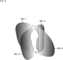
- FIG. 12 shows a second modified example of the danger prediction information.
- Hazard prediction information of multiple planes corresponding to multiple directions of movement in which an object is predicted to move may be displayed.
- four pieces of danger prediction information A61-1 to A61-4 are superimposed on one pedestrian.
- Danger prediction information A61-1 indicates the range in the front direction that the pedestrian is predicted to reach in a few seconds
- danger prediction information A61-2 indicates the range in the left direction that the pedestrian is predicted to reach in a few seconds
- Danger prediction information A61-3 indicates the range in the right direction that the pedestrian is predicted to reach in a few seconds
- danger prediction information A61-4 indicates the range in the rear direction that the pedestrian is predicted to reach in a few seconds.
- the danger prediction information A61-1 to A61-4 may be displayed in one color according to the danger level of the pedestrian. Also, each of the danger prediction information A61-1 to A61-4 may be displayed in a color according to the danger level when the pedestrian moves in each of the directions, forward/backward/left/right.
- FIG. 13 is a diagram showing an example of displaying danger prediction information to ensure the visibility of the danger prediction information.
- image processing is performed to reduce the brightness or saturation of the entire captured image showing the surroundings of the vehicle 1, and the danger prediction information A21 to A24 may be superimposed on this image.
- danger prediction information is superimposed on the captured image showing the surroundings of the vehicle 1 as is, the danger prediction information may become difficult to see.
- By lowering the brightness or saturation of the captured image it is possible to ensure the visibility of the danger prediction information.
- image processing that reduces brightness or saturation may be applied to the entire captured image, or it may be applied only to the area surrounding the portion of the captured image where the danger prediction information is superimposed.
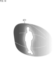
- FIG. 14 shows an example of how danger prediction information is displayed to ensure visibility of objects.
- danger prediction information A71 that envelops the entire object is displayed
- the transparency of the area along the contour of the object in the danger prediction information A71 may be increased, as shown in FIG. 14.
- danger prediction information is superimposed on an object, the object itself may become difficult to see.
- By increasing the transparency of the area surrounding the object in the danger prediction information it is possible to ensure the visibility of the object on which the danger prediction information is superimposed.
- Example of Considering Driving Environment The future movement of an object and the possibility of an accident occurring may be predicted based on not only the type, attribute, state, position, orientation, moving speed, and size of the object but also the driving environment of the vehicle 1. In addition, the degree of danger of the object may be calculated based on the driving environment of the vehicle 1.
- the driving environment of vehicle 1 includes the location, time of day, weather, and so on. For example, in a school zone, there is a high possibility that children will run out onto the road. In rainy or snowy weather, the braking distance of vehicle 1 will be longer when the brakes are applied. Furthermore, in rainy or snowy weather, there is a high possibility that pedestrians will fall. In this way, the driving environment of vehicle 1 is taken into consideration when predicting the future movement of objects, the possibility of accidents occurring, and calculating the degree of danger of objects.
- the danger prediction information may be displayed with more emphasis than when the vehicle 1 is traveling in a normal driving environment. Also, dangerous environment information indicating the danger level of the driving environment may be displayed.
- FIG. 15 shows an example of hazardous environment information.
- dangerous environment information A81 which indicates in color that the road surface is highly dangerous, is displayed superimposed on a portion of the road surface.
- the dangerous environment information A81 is displayed in orange, for example.
- an icon and text indicating that it is raining are displayed, for example, in the bottom right corner of the screen of the display unit 202, alerting the user of the vehicle 1 that the road surface is wet and therefore there is a high possibility of an accident occurring.
- FIG. 16 shows another example of hazardous environment information.
- dangerous environment information A91, A92 is displayed superimposed on the blind spots, as shown in FIG. 16.
- dangerous environment information A91, A92 for example, if a pedestrian rushes out from a blind spot, the width of the area that the pedestrian is predicted to reach in a few seconds is displayed, and the degree of danger for the pedestrian is displayed in color.
- the present technology can be applied to various products.
- the present technology may be realized as a device mounted on any type of moving object, such as an automobile, an electric vehicle, a hybrid electric vehicle, a motorcycle, a bicycle, a personal mobility device, an airplane, a drone, a ship, or a robot.
- the above-described series of processes can be executed by hardware or software.
- the program constituting the software is installed from a program recording medium into a computer incorporated in dedicated hardware, or into a general-purpose personal computer, etc.
- FIG. 17 is a block diagram showing an example of the hardware configuration of a computer that executes the above-mentioned series of processes by a program.
- the information processing unit 201 is, for example, a PC having a configuration similar to that shown in FIG. 17.
- CPU 501 CPU 501
- ROM (Read Only Memory) 502 RAM 503 are interconnected by bus 504.
- an input/output interface 505 Connected to the input/output interface 505 are an input unit 506 consisting of a keyboard, mouse, etc., and an output unit 507 consisting of a display, speakers, etc. Also connected to the input/output interface 505 are a storage unit 508 consisting of a hard disk or non-volatile memory, a communication unit 509 consisting of a network interface, etc., and a drive 510 that drives removable media 511.
- the CPU 501 for example, loads a program stored in the storage unit 508 into the RAM 503 via the input/output interface 505 and the bus 504 and executes the program, thereby performing the above-mentioned series of processes.
- the programs executed by the CPU 501 are provided, for example, by being recorded on removable media 511, or via a wired or wireless transmission medium such as a local area network, the Internet, or digital broadcasting, and are installed in the storage unit 508.
- the program executed by the computer may be a program in which processing is performed chronologically in the order described in this specification, or a program in which processing is performed in parallel or at the required timing, such as when called.
- a system refers to a collection of multiple components (devices, modules (parts), etc.), regardless of whether all the components are in the same housing. Therefore, multiple devices housed in separate housings and connected via a network, and a single device in which multiple modules are housed in a single housing, are both systems.
- this technology can be configured as cloud computing, in which a single function is shared and processed collaboratively by multiple devices over a network.
- each step described in the above flowchart can be executed by a single device, or can be shared and executed by multiple devices.
- a single step includes multiple processes
- the processes included in that single step can be executed by a single device, or can be shared and executed by multiple devices.
- Example of combination of configurations The present technology can also have the following configurations.
- the information processing device controls a display mode of the danger prediction information based on at least one of a danger level of the object, the movement information, and the accident information.
- the presentation control unit controls a color of the danger prediction information based on a degree of danger of the object.
- the presentation control unit controls a shape of the risk prediction information based on a direction in which the object is predicted to move.
- the information processing device (11) The information processing device according to (10), wherein the presentation control unit displays a plurality of pieces of risk prediction information corresponding to a plurality of moving directions in which one of the objects is predicted to move, superimposed on the one of the objects or around the one of the objects. (12) The calculation unit calculates a degree of danger of the object for each of the moving directions of the object, The information processing device according to (11), wherein the presentation control unit controls a color of each of the plurality of pieces of danger prediction information based on the degree of danger of the object calculated for each of the moving directions. (13) The information processing device according to any one of (8) to (12), wherein the presentation control unit controls a shape of the risk prediction information based on a range in which the object is predicted to move.
- the information processing device controls an angle of a side included in the risk prediction information based on a predicted moving speed of the object.
- the presentation control unit controls a shape of the danger prediction information based on a degree of danger of the object.
- the presentation control unit presents dangerous environment information indicating a degree of danger of an environment around the moving object to the user.
- the prediction unit predicts the movement information and the accident information based on sensor data of a sensor provided in the moving body and sensing a surrounding of the moving body.
Landscapes
- Engineering & Computer Science (AREA)
- Automation & Control Theory (AREA)
- Physics & Mathematics (AREA)
- General Physics & Mathematics (AREA)
- Transportation (AREA)
- Mechanical Engineering (AREA)
- Human Computer Interaction (AREA)
- Traffic Control Systems (AREA)
Priority Applications (3)
| Application Number | Priority Date | Filing Date | Title |
|---|---|---|---|
| JP2025519365A JPWO2024232244A1 (https=) | 2023-05-10 | 2024-04-19 | |
| DE112024001995.1T DE112024001995T5 (de) | 2023-05-10 | 2024-04-19 | Informationsverarbeitungsvorrichtung, informationsverarbeitungsverfahren und programm |
| CN202480029893.4A CN121127898A (zh) | 2023-05-10 | 2024-04-19 | 信息处理设备、信息处理方法和程序 |
Applications Claiming Priority (2)
| Application Number | Priority Date | Filing Date | Title |
|---|---|---|---|
| JP2023-077719 | 2023-05-10 | ||
| JP2023077719 | 2023-05-10 |
Publications (1)
| Publication Number | Publication Date |
|---|---|
| WO2024232244A1 true WO2024232244A1 (ja) | 2024-11-14 |
Family
ID=93429957
Family Applications (1)
| Application Number | Title | Priority Date | Filing Date |
|---|---|---|---|
| PCT/JP2024/015585 Ceased WO2024232244A1 (ja) | 2023-05-10 | 2024-04-19 | 情報処理装置、情報処理方法、およびプログラム |
Country Status (4)
| Country | Link |
|---|---|
| JP (1) | JPWO2024232244A1 (https=) |
| CN (1) | CN121127898A (https=) |
| DE (1) | DE112024001995T5 (https=) |
| WO (1) | WO2024232244A1 (https=) |
Citations (10)
| Publication number | Priority date | Publication date | Assignee | Title |
|---|---|---|---|---|
| JP2007051973A (ja) * | 2005-08-19 | 2007-03-01 | Denso Corp | 危険箇所情報表示装置 |
| JP2008123217A (ja) * | 2006-11-10 | 2008-05-29 | Toyota Motor Corp | 障害物進路予測方法、装置、およびプログラム |
| JP2011248445A (ja) * | 2010-05-24 | 2011-12-08 | Toyota Central R&D Labs Inc | 可動物予測装置及びプログラム |
| JP2017021546A (ja) * | 2015-07-10 | 2017-01-26 | 田山 修一 | 車輌用画像表示システム及び方法 |
| WO2017056382A1 (ja) * | 2015-09-29 | 2017-04-06 | ソニー株式会社 | 情報処理装置、情報処理方法、及びプログラム |
| WO2017060978A1 (ja) * | 2015-10-06 | 2017-04-13 | 株式会社日立製作所 | 自動運転制御装置および自動運転制御方法 |
| JP2019109691A (ja) * | 2017-12-18 | 2019-07-04 | 日立オートモティブシステムズ株式会社 | 移動体挙動予測装置および移動体挙動予測方法 |
| JP2019124539A (ja) * | 2018-01-15 | 2019-07-25 | キヤノン株式会社 | 情報処理装置及びその制御方法及びプログラム |
| JP2021117704A (ja) * | 2020-01-24 | 2021-08-10 | 株式会社リコー | 表示装置、及び表示方法 |
| JP2023184097A (ja) * | 2022-06-17 | 2023-12-28 | トヨタ自動車株式会社 | 運転支援システム、運転支援方法、及び運転支援プログラム |
Family Cites Families (1)
| Publication number | Priority date | Publication date | Assignee | Title |
|---|---|---|---|---|
| US12522142B2 (en) | 2019-10-23 | 2026-01-13 | Sony Group Corporation | Display system, display device, display method, and mobile apparatus |
-
2024
- 2024-04-19 WO PCT/JP2024/015585 patent/WO2024232244A1/ja not_active Ceased
- 2024-04-19 JP JP2025519365A patent/JPWO2024232244A1/ja active Pending
- 2024-04-19 CN CN202480029893.4A patent/CN121127898A/zh active Pending
- 2024-04-19 DE DE112024001995.1T patent/DE112024001995T5/de active Pending
Patent Citations (10)
| Publication number | Priority date | Publication date | Assignee | Title |
|---|---|---|---|---|
| JP2007051973A (ja) * | 2005-08-19 | 2007-03-01 | Denso Corp | 危険箇所情報表示装置 |
| JP2008123217A (ja) * | 2006-11-10 | 2008-05-29 | Toyota Motor Corp | 障害物進路予測方法、装置、およびプログラム |
| JP2011248445A (ja) * | 2010-05-24 | 2011-12-08 | Toyota Central R&D Labs Inc | 可動物予測装置及びプログラム |
| JP2017021546A (ja) * | 2015-07-10 | 2017-01-26 | 田山 修一 | 車輌用画像表示システム及び方法 |
| WO2017056382A1 (ja) * | 2015-09-29 | 2017-04-06 | ソニー株式会社 | 情報処理装置、情報処理方法、及びプログラム |
| WO2017060978A1 (ja) * | 2015-10-06 | 2017-04-13 | 株式会社日立製作所 | 自動運転制御装置および自動運転制御方法 |
| JP2019109691A (ja) * | 2017-12-18 | 2019-07-04 | 日立オートモティブシステムズ株式会社 | 移動体挙動予測装置および移動体挙動予測方法 |
| JP2019124539A (ja) * | 2018-01-15 | 2019-07-25 | キヤノン株式会社 | 情報処理装置及びその制御方法及びプログラム |
| JP2021117704A (ja) * | 2020-01-24 | 2021-08-10 | 株式会社リコー | 表示装置、及び表示方法 |
| JP2023184097A (ja) * | 2022-06-17 | 2023-12-28 | トヨタ自動車株式会社 | 運転支援システム、運転支援方法、及び運転支援プログラム |
Also Published As
| Publication number | Publication date |
|---|---|
| JPWO2024232244A1 (https=) | 2024-11-14 |
| CN121127898A (zh) | 2025-12-12 |
| DE112024001995T5 (de) | 2026-03-05 |
Similar Documents
| Publication | Publication Date | Title |
|---|---|---|
| JP7663839B2 (ja) | 信号処理装置、信号処理方法、プログラム、及び、移動装置 | |
| JP7615141B2 (ja) | 情報処理装置、情報処理方法、およびプログラム | |
| WO2022259621A1 (ja) | 情報処理装置、情報処理方法、コンピュータプログラム | |
| JP7786398B2 (ja) | 情報処理装置、情報処理方法、プログラム、移動装置、及び、情報処理システム | |
| JP7626632B2 (ja) | 情報処理装置、および情報処理方法、並びにプログラム | |
| US20210300401A1 (en) | Information processing device, moving body, information processing method, and program | |
| WO2020116195A1 (ja) | 情報処理装置、情報処理方法、プログラム、移動体制御装置、及び、移動体 | |
| US12511762B2 (en) | Learning model generation method, information processing device, and information processing system | |
| JP7852098B2 (ja) | 情報処理装置、および情報処理システム、並びにプログラム | |
| CN113841100A (zh) | 自主行驶控制设备、自主行驶控制系统和自主行驶控制方法 | |
| US12387361B2 (en) | Information processing to appropriately interpret a recognition result of an object recognition model | |
| WO2022201892A1 (en) | Information processing apparatus, information processing method, and program | |
| US20250172950A1 (en) | Information processing apparatus, information processing method, information processing program, and mobile apparatus | |
| US20240386724A1 (en) | Recognition processing device, recognition processing method, and recognition processing system | |
| US20250155258A1 (en) | Information processing device, information processing method, and moving body | |
| WO2024009829A1 (ja) | 情報処理装置、情報処理方法および車両制御システム | |
| WO2024232244A1 (ja) | 情報処理装置、情報処理方法、およびプログラム | |
| US20250225866A1 (en) | Signal processing apparatus, signal processing method, and recording medium | |
| US20260045152A1 (en) | Information processing apparatus, information processing method, and program | |
| US12620311B2 (en) | Information processing apparatus, information processing method, and program | |
| US20260051180A1 (en) | Information processing device and information processing method | |
| US20260004594A1 (en) | Information processing device, information processing method, and information processing system | |
| WO2024232245A1 (ja) | 情報処理装置、情報処理方法、およびプログラム | |
| WO2024252912A1 (ja) | 情報処理装置、情報処理方法、および情報処理システム | |
| JP2024178673A (ja) | 情報処理装置、情報処理方法及び情報処理プログラム |
Legal Events
| Date | Code | Title | Description |
|---|---|---|---|
| 121 | Ep: the epo has been informed by wipo that ep was designated in this application |
Ref document number: 24803358 Country of ref document: EP Kind code of ref document: A1 |
|
| ENP | Entry into the national phase |
Ref document number: 2025519365 Country of ref document: JP Kind code of ref document: A |
|
| WWE | Wipo information: entry into national phase |
Ref document number: 2025519365 Country of ref document: JP |
|
| WWE | Wipo information: entry into national phase |
Ref document number: 112024001995 Country of ref document: DE |
|
| WWP | Wipo information: published in national office |
Ref document number: 112024001995 Country of ref document: DE |