WO2024232194A1 - 内燃機関 - Google Patents
内燃機関 Download PDFInfo
- Publication number
- WO2024232194A1 WO2024232194A1 PCT/JP2024/013634 JP2024013634W WO2024232194A1 WO 2024232194 A1 WO2024232194 A1 WO 2024232194A1 JP 2024013634 W JP2024013634 W JP 2024013634W WO 2024232194 A1 WO2024232194 A1 WO 2024232194A1
- Authority
- WO
- WIPO (PCT)
- Prior art keywords
- bottom wall
- step portion
- wall
- cavity
- cylinder head
- Prior art date
- Legal status (The legal status is an assumption and is not a legal conclusion. Google has not performed a legal analysis and makes no representation as to the accuracy of the status listed.)
- Ceased
Links
Images


Classifications
-
- F—MECHANICAL ENGINEERING; LIGHTING; HEATING; WEAPONS; BLASTING
- F02—COMBUSTION ENGINES; HOT-GAS OR COMBUSTION-PRODUCT ENGINE PLANTS
- F02F—CYLINDERS, PISTONS OR CASINGS, FOR COMBUSTION ENGINES; ARRANGEMENTS OF SEALINGS IN COMBUSTION ENGINES
- F02F1/00—Cylinders; Cylinder heads
- F02F1/004—Cylinder liners
-
- F—MECHANICAL ENGINEERING; LIGHTING; HEATING; WEAPONS; BLASTING
- F02—COMBUSTION ENGINES; HOT-GAS OR COMBUSTION-PRODUCT ENGINE PLANTS
- F02B—INTERNAL-COMBUSTION PISTON ENGINES; COMBUSTION ENGINES IN GENERAL
- F02B23/00—Other engines characterised by special shape or construction of combustion chambers to improve operation
- F02B23/02—Other engines characterised by special shape or construction of combustion chambers to improve operation with compression ignition
- F02B23/06—Other engines characterised by special shape or construction of combustion chambers to improve operation with compression ignition the combustion space being arranged in working piston
-
- F—MECHANICAL ENGINEERING; LIGHTING; HEATING; WEAPONS; BLASTING
- F02—COMBUSTION ENGINES; HOT-GAS OR COMBUSTION-PRODUCT ENGINE PLANTS
- F02F—CYLINDERS, PISTONS OR CASINGS, FOR COMBUSTION ENGINES; ARRANGEMENTS OF SEALINGS IN COMBUSTION ENGINES
- F02F1/00—Cylinders; Cylinder heads
- F02F1/18—Other cylinders
- F02F1/22—Other cylinders characterised by having ports in cylinder wall for scavenging or charging
-
- F—MECHANICAL ENGINEERING; LIGHTING; HEATING; WEAPONS; BLASTING
- F02—COMBUSTION ENGINES; HOT-GAS OR COMBUSTION-PRODUCT ENGINE PLANTS
- F02F—CYLINDERS, PISTONS OR CASINGS, FOR COMBUSTION ENGINES; ARRANGEMENTS OF SEALINGS IN COMBUSTION ENGINES
- F02F3/00—Pistons
- F02F3/26—Pistons having combustion chamber in piston head
-
- F—MECHANICAL ENGINEERING; LIGHTING; HEATING; WEAPONS; BLASTING
- F02—COMBUSTION ENGINES; HOT-GAS OR COMBUSTION-PRODUCT ENGINE PLANTS
- F02F—CYLINDERS, PISTONS OR CASINGS, FOR COMBUSTION ENGINES; ARRANGEMENTS OF SEALINGS IN COMBUSTION ENGINES
- F02F1/00—Cylinders; Cylinder heads
- F02F2001/006—Cylinders; Cylinder heads having a ring at the inside of a liner or cylinder for preventing the deposit of carbon oil particles, e.g. oil scrapers
-
- Y—GENERAL TAGGING OF NEW TECHNOLOGICAL DEVELOPMENTS; GENERAL TAGGING OF CROSS-SECTIONAL TECHNOLOGIES SPANNING OVER SEVERAL SECTIONS OF THE IPC; TECHNICAL SUBJECTS COVERED BY FORMER USPC CROSS-REFERENCE ART COLLECTIONS [XRACs] AND DIGESTS
- Y02—TECHNOLOGIES OR APPLICATIONS FOR MITIGATION OR ADAPTATION AGAINST CLIMATE CHANGE
- Y02T—CLIMATE CHANGE MITIGATION TECHNOLOGIES RELATED TO TRANSPORTATION
- Y02T10/00—Road transport of goods or passengers
- Y02T10/10—Internal combustion engine [ICE] based vehicles
- Y02T10/12—Improving ICE efficiencies
Definitions
- This invention relates to an internal combustion engine.
- JP 2011-502226 A discloses an internal combustion engine that includes a cylinder, a piston, a cylinder head, and a fuel injection device.
- a piston bowl is provided on the upper surface of the piston.
- the piston bowl has an outer bowl portion that opens upward and protrusions that are evenly arranged on the circumference of the outer bowl portion.
- the object of the present invention is to provide an internal combustion engine that can improve combustion in the combustion chamber.
- An internal combustion engine includes a cylinder liner having a cylindrical inner peripheral surface, a cylinder head connected to the cylinder liner and having an intake port and an exhaust port, an intake valve that opens and closes the intake port, an exhaust valve that opens and closes the exhaust port, a piston that is movable relative to the cylinder liner in the central axis direction of the cylinder liner and has a cavity that forms a combustion chamber at a position facing the cylinder head, and an injector that injects fuel from the cylinder head toward the cavity, the injector injects the fuel from the center of the combustion chamber to the outside in the radial direction of the cylinder liner, the cavity includes a bottom wall that extends radially outward from the central axis and gradually moves away from the cylinder head, a plurality of recessed walls that communicate with the bottom wall and curve so as to be convex outward in the radial direction, and a step portion provided between the bottom wall and the recessed wall, the step portion being an arc
- This invention provides an internal combustion engine that can improve combustion in the combustion chamber.
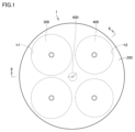
- FIG. 1 is a plan view that illustrates a schematic diagram of an internal combustion engine according to an embodiment.
- 2 is a cross-sectional view taken along line II-II in FIG. 1.
- FIG. 2 is a perspective view of a cavity of the piston.
- FIG. 2 is a plan view illustrating a cavity.
- 4 is a cross-sectional view showing a side shape of a step portion of a cavity in the embodiment.
- FIG. FIG. 4 is a schematic cross-sectional view showing the flow of a spray flame according to the side shape of a cavity in a comparative example.
- 4 is a schematic cross-sectional view showing the flow of a spray flame according to the side shape of a step portion of a cavity in an embodiment.
- 11A to 11C are cross-sectional views showing other forms of step portions of a cavity in an embodiment.
- 11A to 11C are cross-sectional views showing other forms of step portions of a cavity in an embodiment.
- FIG. 4 is a plan view showing the arrangement of step portions of a cavity in the embodiment.
- 13 is a plan view showing another arrangement of the step portion of the cavity in the embodiment.
- FIG. 13 is a plan view showing another arrangement of the step portion of the cavity in the embodiment.
- FIG. 1 is a plan view showing the internal combustion engine 1
- Figure 2 is a cross-sectional view taken along line II-II in Figure 1.
- the internal combustion engine 1 includes a cylinder liner 100, a cylinder head 200, an intake valve 300, an exhaust valve 400, a piston 500, and an injector 600. Although only one cylinder is shown in Figs. 1 and 2, the internal combustion engine 1 can also be applied to a multi-cylinder type.
- the cylinder liner 100 is formed in a cylindrical shape.
- the cylinder head 200 is connected to the end of the cylinder liner 100.
- the cylinder head 200 is formed in a disk shape.
- the cylinder head 200 has an intake port h1 and an exhaust port h2.
- the intake valve 300 opens and closes the intake port h1.
- the intake valve 300 is held in the cylinder head 200.
- the exhaust valve 400 opens and closes the exhaust port h2.
- the exhaust valve 400 is held in the cylinder head 200.
- the piston 500 is capable of moving relative to the cylinder liner 100 along the central axis of the cylinder liner 100 (central axis A in the vertical direction in FIG. 2). As shown in FIG. 2, the piston 500 has a cavity CA formed in a position facing the cylinder head 200.
- the cavity CA has a shape that is recessed from the top surface 504 of the piston 500 in a direction away from the cylinder head 200 (downward in FIG. 2).
- a combustion chamber is formed between the piston 500, which includes the cavity CA, and the cylinder head 200.
- the piston 500 forms a partition wall 502 that partitions the cavity CA.
- the injector 600 is provided in the cylinder head 200 at a position facing the central axis A of the cylinder liner 100.
- the injector 600 injects fuel from the cylinder head 200 toward the cavity CA. More specifically, the injector 600 injects fuel from the center of the combustion chamber to the outside in the radial direction of the cylinder liner 100.
- FIG. 5 is a perspective view of the piston cavity
- Figure 4 is a plan view showing the cavity in a simplified manner.
- the partition wall 502 has a bottom wall 510, a plurality of recess walls 520 arranged at a predetermined pitch along the circumference, and protruding walls 530 extending inward between adjacent recess walls 520.
- the bottom wall 510 faces the injector 600 in the direction of the central axis A of the cylinder liner 100. As shown in FIG. 2, the bottom wall 510 has a shape that gradually slopes away from the cylinder head 200 from the center portion facing the injector 600 in the direction of the central axis A toward the outside in the radial direction.
- the recess wall 520 When viewed along the bottom wall 510, the recess wall 520 has an elliptical shape like a track.
- the recess wall 520 has a shape that is curved so as to be convex outward in the radial direction.
- a plurality of recess walls 520 are arranged in a ring shape at a predetermined pitch in the circumferential direction of the cylinder liner 100.
- the recess walls 520 are formed at a position where they collide with the spray flame B formed by ignition of the fuel injected from the injector 600.
- nine recess walls 520 are arranged in a ring shape in the circumferential direction of the cylinder liner 100, but the number can be set appropriately and is not limited to the number in this embodiment.
- Each protruding wall 530 has a shape that protrudes toward the center of the combustion chamber between adjacent recessed walls 520.
- the number of protruding walls 530 is nine, the same as the number of recessed walls 520.
- Figure 5 is a cross-sectional view showing the side shape of the step portion 550 in the cavity CA
- Figure 6 is a schematic cross-sectional view showing the flow of the spray flame according to the side shape of the cavity CA in a comparative example
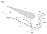
- Figure 7 is a schematic cross-sectional view showing the flow of the spray flame according to the side shape of the step portion 550 in the cavity CA.
- a step portion 550 is provided between the bottom wall 510 (area indicated by S1) and the recess wall 520 (area indicated by S2).
- the step portion 550 is composed of a straight line portion D1 extending from the bottom wall 510 in a direction further away from the cylinder head 200.
- an apex P1 which is a turning point, is provided at the connection portion between the bottom wall 510 and the step portion 550.
- the connection portion between the step portion 550 and the recess wall 520 (opposite side to the apex P1) has a form in which the straight line portion D1 extends in the tangent direction of the recess wall 520.
- the step portion 550 forms an inclined surface that extends (upward) from the outside toward the inside toward the cylinder head 200.
- a curved lip portion R1 extending inward is provided on the opposite side of the step portion 550 of the recess wall 520 (the cylinder head 200 side).
- the length ratio of a first horizontal distance L1 from the central axis A to the step portion 550 of the recess wall 520 and a second horizontal distance L2 including the step portion 550 to the outermost portion P2 of the bottom surface of the recess wall 520 is preferably about 2:1.
- the dimensional ratio is such that the second horizontal distance L2 is smaller than the ratio of about 2:1.
- FIG. 6 shows the flow of the spray flame B according to the side shape in the cavity CA when the conventional step portion is not provided.
- the spray flame B2 that flows along the bottom wall 510 flows toward the center of the cavity CA while contacting the bottom wall 510, which hinders mixing with the air and causes heat to be absorbed by the piston, which is a factor that hinders improvement of combustion efficiency.
- the spray flame B2 flowing along the bottom wall 510 flows along the step portion 550, so that the spray flame B2 is peeled off from the bottom wall 510 (the area surrounded by the dashed line VII in the figure) and heads toward the center of the cavity CA.
- the mixing of the fuel and the remaining air is further promoted, which makes it possible to improve the degree of constant volume, reduce cooling loss, reduce smoke, and improve other combustion efficiency.
- FIGS 8 and 9 are cross-sectional views showing other configurations of the step portion in the cavity CA.
- the step portion 550A shown in Figure 8 is a substantially triangular step portion between the bottom wall 510 and the recess wall 520, with a steep side wall 500w provided on the bottom wall 510 side. Even with this configuration, it is possible to obtain the same effect as the step portion 550 described above.
- the step portion 550B shown in FIG. 9 has a generally tower-like shape that extends upward and has a first side wall 550x that stands on the bottom wall 510 side and a second side wall 550y that drops into the recess wall 520. Even in this form, the same effect as the step portion 550 described above can be obtained.
- Figure 10 is a plan view showing the arrangement of the step portion 550 in the cavity CA
- Figures 11 and 12 are plan views showing other arrangements of the step portion in the cavity CA.
- the step portions 550 in the form shown in FIG. 7 are provided on the bottom wall 510 side in accordance with the arrangement of each recess wall 520, and are therefore arranged in an arc shape on the circumference at a predetermined pitch, as shown in FIG. 10.
- a step portion 550 is also provided on the bottom wall 510 side of the protruding wall 530, and an annular step portion 550C is provided in a plan view, which further promotes mixing of the fuel and remaining air and improves combustion efficiency.
- step portion 550D inside the step portion 550 so as to fill the gaps between the step portions 550 that are spaced apart at a specified pitch on the circumference, it is possible to further promote mixing of the fuel and remaining air and improve combustion efficiency.
- a cylinder liner having a cylindrical inner peripheral surface; a cylinder head connected to the cylinder liner and having an intake port and an exhaust port; an intake valve that opens and closes the intake port; an exhaust valve that opens and closes the exhaust port; a piston that is movable relative to the cylinder liner in a central axis direction of the cylinder liner and has a cavity that forms a combustion chamber at a position facing the cylinder head; an injector that injects fuel from the cylinder head toward the cavity; Equipped with The injector injects the fuel from a center of the combustion chamber to a radially outer side of the cylinder liner,
- the cavity is a bottom wall extending radially outward from a central axis and gradually moving away from the cylinder head; a plurality of recessed walls that are connected to the bottom wall and curved so as to be convex outward in a radial direction; a step portion provided between the bottom wall and the recess wall, The step portion has an arc shape in a
- 1 internal combustion engine 100 cylinder liner, 200 cylinder head, 300 intake valve, 400 exhaust valve, 500 piston, 550, 550A, 550B, 550C, 550D step portion, 500w side wall, 502 partition wall, 504 top surface, 510 bottom wall, 520 recess wall, 530 protruding wall, 550x first side wall, 550y second side wall, 600 injector.
Landscapes
- Engineering & Computer Science (AREA)
- Chemical & Material Sciences (AREA)
- Combustion & Propulsion (AREA)
- Mechanical Engineering (AREA)
- General Engineering & Computer Science (AREA)
- Combustion Methods Of Internal-Combustion Engines (AREA)
Priority Applications (3)
| Application Number | Priority Date | Filing Date | Title |
|---|---|---|---|
| JP2025519343A JPWO2024232194A1 (https=) | 2023-05-11 | 2024-04-02 | |
| AU2024270412A AU2024270412A1 (en) | 2023-05-11 | 2024-04-02 | Internal combustion engine |
| DE112024002044.5T DE112024002044T5 (de) | 2023-05-11 | 2024-04-02 | Verbrennungsmotor |
Applications Claiming Priority (2)
| Application Number | Priority Date | Filing Date | Title |
|---|---|---|---|
| JP2023-078756 | 2023-05-11 | ||
| JP2023078756 | 2023-05-11 |
Publications (1)
| Publication Number | Publication Date |
|---|---|
| WO2024232194A1 true WO2024232194A1 (ja) | 2024-11-14 |
Family
ID=93430201
Family Applications (1)
| Application Number | Title | Priority Date | Filing Date |
|---|---|---|---|
| PCT/JP2024/013634 Ceased WO2024232194A1 (ja) | 2023-05-11 | 2024-04-02 | 内燃機関 |
Country Status (4)
| Country | Link |
|---|---|
| JP (1) | JPWO2024232194A1 (https=) |
| AU (1) | AU2024270412A1 (https=) |
| DE (1) | DE112024002044T5 (https=) |
| WO (1) | WO2024232194A1 (https=) |
Citations (5)
| Publication number | Priority date | Publication date | Assignee | Title |
|---|---|---|---|---|
| JPS5838320A (ja) * | 1981-08-29 | 1983-03-05 | Nissan Motor Co Ltd | 直接噴射式デイ−ゼル機関 |
| JPS62291424A (ja) * | 1986-06-12 | 1987-12-18 | Mitsubishi Motors Corp | 層状燃焼エンジン |
| WO2018167938A1 (ja) * | 2017-03-17 | 2018-09-20 | マツダ株式会社 | ディーゼルエンジン |
| JP2019199825A (ja) * | 2018-05-15 | 2019-11-21 | いすゞ自動車株式会社 | 内燃機関の燃焼室構造 |
| JP2023166161A (ja) * | 2022-05-09 | 2023-11-21 | 株式会社豊田自動織機 | 内燃機関 |
Family Cites Families (1)
| Publication number | Priority date | Publication date | Assignee | Title |
|---|---|---|---|---|
| BRPI0722151B1 (pt) | 2007-10-30 | 2019-10-29 | Volvo Lastvagnar Ab | dispositivo para redução de emissões em um motor de combustão interna de veículo |
-
2024
- 2024-04-02 WO PCT/JP2024/013634 patent/WO2024232194A1/ja not_active Ceased
- 2024-04-02 JP JP2025519343A patent/JPWO2024232194A1/ja active Pending
- 2024-04-02 DE DE112024002044.5T patent/DE112024002044T5/de active Pending
- 2024-04-02 AU AU2024270412A patent/AU2024270412A1/en active Pending
Patent Citations (5)
| Publication number | Priority date | Publication date | Assignee | Title |
|---|---|---|---|---|
| JPS5838320A (ja) * | 1981-08-29 | 1983-03-05 | Nissan Motor Co Ltd | 直接噴射式デイ−ゼル機関 |
| JPS62291424A (ja) * | 1986-06-12 | 1987-12-18 | Mitsubishi Motors Corp | 層状燃焼エンジン |
| WO2018167938A1 (ja) * | 2017-03-17 | 2018-09-20 | マツダ株式会社 | ディーゼルエンジン |
| JP2019199825A (ja) * | 2018-05-15 | 2019-11-21 | いすゞ自動車株式会社 | 内燃機関の燃焼室構造 |
| JP2023166161A (ja) * | 2022-05-09 | 2023-11-21 | 株式会社豊田自動織機 | 内燃機関 |
Also Published As
| Publication number | Publication date |
|---|---|
| AU2024270412A1 (en) | 2026-01-08 |
| JPWO2024232194A1 (https=) | 2024-11-14 |
| DE112024002044T5 (de) | 2026-03-05 |
Similar Documents
| Publication | Publication Date | Title |
|---|---|---|
| US4635597A (en) | Structure of a main combustion chamber of a diesel engine of a direct injection type | |
| CN108474290B (zh) | 内燃机装置及车辆 | |
| US4995359A (en) | Combustion chamber for internal combustion engine | |
| JP2009215978A (ja) | 燃料直噴エンジン | |
| JP7047785B2 (ja) | 圧縮着火エンジン | |
| KR20000068040A (ko) | 직접 분사 스파크 점화식 내연 기관 실린더용 피스톤 | |
| US4538566A (en) | Combustion chamber in a diesel engine | |
| JP4228881B2 (ja) | 筒内噴射式内燃機関 | |
| CN107002548B (zh) | 直喷发动机的燃烧室构造 | |
| JP3982493B2 (ja) | 筒内噴射式内燃機関 | |
| WO2023218742A1 (ja) | 内燃機関 | |
| WO2024232194A1 (ja) | 内燃機関 | |
| JP6519633B2 (ja) | エンジンの燃焼室構造 | |
| JP2020101140A (ja) | 圧縮着火エンジン | |
| JP2004536992A (ja) | 燃焼室 | |
| WO2019044647A1 (ja) | エンジンの燃焼室構造 | |
| EP0828066B1 (en) | Combustion chamber of diesel engine | |
| JPH07317632A (ja) | ディーゼル機関のシリンダカバー | |
| JP3775038B2 (ja) | 筒内噴射式火花点火内燃機関のピストン | |
| JP2011026965A (ja) | 内燃機関 | |
| JP7582281B2 (ja) | 内燃機関の燃焼室構造 | |
| CN104879233A (zh) | 一种直喷式柴油机 | |
| JP7635744B2 (ja) | 副室式エンジン | |
| JP7463311B2 (ja) | 内燃機関 | |
| JP7556272B2 (ja) | エンジンの製造方法 |
Legal Events
| Date | Code | Title | Description |
|---|---|---|---|
| 121 | Ep: the epo has been informed by wipo that ep was designated in this application |
Ref document number: 24803309 Country of ref document: EP Kind code of ref document: A1 |
|
| ENP | Entry into the national phase |
Ref document number: 2025519343 Country of ref document: JP Kind code of ref document: A |
|
| WWE | Wipo information: entry into national phase |
Ref document number: 2025519343 Country of ref document: JP |
|
| WWE | Wipo information: entry into national phase |
Ref document number: AU2024270412 Country of ref document: AU |
|
| WWE | Wipo information: entry into national phase |
Ref document number: 112024002044 Country of ref document: DE |
|
| ENP | Entry into the national phase |
Ref document number: 2024270412 Country of ref document: AU Date of ref document: 20240402 Kind code of ref document: A |
|
| WWP | Wipo information: published in national office |
Ref document number: 112024002044 Country of ref document: DE |