WO2024232176A1 - 模型玩具、及び構造体 - Google Patents
模型玩具、及び構造体 Download PDFInfo
- Publication number
- WO2024232176A1 WO2024232176A1 PCT/JP2024/011816 JP2024011816W WO2024232176A1 WO 2024232176 A1 WO2024232176 A1 WO 2024232176A1 JP 2024011816 W JP2024011816 W JP 2024011816W WO 2024232176 A1 WO2024232176 A1 WO 2024232176A1
- Authority
- WO
- WIPO (PCT)
- Prior art keywords
- model toy
- length
- parts
- assembled
- orientation
- Prior art date
- Legal status (The legal status is an assumption and is not a legal conclusion. Google has not performed a legal analysis and makes no representation as to the accuracy of the status listed.)
- Ceased
Links
Images

Classifications
-
- A—HUMAN NECESSITIES
- A63—SPORTS; GAMES; AMUSEMENTS
- A63H—TOYS, e.g. TOPS, DOLLS, HOOPS OR BUILDING BLOCKS
- A63H3/00—Dolls
-
- A—HUMAN NECESSITIES
- A63—SPORTS; GAMES; AMUSEMENTS
- A63H—TOYS, e.g. TOPS, DOLLS, HOOPS OR BUILDING BLOCKS
- A63H3/00—Dolls
- A63H3/36—Details; Accessories
- A63H3/46—Connections for limbs
Definitions
- the present invention relates to model toys and structures.
- Model toys such as figurines are available in a variety of clothing and hairstyles depending on the modeled subject. Furthermore, each modeled subject has a different physique, with different lengths of limbs and torso. On the other hand, when considering production costs, it is desirable to reuse the same parts as much as possible for characters in the same series, and to be able to accommodate a variety of characters by replacing parts such as clothing and hairstyles.
- Patent Document 1 proposes a technique for shortening or lengthening the skeleton of a joint that forms the skeleton of a doll toy, for example, by connecting a connecting member connected to a lumbar part to a different position on the lumbar part.
- the size of the skeleton is changed by varying the connection positions between parts.
- gaps are generated between the parts that cover the skeleton, such as the torso, giving an unnatural impression.
- the skeleton and the body are represented by a single part, and in such cases it is difficult to form a specific part so that it overlaps with other parts.
- the size of the skeleton can be changed by varying the positions of the screw holes that connect the connecting members, and there is a problem that there are a large number of parts and it is not easy to change to a different body type.
- the present invention provides a new mechanism for changing the size of model toys, for example, using a small number of parts.
- the present invention is, for example, a model toy comprising a first part having a connecting portion, a second part having a receiving portion into which the connecting portion is inserted, and a third part that covers the connection portion between the first part and the second part and regulates the length by which the connecting portion is inserted into the receiving portion, and the third part is characterized in that the regulated length can be changed by changing the orientation in which it is assembled relative to the second part.
- the present invention is also characterized in that, for example, a structure includes a first part having a connecting portion, a second part having a receiving portion into which the connecting portion is inserted, and a third part that covers the connection portion between the first part and the second part and regulates the length by which the connecting portion is inserted into the receiving portion, and the third part changes the regulated length by changing the orientation in which it is assembled relative to the second part.
- the present invention provides a new mechanism for changing the size of model toys using a small number of parts.
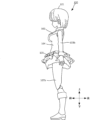
- FIG. 1 is a diagram showing an example of a front appearance of a doll-type toy according to an embodiment.
- FIG. 1 is a diagram showing an example of an exterior side view of a doll-type toy according to an embodiment.
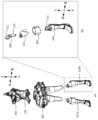
- 1A is an exploded perspective view of a torso portion of a doll-type toy according to one embodiment
- FIG. 1B is an exploded perspective view of a lower leg portion of the doll-type toy according to one embodiment.
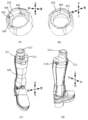
- 1A and 1B are perspective views of clothing parts
- FIG. 1C and 1D are perspective views of lower leg parts of a doll-type toy according to an embodiment.
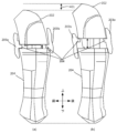
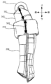
- FIG. 2 is a side cross-sectional view of a lower leg of a doll-type toy according to one embodiment.
- FIG. 13 is a diagram showing the release direction of each part constituting the lower leg of a doll-type toy according to one embodiment from a mold during manufacturing.
- Fig. 1A shows the front appearance of the doll-type toy 100.
- Fig. 1B shows the side appearance of the doll-type toy 100. Note that the up/down, left/right, and front/back arrows indicate the orientation of the doll-type toy in the figure, and this also applies to the other figures.
- the doll toy (doll body) 100 includes a head 101, a chest 102, arms 103a, 103b, an abdomen 104, a waist 105, and legs 107a, 107b.
- the doll toy 100 is a movable doll toy such as a movable figure, and each part can be moved within a limited area caused by its relationship with other members.
- the head 101 is connected to the chest 102 by a spherical connecting member (hereinafter also referred to as a ball joint).
- the chest 102 is further connected to arms 103 including a right arm 103a and a left arm 103b by a spherical connecting member, and is connected to the abdomen 104 at the bottom.
- the waist 105 is connected to the abdomen 104.
- the legs 107 including a right leg 107a and a left leg 107b are connected to the waist 105, and are covered with clothing such as a skirt. Details regarding the lower leg portion of leg 107 will be described later
- the upper body including the head 101, chest 102, and arms 103 is referred to as the upper body.
- the lower body including the waist 105 and legs 107a, 107b is referred to as the lower body.
- the upper body and lower body are connected via the abdomen 104.
- the chest 102, abdomen 104, and waist 105 are also collectively referred to as the torso.
- the structure according to this embodiment will be described mainly as being applied to a part of the limbs, for example the lower leg of the leg 107. However, this is not intended to limit the present invention, and the structure described below can be applied not only to the legs, but also to the arms, torso, neck, etc.
- Figure 2(a) is an exploded perspective view of the chest 102 and abdomen 104, the waist 105 and the upper legs of the legs 107, and the lower legs of the legs 107b.
- Figure 2(b) is an exploded view of the lower legs of the legs 107b.
- the waist 105 is connected to the abdomen 104 by a spherical connecting part (ball joint) so that it can rotate in all directions within a limited range.
- the upper and lower legs of the legs 107a and 107b are rotatably connected by parts 201.
- Figure 2(b) shows the exploded structure of the lower leg of leg 107b, which is surrounded by a dotted line in Figure 2(a).
- the structure of leg 107a is similar to that of leg 107b, so a description of it will be omitted.
- Part 201 is a part that constitutes a knee joint that is connected to the upper thigh of leg 107b.
- a part that constitutes the upper thigh is connected to a ring-shaped connecting part 321 of part 201.
- This allows the lower leg to be rotatably connected to the upper thigh, enabling bending and stretching of leg 107b to be realized.
- rod-shaped connecting part 322 of part 201 passes through hollow parts formed in parts 202 and 203 and is inserted into cylindrical receiving part 313 of part 204. This allows parts 202 and 203 to be assembled to part 204. Therefore, parts 202 and 203 function as spacers that are inserted between parts 201 and 204.
- Part 202 is a part that forms the upper part of the shin of doll-type toy 100, and has a hollow portion formed therein so that connecting part 322 can be inserted.
- the hollow portion is formed to penetrate from one end to the other end so that connecting part 322 can pass through part 202.
- Part 203 is a clothing accessory that is attached to the leg of the doll-type toy, and has a hollow portion into which part 202 with connecting part 322 inserted is inserted. Part 203 is also formed so as to cover the connection portion where parts 201 and 204 are connected. Furthermore, by changing the orientation in which part 203 is assembled relative to part 204, it becomes an adjustment member that changes the length of the lower leg of doll-type toy 100 formed by parts 201 to 204.
- Parts 202 and 204 form the shin of the doll toy 100. Therefore, the width of the gap between the two parts 202 and 204 changes depending on how far the connecting part 322 is inserted into the cavity formed in the receiving part 313. It is desirable that the width of this gap be adjusted so that it is within the range of the ring width of part 203, which is formed in a ring shape and determines the length of the lower leg.
- Figures 3(a) and 3(b) show the configuration of part 203 of the doll-type toy 100 according to this embodiment.
- Figures 3(c) and 3(d) show the configuration of part 204 of the doll-type toy 100 according to this embodiment.
- Figures 3(a) and 3(b) show part 203 upside down. Also, Figure 3(c) shows the front of part 204, and Figure 3(d) shows the back of part 204.
- Part 203 has multiple positioning parts 301-303 and a restricting part 304.
- the restricting part 304 has an inner diameter that is shorter than the inner diameter of part 203 and is formed along the inner wall of part 203.
- the restricting part 304 abuts against the lower end of part 202 that forms the upper shin of doll-type toy 100, and restricts the depth to which the receiving part 313 of part 204 is inserted into the cavity formed in part 202. This further restricts the length to which the connecting part 322 of part 201 is inserted into the receiving part 313 of part 204.
- positioning portion 303 of part 203 fits into fitting portion 314 of part 204 shown in FIG. 3(d), fixing the position of part 203.
- part 203 is assembled to part 204 in the other orientation, which is a state in which the parts are inverted vertically and horizontally as shown in FIG. 3(b)
- positioning portions 301 and 302 of part 203 fit into fitting portions 311 and 312 of part 204 shown in FIG. 3(c).
- the positioning portions 301 and 302 are fitted into the fitting portions 311 and 312, part 203 is fitted shallower into part 204 than when the positioning portion 303 is fitted into fitting portion 314.
- the positioning portion 303 is fitted into fitting portion 314, it is assembled deeper, and parts 202 and 201 are accordingly assembled deeper into part 204. Therefore, the length of the lower leg portion formed by parts 201 to 204 can be shortened compared to when they are fitted shallowly.
- the positioning portions and fitting portions shown in this embodiment are merely examples, and their number and positions may be changed depending on the model toy.
- Figure 4 is a diagram showing a side cross section of the lower leg according to this embodiment.
- Figure 4(a) shows part 203 assembled to part 204 in one orientation as shown in Figure 3(a).
- Figure 4(b) shows part 203 assembled to part 204 in the other orientation as shown in Figure 3(b).
- 203a and 203b each show a cross section of part 203.
- the orientation in which part 203 is assembled to part 204 is reversed top-to-bottom and left-to-right. Note that this is not intended to limit the present invention, and a configuration in which at least only the top-to-bottom is reversed depending on the specifications of the model toy may be used.
- parts 202 and 204 are assembled so as to sandwich restricting portion 304 of part 203. That is, parts 201 and 202 are deeply inserted into part 204. In this case, the gap generated between parts 202 and 204 is approximately the width of restricting portion 304.
- FIG. 4(b) compared to FIG. 4(a), it can be seen that part 203 is assembled upside down and upside down relative to part 204, and that restricting portion 304 is positioned at a higher position. Therefore, part 202 can only be inserted into part 204 up to the position where its lower end abuts restricting portion 304. As a result, as shown in FIG. 4(b), a large gap is secured between parts 202 and 204. The gap shown in FIG. 4(b) changes the length of the lower leg, as shown at 401.
- the length of the lower leg in this embodiment can be changed by reversing the direction in which part 203 is assembled.
- parts 202 and 204 form the shin, if the gap between them is exposed, it gives an unnatural impression.
- these gaps are covered by part 203, which is a clothing part, so it is possible to prevent an unnatural impression.
- the length of the physique can be easily adjusted even in limbs where the skeleton and body are represented by a single part.
- the doll-type toy 100 indicates the direction in which part 202 is released from the mold when it is manufactured.
- 502 indicates the direction in which part 203 is released from the mold when it is manufactured.
- the doll-type toy 100 according to this embodiment is designed so that the abutting parts 202 and 203 are released from the mold in different directions.
- the gap between the parts is designed to be as small as possible even when the parts are assembled upside down.
- parts 202 and 203 function as spacers between parts 201 and 204, and part 201 is fixed by connecting it to part 204.
- the model toy (100) comprises a first part (201) having a connecting portion 322, a second part (204) having a receiving portion 313 into which the connecting portion 322 is inserted, and a third part (203) that covers the connection portion between the first and second parts and regulates the length to which the connecting portion is inserted into the receiving portion.
- the regulated length is changed by changing the orientation in which the third part is assembled relative to the second part.
- the present invention is not limited to the above embodiment, and various modifications and alterations are possible within the scope of the gist of the invention.
- an example was described in which the configuration of the present invention is applied to the lower leg, but it may also be applied to parts of the limbs such as the arms and legs, the neck, tail, abdomen, and waist.
- an example of a doll-type toy was described as a model toy, but the shape of the doll-type toy (doll body) is not particularly limited, and includes various shapes such as humans, animals, robots, insects, dinosaurs, and virtual life forms.
- the shape of the model toy is not particularly limited as long as it includes movable parts.
- a model toy comprising: a first part having a connecting portion; a second part having a receiving portion into which the connecting portion is inserted; and a third part covering the connection portion between the first part and the second part and restricting the length by which the connecting portion is inserted into the receiving portion, the length restricted being changed by changing the orientation of the third part when assembled relative to the second part.
- the model toy described in (5) or (6) characterized in that the first part, the second part, and the fourth part form a part of the limbs of the model toy, and the third part is a clothing part that covers the connecting portion of the first part and the second part.
- the model toy described in any one of (5) to (7) characterized in that the length restricted by the third part is changed to change the length of a part of the limbs of the model toy formed by the first part, the second part, and the fourth part.
- 100 Doll type toy, 101: Head, 102: Chest, 103a, 103b: Arms, 104: Abdomen, 105: Waist, 107a, 107b: Legs
Landscapes
- Toys (AREA)
Abstract
【課題】本発明は、例えば、模型玩具において、少ないパーツで体格のサイズを変更する新規な仕組みを提供する。【解決手段】本模型玩具(100)は、連結部322を有する第1パーツ(201)と、連結部322が挿入される受け入れ部313を有する第2パーツ(204)と、第1パーツと第2パーツとの接続部を被覆し、前記連結部が前記受け入れ部へ挿入される長さを規制する第3パーツ(203)とを備える。第3パーツは第2パーツに 対して組み付ける向きを変更することにより、規制する長さを変更する。
Description
本発明は、模型玩具、及び構造体に関する。
フィギュアなどの模型玩具においては、模型対象に応じて様々な服飾や髪型などに対応するものである。また、模型対象ごとに体格も異なり、四肢や胴体の長さも異なるものである。一方で、製造コスト等を考慮すると、同一シリーズのキャラクターなどにおいては可能な限り同じパーツを流用し、服飾や髪型などのパーツを交換することにより種々のキャラクターに対応可能であることが望ましい。
特許文献1には、人形玩具の骨格を形成する関節において、例えば腰椎パーツに連結される連結部材が当該腰椎パーツの異なる位置に連結されることにより、骨格を縮めたり、延ばしたりする技術が提案されている。
上記従来技術では、パーツ間の連結位置を異ならせることにより骨格のサイズを変更している。しかし、骨格を延ばした状態で連結する場合には、骨格を覆う胴体等のパーツ間に隙間が生じ不自然な印象を与えてしまう。一方で、隙間が生じないように胴体等のパーツを大きめに形成することも考えられるが、その場合において骨格を縮めた状態で連結すると、胴体等を形成するパーツ間で重なる部分が生じ不自然な印象を与えてしまう。また、四肢などの空間的に狭い部位では骨格と肉体とが1つのパーツで表現されるものであり、そのような場合には所定のパーツが他のパーツと重なるように形成することは困難なものである。さらに、上記従来技術では、連結部材を連結するネジ穴の位置を異ならせることにより骨格のサイズを変更可能としており、部品の点数が多く、他の体格への変更が容易でないという問題がある。
本発明は、例えば、模型玩具において、少ないパーツでサイズを変更する新規な仕組みを提供する。
本発明は、例えば、模型玩具であって、連結部を有する第1パーツと、前記連結部が挿入される受け入れ部を有する第2パーツと、前記第1パーツと前記第2パーツとの接続部を被覆し、前記連結部が前記受け入れ部へ挿入される長さを規制する第3パーツとを備え、前記第3パーツは前記第2パーツに対して組み付ける向きを変更することにより、規制する前記長さを変更することを特徴とする。
また、本発明は、例えば、構造体であって、連結部を有する第1パーツと、前記連結部が挿入される受け入れ部を有する第2パーツと、前記第1パーツと前記第2パーツとの接続部を被覆し、前記連結部が前記受け入れ部へ挿入される長さを規制する第3パーツとを備え、前記第3パーツは前記第2パーツに対して組み付ける向きを変更することにより、規制する前記長さを変更することを特徴とする。
本発明によれば、模型玩具において、少ないパーツでサイズを変更する新規な仕組みを提供することができる。
以下、添付図面を参照して実施形態を詳しく説明する。尚、以下の実施形態は特許請求の範囲に係る発明を限定するものではなく、また実施形態で説明されている特徴の組み合わせの全てが発明に必須のものとは限らない。実施形態で説明されている複数の特徴うち二つ以上の特徴が任意に組み合わされてもよい。また、同一若しくは同様の構成には同一の参照番号を付し、重複した説明は省略する。
<人形型玩具の外観> まず、図1A及び図1Bを参照して、本実施形態に係る人形型玩具100の外観構成の一例について説明する。図1Aは人形型玩具100の外観正面を示す。図1Bは人形型玩具100の外観側面を示す。なお、上下、左右、前後の矢印については図における人形型玩具の向きを示し、他の図面についても同様である。
人形型玩具(人形体)100は、頭部101、胸部102、腕部103a、103b、腹部104、腰部105、及び脚部107a、107bを備える。人形型玩具100は、可動フィギアなどの可動式の人形型玩具であり、各パーツは他の部材との関係で生じる制限領域の範囲内で可動させることができる。頭部101は胸部102に球形状の連結部材によって連結される(以下では、ボールジョイントとも称する。)。胸部102には、さらに右腕部103a及び左腕部103bを含む腕部103が球形状の連結部材で連結され、下部において腹部104が連結される。腹部104には腰部105が連結される。腰部105には右脚部107a及び左脚部107bを含む脚部107が連結され、スカート等の服飾部で覆われる。脚部107の下腿部についての詳細については後述する。
なお、以下では、頭部101、胸部102、及び腕部103を含む上半身を上体部と称する。また、腰部105、脚部107a、107bを含む下半身を下体部と称する。上体部及び下体部は腹部104を介して連結される。また、胸部102、腹部104、及び腰部105をまとめて胴体部とも称する。以下では、本実施形態に係る構造体として、主に四肢の一部、例えば脚部107の下腿部に適用される場合について説明する。しかしながら、本発明を限定する意図はなく、以下で説明する構造体は、脚部に限らず、腕部や、胴体部、首部などに適用することも可能である。
<脚部の構成> 次に、図2を参照して、本実施形態に係る人形型玩具100の脚部107を中心とした付近の詳細構成ついて説明する。図2(a)は胸部102及び腹部104と、腰部105及び脚部107の上腿部と、脚部107の下腿部とを分解した斜視図である。図2(b)は脚部107bの下腿部を分解した分解図である。
図2(a)に示すように、腰部105は腹部104に対して連結されるものであり、球形状の連結部(ボールジョイント)で制限の範囲内で全方向に回動可能に連結される。また、脚部107a、107bでは、それぞれ上腿部と下腿部とがパーツ201によって回転可能に連結される。
図2(b)は図2(a)の点線で囲まれた脚部107bの下腿部の分解構成を示す。脚部107aの構成は脚部107bと同様の構成であるため説明を省略する。
パーツ201は脚部107bの上腿部に接続される膝関節を構成するパーツである。パーツ201のリング形状の連結部321に上腿部を構成するパーツが連結される。これにより、上腿部に対して下腿部が回転可能に連結され、脚部107bの屈伸動作を実現することができる。また、パーツ201の棒形状の連結部322は、パーツ202、203に形成された空洞部を通過して、パーツ204の円筒形状の受け入れ部313に挿入される。これにより、パーツ202及びパーツ203をパーツ204に組み付けることができる。したがって、パーツ202及びパーツ203は、パーツ201とパーツ204と間に挿入されるスペーサとして機能するパーツである。
パーツ202は、人形型玩具100の脛部の上部を形成するパーツであり、連結部322が挿入されるように内部に空洞部が形成されている。また連結部322がパーツ202を介して通過するように、当該空洞部は、一方の端部から他方の端部まで貫通して形成されている。
パーツ203は、人形型玩具の脚部に装着される服飾部であり、連結部322が挿入されたパーツ202が挿入される空洞部が形成されている。また、パーツ203は、パーツ201とパーツ204とが接続される接続部を被覆するように形成される。さらに、パーツ203はパーツ204に対して組み付ける向きを変更することにより、パーツ201~204で形成される人形型玩具100の下腿部の長さを変更する調整部材となる。
パーツ202及びパーツ204は、人形型玩具100の脛部を形成する。したがって、連結部322が受け入れ部313に形成された空洞部のどの部分まで挿入されるかに応じて、2つのパーツ202、204の間に生じる隙間の幅が変化することとなる。この隙間の幅は、下腿部の長さを規定し、リング形状で形成されたパーツ203のリング幅の範囲内となるように調整されることが望ましい。
<体格を調整するパーツの構成> 次に、図3を参照して、本実施形態に係る人形型玩具100の体格を調整するパーツの構成について説明する。図3(a)及び図3(b)は本実施形態に係る人形型玩具100のパーツ203の構成を示す。図3(c)及び図3(d)は本実施形態に係る人形型玩具100のパーツ204の構成を示す。
図3(a)及び図3(b)は互いにパーツ203の上下を逆さにした図を示す。また、図3(c)はパーツ204の正面を示し、図3(d)はパーツ204の背面を示す。パーツ203は複数の位置決め部301~303と、規制部304を有する。規制部304は、パーツ203の内径よりもさらに短い内径で、パーツ203の内壁に沿って形成される。当該規制部304は、人形型玩具100の脛上を形成するパーツ202の下端部に当接し、当該パーツ202に形成された空洞部にパーツ204の受け入れ部313が挿入される深さを規制する。これにより、さらにパーツ201の連結部322がパーツ204の受け入れ部313に挿入される長さを規制することができる。
図3(a)に示すように、一方の向きでパーツ203がパーツ204に対して組み付けられる場合は、パーツ203の位置決め部303が図3(d)に示すパーツ204の嵌め込み部314に嵌合され、パーツ203の位置を固定する。一方、図3(b)に示すように上下左右を反転させた状態となる他方の向きでパーツ203がパーツ204に対して組み付けられる場合は、パーツ203の位置決め部301、302が図3(c)に示すパーツ204の嵌め込み部311、312に嵌合される。
位置決め部301、302が嵌め込み部311、312に嵌合される場合は、位置決め部303が嵌め込み部314に嵌合される場合と比較して、パーツ203はパーツ204に対して浅く嵌め込まれることになる。言い換えれば、位置決め部303が嵌め込み部314に嵌合される場合はより深く組み付けられ、これに応じてパーツ202、201もパーツ204に対して深く組み付けられることとなる。したがって、浅く嵌め込まれる場合と比較して、パーツ201~204で形成される下腿部の長さを短くすることができる。なお、本実施形態で示す位置決め部や嵌め込み部については単なる一例であり、その数や形成される位置については、模型玩具に応じて変更されるものであってよい。
<下腿部の側断面> 図4は本実施形態に係る下腿部の側断面を示す図である。図4(a)はパーツ203を図3(a)に示す一方の向きでパーツ204に対して組み付けた様子を示す。図4(b)はパーツ203を図3(b)に示す他方の向きでパーツ204に対して組み付けた様子を示す。203a、203bはそれぞれパーツ203の断面を示す。つまり、図4(a)と図4(b)とにおいて、パーツ203がパーツ204に対して組み付けられる向きは、上下左右が反転した状態となる。なお、本発明を限定する意図はなく、模型玩具の仕様に応じて、少なくとも上下のみを反転させる構成としてもよい。
図4(a)では、パーツ202とパーツ204とがパーツ203の規
制部304を挟み込むように組み付けられていることがわかる。即ち、パーツ201及びパーツ202がパーツ204に対して深く挿入されている状態となる。この場合、パーツ202と、パーツ204との間に生じる隙間は規制部304の幅程度となる。
制部304を挟み込むように組み付けられていることがわかる。即ち、パーツ201及びパーツ202がパーツ204に対して深く挿入されている状態となる。この場合、パーツ202と、パーツ204との間に生じる隙間は規制部304の幅程度となる。
一方、図4(b)では、図4(a)と比較して、パーツ203がパーツ204に対して上下左右を反転して組み付けられ、規制部304がより高い位置に位置づけられていることがわかる。したがって、パーツ202は、その下端部が当該規制部304に対して当接する位置までしかパーツ204に対して挿入することができない。よって、図4(b)に示すように、パーツ202とパーツ204との間の隙間が大きく確保されることとなる。図4(b)に示す隙間は、401に示すように、下腿部の長さを変更することになる。
このように、本実施形態に係る下腿部は、パーツ203を組み付ける向きを逆方向にすることで、その長さを変更することができる。なお、パーツ202とパーツ204とは脛部を形成するパーツであるため、それらの間に生じた隙間が露出すると不自然な印象を与えてしまう。しかし、本実施形態によれば、これらの隙間は服飾部であるパーツ203によって被覆されているため、不自然な印象を与えないようにすることができる。このように、本実施形態によれば、骨格と肉体とが一つのパーツで表現される四肢などにおいても容易に体格の長さを調整することができる。
<金型からの離型方向 > 次に、図5を参照して、本実施形態に係る下腿部を構成する各パーツの製造時における金型から成形品(各パーツ)を取り出す離型方向について説明する。図5は下腿部の側面図を示す。
501はパーツ202の製造時における金型からの離型方向を示す。502はパーツ203の製造時における金型からの離型方向を示す。このように、本実施形態に係る人形型玩具100では、当接するパーツ202、203の金型からの離型方向を異ならせるように設計している。
一方で、パーツ202にパーツ203を接続して固定するパーツ構成の場合、パーツ202とパーツ203とは同じ方向で金型から離型させることが一般的に行われている。これにより、パーツ202とパーツ203を組み付けた際に十分な強度で固定することができる。しかし、本実施形態では、パーツ203を上下反転させて使用する場合も想定しており、そのように設計されたパーツ同士では、上下反転させる組み付けた場合にパーツ203とパーツ202との間に不自然な隙間が生じてしまう。
したがって、本実施形態では、パーツ202とパーツ203との金型からの離型方向を異ならせることによって、上下を反転させて組み付けた場合であっても、パーツ間で生じる隙間をできる限り小さく設計している。一方で、パーツ同士を組み付けた際に固定する強度が十分得られないため、パーツ202、203はパーツ201、204の間のスペーサのようなパーツとして機能させ、パーツ201がパーツ204へ連結されることによって固定されるようにしている。
以上説明したように、本実施形態に係る模型玩具(100)は、連結部322を有する第1パーツ(201)と、連結部322が挿入される受け入れ部313を有する第2パーツ(204)と、第1パーツと第2パーツとの接続部を被覆し、前記連結部が前記受け入れ部へ挿入される長さを規制する第3パーツ(203)とを備える。第3パーツは第2パーツに対して組み付ける向きを変更することにより、規制する長さを変更する。これにより、本実施形態によれば、例えば、模型玩具において、少ないパーツで体格のサイズを変更する新規な仕組みを提供することができる。
<変形例> 本発明は上記実施形態に制限されるものではなく、発明の要旨の範囲内で、種々の変形・変更が可能である。上記実施形態では、本発明の構成を下腿部分に適用する例について説明したが、腕部や脚部の四肢の一部や、首部、尾部、腹部、腰部などにも適用してもよい。また、上記実施形態では、模型玩具として人形型玩具の例を説明したが、人形型玩具(人形体)の形状は、特に限定されるものではなく、人、動物、ロボット、昆虫、恐竜、仮想生命体等、様々な形状を含むものである。また、可動部を含む形態であれば、模型玩具の形状は特に限定されるものではない。
<実施形態のまとめ> 上記実施形態は以下の模型玩具、及び構造体を少なくとも開示する。(1)模型玩具であって、 連結部を有する第1パーツと、 前記連結部が挿入される受け入れ部を有する第2パーツと、 前記第1パーツと前記第2パーツとの接続部を被覆し、前記連結部が前記受け入れ部へ挿入される長さを規制する第3パーツとを備え、 前記第3パーツは前記第2パーツに対して組み付ける向きを変更することにより、規制する前記長さを変更することを特徴とする模型玩具。(2)前記第3パーツは、リング形状で形成され、円筒形状の前記連結部に対して前記リング形状のリングを挿入する方向を変更することにより、前記第3パーツを前記第2パーツに対して組み付ける向きを変更することを特徴とする(1)に記載の模型玩具。(3)前記第3パーツはリングの内壁に第1位置決め部及び第2位置決め部を有し、 前記第2パーツは、前記第1位置決め部に嵌め込まれる第1嵌め込み部と、前記第2位置決め部に嵌め込まれる第2嵌め込み部とを有し、 前記第3パーツを前記第2パーツに対して組み付ける向きを第1方向とする場合は、前記第1位置決め部と前記第1嵌め込み部とが嵌合し、 前記第3パーツを前記第2パーツに対して組み付ける向きを前記第1方向とは逆方向となる第2方向とする場合は、前記第2位置決め部と前記第2嵌め込み部とが嵌合することを特徴とする(2)に記載の模型玩具。(4)前記第3パーツによって規制する前記長さの範囲は前記リング形状のリング幅の範囲内であることを特徴とする(2)又は(3)に記載の模型玩具。(5)前記第1パーツと前記第2パーツとの間に挟み込まれる第4パーツをさらに備え、 前記連結部は前記第3パーツ及び前記第4パーツを介して前記受け入れ部へ挿入されることを特徴とする(1)乃至(4)の何れか1つに記載の模型玩具。(6)前記第3パーツはリングの内壁に沿って形成される規制部を有し、 前記規制部は、前記第2パーツと前記第4パーツとの間に挟まれて、前記第4パーツの位置を規定し、前記第1パーツの前記連結部が前記第2パーツの前記受け入れ部へ挿入される長さを規制することを特徴とする(5)に記載の模型玩具。(7)前記第1パーツ、前記第2パーツ、及び前記第4パーツは前記模型玩具の四肢の一部を形成し、 前記第3パーツは、前記第1パーツ及び前記第2パーツの接続部を被覆する服飾部であることを特徴とする(5)又は(6)に記載の模型玩具。(8)前記第3パーツによって規制する前記長さを変更することによって、前記第1パーツ、前記第2パーツ、及び前記第4パーツによって形成される前記模型玩具の四肢の一部の長さが変更されることを特徴とする(5)乃至(7)の何れか1つに記載の模型玩具。(9)前記第3パーツと、前記第4パーツとは、それぞれ金型からの離型方向が異なるように形成されることを特徴とする(5)乃至(8)の何れか1つに記載の模型玩具。(10) 前記第3パーツと前記第4パーツは、前記第1パーツが前記第2パーツに連結されることにより固定されることを特徴とする(5)に記載の模型玩具(11)構造体であって、 連結部を有する第1パーツと、 前記連結部が挿入される受け入れ部を有する第2パーツと、 前記第1パーツと前記第2パーツとの接続部を被覆し、前記連結部が前記受け入れ部へ挿入される長さを規制する第3パーツとを備え、 前記第3パーツは前記第2パーツに対して組み付ける向きを変更することにより、規制する前記長さを変更することを特徴とする構造体。
100:人形型玩具、101:頭部、102:胸部、103a、103b:腕部、104:腹部、105:腰部、107a、107b:脚部
Claims (11)
- 模型玩具であって、 連結部を有する第1パーツと、 前記連結部が挿入される受け入れ部を有する第2パーツと、 前記第1パーツと前記第2パーツとの接続部を被覆し、前記連結部が前記受け入れ部へ挿入される長さを規制する第3パーツとを備え、 前記第3パーツは前記第2パーツに対して組み付ける向きを変更することにより、規制する前記長さを変更することを特徴とする模型玩具。
- 前記第3パーツは、リング形状で形成され、円筒形状の前記連結部に対して前記リング形状のリングを挿入する方向を変更することにより、前記第3パーツを前記第2パーツに対して組み付ける向きを変更することを特徴とする請求項1に記載の模型玩具。
- 前記第3パーツはリングの内壁に第1位置決め部及び第2位置決め部を有し、 前記第2パーツは、前記第1位置決め部に嵌め込まれる第1嵌め込み部と、前記第2位置決め部に嵌め込まれる第2嵌め込み部とを有し、 前記第3パーツを前記第2パーツに対して組み付ける向きを第1方向とする場合は、前記第1位置決め部と前記第1嵌め込み部とが嵌合し、 前記第3パーツを前記第2パーツに対して組み付ける向きを前記第1方向とは逆方向となる第2方向とする場合は、前記第2位置決め部と前記第2嵌め込み部とが嵌合することを特徴とする請求項2に記載の模型玩具。
- 前記第3パーツによって規制する前記長さの範囲は前記リング形状のリング幅の範囲内であることを特徴とする請求項2又は3に記載の模型玩具。
- 前記第1パーツと前記第2パーツとの間に挟み込まれる第4パーツをさらに備え、 前記連結部は前記第3パーツ及び前記第4パーツを介して前記受け入れ部へ挿入されることを特徴とする請求項1に記載の模型玩具。
- 前記第3パーツはリングの内壁に沿って形成される規制部を有し、 前記規制部は、前記第2パーツと前記第4パーツとの間に挟まれて、前記第4パーツの位置を規定し、前記第1パーツの前記連結部が前記第2パーツの前記受け入れ部へ挿入される長さを規制することを特徴とする請求項5に記載の模型玩具。
- 前記第1パーツ、前記第2パーツ、及び前記第4パーツは前記模型玩具の四肢の一部を形成し、 前記第3パーツは、前記第1パーツ及び前記第2パーツの接続部を被覆する服飾部であることを特徴とする請求項6に記載の模型玩具。
- 前記第3パーツによって規制する前記長さを変更することによって、前記第1パーツ、前記第2パーツ、及び前記第4パーツによって形成される前記模型玩具の四肢の一部の長さが変更されることを特徴とする請求項7に記載の模型玩具。
- 前記第3パーツと、前記第4パーツとは、それぞれ金型からの離型方向が異なるように形成されることを特徴とする請求項5に記載の模型玩具。
- 前記第3パーツと前記第4パーツは、前記第1パーツが前記第2パーツに連結されることにより固定されることを特徴とする請求項5に記載の模型玩具。
- 構造体であって、 連結部を有する第1パーツと、 前記連結部が挿入される受け入れ部を有する第2パーツと、 前記第1パーツと前記第2パーツとの接続部を被覆し、前記連結部が前記受け入れ部へ挿入される長さを規制する第3パーツとを備え、 前記第3パーツは前記第2パーツに対して組み付ける向きを変更することにより、規制する前記長さを変更することを特徴とする構造体。
Applications Claiming Priority (2)
| Application Number | Priority Date | Filing Date | Title |
|---|---|---|---|
| JP2023077352A JP7366305B1 (ja) | 2023-05-09 | 2023-05-09 | 模型玩具、及び模型玩具の構造体 |
| JP2023-077352 | 2023-05-09 |
Publications (1)
| Publication Number | Publication Date |
|---|---|
| WO2024232176A1 true WO2024232176A1 (ja) | 2024-11-14 |
Family
ID=88372782
Family Applications (1)
| Application Number | Title | Priority Date | Filing Date |
|---|---|---|---|
| PCT/JP2024/011816 Ceased WO2024232176A1 (ja) | 2023-05-09 | 2024-03-26 | 模型玩具、及び構造体 |
Country Status (3)
| Country | Link |
|---|---|
| JP (2) | JP7366305B1 (ja) |
| CN (1) | CN117695680A (ja) |
| WO (1) | WO2024232176A1 (ja) |
Families Citing this family (1)
| Publication number | Priority date | Publication date | Assignee | Title |
|---|---|---|---|---|
| JP7760789B1 (ja) * | 2025-05-13 | 2025-10-27 | 株式会社バンダイ | 模型玩具、及び模型部品 |
Citations (6)
| Publication number | Priority date | Publication date | Assignee | Title |
|---|---|---|---|---|
| JPS61176379A (ja) * | 1985-01-29 | 1986-08-08 | 株式会社 タカラ | 形態変化玩具 |
| JPH07241387A (ja) * | 1994-01-13 | 1995-09-19 | Bandai Co Ltd | 人形玩具の頭部回転装置 |
| JP2005211688A (ja) * | 2005-04-18 | 2005-08-11 | Sente Creations:Kk | 人形玩具 |
| CN201565128U (zh) * | 2009-11-30 | 2010-09-01 | 万代贸易(广州)有限公司 | 一种组合式机器人玩偶 |
| WO2014129065A1 (ja) * | 2013-02-22 | 2014-08-28 | 株式会社バンダイ | 人形体 |
| JP2022111363A (ja) * | 2020-11-13 | 2022-07-29 | 株式会社バンダイ | 腕構造及び人型玩具 |
-
2023
- 2023-05-09 JP JP2023077352A patent/JP7366305B1/ja active Active
- 2023-10-06 JP JP2023174615A patent/JP2024162962A/ja active Pending
- 2023-12-25 CN CN202311790703.4A patent/CN117695680A/zh active Pending
-
2024
- 2024-03-26 WO PCT/JP2024/011816 patent/WO2024232176A1/ja not_active Ceased
Patent Citations (6)
| Publication number | Priority date | Publication date | Assignee | Title |
|---|---|---|---|---|
| JPS61176379A (ja) * | 1985-01-29 | 1986-08-08 | 株式会社 タカラ | 形態変化玩具 |
| JPH07241387A (ja) * | 1994-01-13 | 1995-09-19 | Bandai Co Ltd | 人形玩具の頭部回転装置 |
| JP2005211688A (ja) * | 2005-04-18 | 2005-08-11 | Sente Creations:Kk | 人形玩具 |
| CN201565128U (zh) * | 2009-11-30 | 2010-09-01 | 万代贸易(广州)有限公司 | 一种组合式机器人玩偶 |
| WO2014129065A1 (ja) * | 2013-02-22 | 2014-08-28 | 株式会社バンダイ | 人形体 |
| JP2022111363A (ja) * | 2020-11-13 | 2022-07-29 | 株式会社バンダイ | 腕構造及び人型玩具 |
Also Published As
| Publication number | Publication date |
|---|---|
| CN117695680A (zh) | 2024-03-15 |
| JP2024162123A (ja) | 2024-11-21 |
| JP2024162962A (ja) | 2024-11-21 |
| JP7366305B1 (ja) | 2023-10-20 |
Similar Documents
| Publication | Publication Date | Title |
|---|---|---|
| JP7699079B2 (ja) | 人形型玩具、及び関節構造 | |
| JP2023133095A (ja) | 模型玩具、及び可動構造 | |
| WO2024232176A1 (ja) | 模型玩具、及び構造体 | |
| JP6030615B2 (ja) | 人形玩具の肩関節構造及び人形玩具 | |
| JP2019030684A (ja) | 人形玩具の肩関節構造及び人形玩具 | |
| JP7168805B1 (ja) | 模型玩具、及び可動構造 | |
| JP2025063887A (ja) | 模型玩具、及び可動構造体 | |
| JP7460840B1 (ja) | 模型玩具、及び構造体 | |
| JP7223909B1 (ja) | 模型玩具、及び可動構造体 | |
| WO2024232174A1 (ja) | 模型玩具、及び可動構造体 | |
| CN114534267B (zh) | 人形状玩具和模型的连结构件 | |
| JP7098040B1 (ja) | 人形体、及び関節構造 | |
| JP7784019B1 (ja) | 模型玩具、及び模型部品 | |
| JP6411429B2 (ja) | 人形玩具の肩関節構造及び人形玩具 | |
| JP7587667B1 (ja) | 模型玩具 | |
| JP7760789B1 (ja) | 模型玩具、及び模型部品 | |
| CN223464420U (zh) | 拼装玩具的肢体组件和拼装玩具 | |
| JP2023055933A (ja) | 人形型玩具、及び模型の服飾部材 | |
| JP2025074747A (ja) | 模型玩具、及び可動構造体 | |
| JP2025026725A5 (ja) | ||
| CN120789670A (zh) | 模型玩具和模型部件 | |
| JP2021041218A (ja) | 人形玩具の肩関節構造及び人形玩具 |
Legal Events
| Date | Code | Title | Description |
|---|---|---|---|
| 121 | Ep: the epo has been informed by wipo that ep was designated in this application |
Ref document number: 24803291 Country of ref document: EP Kind code of ref document: A1 |
|
| NENP | Non-entry into the national phase |
Ref country code: DE |