WO2024232174A1 - 模型玩具、及び可動構造体 - Google Patents
模型玩具、及び可動構造体 Download PDFInfo
- Publication number
- WO2024232174A1 WO2024232174A1 PCT/JP2024/011814 JP2024011814W WO2024232174A1 WO 2024232174 A1 WO2024232174 A1 WO 2024232174A1 JP 2024011814 W JP2024011814 W JP 2024011814W WO 2024232174 A1 WO2024232174 A1 WO 2024232174A1
- Authority
- WO
- WIPO (PCT)
- Prior art keywords
- movable
- parts
- model toy
- connecting portion
- movable mechanism
- Prior art date
- Legal status (The legal status is an assumption and is not a legal conclusion. Google has not performed a legal analysis and makes no representation as to the accuracy of the status listed.)
- Ceased
Links
Images

Classifications
-
- A—HUMAN NECESSITIES
- A63—SPORTS; GAMES; AMUSEMENTS
- A63H—TOYS, e.g. TOPS, DOLLS, HOOPS OR BUILDING BLOCKS
- A63H3/00—Dolls
-
- A—HUMAN NECESSITIES
- A63—SPORTS; GAMES; AMUSEMENTS
- A63H—TOYS, e.g. TOPS, DOLLS, HOOPS OR BUILDING BLOCKS
- A63H3/00—Dolls
- A63H3/36—Details; Accessories
- A63H3/46—Connections for limbs
Definitions
- the present invention relates to model toys and movable structures.
- Doll toys (model toys) are required to be able to move naturally and have a wide variety of poses. Therefore, to realize movements and poses similar to those of humans and animals, doll toys include various joints and movable parts.
- Patent Document 1 proposes a four-legged animal doll that has a joint structure that allows realistic movements similar to those of real animals.
- the present invention provides a novel mechanism for realizing a moving mechanism that performs movements with a natural appearance.
- the present invention is, for example, a model toy comprising a first part that serves as the base of multiple movable shafts having a spherical first connecting portion and a second connecting portion formed at one end, a second part that has a first connection portion that rotatably receives the first connecting portion, and a third part that has a second connection portion at one end that is rotatably connected to the second connecting portion, wherein a first movable mechanism of the model toy is formed by the first connecting portion and the first connection portion, and a second movable mechanism of the model toy that includes a movable shaft different from the first movable mechanism is formed by the second connecting portion and the second connection portion.
- the present invention also provides, for example, a movable structure comprising a first part that serves as a base for a plurality of movable shafts having a spherical first connecting portion and a second connecting portion formed at one end, a second part that has a first connection portion that rotatably receives the first connecting portion, and a third part that has a second connection portion at one end that is rotatably connected to the second connecting portion, wherein the first connecting portion and the first connection portion form a first movable mechanism of the movable structure, and the second connecting portion and the second connection portion form a second movable mechanism of the movable structure that includes a movable shaft different from the first movable mechanism.
- the present invention provides a novel mechanism that realizes a movable mechanism that operates in a natural way.
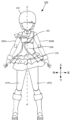
- FIG. 1 is a diagram showing an example of a front appearance of a doll-type toy according to an embodiment.
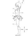
- FIG. 1 is a diagram showing an example of an exterior side view of a doll-type toy according to an embodiment.
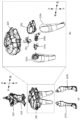
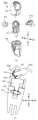
- 1A is an exploded perspective view of a torso portion of a doll-type toy according to one embodiment
- FIG. 1B is an exploded perspective view of a waist portion of the doll-type toy according to one embodiment.
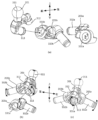
- FIG. 11 is an assembly diagram of a second movable mechanism of the doll-type toy according to one embodiment.
- 1A is an exploded view of a first movable mechanism of a doll-type toy according to one embodiment
- FIG. 1B is a plan view of the first movable mechanism
- FIG. 2 is an exploded perspective view of a leg of the doll-type toy according to one embodiment.
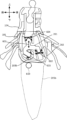
- FIG. 2 is a cross-sectional view of the body of the doll-type toy according to one embodiment.
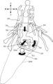
- 1A to 1C are cross-sectional views showing the operation of the lower body of a doll-type toy according to one embodiment.
- Fig. 1A shows the front appearance of the doll-type toy 100.
- Fig. 1B shows the side appearance of the doll-type toy 100. Note that the up/down, left/right, and front/back arrows indicate the orientation of the doll-type toy in the figure, and this also applies to the other figures.
- the doll toy (doll body) 100 includes a head 101, a chest 102, arms 103a, 103b, an abdomen 104, a waist 105, and legs 107a, 107b.
- the doll toy 100 is a movable doll toy such as a movable figure, and each part can be moved within a limited range caused by its relationship with other members.
- the head 101 is connected to the chest 102 by a spherical connecting member (hereinafter, also referred to as a ball joint).
- the chest 102 is further connected to arms 103 including a right arm 103a and a left arm 103b by a spherical connecting member, and is connected to the abdomen 104 at the bottom.
- the detailed structure of the chest will be described later.
- the waist 105 is connected to the abdomen 104.
- the legs 107 including the right leg 107a and the left leg 107b are connected to the waist 105, and are covered with clothing such as a skirt.
- the upper body including the head 101, chest 102, and arms 103 is referred to as the upper body.
- the lower body including the waist 105 and legs 107a, 107b is referred to as the lower body.
- the upper body and lower body are connected via the abdomen 104.
- the chest 102, abdomen 104, and waist 105 are also collectively referred to as the torso.
- the structures of the waist joint and hip joint are mainly described as the movable structure according to this embodiment. However, this is not intended to limit the present invention, and the movable structure described below is not limited to the waist joint and hip joint, but can also be applied to other joints, such as shoulder joints and chest joints that connect arms.
- FIG. 2(a) is an exploded perspective view of the chest 102 and abdomen 104, the waist 105 and the upper leg portion of the leg 107, and the lower leg portion of the leg 107.
- Figure 2(b) is an exploded view of the waist 105, including the waist joint and hip joint, and parts of the legs 107a and 107b.
- the waist 105 is connected to the abdomen 104 by a spherical connecting portion (ball joint) of part 201 shown in FIG. 2(b).
- the waist joint according to this embodiment connects the waist 105 to the abdomen 104 rotatably by a ball joint.
- this is not intended to limit the invention, and connecting portions of other shapes may be used in place of the spherical connecting portion.
- FIG. 2(b) shows the disassembled structure of the waist 105 and the upper thigh portion of the leg 107 surrounded by a dotted line in Figure 2(a).
- the waist 105 is composed of at least a plurality of parts 201 to 204.
- Part 201 is a part (first part) that serves as the base of a plurality of moving mechanisms.
- Part 202 (second part) is rotatably connected to part 201.
- Part 202 constitutes part of the waist and part of the clothing of the doll-type toy 100. Therefore, in the doll-type toy 100 according to this embodiment, part of the waist and part of the clothing move on an axis that is independent of other moving mechanisms and other parts.
- Each of the parts 203a and 203b is sequentially connected to a cylindrical portion formed at one end of the part 201. This forms the hip joint of the doll-type toy 100.
- Parts 205a and 205b which are the upper thigh portions of the legs 107a and 107b, are further connected to the parts 203a and 203, respectively.
- the parts group formed by assembling the parts 201, 202, 203a and 203b is covered with the part 204, which represents a skirt or the like that is part of the clothing of the doll-type toy 100.
- the parts 201, 202, 203a and 203b are inserted from the bottom of the part 204, and the spherical connecting portion of the part 201 is rotatably connected to the part that constitutes the abdomen 104, forming the waist joint movable mechanism.
- part 201 which serves as the base of the multiple moving mechanisms, is connected to other parts to realize the moving mechanism of part 202 (first moving mechanism), the moving mechanism of the hip joint (second moving mechanism), and the moving mechanism of the waist joint (third moving mechanism).
- first moving mechanism the moving mechanism of part 202
- second moving mechanism the moving mechanism of the hip joint
- third moving mechanism the moving mechanism of the waist joint
- this embodiment makes it possible to effectively utilize the open areas of the two openings of part 202 into which the connecting parts to the hip joints of parts 205a and 205b, which form part of legs 107a and 107b, are inserted.
- the cylindrical parts of parts 203a and 203b to which parts 205a and 205b are connected also rotate in conjunction with each other, and it is possible to obtain a movable range that makes maximum use of the open areas of the openings.
- the rotation of part 201 relative to part 204 can further expand the movable range. Therefore, more natural movements and a variety of poses can be realized. Details of the movements will be described later.
- Figures 3(a) and 3(b) show the assembled configuration of the second movable mechanism according to this embodiment.
- Figure 3(c) shows an example of the operation performed by the second movable mechanism according to this embodiment.
- part 201 includes a spherical connecting part 311 that is connected to a part of abdomen 104 to form a waist joint, a spherical connecting part 312 that is connected to part 202, and a cylindrical (or rod-shaped) connecting part 313 for forming a hip joint.
- Parts 203a and 203b also have ring-shaped connecting parts 331a and 331b at one end and cylindrical connecting parts 332a and 332b at the other end.
- one part 203b is connected to part 201.
- connecting part 313 is inserted into ring-shaped connecting part 331b and connected.
- Part 205b of leg 107b is further connected to cylindrical (or rod-shaped) connecting part 332b of part 203b.
- part 203b can rotate in the direction of the arrow with respect to part 201, with connecting part 313 as the rotation axis (movable axis). Therefore, leg 107b connected to part 203b also rotates in the direction of the arrow in conjunction with it.
- the other part 203a is further connected to part 201 to which part 203b is connected.
- cylindrical connecting part 313 is inserted into ring-shaped connecting part 331a for connection.
- Part 205a of leg 107a is further connected to cylindrical (or rod-shaped) connecting part 332a of part 203a.
- part 203b and part 203a are connected to part 201 in this order has been described, but this is not intended to limit the present invention, and they may be connected in the reverse order.
- part 203a can rotate in the direction of the arrow with respect to part 201, with connecting part 313 as the axis of rotation.
- Leg 107a connected to part 203a also rotates in the direction of the arrow in conjunction with it.
- the hip joint of doll-type toy 100 is formed by part 201 and parts 203a and 203b, and legs 107a and 107b connected to parts 203a and 203b can rotate with connecting part 313 of part 201 as the axis of rotation.
- legs 107a and 107b further include an additional movable mechanism. Details will be described later with reference to FIG. 5.
- the connecting part 313 is formed with a certain degree of inclination in the downward direction of the doll-type toy 100. This is for the purpose of realizing a movement similar to that of a human hip joint. From the hip joint of a human, the left leg and the right leg each extend in a diagonal downward direction, and do not extend straight to the side. Therefore, by forming the connecting part 313 with an inclination similar to that of a human, a movement with a more natural impression can be realized.
- the hip joint according to this embodiment can move in a diagonal downward direction. That is, the parts 203a, 203b connected to the connecting part 313 and the legs 107a, 107b connected to the parts can also rotate in a diagonal downward direction, or in a diagonal upward direction as a return direction.
- Figure 4 is a diagram illustrating the first movable mechanism according to this embodiment.
- Figure 4(a) shows how the hip joint described in Figure 3 is attached to part 202.
- Figure 4(b) shows a plan view after assembly, and
- Figure 4(c) shows a side view.
- the connecting portion 312 of part 201 is rotatably connected to the cylindrical receiving portion 401 of part 202 as a movable axis.
- Part 202 is, for example, a clothing part of doll-type toy 100, and by connecting it to part 201, it becomes able to move in accordance with the hip joint. For example, when performing an action to bend leg 107, a more natural movement can be achieved with a wider range of motion.
- Openings 402a, 402b are formed in part 202, into which legs 107a, 107b are inserted, respectively, for connection to connecting parts 332a, 332b of part 201.
- legs 107a, 107b are rotatably connected to connecting parts 332a, 332b, and can therefore move within a range corresponding to the rotational movement.
- the opening area of opening 402b formed in part 202 cannot be effectively utilized by simply rotating leg 107b around connecting part 332b as the axis of rotation.
- the connecting portion 312 of the part 201 is formed in a spherical shape and connected to the part 202.
- the part 201 can rotate in multiple directions within the range of the opening area of the openings 402a, 402b formed in the part 202. This makes it possible to effectively utilize the opening area of the openings 402a, 402b formed in the part 202, and further expand the range of movement.
- FIG. 5(a) shows an exploded view of part 205a, which is part of leg 107a.
- Figure 5(b) shows a cross-sectional view of part 203a and part 205a when connected. Note that the configuration of the right leg moving mechanism will be described using Figure 5, but the configuration of the left leg is similar and therefore will not be described.
- part 205a of leg 107a further includes parts 341 to 344.
- Part 341 is the base part of part 205a, and the spherical part 342 and the connection part 332a of part 203a are connected at the upper receiving part.
- part 342 and connection part 332a of part 203a it functions as a spherical connecting part (ball joint).
- ball joint By forming a ball joint with two parts, part 342 and part 203a, it is possible to secure the space required when assembling doll toy 100, compared to when it is realized with a single part.
- parts 203a and 342 are assembled to form a ball joint, which is provided inside leg 107a. Therefore, leg 107a, which is connected to part 205a, can rotate in all directions relative to the hip joint, as indicated by arrow 501, within the limits of the other parts.
- the cylindrical portion at the bottom of part 341 is rotatably inserted into the recess of part 344. Therefore, in leg 107a, the portion below part 344 can rotate in the direction of arrow 502 relative to part 341.
- Figure 6 shows a cross-sectional view of the torso when cut along the A-A' cut surface in Figure 1A.
- Part 201 is a connecting member that connects the abdomen 104 and waist 105, and is assembled with at least four movable mechanisms, indicated by arrows 601 to 604, together with the parts that are connected. Movement in the direction of arrow 601 indicates that part 201 can move in the vertical direction of the doll-type toy 100 from the abdomen 104, which is connected to the spherical connecting part 311. This allows part 201 and the waist 105 connected to part 201 to be shifted downward from the abdomen 104, creating a space between the abdomen 104 and waist 105. This space is intended to ensure space when moving in the directions of arrows 602 to 603, for example, and has the effect of further expanding the range of motion.
- Arrow 602 indicates that part 202 can rotate in multiple directions relative to part 201, as explained using Figure 4. This operation has already been explained, so details will be omitted.
- Arrow 603 indicates that parts 203a and 203b can rotate in the up and down directions of doll toy 100 relative to part 201, as explained using Figure 4. This operation has already been explained, so details will be omitted.
- Arrow 604 indicates that part 201 can rotate in all directions relative to abdomen 104 within the spatial limitations imposed by other parts. This is because connecting portion 311 of part 201 is formed in a spherical shape. In this way, the movable mechanism centered on part 201 according to this embodiment is capable of at least the four movements described above. By combining these four movements, doll-type toy 100 according to this embodiment can achieve a variety of movements with a wider range of motion using fewer parts.
- Figure 7 shows the posture when the leg 107 (part 205b of leg 107b) is rotated forward.
- part 201 is pulled out downward. This causes the various parts of waist 105 and leg 107 connected to part 201 to be pulled out downward at the same time.
- parts 203a and 203b can each be rotated diagonally downward (for example, 18 degrees) relative to connecting part 313 of part 201.
- legs 107a and 107b also move in a direction away from the upper body of doll-type toy 100. Therefore, a gap is created between legs 107 and the upper body around the buttocks of doll-type toy 100, which breaks the lines of the doll-type toy 100's body shape and gives an unnatural impression.
- part 202 can be rotated downward (for example, 20 degrees) relative to part 201.
- part 202 forms part of the waist and part of the clothing, it can move in accordance with the movement of leg 107, making the body lines appear smoother.
- the ball joint (610) formed by parts 205 and 203 allows the leg 107 to rotate within the spatial range of the clothing part. By operating in this manner, the leg 107 can be rotated greatly in the forward direction. Note that the order of the above-mentioned operations is not intended to limit the present invention, and the operations can be performed in any order.
- the model toy (100) includes a first part (201) that serves as the base of multiple movable shafts having a spherical first connecting part (312) and a second connecting part (313) formed at one end, a second part (202) that has a first connection part (401) that rotatably receives the first connecting part, and a third part (203a, 203b) that has a second connection part (331a, 331b) at one end that is rotatably connected to the second connecting part.
- first connecting part and the first connection part form a first movable mechanism of the model toy
- second connecting part and the second connection part form a second movable mechanism of the model toy that includes a movable shaft different from the first movable mechanism.
- the present invention can provide a mechanism for realizing multiple movable mechanisms with fewer parts, for example in a model toy.
- the present invention allows the legs 107a, 107b connected to the hip joints to rotate in multiple directions by the first and second moving mechanisms, and makes effective use of the opening areas of the openings 402a, 402b of the parts 202. This provides a mechanism for realizing a moving mechanism that performs movements with a natural impression.
- a doll-type toy was described as an example of a model toy, but the shape of the doll-type toy (doll body) is not particularly limited, and may include a variety of shapes such as people, animals, robots, insects, dinosaurs, and imaginary life forms.
- the shape of the model toy is not particularly limited as long as it includes movable parts.
- a model toy comprising: a first part serving as a base for a plurality of movable shafts, each having a spherical first coupling part and a second coupling part formed at one end; a second part having a first connection part for rotatably receiving the first coupling part; and a third part having a second connection part at one end rotatably connected to the second coupling part, wherein a first movable mechanism of the model toy is formed by the first coupling part and the first connection part, and a second movable mechanism of the model toy including a movable shaft different from the first movable mechanism is formed by the second coupling part and the second connection part.
- the model toy described in (3) characterized in that the first moving mechanism functions as a moving axis of the second part forming a part of the clothing of the model toy, the second moving mechanism functions as a moving axis of a hip joint of the model toy, and the third moving mechanism functions as a moving axis of a waist joint of the model toy.
- the model toy described in (2) characterized in that legs of the model toy are respectively connected to the other ends of the two third parts.
- a movable structure comprising: a first part serving as a base for a plurality of movable shafts having a spherical first connecting part and a second connecting part formed at one end; and a first connecting part that rotatably receives the first connecting part.
- a movable structure comprising: a second part having a connecting portion; and a third part having at one end a second connecting portion rotatably connected to the second connecting portion, wherein a first movable mechanism of the movable structure is formed by the first connecting portion and the first connecting portion, and a second movable mechanism of the movable structure including a movable axis different from the first movable mechanism is formed by the second connecting portion and the second connecting portion.
- 100 Doll type toy, 101: Head, 102: Chest, 103a, 103b: Arms, 104: Abdomen, 105: Waist, 107a, 107b: Legs
Landscapes
- Toys (AREA)
Applications Claiming Priority (2)
| Application Number | Priority Date | Filing Date | Title |
|---|---|---|---|
| JP2023077350A JP7360566B1 (ja) | 2023-05-09 | 2023-05-09 | 模型玩具、及び可動構造体 |
| JP2023-077350 | 2023-05-09 |
Publications (1)
| Publication Number | Publication Date |
|---|---|
| WO2024232174A1 true WO2024232174A1 (ja) | 2024-11-14 |
Family
ID=88242095
Family Applications (1)
| Application Number | Title | Priority Date | Filing Date |
|---|---|---|---|
| PCT/JP2024/011814 Ceased WO2024232174A1 (ja) | 2023-05-09 | 2024-03-26 | 模型玩具、及び可動構造体 |
Country Status (3)
| Country | Link |
|---|---|
| JP (2) | JP7360566B1 (enExample) |
| CN (1) | CN117695678A (enExample) |
| WO (1) | WO2024232174A1 (enExample) |
Families Citing this family (1)
| Publication number | Priority date | Publication date | Assignee | Title |
|---|---|---|---|---|
| JP7456056B1 (ja) | 2023-10-30 | 2024-03-26 | 株式会社バンダイ | 模型玩具、及び可動構造体 |
Citations (3)
| Publication number | Priority date | Publication date | Assignee | Title |
|---|---|---|---|---|
| JP3153501U (ja) * | 2009-06-05 | 2009-09-10 | 有限会社ダイスプロジェクト | 人形玩具における股関節及び腰関節を含む腰部の被覆構造 |
| JP2019171218A (ja) * | 2019-07-23 | 2019-10-10 | 株式会社バンダイ | 人形体の肩関節構造 |
| JP7168806B1 (ja) * | 2022-03-11 | 2022-11-09 | 株式会社バンダイ | 模型玩具、及び可動構造 |
-
2023
- 2023-05-09 JP JP2023077350A patent/JP7360566B1/ja active Active
- 2023-09-28 JP JP2023168856A patent/JP2024162961A/ja active Pending
- 2023-12-25 CN CN202311789526.8A patent/CN117695678A/zh active Pending
-
2024
- 2024-03-26 WO PCT/JP2024/011814 patent/WO2024232174A1/ja not_active Ceased
Patent Citations (3)
| Publication number | Priority date | Publication date | Assignee | Title |
|---|---|---|---|---|
| JP3153501U (ja) * | 2009-06-05 | 2009-09-10 | 有限会社ダイスプロジェクト | 人形玩具における股関節及び腰関節を含む腰部の被覆構造 |
| JP2019171218A (ja) * | 2019-07-23 | 2019-10-10 | 株式会社バンダイ | 人形体の肩関節構造 |
| JP7168806B1 (ja) * | 2022-03-11 | 2022-11-09 | 株式会社バンダイ | 模型玩具、及び可動構造 |
Also Published As
| Publication number | Publication date |
|---|---|
| JP2024162121A (ja) | 2024-11-21 |
| JP7360566B1 (ja) | 2023-10-12 |
| JP2024162961A (ja) | 2024-11-21 |
| CN117695678A (zh) | 2024-03-15 |
Similar Documents
| Publication | Publication Date | Title |
|---|---|---|
| JP7168806B1 (ja) | 模型玩具、及び可動構造 | |
| JP7079363B1 (ja) | 人形型玩具、及び関節構造 | |
| JP7670646B2 (ja) | 人形体、及び回動機構 | |
| JP7430286B1 (ja) | 模型玩具、及び関節構造体 | |
| JP7778730B2 (ja) | 模型玩具、及び関節構造 | |
| JP7168805B1 (ja) | 模型玩具、及び可動構造 | |
| JP7360566B1 (ja) | 模型玩具、及び可動構造体 | |
| JP2026001154A (ja) | 人形体、及び関節構造 | |
| JP2025063887A (ja) | 模型玩具、及び可動構造体 | |
| JP2023166962A (ja) | 模型玩具、及び関節構造 | |
| JP2023165305A (ja) | 人形体、及び回動機構 | |
| JP7612065B1 (ja) | 模型玩具、及び可動構造体 | |
| JP7587667B1 (ja) | 模型玩具 | |
| JP7460842B1 (ja) | 模型玩具、及び可動構造体 | |
| JP7479556B1 (ja) | 模型玩具及び関節構造体 | |
| JP7752272B1 (ja) | 模型玩具、及び模型部品 | |
| WO2025094916A1 (ja) | 模型玩具、及び可動構造体 |
Legal Events
| Date | Code | Title | Description |
|---|---|---|---|
| 121 | Ep: the epo has been informed by wipo that ep was designated in this application |
Ref document number: 24803289 Country of ref document: EP Kind code of ref document: A1 |
|
| NENP | Non-entry into the national phase |
Ref country code: DE |
|
| 122 | Ep: pct application non-entry in european phase |
Ref document number: 24803289 Country of ref document: EP Kind code of ref document: A1 |